Optimal synthesis of p-xylene separation processes based on crystallization technology Ricardo M. Lima, Ignacio E. Grossmann ∗ Department of Chemical Engineering, Carnegie Mellon University Pittsburgh, PA 15213, United States 7th August 2008 Abstract This paper addresses the synthesis and optimization of crystallization processes for p- xylene recovery for systems with feed streams of high concentration, a case that arises in hybrid designs where the first step is commonly performed by adsorption. A novel superstructure and its corresponding mixed-integer nonlinear programming (MINLP) model are proposed. The distinct feature of this superstructure is the capability to generate optimum or near optimum flowsheets for a wide range of specifications of p-xylene compositions in the feed stream of the process. In order to cope with the complexity of the MINLP model a two-level decomposition approach, consisting of the solution of an aggregated model and a detailed model, is proposed. The results obtained show good performance of the decomposition strategy, and the optimal flowsheets and p-xylene recoveries are in agreement with results reported in patents. * Corresponding author. Tel.: +1 412 268 2230; fax: +1 412 268 7139. E-mail address: [email protected]1
Transcript
Optimal synthesis of p-xylene separation processes
based on crystallization technology
Ricardo M. Lima, Ignacio E. Grossmann∗
Department of Chemical Engineering, Carnegie Mellon University
Pittsburgh, PA 15213, United States
7th August 2008
Abstract
This paper addresses the synthesis and optimization of crystallization processes for p-
xylene recovery for systems with feed streams of high concentration, a case that arises in hybrid
designs where the first step is commonly performed by adsorption. A novel superstructure and
its corresponding mixed-integer nonlinear programming (MINLP) model are proposed. The
distinct feature of this superstructure is the capability to generate optimum or near optimum
flowsheets for a wide range of specifications of p-xylene compositions in the feed stream of the
process. In order to cope with the complexity of the MINLP model a two-level decomposition
approach, consisting of the solution of an aggregated modeland a detailed model, is proposed.
The results obtained show good performance of the decomposition strategy, and the optimal
flowsheets and p-xylene recoveries are in agreement with results reported in patents.
whereELEu is the electricity required for each centrifuge, which is a function of the inlet flowrate
(total and/or solid p-xylene). In the optimum flowsheets, the centrifuges are assumed to be located
in specific locations of the process according to their operating conditions. These are related to
feed flowrate to the centrifuge, viz. maximum concentrationof solids or maximum flowrate, and
minimum temperature. These constraints are represented byEquations 30 to 33. Equation 30
defines a constraint on the maximum value of solid p-xylene flowrate,FUsSX , in the centrifuges
feed, while equation 31 defines the maximum feed flowrate,FUs , for the centrifuges in the block
CFIII.
FsSX ≤ FUsSXyu ∀u ∈ (UCFI ∪ UCFII), ∀s ∈ SI
u (30)
Fsc ≤ FUs yu ∀u ∈ UCFIII , ∀s ∈ SI
u (31)
∑
s∈SOu
Fsc ≤ FUs yu ∀u ∈ U (32)
13
Ts ≥ TLs ∀u ∈
(
UCFII ∪ UCFIII)
,∀s ∈ SIu (33)
Equation 33 imposes a lower bound on the inlet temperatures of the centrifuges to keep the streams
viscosity and density in ranges so they can operate effectively.1 In addition, in the last stage a lower
bound on the inlet temperatures also prevents the washing liquid to crystallize, which would lead
to a reduction of the efficiency of the washing procedure.
Production targets
The desired amount and quality of the p-xylene product are set by the following two equations:
∑
c∈C
FsP c ≥ Fmin (34)
FsP LX + FsP SX ≥ η∑
c∈C
FsP c (35)
whereFmin denotes the required output flowrate andη the minimum p-xylene purity in the output
stream. The minimum number of units in the block CFIII can be set as the inequality,
∑
u∈UCFIII
yu ≥FsP c
FUsSX
(36)
since the minimum amount of p-xylene in the output stream is known.
Process units additional constraints
Some of the remaining units have specific additional mass balances equations. The next two equa-
tions set the wt % of solid p-xylene in the output stream as a function of a parameterκu, for the
slurry drums and for the crystallizers of the second stage,
∑
s∈SOu
(FsSX − Fsκu) = 0 ∀u ∈ USLD (37)
14
∑
s∈SOu
FsSX − κuFs = 0 ∀u ∈ UCSII (38)
∑
s∈SIu
FsSX ≥∑
s∈SOu
FsSX ∀u ∈ UHEH (39)
The above equation forces the inlet flowrate of the solid p-xylene to the heat exchangers to be
greater or equal than the output flowrate of the solid p-xylene. The wt % of p-xylene in the rejected
filtrate stream is defined by:
FsRLX + FsRSX
FsR
≤ PXOFFSET (40)
whereFsRLX is the individual flowrate of liquid p-xylene,FsRSX is the individual flowrate of
solid p-xylene, andFsR is the flowrate of the rejected filtrate stream. The temperature of the
rejected filtrate is always above the eutectic temperature because of the temperature increase in the
centrifuges, (defined by Equation 26), leading also to a slightly increase of the concentration of p-
xylene in the liquid. In addition, the amount of solid p-xylene in the rejected filtrate is considerably
less than the amount of solid p-xylene in any stream at the eutectic conditions. This is important
because there is a cost associated with the concentration ofp-xylene in the rejected filtrate stream
that is recycled.
Logic constraints
When using integer cuts, solutions like
s ∈ SOu , u ∈ UCRT : yu = 1, Fs = 0
can occur (i.e. a
crystallization unit is selected but with zero flow), and consequently the objective function value
would not correspond to the topology of the process. Therefore, the following constraint was
included:
∑
s∈SOu
Fsc ≥ FLS yu ∀u ∈ UCRT (41)
15
whereFLs is the lower bound for the flowrate of streams. One of the main features of the crystal-
lization network is the order of selection of crystallizers, which is accomplished by the following
equation:
yu ≥ yu+1 u = 1, ..., i (42)
wherei is the maximum number of crystallizers in the block CSI.
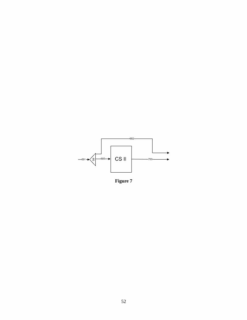
The imposition of the constraint defined in Equation 38 requires the introduction of a bypass
stream, (see Figure 7).
Figure 7
The goal of this stream is to deactivate those constraints associated with the second stage of crys-
tallization whenFs > 0, Du = 0, s ∈ SOu , u ∈ UCSII , i.e. when the flowrate is nonzero but the
transfer area is zero, the constraint from Equation 38 cannot be met. Therefore, using the notation
from Figure 7, this can be represented by a disjunction as follows:
¬yu, ∀u ∈ UCSII
F602 ≥ 0
F602c ≥ 0, c ∈ C
FL602 ≥ 0
ξ602 ≥ 0
F603 = 0
F603c = 0, c ∈ C
FL603 = 0
ξ603 = 0
∨
∨
u∈UCSII
[yu]
F602 = 0
F602c = 0, c ∈ C
FL602 = 0
ξ602 = 0
F603 ≥ 0
F603c ≥ 0, c ∈ C
FL603 ≥ 0
ξ603 ≥ 0
(43)
Introducing the binary variablez, wherez = 1 means that
∃u ∈ UCSII : yu = 1
, this can be
16
represented in logic form as:
∨
u∈UCSII
yu ⇔ z (44)
which is equivalent to:
(
∨
u∈UCSII
yu ⇒ z
)
∧
(
z ⇒∨
u∈UCSII
yu
)
(45)
Transforming these logic propositions into inequalities yields24:
z − yu ≥ 0 ∀u ∈ UCSII (46)
∑
u∈UCSII
yu − z ≥ 0 (47)
Therefore, the above disjunction can be additionally represented by:
F603 ≤ FU603z (48)
F603c ≤ FU603cz (49)
FL603 ≤ FLU603z (50)
ξ603 ≤ ξU603z (51)
F602 ≤ FU602 (1 − z) (52)
F602c ≤ FU602c (1 − z) (53)
FL602 ≤ FLU602 (1 − z) (54)
ξ602 ≤ ξU602 (1 − z) (55)
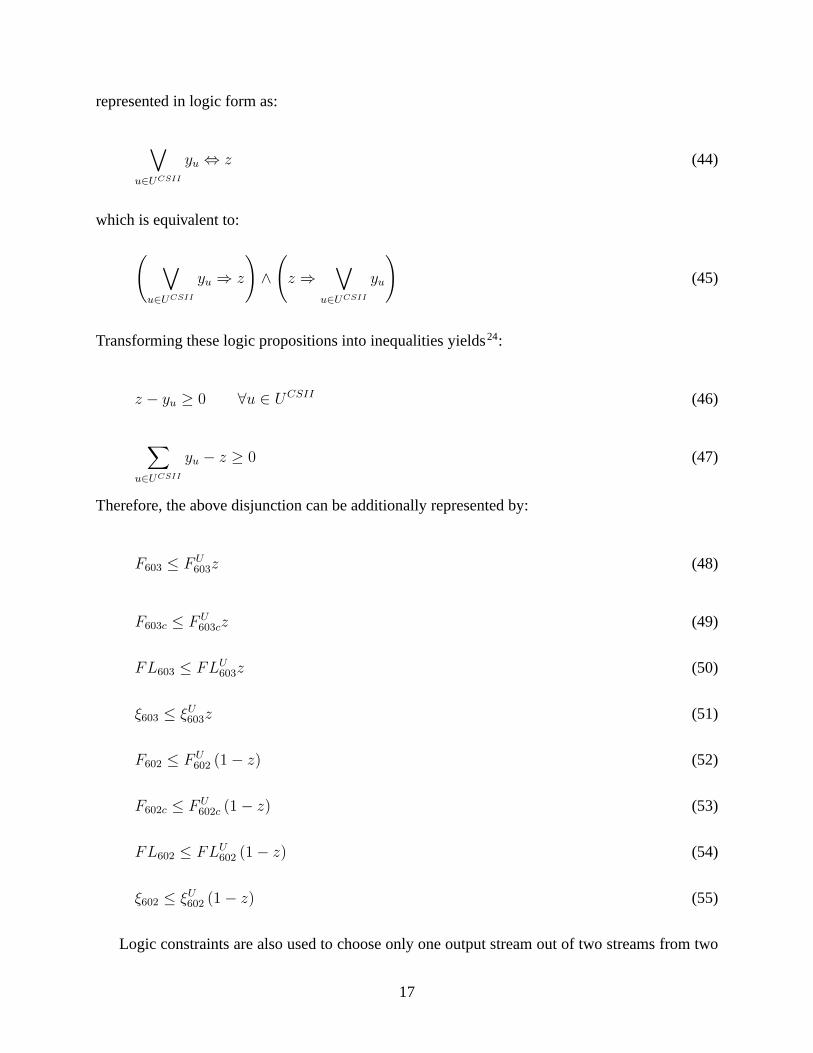
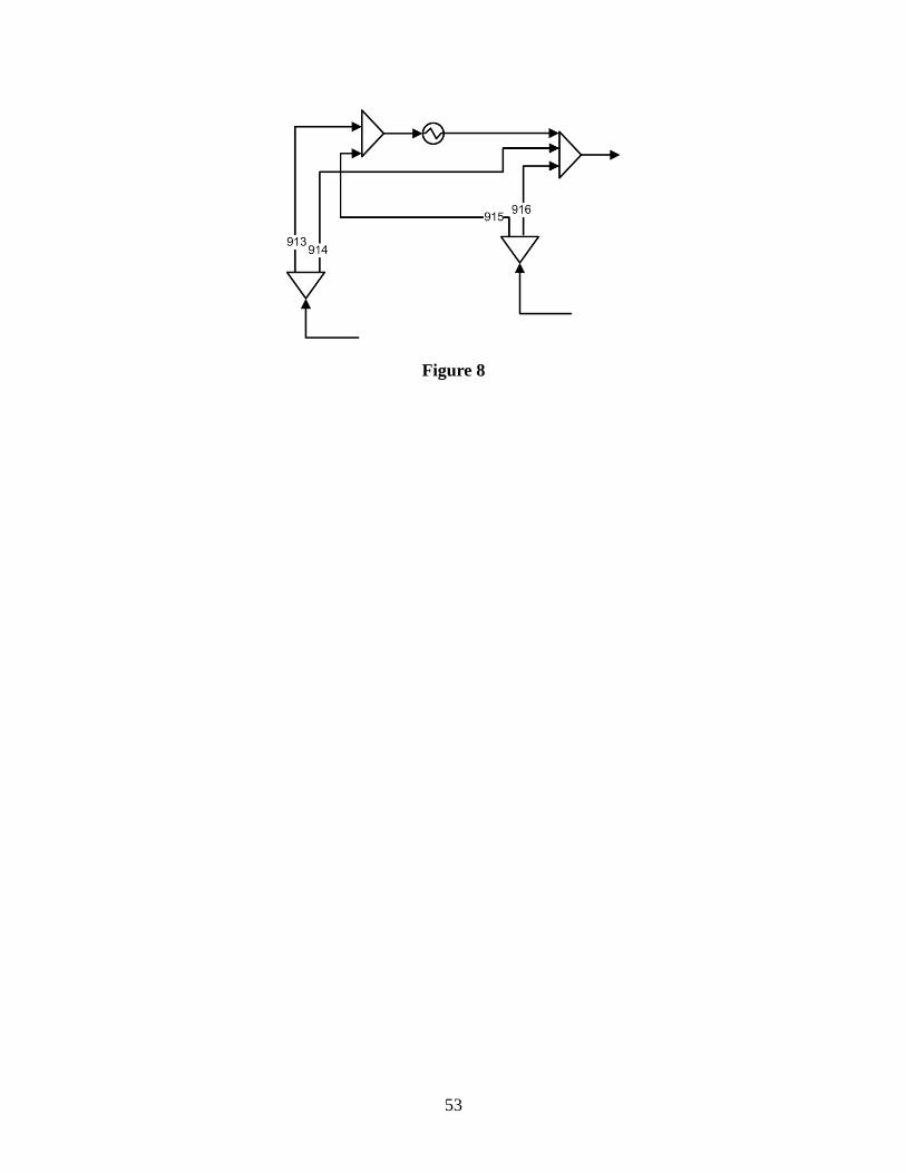
Logic constraints are also used to choose only one output stream out of two streams from two
17
specific splitters. These constraints are introduced to avoid splitting one stream into two streams,
heat one of the streams and afterwards mix them again. Figure8 illustrates an extract of the
superstructure with the two splitters where the constraints were imposed.
Figure 8
Following the notation used in Figure 8, these constraints can be logically represented as:
z1
F913 ≥ 0
F913c ≥ 0
FL913 ≥ 0
ξ913 ≥ 0
F914 = 0
F914c = 0
FL914 = 0
ξ914 = 0
∨
¬z1
F913 = 0
F913c = 0
FL913 = 0
ξ913 = 0
F914 ≥ 0
F914c ≥ 0
FL914 ≥ 0
ξ914 ≥ 0
(56)
z2
F915 ≥ 0
F915c ≥ 0
FL915 ≥ 0
ξ915 ≥ 0
F916 = 0
F916c = 0
FL916 = 0
ξ916 = 0
∨
¬z2
F915 = 0
F915c = 0
FL915 = 0
ξ915 = 0
F916 ≥ 0
F916c ≥ 0
FL916 ≥ 0
ξ916 ≥ 0
(57)
18
and converted into inequality constraints using a big-M transformation:
F913 ≤ FU913z1 (58)
F913c ≤ FU913cz1 (59)
FL913 ≤ FLU913z1 (60)
ξ913 ≤ ξU913z1 (61)
F914 ≤ FU914 (1 − z1) (62)
F914c ≤ FU914c (1 − z1) (63)
FL914 ≤ FLU914 (1 − z1) (64)
ξ914 ≤ ξU914 (1 − z1) (65)
F915 ≤ FU915z2 (66)
F915c ≤ FU915cz2 (67)
FL915 ≤ FLU915z2 (68)
ξ915 ≤ ξU915z2 (69)
F916 ≤ FU916 (1 − z2) (70)
F916c ≤ FU916c (1 − z2) (71)
FL916 ≤ FLU916 (1 − z2) (72)
ξ916 ≤ ξU916 (1 − z2) (73)
wherez1 = 1 if F913 ≥ 0, andz2 = 1 if F915 ≥ 0.
19
Solution approach
The MINLP model described was implemented using the modeling system GAMS.25 The model
has 3054 constraints, 2991 continuous variables and 101 binary variables. The latter are associated
with the existence of equipment units, and with the solubility equations and logic constraints. The
nonlinearities arise from the mass balances for the splitters, heat balances, density correlations,
solubility correlations and from the mass balances for centrifuges, resulting in a nonconvex MINLP
problem.
The first case that we have studied was the synthesis of p-xylene recovery from a stream with
65 wt % of p-xylene. As a first approach DICOPT26 was employed to solve the MINLP problem.
However, there were difficulties for obtaining feasible solutions for the relaxed MINLP problem,
resulting on several failures to get optimum solutions. Specifying a good starting point and up-
per bounds based on process insights allowed DICOPT to obtain optimum solutions for the re-
laxed MINLP problem and nonlinear programming (NLP) subproblems. However, because of the
nonconvexities of the model this solver was highly dependent on the starting point of the inte-
ger variables, and several suboptimal solutions were obtained. As a second approach, the solver
GAMS/SBB was employed with a maximum number of nodes set to 500, and then its output solu-
tion was used as an initial point for GAMS/DICOPT, but a clearimprovement was not observed.
In order to obtain better solutions to the MINLP model in shorter time and in a more robust
way, a two-level decomposition approach is proposed. This approach consists of the solution of
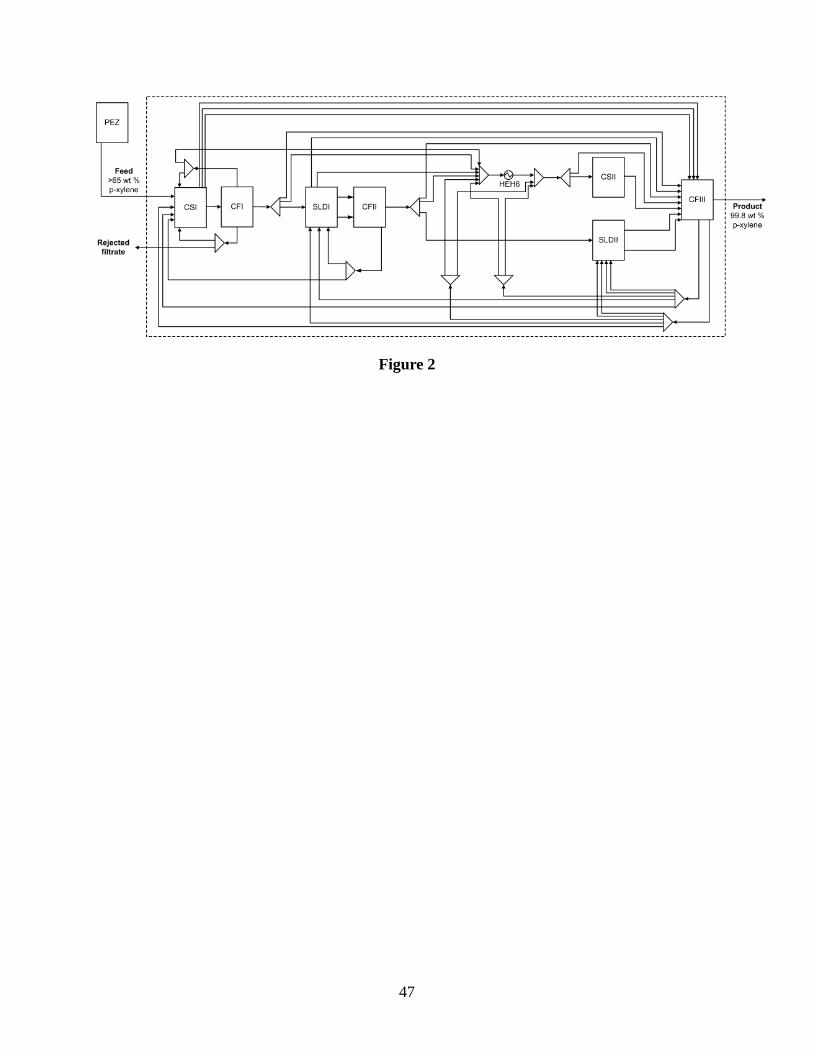
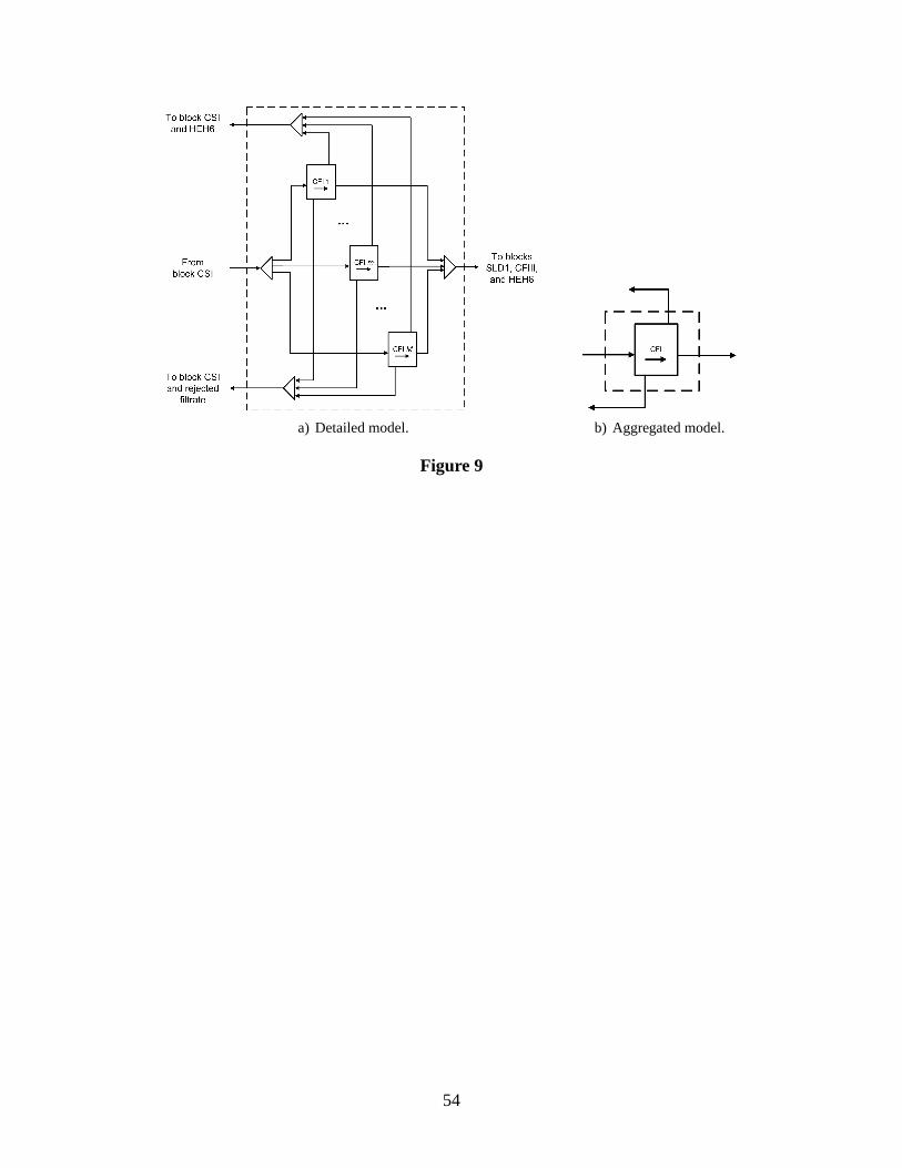
an aggregated model and a detailed model. In the proposed superstructure (see Figure 2) the block
CFI corresponds to a set of centrifuges in parallel as illustrated in Figure 9a).
Figure 9
This block and the additional blocks CFII and CFIII, suggested an aggregated model, where the
set of units in parallel would be substituted by only one unit(see Figure 9b)).
The two key ideas in the aggregated model are: (1) merging theunits in centrifuge blocks and
slurry drums into single input-output blocks so that the aggregated model is defined in the space of
20
interconnection of major blocks, and (2) the relaxation of the constraints that set an upper bound
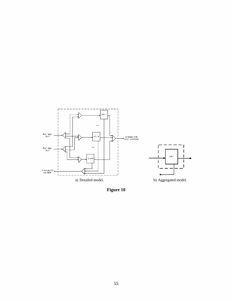
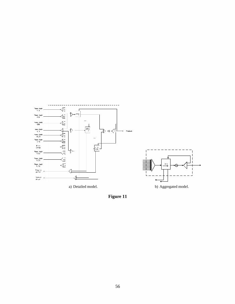
on the inlet flowrate of each centrifuge unit in order to meet the same production targets. Figures 9,
10 and 11 show the set of centrifuges in parallel in the detailed model and the respective structure
defined in the aggregated model.
Figure 10
Figure 11
From these figures one can see the degree of simplicity achieved by aggregating each of the sets of
centrifuges in parallel into only one centrifuge. This means that in the mathematical model a large
number of equations and variables are replaced by equationsof a single equivalent unit.
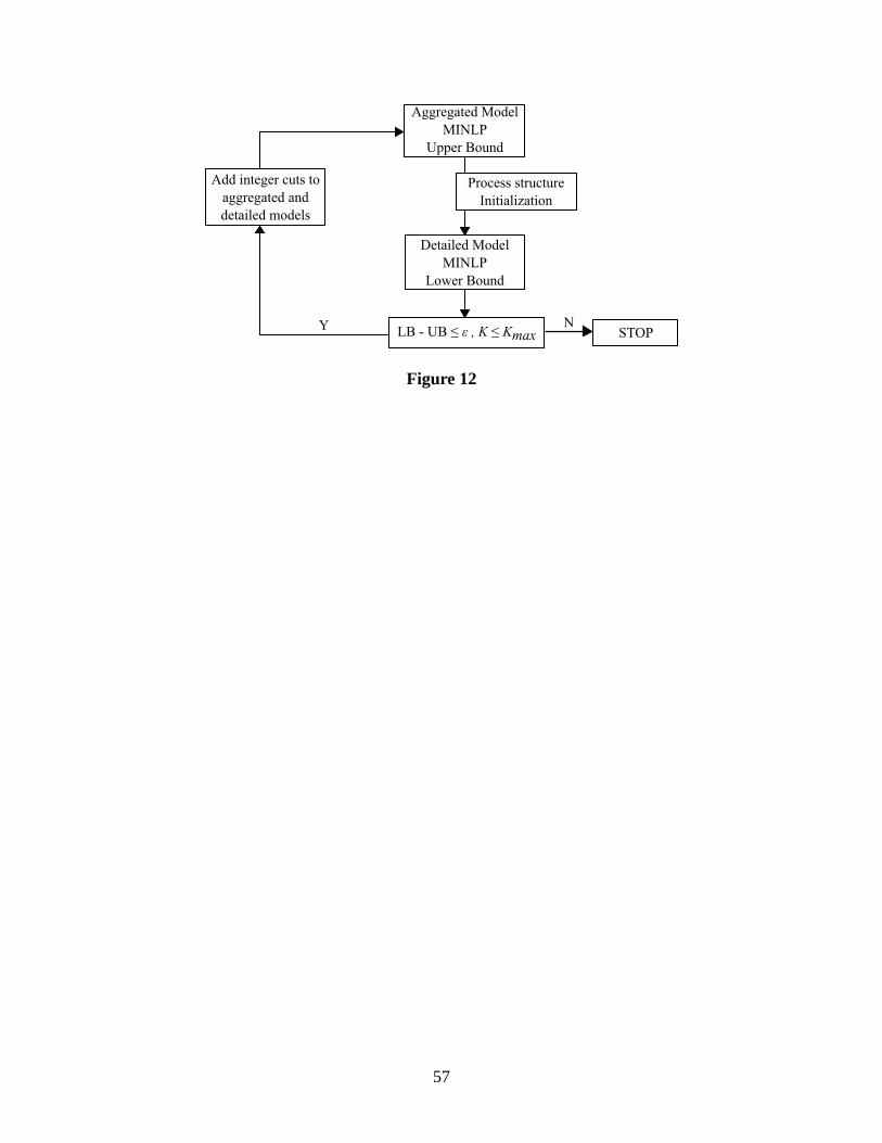
The two-level decomposition approach is applied accordingly with the algorithm illustrated in
Figure 12.
Figure 12
Note that the aggregated and detailed models are formulatedas MINLP models. The optimum
solution of the aggregated model is used to initialize and define the superstructure of the detailed
model. In particular, streams with zero flowrate in the solution of the aggregated model are re-
moved from the superstructure of the detailed model. The aggregated model yields an upper bound
on the total annual cost (see next section) while the detailed model yields a lower bound. The al-
gorithm iterates between the solution of the aggregated anddetailed model until the difference
between the bounds is less than a specified tolerance. Between each iteration two integer cuts are
added to expedite the search. The next three subsections give the details about the bounds of each
problem, the integer cuts added between the two levels, and the definition and initialization of the
detailed model.
Bounds on the cost
Generally for a minimization problem, it would be expected that the aggregated model yields a
lower bound on the objective function due to relaxations on some constraints or the underestimation
21
of the objective function. However, in this work the aggregated model yields an upper bound. This
bound is the result of a more constrained model because the aggregated model only uses one unit
in the blocks CFI, CFII, and CFIII instead of a combination ofunits in parallel.
In the aggregated model each block of centrifuges CFI, CFII,and CFIII is represented by only
one centrifuge with the maximum inlet flowrate constraints relaxed. Note that the relaxations
imposed in the maximum inlet flowrate of the centrifuges do not contribute to obtain a lower
bound. However, this aggregation has two important implications: (1) in the detailed model in
each block of centrifuges the units can operate at differenttemperatures, while in the aggregated
model the aggregated centrifuge can only operate at a singletemperature, (2) the performance of
the aggregated unit can be different of the set of units combined in parallel. In the first point it is
easy to understand that the lack of flexibility to operate thecentrifuges at different temperatures
may lead to a more constrained model and consequently to an upper bound. However, the second
point needs to be explained in more detail. Here, the term performance is used to relate the output
of a centrifuge with the same inlet flowrate.
Generally, the performance of a set of units in parallel is only equivalent to a single unit with an
equivalent capacity if all the equations describing the units are linear. However, when the units are
described by nonlinear equations, the performance of a set of units in parallel and one equivalent
unit may not be the same. In Appendix A it is shown that the feasible region of the aggregated
model is a subregion of the detailed model, and therefore thefirst yields an upper bound on the
objective function.
Integer cuts
At each iteration of the two-level decomposition, one specific integer cut is added in each level in
order to expedite the search. In the aggregated level an integer cut is implemented, with the goal
of eliminating from the solution combinations of aggregated blocks with a previous equivalent
number of centrifuges, where equivalent number of centrifuges denotes the number of centrifuges
obtained from the ceiling of the ratio between the inlet flowrate and the maximum inlet flowrate of
22
each centrifuge,
NCFI =
⌈
FsSX
FUsSX
⌉
∀u ∈ UCFI , ∀s ∈ SIu (74)
NCFII =
⌈
Fs
FUs
⌉
∀u ∈ UCFII , ∀s ∈ SIu (75)
NCFIII =
⌈
FsSX
FUsSX
⌉
∀u ∈ UCFIII , ∀s ∈ SIu (76)
whereNCFI ,NCFII andNCFIII are the equivalent number of required centrifuges to deal with the
inlet streams,FsSX is the flowrate of solid p-xylene,FUsSX is the upper bound on the inlet flowrate
of solid p-xylene,Fs is the total inlet flowrate andFUs the upper bound of the total inlet flowrate.
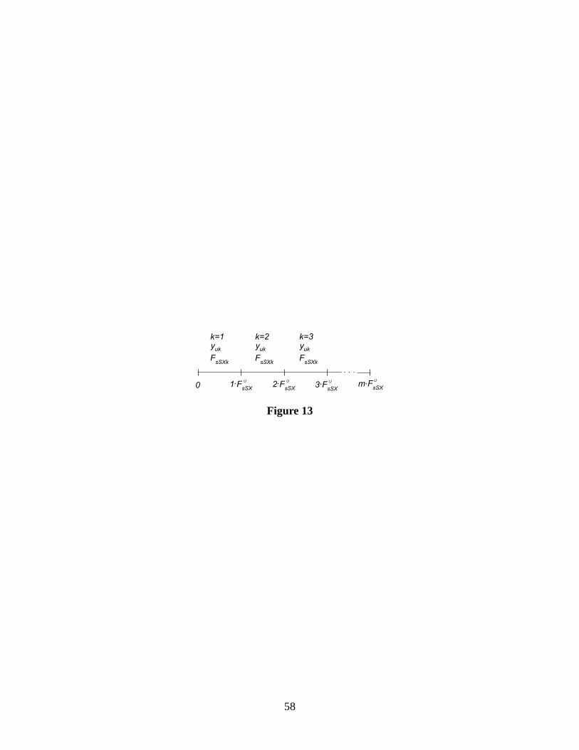
Instead of using Equations 74 to 76, additional binary variables,yuk, and disaggregated vari-
ables,FsSXk orFsk, are introduced for each block to represent the actual number of unitsk. Figure
13 depicts the partition, in terms of these variables, forFsSX , where the disaggregated variable
FsSXk has as lower boundFUsSX (kyuk − 1) + ε, and upper boundkyukF
UsSX .
Figure 13
This is represented mathematically by:
FsSX =M∑
k=1
FsSXk ∀u ∈ UCFI , ∀s ∈ SIu (77)
FsSXk ≤ FUsSXkyuk k = 1, ...,M ;∀u ∈ UCFI , ∀s ∈ SI
u (78)
FsSXk ≥ FUsSX (kyuk − 1) + ε k = 1, ...,M ;∀u ∈ UCFI , ∀s ∈ SI
u (79)
M∑
k=1
yuk = 1 ∀u ∈ UCFI (80)
Fs =N∑
k=1
Fsk ∀u ∈ UCFII , ∀s ∈ SIu (81)
Fsk ≤ FUs kyuk k = 0, ..., N ;∀u ∈ UCFII , ∀s ∈ SI
u (82)
23
Fsk ≥ FUs (kyuk − 1) + ε k = 1, ..., N ;∀u ∈ UCFII , ∀s ∈ SI
u (83)
N∑
k=0
yuk = 1 ∀u ∈ UCFII (84)
FsSX =P∑
k=1
FsSXk ∀u ∈ UCFIII , ∀s ∈ SIu (85)
FsSXk ≤ FUsSXkyuk k = 1, ..., P ;∀u ∈ UCFIII , ∀s ∈ SI
u (86)
FsSXk ≥ FUsSX (kyuk − 1) + ε k = 1, ..., P ;∀u ∈ UCFIII , ∀s ∈ SI
u (87)
P∑
k=1
yuk = 1 ∀u ∈ UCFIII (88)
whereM , N andP are the maximum number of units in each aggregated block CFI,CFII and
CFIII, respectively,FsSXk andFsk are disaggregated variables,yuk are binary variables andε is a
small number. Thus, for all blocks the integer cut is defined by the following expression:
∑
u|yKu ∈P K
yKu +
∑
e|yKe ∈P K
yKe −
∑
u|yKu ∈NK
yKu −
∑
e|yKe ∈NK
yKe 6
∣
∣PK∣
∣− 1 (89)
where
PK =(
u|yKu = 1
∪
e|yKe = 1
)
,NK =(
u|yKu = 0
∪
e|yKe = 0
)
with
u|u ∈ UCRT ∪ USLD
ande = (lk) with
lk :(
l ∈ UCFI , k = 1, ..., j)
∪(
l ∈ UCFII , k = 1, ...,m)
∪(
l ∈ UCFIII , k = 1, ..., n)
andK denotes the iteration number of the two-level decomposition. Therefore, despite the fact
that for each aggregated unit of centrifuges there is only one unit, an integer cut can be used to
eliminate solutions with previous equivalent number of centrifuges.
The second cut was applied at the detailed level to avoid the repetition of previous combinations
of units in the solution. In this case the integer cut is defined by Equation 90, associated with
24
Equations 91, 92 and 93.
∑
i|yKu ∈P K
yKu −
∑
i|yKu ∈NK
yKu 6
∣
∣PK∣
∣− 1 (90)
wherePK =
u|yKu = 1
, NK =
u|yKu = 0
,
u : u ∈(
UCFI ∪ UCFII ∪ UCFIII)
andK
denotes the iteration number of the two-level decomposition. In addition, to avoid symmetric
solutions inside of each block of centrifuges the followingequations were considered:
yk ≥ yk+1; k = 1, ...,M − 1 (91)
yk ≥ yk+1; k = 1, ..., N − 1 (92)
yk ≥ yk+1; k = 1, ..., P − 1 (93)
which set an order of selection for the units in parallel.
In the aggregated model the logic relationships between thebinary variables assigned to each
block,yu and the disaggregated binary variables is as follows:
∨
k=1,...,M
yuk ⇔ yu ∀u ∈ UCFI (94)
∨
k=1,...,N
yuk ⇔ yu ∀u ∈ UCFII (95)
∨
k=1,...,P
yuk ⇔ yu ∀u ∈ UCFIII (96)
Transforming these logic propositions into inequalities yields24:
yu − yuk ≥ 0 ∀u ∈ UCFI , k = 1, ...,M (97)
M∑
k=1
yuk − yu ≥ 0 ∀u ∈ UCFI (98)
25
yu − yuk ≥ 0 ∀u ∈ UCFII , k = 1, ..., N (99)
N∑
k=1
yuk − yu ≥ 0 ∀u ∈ UCFII (100)
yu − yuk ≥ 0 ∀u ∈ UCFII , k = 1, ..., P (101)
P∑
k=1
yuk − yu ≥ 0 ∀u ∈ UCFII (102)
Initialization of the detailed model
In the proposed decomposition approach, the aggregated model describes the superstructure de-
fined in Figure 2. The optimization of the aggregated model provides solutions with several zero
flowrates. This information is used to define a new superstructure for the detailed model, where
the streams with zero flowrate in the aggregated model are removed from the superstructure of
the detailed model. Therefore, an analysis of the input and output streams of splitters and mix-
ers is made in order to remove from the detailed model the splitters with only one output stream
and mixers with only one input stream. In this way several additional equations and variables are
removed from the detailed model, decreasing considerably the size of the problem. In addition,
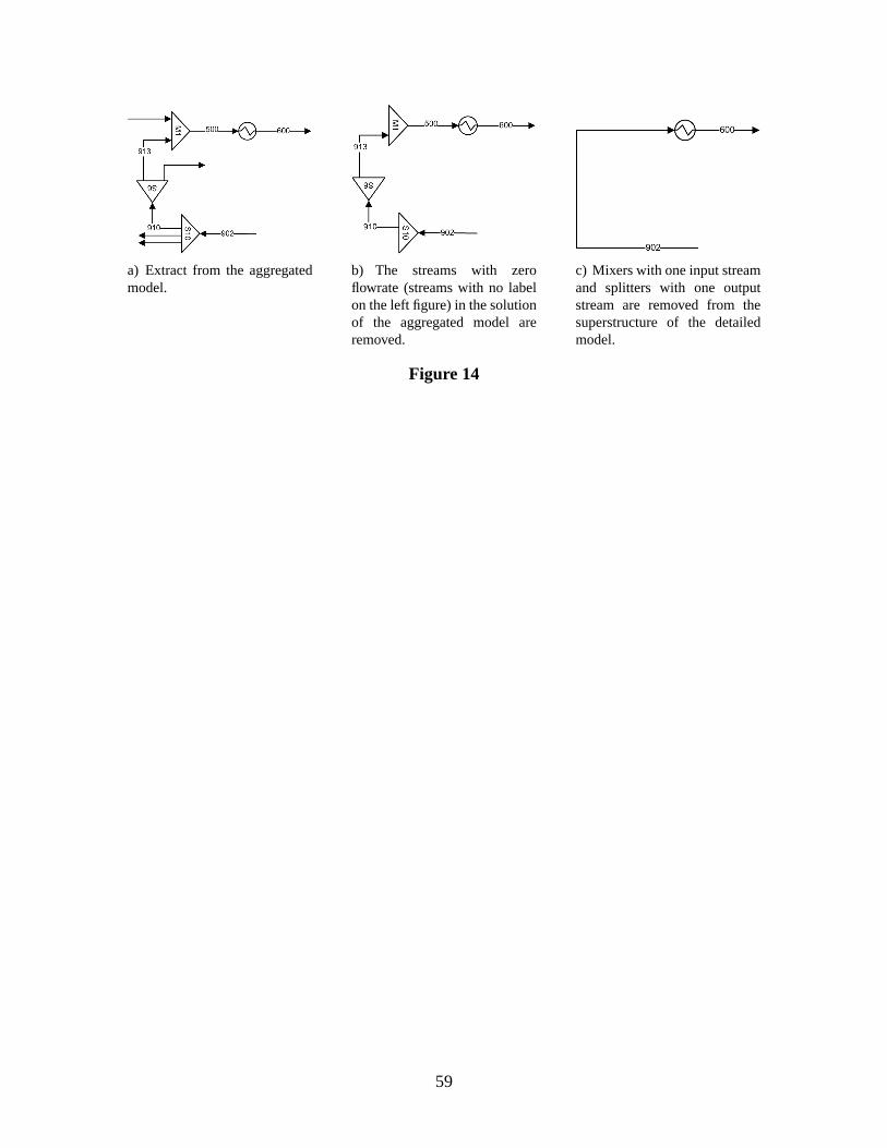
singularities that may appear due to many zero entries in theJacobian matrix are avoided.27 Figure
14 illustrates the reduction in terms of units and streams that can occur with this model reduction.
In the detailed model the variables associated with the streams represented in Figure 2 are initial-
ized using the values of the final solution of the aggregated model. However, it was necessary to
devise an initialization strategy for the continuous and binary variables associated with the streams
and units inside the blocks CFI, CFII, and CFIII.
Figure 14
As a first approach, based on the solution of the aggregated model, the number of units of
blocks CFI, CFII, and CFIII (calculated by Equations 74 to 76) were set as the maximum number
of units in the detailed model. However, due to nonlinearities this restriction has shown to elim-
inate some combinations of units from better solutions. Therefore, three alternative approaches
26
were considered, where the main idea is to avoid starting points with sets of variables with zero
values that could cause problems to the solvers. The first alternative approach consists of using the
maximum number of units in each block, initialize each binary variable associated with each unit
and divide the feed stream equally to each unit. The second alternative approach consists in using
the values of units calculated by Equations 74 to 76, and divide 99 % of the feed stream to those
units, with only those initiated withyu = 1, while the remaining units share 1% of the feed stream
andyu = 0. The third alternative divides the flowrate as in the second but all the binary variables
were initialized withyu = 1.
Decomposition strategy
The steps of the suggested decomposition are as follows:
Step 1. SetK = 1 andKmax. SetZU = ∞ andZL = −∞.
Step 2. Aggregate centrifuges in blocks, redefine new input and output streams of the aggregated
blocks. Select an initial starting point and flowsheet throughyuk andyu.
Step 3. Solve the aggregated MINLP model to yieldZKU . If ZK
U ≤ ZU thenZU = ZKU .
Step 4. Add the integer cut from Equation 89.
Step 5. Remove streams, splitters, mixers, drums, heat exchangersand crystallizers not used in the
solution of the aggregated model. Define new input streams into units due to the elimination
of streams and some units. Disaggregate the units in each centrifuge block using either of
the three alternative approaches. Set the starting point with the solution from the aggregated
model.
Step 6. Solve the detailed MINLP to yieldZKL . IF ZK
L ≥ ZL thenZL = ZKL .
Step 7. Add the integer cut from Equation 90.
27
Step 8. If
∃u|yu = 1, Fs = 0,
u : u ∈(
UCFI ∪ UCFII ∪ UCFIII)
, s|s ∈ SIu
add an integer
cut (Equation 90), updateyu andZKL , and add one more integer cut (Equation 90) to the
detailed model.
Step 9. If ZL ≥ ZU orK > Kmax thenZ∗ = ZL, STOP. Otherwise go to 3.
Remarks
1. In the aggregated model the variables and the equations associated with the streams not
present are not considered; i.e. they are eliminated from the model, instead of setting some
binary variables to zero.
2. In the detailed model the only variables that cannot be initialized using the values from the
aggregated model correspond to the variables associated with some streams of slurry drum
blocks. All other variables can be initialized from the aggregated model solution.
3. Both MINLP models, aggregated and detailed, are nonconvex and have multiple suboptimal
solutions. At each iteration of the two-level decomposition the MINLP problem is not solved
to global optimality, which may lead to situations where thesolution of the detailed model
could be worse than the solution of the aggregated model.
4. Both integer cuts, Equations 89 and 90 are added to avoid the repetition of previous config-
urations. These integer cuts complement the cuts applied within DICOPT26, since the last
are applied to all integer variables of the problem, while cuts imposed by the decomposition
are only applied to the integer variables related with the process units. The integer cut added
to the detailed model, is expected to increase the lower bound of the objective function, thus
a stopping criterion was developed based on the crossing of upper and lower bound. In ad-
dition, a criterion based on the maximum number of iterations of the decomposition was
implemented.
5. Deterministic algorithms for global optimization, suchas BARON28 and LINDOGlobal29
were not able to be solved in many hours.
28
Numerical results
The proposed superstructure and decomposition strategy were applied to three cases with different
p-xylene compositions in the feed stream: Case I with 65 wt %,Case II with 90 wt % and Case
III with 98 wt %. For all cases the product specification is a stream with a flowrate of 13.8 kg/s
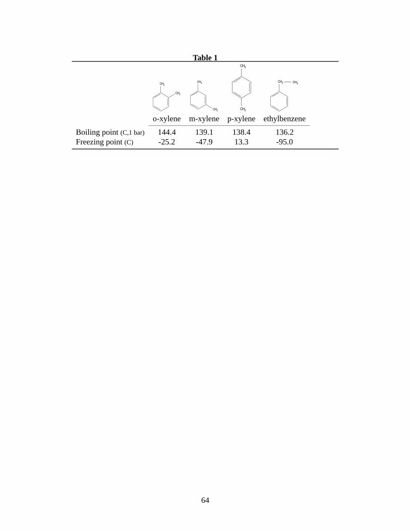
and 99.8 wt % of p-xylene. These compositions were taken fromHubbell and Rutten3 , who have
proposed different flowsheets for each one. With these caseswe pretend to cover the more recent
trend where the crystallization is used as a second stage in the p-xylene recovery. Therefore, the
inlet feed stream can be the output of an adsorption process.3
Note that the same prices for the feed and rejected filtrate are considered in the three afore-
mentioned cases. This means that a feed with 65 wt % and another with 98 wt % p-xylene have
the same economic value. Although this may not be accurate, the feed costs and rejected filtrate
costs only influence the value of the objective function and do not have any influence in the struc-
ture of the optimum flowsheet. This was supported by several optimizations using different cost
parameters.
The MINLP models and the decomposition strategy were implemented using GAMS25 and
solved on a computer running Linux with a Intel Xeon CPU, 1.86GHz and 8GB of RAM. The
strategy used to solve each MINLP problem involved two steps. First, GAMS/SBB was used to
solve the MINLP problem with a maximum number of nodes, and then the output solution from
GAMS/SBB was used as an initial point for GAMS/DICOPT. The aim of this strategy was to
perform a fast screening in the branch and bound tree, and then to try to improve the solution with
GAMS/DICOPT. In this way most of the times GAMS/DICOPT started with a feasible integer
solution.
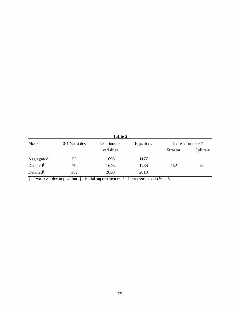
Table 2 shows the sizes of the aggregated model and typical sizes of the detailed models for
Case III. Note that while the size of the aggregated model is fixed for the three cases, the size of
the detailed model can vary depending on the solution of the aggregated model.
Table 2
29
As can be seen, the proposed decomposition scheme requires asignificantly smaller sized MINLP.
Case I
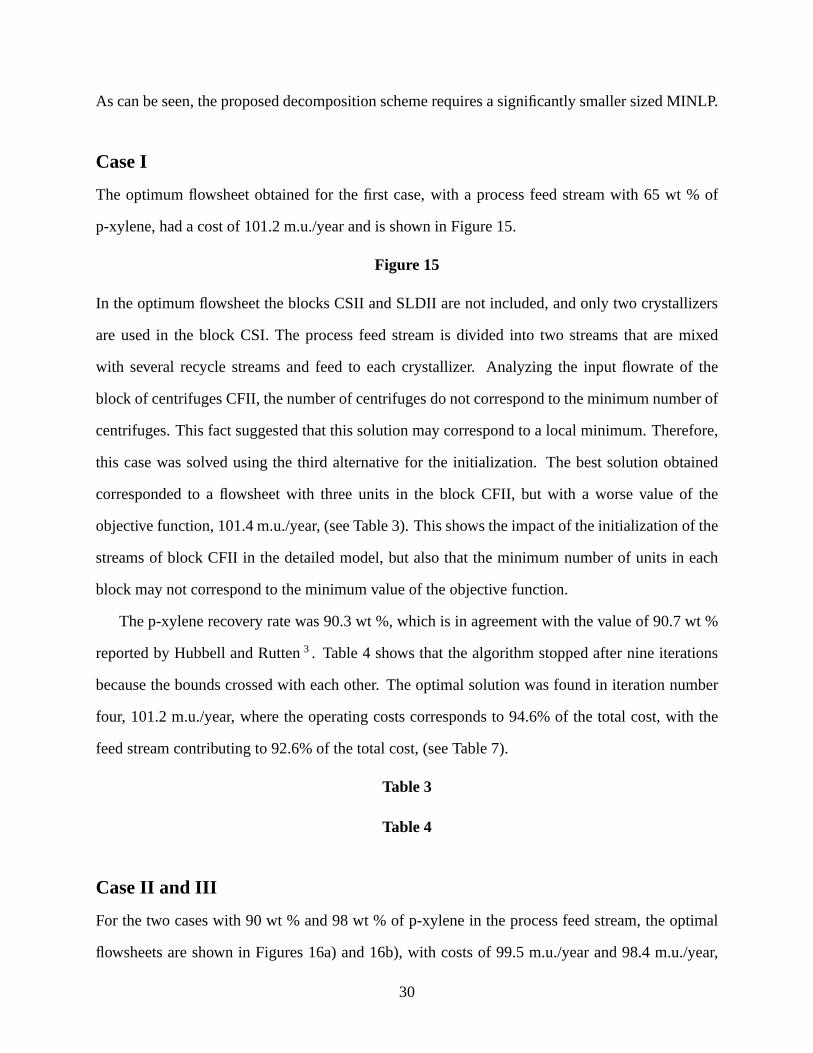
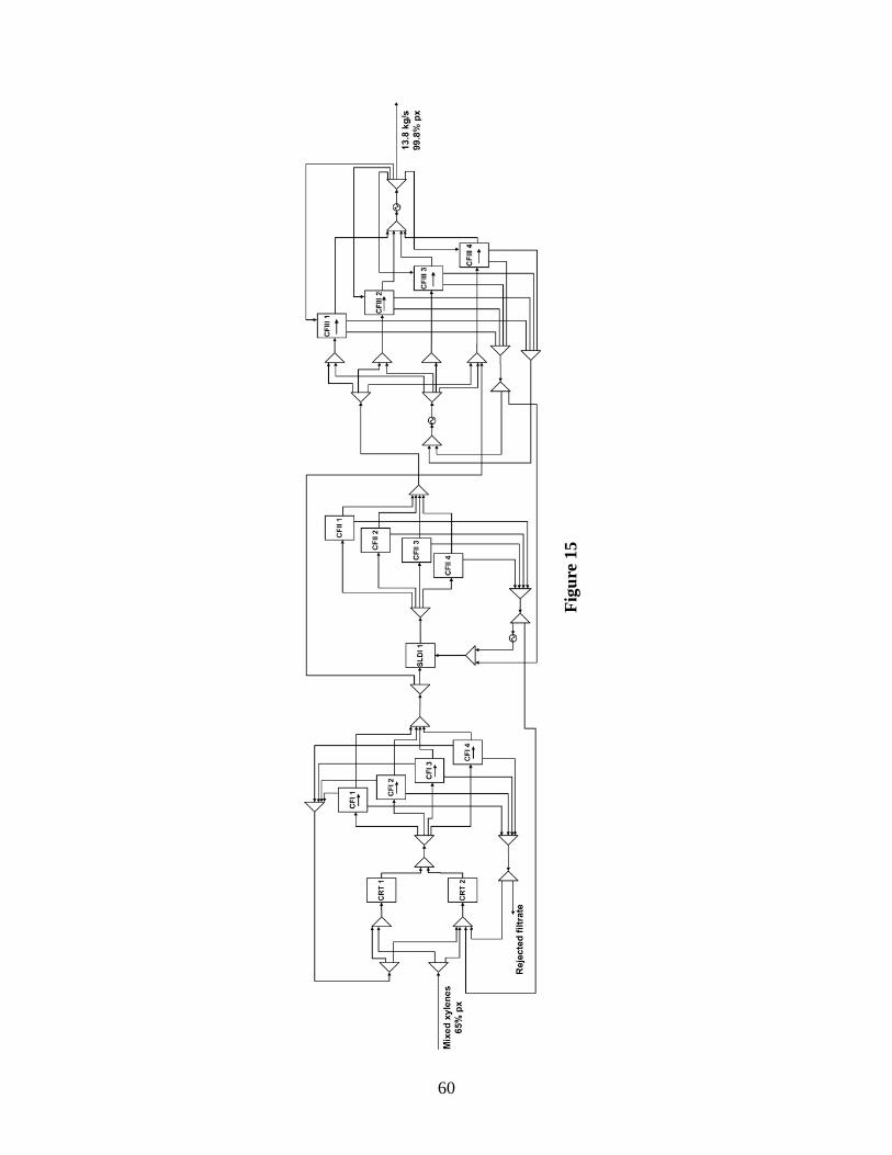
The optimum flowsheet obtained for the first case, with a process feed stream with 65 wt % of
p-xylene, had a cost of 101.2 m.u./year and is shown in Figure15.
Figure 15
In the optimum flowsheet the blocks CSII and SLDII are not included, and only two crystallizers
are used in the block CSI. The process feed stream is divided into two streams that are mixed
with several recycle streams and feed to each crystallizer.Analyzing the input flowrate of the
block of centrifuges CFII, the number of centrifuges do not correspond to the minimum number of
centrifuges. This fact suggested that this solution may correspond to a local minimum. Therefore,
this case was solved using the third alternative for the initialization. The best solution obtained
corresponded to a flowsheet with three units in the block CFII, but with a worse value of the
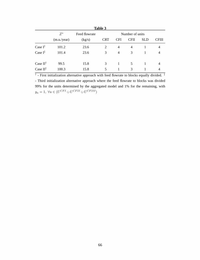
objective function, 101.4 m.u./year, (see Table 3). This shows the impact of the initialization of the
streams of block CFII in the detailed model, but also that theminimum number of units in each
block may not correspond to the minimum value of the objective function.
The p-xylene recovery rate was 90.3 wt %, which is in agreement with the value of 90.7 wt %
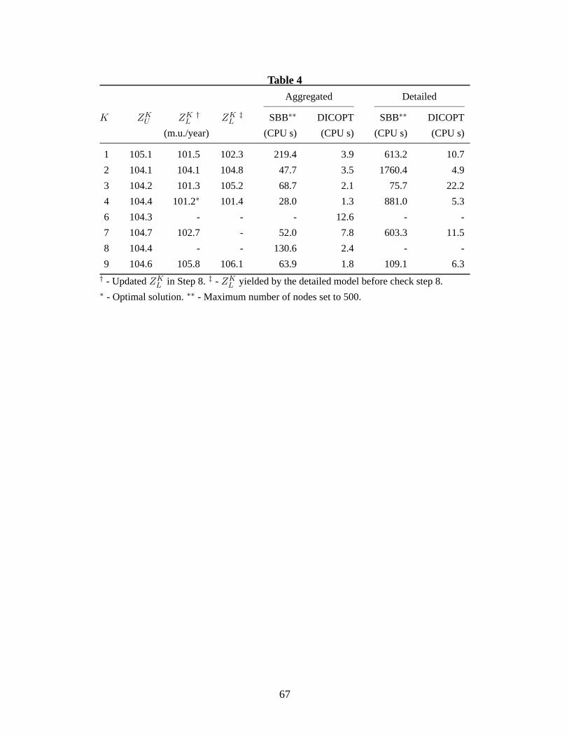
reported by Hubbell and Rutten3 . Table 4 shows that the algorithm stopped after nine iterations
because the bounds crossed with each other. The optimal solution was found in iteration number
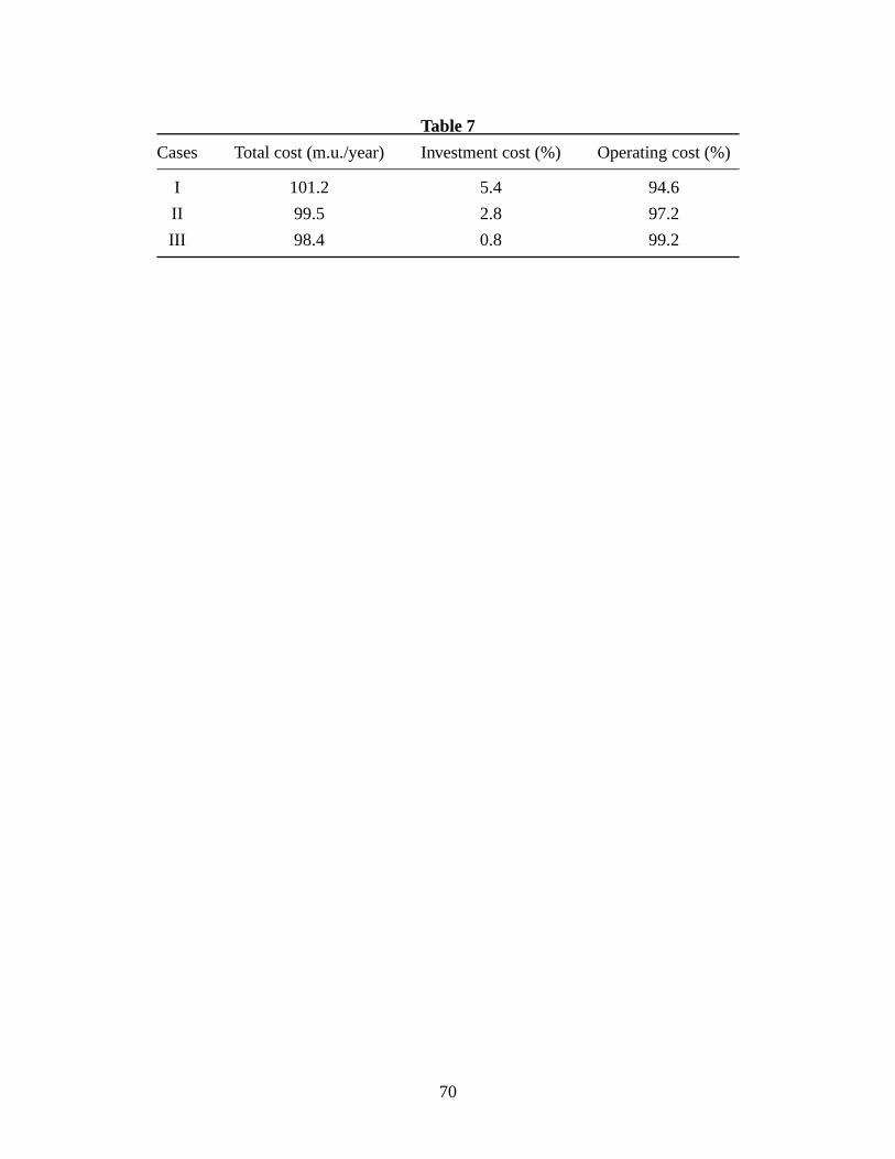
four, 101.2 m.u./year, where the operating costs corresponds to 94.6% of the total cost, with the
feed stream contributing to 92.6% of the total cost, (see Table 7).
Table 3
Table 4
Case II and III
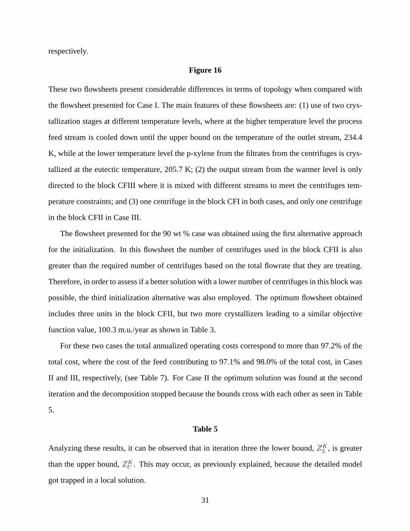
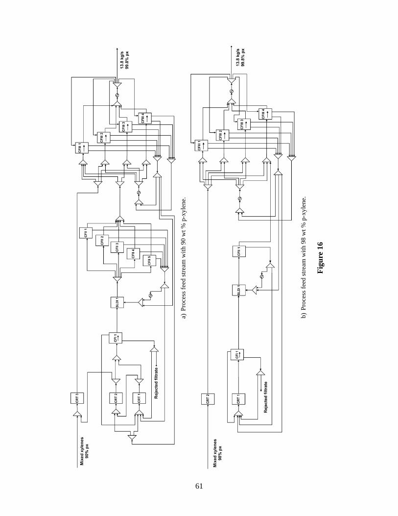
For the two cases with 90 wt % and 98 wt % of p-xylene in the process feed stream, the optimal
flowsheets are shown in Figures 16a) and 16b), with costs of 99.5 m.u./year and 98.4 m.u./year,
30
respectively.
Figure 16
These two flowsheets present considerable differences in terms of topology when compared with
the flowsheet presented for Case I. The main features of theseflowsheets are: (1) use of two crys-
tallization stages at different temperature levels, whereat the higher temperature level the process
feed stream is cooled down until the upper bound on the temperature of the outlet stream, 234.4
K, while at the lower temperature level the p-xylene from thefiltrates from the centrifuges is crys-
tallized at the eutectic temperature, 205.7 K; (2) the output stream from the warmer level is only
directed to the block CFIII where it is mixed with different streams to meet the centrifuges tem-
perature constraints; and (3) one centrifuge in the block CFI in both cases, and only one centrifuge
in the block CFII in Case III.
The flowsheet presented for the 90 wt % case was obtained usingthe first alternative approach
for the initialization. In this flowsheet the number of centrifuges used in the block CFII is also
greater than the required number of centrifuges based on thetotal flowrate that they are treating.
Therefore, in order to assess if a better solution with a lower number of centrifuges in this block was
possible, the third initialization alternative was also employed. The optimum flowsheet obtained
includes three units in the block CFII, but two more crystallizers leading to a similar objective
function value, 100.3 m.u./year as shown in Table 3.
For these two cases the total annualized operating costs correspond to more than 97.2% of the
total cost, where the cost of the feed contributing to 97.1% and 98.0% of the total cost, in Cases
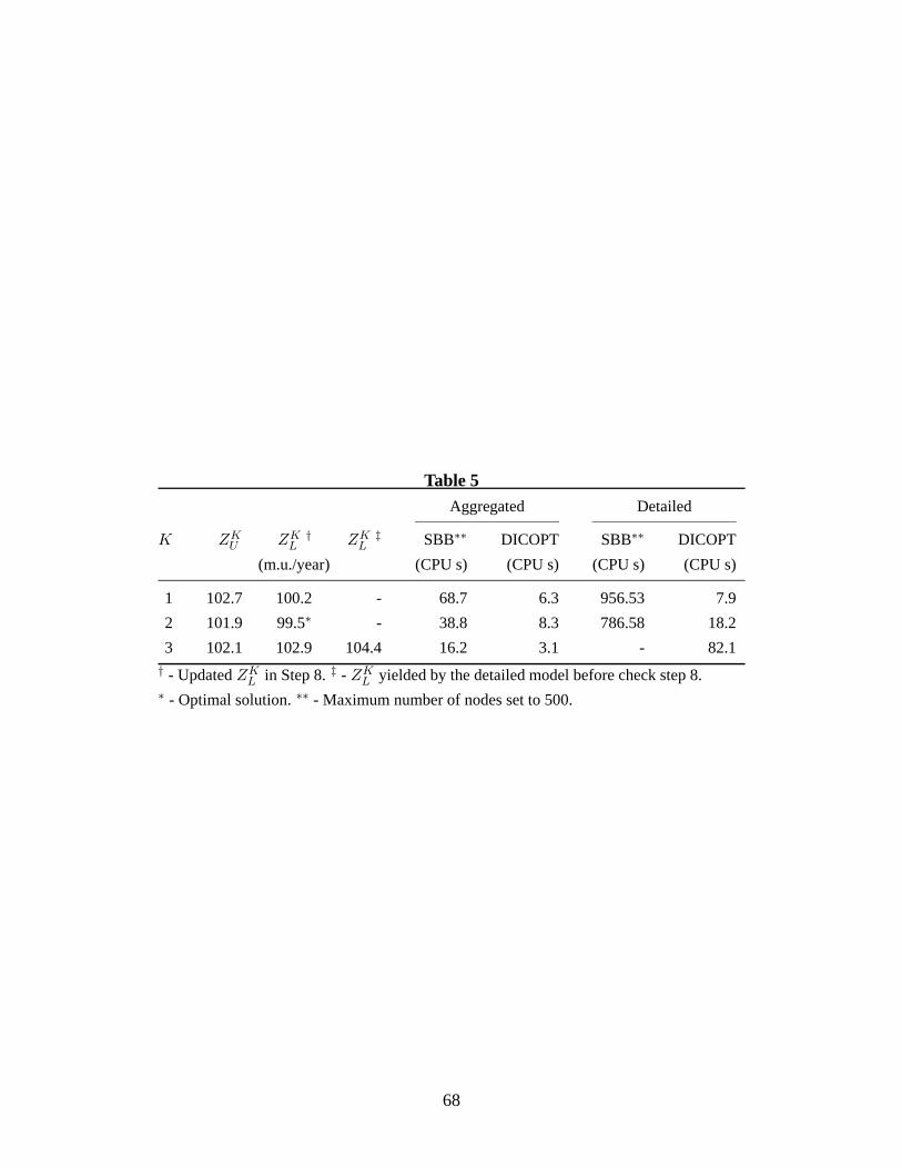
II and III, respectively, (see Table 7). For Case II the optimum solution was found at the second
iteration and the decomposition stopped because the boundscross with each other as seen in Table
5.
Table 5
Analyzing these results, it can be observed that in iteration three the lower bound,ZKL , is greater
than the upper bound,ZKU . This may occur, as previously explained, because the detailed model
got trapped in a local solution.
31
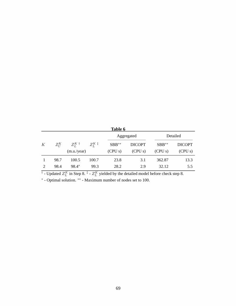
Table 6 shows the results for each iteration of Case III, where it can observed that the decompo-
sition stopped after two iterations because the bounds crossed with each other. In this case, in the
second iteration the value of the lower bound, 98.4 m.u./year, is similar to the value of the upper
bound. This can occur because in the solution of both models the blocks CFI and CFII only have
one unit, and therefore the effect of units in parallel is notpresent here as discussed in Appendix
A. Note also, that the algorithm did not stop in the first iteration, even withZKL > ZK
U , because the
stop criteria is relaxed for the first iteration.
Table 6
The p-xylene recovery rates obtained for these processes were 97.4 wt % and 99.5 wt % for
the feed streams with 90 wt % and 98 wt %, respectively. The optimum flowsheets obtained in this
work are similar to the ones proposed by Hubbell and Rutten3 and Wilsak11 . For the feed streams
with high concentrations of p-xylene they also suggest flowsheets where the feed stream is cooled
down at a warmer level in a set of crystallizers and the outputslurry is centrifuged, separating the
filtrate from the desired high concentration p-xylene product. Their flowsheets include also another
set of crystallizers to recover the p-xylene from the previously mentioned filtrate, and additional
filtrates from centrifuges used to separate the output slurry from a second stage of crystallizers.
However, due to the lack of information in these patents in terms of operating conditions and
number of units, it is not possible to perform a detailed comparison.
In our superstructure all units have bounds on the inlet and outlet temperatures. These bounds
not only constrain the feasible links between the units, butalso the mixing of streams to meet
constraints in the inlet streams of centrifuges. Therefore, different specifications for the inlet or
outlet temperature streams can change the operating conditions and give rise to different flowsheets
with alternative topologies.
Table 7
32
Conclusions
In this paper we have proposed a mathematical programming approach for the optimal synthesis
of p-xylene recovery based on crystallization. Our approach consists of the following three major
steps: a) development of a superstructure for the crystallization and associated liquid/solid separa-
tion stages; b) formulation of an MINLP model associated with the superstructure; and c) solution
of the MINLP model employing a decomposition approach.
The proposed superstructure includes several alternativeflowsheets in order to be able to deal
with compositions of p-xylene in the process feed stream ranging from 65 wt % to 98 wt %.
The complexity of the superstructure and MINLP model motivated the study of a two-level
decomposition approach that could cope with difficulties inherent with a nonconvex and large size
model. The initialization and optimization of the aggregated model have proved to make it easier
to solve the MINLP than the full size problem, while at the same time providing good starting
points for the detailed model. Although the proposed decomposition approach does not guarantee
global optimality, it provides a methodology to provide different starting points that can lead to
different optimal solutions with different combinations of units.
For the three cases presented, the superstructure demonstrated enough flexibility to deal with p-
xylene compositions in the feed stream above 65 wt %. The crystallization network, CSI, revealed
to be able to cope with the existence of two crystallization stages at different temperatures. This
flexibility could be used in the future to create an extended superstructure where an alternative
separation process based on adsorption could be included inthe superstructure.
The flowsheets and the results in terms of p-xylene recovery are in agreement with published
results in the literature, which verifies the accuracy of themodel.
Acknowledgments - The first author would like to acknowledge financial supportfrom FCT (Portuguese
Foundation for Science and Technology) under contract SFRH/BPD/26115/2005.
33
Nomenclature
Indices
c components
L components that can only be in liquid phase
LX p-xylene in liquid phase
SX p-xylene in solid phase
K iteration
s streams
sF process feed
sP product stream
sR rejected filtrate
u units
Sets
C all components
CLS components that may be in liquid or solid phase
S all streams
SIu input streams for unitu
SOu output streams for unitu
SRFCFI reject filtrate streams from centrifuges in CFI
SSFCFIII screen filtrate streams from centrifuges in CFIII
SRFCFIII reject filtrate streams from centrifuges in CFIII
U all units
UCFI centrifuges
UCFII centrifuges
UCFIII centrifuges
34
UCRT all crystallizers
UCSI only crystallizers in the first crystallization stage
UCSII only crystallizers in the second crystallization stage
UHEH heat exchangers
UMXR mixers
USLD slurry drums
USPL splitters
Parameters
CE electricity cost, $/(kWh)
CFD feed cost, $ kg−1
CFL fuel cost, $ J−1
CHE hot end cost, $
CR rejected filtrate cost, $ kg−1
CS steam cost, $ kg−1
FLs lower bound on flow in streams, kg s−1
FLsSX lower bound on the individual flow of componentSX in streams, kg s−1
Fmin minimum flowrate of the product stream, kg s−1
FUs upper bound on flow in streams, kg s−1
FUsSX upper bound on the individual flow of componentSX in streams, kg s−1
HCUu heat transfer coefficient of unit∀u ∈ UHEH , J s−1 m−2 K−1
I maximum number of crystallizers in the block CSI
I2 maximum number of crystallizers in the block CSII
M number of units in block CFI
K iteration number of the two-level decomposition
35
k intervals
N number of units in block CFII
P number of units in block CFIII
T eut lower bound on stream temperature, eutectic point, K
T ict upper bound on the temperature of output streams of crystallizers, K
η minimum concentration of p-xylene in product feed, wt %
αu cost parameter
βu cost parameter
ǫ small value
η minimum concentration of p-xylene in product feed, wt %
ζc concentration of each componentc in the feed stream, wt %
κu liquid/solid device parameter of unitu
νu cost parameter
ξLus lower bound on split fraction for streams in splitteru
ξUus upper bound on split fraction for streams in splitteru
Variables
Du size of unitu, m2 or m3
ELEu electricity consumed by unitu, kWh
Fs flowrate of the streams, kg s−1
Fsc flowrate of the componentc in streams, kg s−1
FsLX flowrate of the liquid p-xylene in streams, kg s−1
FsL flowrate of the aggregated component in streams, kg s−1
FsSX flowrate of the solid p-xylene in streams, kg s−1
FsP c flowrate of the componentc in the product feed, kg s−1
36
FsP LX flowrate of the liquid p-xylene in the product feed, kg s−1
FsP SX flowrate of the solid p-xylene in the product feed, kg s−1
FsR flowrate of the rejected filtrate, kg s−1
FsRLX flowrate of the liquid p-xylene in the rejected filtrate, kg s−1
FsRSX flowrate of the solid p-xylene in the rejected filtrate, kg s−1
FD flowrate of the feed to the process, kg s−1
FDc flowrate of the componentc in the process feed, kg s−1
FLs liquid flowrate of streams, kg s−1
HAs heat added in heat exchangers to streams, J s−1
HRs heat removed in crystallizers from streams, J s−1
HTCu heat transfer coefficient of unit∀u ∈ UCRT , J s−1
PXOFFSET concentration of p-xylene in the rejected filtrate stream, wt %
Ts temperature of streams, K
Tu operating temperature of unitu, K
Z total annualized cost, $ year−1
∆T1 temperature difference 1 for LMTD, K
∆T2 temperature difference 2 for LMTD, K
εs amount of component required to meet solubility, kg s−1
ε1s disaggregated variable forεs, kg s−1
ε2s disaggregated variable forεs, kg s−1
ξus split fraction of streams in splitteru
ρs density of the streams, kg m−3
σs solubility prediction for streams, wt %
Binary variables
37
yε1 equal to 1 if variableε1s takes a value between 0 andεU
s
yε2 equal to 1 if variableε2s takes a value betweenεL
s and 0
yu equal to 1 if unitu is present
yuk equal to 1 ifFscsxk is betweenFUsSX (kyuk − (1 − ε)) andkFU
sSXyuk
z equal to 1 if exits at least one crystallizer in the second crystallization stage
z1 equal to 1 if stream 913 exists and stream 914 does not
z2 equal to 1 if stream 915 exists and stream 916 does not
38
References
1. Cannella W. Kirk-Othmer Encyclopedia of Chemical Technology, chapter Xylenes and ethyl-
benzene. John Wiley & Sons. 2001;.
2. Minceva M, Rodrigues AE. Understanding and revamping of industrial scale SMB units for
p-xylene separation.AIChE J. 2007;53:138 – 149.
3. Hubbell D, Rutten P. Crystallization process for purification of paraxylene. United States
Patent No. 5,811,629. 1998.
4. Spannagel H, Tschunkar E. Separation and purification of ortho, meta and para xylene.
United States Patent No. 1,940,065. 1933.
5. Spiller Jr Ca. Paraxylene purification system. United States Patent No. 2,866,833. 1958.
6. Lammers G. Process for the recovery of paraxylene. UnitedStates Patent No. 3,177,265.
1965.
7. Laurich S. p-xylene process. United States Patent No. 3,467,724. 1969.
8. Lindley J, McLeod A. Separation process by fractional crystallization. United States Patent
No. 3,959,978. 1976.
9. Eccli W, Fremuth A. Single temperature stage crystallization of paraxylene. United States
Patent No. 5,498,822. 1996.
10. Mikitenko P, MacPherson S. Process for separating paraxylene comprising at least two crys-
tallization stages at high temperature. United States Patent No. 6,147,272. 2000.
11. Wilsak R. Energy efficient process for producing high purity paraxylene. United States Patent
No. 6,565,653. 2003.
12. Daichendt M, Grossmann I. Integration of hierarchical decomposition and mathematical pro-
gramming for the synthesis of process flowsheets.Comput Chem Eng. 1998;22:147–175.
13. Lin SW, Ng KM, Wibowo C. Synthesis of crystallization processes for systems involving
solid solutions.Comput Chem Eng. 2008;32:956–970.
14. Lin S, Ng K, Wibowo C. A visual approach for integrating chemistry research and process
design: Separation process with crystallization steps.Ind Eng Chem Res. 2005;44:6233–
39
6245.
15. Wibowo C, Ng K. Unified approach for synthesizing crystallization-based separation pro-
cesses.AIChE J. 2000;46:1400–1421.
16. Wibowo C, Chang W, Ng K. Design of integrated crystallization systems.AIChE J. 2001;
47:2474–2492.
17. Chang W, Ng K. Synthesis of processing system around a crystallizer. AIChE J. 1998;
44:2240–2251.
18. Cisternas LA, Vasquez CM, Swaney RE. On the design of crystallization-based separation
processes: Review and extension.AIChE J. 2006;52:1754 – 1769.
19. Grossmann IE, Caballero JA, Yeomans H. Advances in mathematical programming for the
synthesis of process systems.Latin Am Appl Res. 2000;30:263 – 284.
20. Cisternas L, Cueto J, Swaney R. Flowsheet synthesis of fractional crystallization processes
with cake washing.Comput Chem Eng. 2004;28:613 – 623.
21. Méndez C, Myers J, Roberts S, Logdson J, Vaia A, GrossmannI. MINLP model for synthesis
of paraxylene separation processes based on crystallization technology. In: L Puigjaner (Ed.)
European Symposium on Computer Aided Process Engineering -15, Elsevier.
22. Balakrishna S, Biegler LT. Targeting strategies for thesynthesis and energy integration of
nonisothermal reactor networks.Ind Eng Chem Res. 1992;31:2152 – 2164.
23. Balas E. Disjunctive programming and a hierarchy of relaxations for discrete optimization
problems.SIAM J Algebra Discr. 1985;6:466–486.
24. Raman R, Grossmann IE. Relation between milp modeling and logical inference for chemical
process synthesis.Computers & Chemical Engineering. 1991;15:73 – 84.
25. Brooke A, Kendrick D, Meeraus A, Raman R. GAMS - A user’s guide. 1998, URLhttp:
//www.gams.com.
26. Viswanathan J, Grossmann IE. A combined penalty-function and outer-approximation
method for MINLP optimization.Comput Chem Eng. 1990;14:769 – 782.
27. Kocis GR, Grossmann IE. A modeling and decomposition strategy for the MINLP optimiza-
40
tion of process flowsheets.Comput Chem Eng. 1989;13:797 – 819.
28. Tawarmalani M, Sahinidis N. Global optimization of mixed-integer nonlinear programs: A
theoretical and computational study.Mathematical Programming. 2004;99:563–591.
29. Lindo systems I. LINDOGlobal. 2007.
41
Appendix A
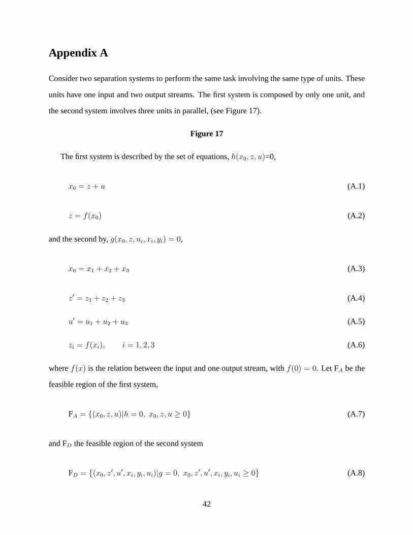
Consider two separation systems to perform the same task involving the same type of units. These
units have one input and two output streams. The first system is composed by only one unit, and
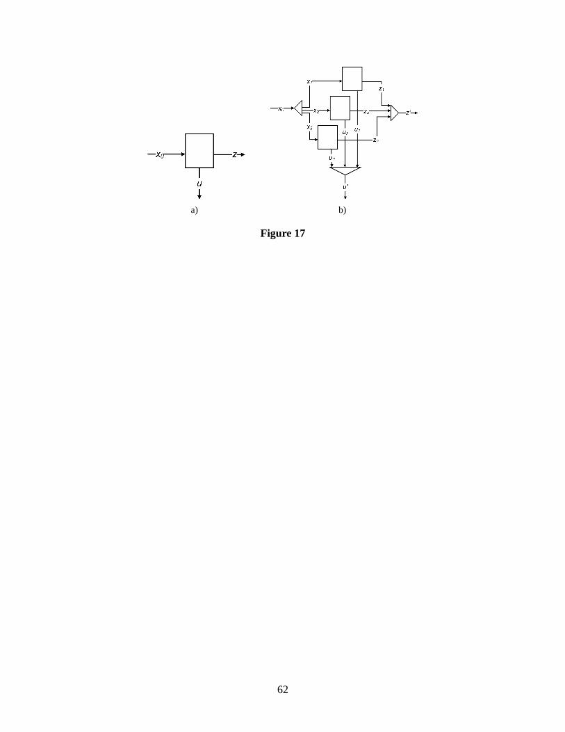
the second system involves three units in parallel, (see Figure 17).
Figure 17
The first system is described by the set of equations,h(x0, z, u)=0,
x0 = z + u (A.1)
z = f(x0) (A.2)
and the second by,g(x0, z, ui, xi, yi) = 0,
x0 = x1 + x2 + x3 (A.3)
z′ = z1 + z2 + z3 (A.4)
u′ = u1 + u2 + u3 (A.5)
zi = f(xi), i = 1, 2, 3 (A.6)
wheref(x) is the relation between the input and one output stream, withf(0) = 0. Let FA be the
feasible region of the first system,
FA = (x0, z, u)|h = 0, x0, z, u ≥ 0 (A.7)
and FD the feasible region of the second system
FD = (x0, z′, u′, xi, yi, ui)|g = 0, x0, z
′, u′, xi, yi, ui ≥ 0 (A.8)
42
Proposition: FA⊆FD for nonlinearf(x).
Proof : Assume that FD⊂FA. This implies∃z ∈ FA, z /∈ FD. First, from Equations A.4 and A.6 we
havez′ =3∑
i=1
f(xi), and forxi 6= 0 andxj = 0, ∀j 6= i it follows thatf(xi) = f(x0) andz′ = z.
However, forxi 6= 0,∀i, z′ is equal or different toz. For linearf(x), z′ = z, but for nonlinearf(x),
it is generally different. Therefore,∃z′ ∈ FD such thatz′ /∈ FA, which contradicts the assumption
FD⊂FA. Hence, FA⊆FD.
Corollary: Applying the above proposition for the blocks of centrifuges in the proposed models,
the feasible region of the aggregated model represents a more constrained region than the region
of the detailed model. Therefore, the aggregated model yields an upper bound on the objective
function.
43
List of Figures
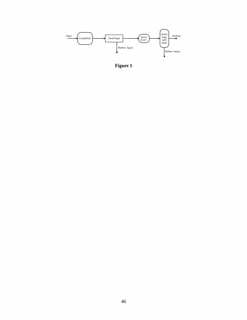
Figure 1 Simplified crystallization separation process with main units.
Figure 2 Proposed superstructure, delimited by the discontinuous line. PEZ- p-xylene enrich-ing zone. CSI and CSII - crystallization networks. CFI, CFII, and CFIII- centrifuge networks.SLDI and SLDII- slurry drum networks. HEH6- heat exchanger.
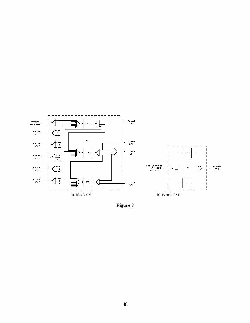
Figure 3 Proposed crystallization networks correspondingto blocks CSI and CSII in Figure 2.IandI2 denote the maximum number of crystallizers in CSI and CSII, respectively.
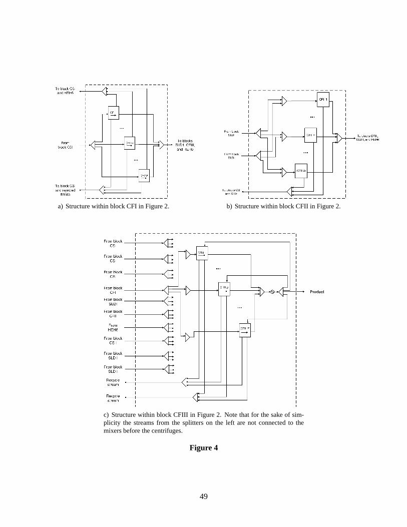
Figure 4 Embedded networks of centrifuges in blocks CFI, CFII, and CFIII in Figure 2.M ,N andP denote the maximum number of units in blocks CFI, CFII, and CFIII, respectively.
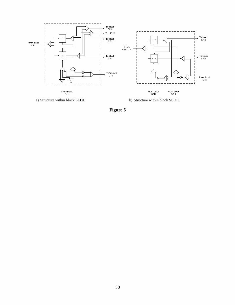
Figure 5 Embedded networks of slurry drums in blocks SLDI andSLDII in Figure 2.
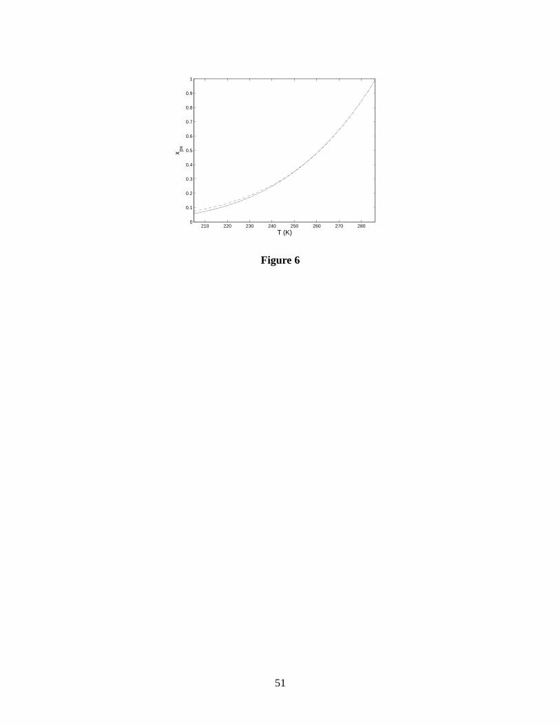
Figure 6 Mole fraction of p-xylene in the solution as a function of the temperature. (-) Usingvan Hoff relationship, (- -) employing cryoscopic constants.?
Figure 7 Second crystallization stage extracted from the proposed superstructure.
Figure 8 Units around the heat exchanger located before the second crystallization stage, ex-tracted from the proposed superstructure.
Figure 9 Set of centrifuges CFI from the detailed model (left) and the respective structure inthe aggregated model (right).
Figure 10 Superstructure for a block of centrifuges from thedetailed model (left) and the re-spective structure in the aggregated model (right).
Figure 11 Superstructure for a block of centrifuges from thedetailed model (left) and the re-spective structure in the aggregated model (right).
Figure 12 Two-level decomposition approach consisting of the solution of an aggregated and de-tailed model.
Figure 13 Partition for the variableFsSX based on the variablesFsSXk andyuk.
Figure 14 Example of the analysis that is made in order to remove streams and mixers from thedetailed model based on the results from the aggregated model.
Figure 15 Optimum flowsheets obtained for a feed stream with 65 wt % p-xylene. CFI, CFII,and CFIII - centrifuges, CRT - crystallizers, SLD - reslurrydrums.
Figure 16 Optima flowsheets obtained for different compositions of p-xylene in the feed stream.
Figure 17 a) System with one unit, and b) system with three units in parallel.
45
Figure 1
46
Figure 2
47
a) Block CSI. b) Block CSII.
Figure 3
48
a) Structure within block CFI in Figure 2. b) Structure within block CFII in Figure 2.
c) Structure within block CFIII in Figure 2. Note that for thesake of sim-plicity the streams from the splitters on the left are not connected to themixers before the centrifuges.
Figure 4
49
a) Structure within block SLDI. b) Structure within block SLDII.
Figure 5
50
210 220 230 240 250 260 270 2800
0.1
0.2
0.3
0.4
0.5
0.6
0.7
0.8
0.9
1
T (K)
x px
Figure 6
51
Figure 7
52
Figure 8
53
a) Detailed model. b) Aggregated model.
Figure 9
54
a) Detailed model. b) Aggregated model.
Figure 10
55
a) Detailed model. b) Aggregated model.
Figure 11
56
Figure 12
57
Figure 13
58
a) Extract from the aggregatedmodel.
b) The streams with zeroflowrate (streams with no labelon the left figure) in the solutionof the aggregated model areremoved.
c) Mixers with one input streamand splitters with one outputstream are removed from thesuperstructure of the detailedmodel.
Figure 14
59
Fig
ure
15
60
a)P
roce
ssfe
edst
ream
with
90w
t%p-
xyle
ne.
b)P
roce
ssfe
edst
ream
with
98w
t%p-
xyle
ne.
Fig
ure
16
61
a) b)
Figure 17
62
List of Tables
Table 1 Boiling and freezing point of each component in the process feed
Table 2 Size of each model for decomposition and simultaneous solution for Case III
Table 3 Best solutions, in terms of objective function, feedflowrate and number of units in eachblock, obtained with two different initialization approaches
Table 4 Results at each iteration level for Case I
Table 5 Results at each iteration level for Case II
Table 6 Results at each iteration level for Case III
Table 7 Optimum results for the total annual cost, investment and operating percentage costsfor each case


![ENVIRONMENTAL CONTAMINANTS … ortho-xylene, 45-70% meta-xylene, 23% para-xylene, and 6-10% ethylbenzene [366]. While o-xylene is recognized as a distinct product in](https://static.documents.pub/doc/80x56/5b4c8c857f8b9afe4d8b9be3/environmental-contaminants-ortho-xylene-45-70-meta-xylene-23-para-xylene-and.jpg)