Page 1
Optimization-based Synthesis
of Hybrid Separation Processes
Von der Fakultat fur Maschinenwesen der
Rheinisch-Westfalischen Technischen Hochschule Aachen
zur Erlangung des akademischen Grades eines
Doktors der Ingenieurwissenschaften genehmigte Dissertation
vorgelegt von
Korbinian Kramer
Berichter: Universitatsprofessor Dr.-Ing. Wolfgang Marquardt
Universitatsprofessor Dr.-Ing. Andrzej Gorak
Tag der mundlichen Prufung: 31. Januar 2012
Diese Dissertation ist auf den Internetseiten der Hochschulbibliothek
online verfugbar.
Page 3
FFoorrttsscchhrriitttt--BBeerriicchhttee VVDDII
OOppttiimmiizzaattiioonn--bbaasseeddSSyynntthheessiiss ooffHHyybbrriidd SSeeppaarraattiioonnPPrroocceesssseess
Dipl.-Ing. Korbinian Krämer,Köln
RReeiihhee 33
Verfahrenstechnik
NNrr.. 993344
Berichte aus der
Aachener Verfahrenstechnik - Prozesstechnik
RWTH Aachen University
Page 4
© VDI Verlag GmbH · Düsseldorf 2012Alle Rechte, auch das des auszugsweisen Nachdruckes, der auszugsweisen oder vollständigen Wiedergabe(Fotokopie, Mikrokopie), der Speicherung in Datenverarbeitungsanlagen, im Internet und das der Übersetzung, vorbehalten.Als Manuskript gedruckt. Printed in Germany.ISSN 0178-9503ISBN 978-3-18-393403-4
Krämer, KorbinianOptimization-based Synthesis of Hybrid Separation ProcessesFortschr.-Ber. VDI Reihe 3 Nr. 934. Düsseldorf: VDI Verlag 2012.243 Seiten, 59 Bilder, 78 Tabellen.ISBN 978-3-18-393403-4, ISSN 0178-9503,¤ 73,00 / VDI-Mitgliederpreis ¤ 65,70.Keywords: Process design – Conceptual design – Process optimization – Shortcut method –Rigorous optimization – MINLP – Distillation – Heteroazeotropic distillation – Extraction –Crystallization
Hybrid separation processes offer a great potential for the design of energy-efficient, sustainableseparation processes through a combination of different separation techniques. However, the designof these highly integrated processes is challenging due to the multitude of structural and operativedegrees of freedom. A lack of modeling experience and reliable synthesis methods has sofar hindered the application of these promising designs in industry. It is the scope of this thesis toprovide methodologies which facilitate an efficient and reliable conceptual design of hybridseparation processes. For this purpose, a synthesis framework for the optimization-based design ofhybrid processes is proposed. Powerful shortcut and rigorous evaluation methods for distillation,heteroazeotropic distillation, extraction, crystallization and reactive distillation are developed. Thesemethods are fully algorithmic and computationally efficient in order to allow an optimization -based design of large-scale hybrid processes. The proposed synthesis framework is validatedby industrial case studies.
D 82 (Diss. RWTH Aachen University, 2012)
Bibliographische Information der Deutschen BibliothekDie Deutsche Bibliothek verzeichnet diese Publikation in der Deutschen Nationalbibliographie;detaillierte bibliographische Daten sind im Internet unter http://dnb.ddb.de abrufbar.
Bibliographic information published by the Deutsche Bibliothek(German National Library)The Deutsche Bibliothek lists this publication in the Deutsche Nationalbibliographie(German National Bibliography); detailed bibliographic data is available via Internet athttp://dnb.ddb.de.
Page 5
Vorwort
Die vorliegende Arbeit entstand wahrend meiner Zeit als wissenschaftlicher Mitarbei-
ter an der Aachener Verfahrenstechnik-Prozesstechnik der RWTH Aachen University.
Ich mochte meinem Doktorvater, Herrn Professor Dr.-Ing. Wolfgang Marquardt,
fur die Betreuung und Forderung wahrend dieser Zeit herzlich danken. Seine fachliche
Kompetenz und seine Offenheit gegenuber neuen Forschungsansatzen haben die Basis
fur diese Dissertation gelegt. Fur sein Vertrauen in meine Arbeit und die Moglichkeit
zum eigenstandigen und kreativen Arbeiten bin ich ihm sehr dankbar.
Weiterhin danke ich Herrn Prof. Dr.-Ing. Andrzej Gorak von der Technischen Uni-
versitat Dortmund fur die Ubernahme des Koreferates. Die Kooperation mit Prof.
Gorak im Bereich der Hybridverfahren aus Destillation und Pervaporation habe ich
als sehr angenehm empfunden. Herrn Prof. Dr.-Ing. Andre Bardow mochte ich fur die
Ubernahme des Prufungsvorsitzes danken.
Die offene, familiare und herzliche Atmosphare am Lehrstuhl hat das produktive
Arbeiten ungemein unterstutzt und uber manche Hurde hinweggeholfen. Dafur danke
ich allen Mitarbeitern.
Die enge Kooperation innerhalb der Synthesegruppe hat einen großen Anteil am
Gelingen dieser Arbeit. Sven Kossack, der mir vier Jahre lang gegenuber saß, mochte
ich besonders fur sein Engagement und seine Geduld bei meiner Einarbeitung dan-
ken. Wir haben viel gemeinsam geforscht, diskutiert, publiziert und gelacht. Er hat
nicht nur einen großen Teil zum Erfolg der Dissertation beigetragen sondern auch
zum Spass an der Arbeit. Andreas Harwardt mochte ich fur seine zahlreichen Ideen,
seine Hilfsbereitschaft und die angenehme Zusammenarbeit bei vielen Themen die-
ser Arbeit danken. Mirko Skiborowski, der mich bei der robusten Berechnung von
Phasengleichgewichten unterstutzt hat, sei ebenfalls herzlich gedankt.
Weiterhin mochte ich Akram Avami, mit der ich im Bereich der Naherungsverfah-
ren fur Reaktivdestillation zusammengearbeitet habe, und meinen Diplomarbeitern,
Studienarbeitern und studentischen Hilfskraften fur ihren Beitrag zu dieser Arbeit
danken.
Mein großter Dank gilt meinen Eltern, die schon fruh das Interesse an Wissenschaft
in mir geweckt haben, und meiner Frau Friederike fur ihre Unterstutzung und Liebe.
Koln, im Juli 2012 Korbinian Kramer
III
Page 7
Contents
1 Introduction 1
1.1 Structure of this thesis . . . . . . . . . . . . . . . . . . . . . . . . . . . 3
2 Conceptual design of hybrid separation processes 4
2.1 Flowsheet generation by heuristics . . . . . . . . . . . . . . . . . . . . . 4
2.2 Flowsheet generation by thermodynamic analysis . . . . . . . . . . . . 5
2.3 Shortcut methods . . . . . . . . . . . . . . . . . . . . . . . . . . . . . . 7
2.4 Rigorous optimization . . . . . . . . . . . . . . . . . . . . . . . . . . . 8
2.5 Structural flowsheet optimization . . . . . . . . . . . . . . . . . . . . . 10
2.6 A framework for systematic process synthesis . . . . . . . . . . . . . . . 11
3 Optimization-based synthesis of distillation processes 16
3.1 Shortcut methods for non-ideal distillation . . . . . . . . . . . . . . . . 17
3.1.1 Boundary value method . . . . . . . . . . . . . . . . . . . . . . 18
3.1.2 Pinch-based methods . . . . . . . . . . . . . . . . . . . . . . . . 20
3.1.3 Shortest stripping line method . . . . . . . . . . . . . . . . . . . 25
3.2 Process evaluation with shortcut methods . . . . . . . . . . . . . . . . 26
3.3 Rigorous optimization . . . . . . . . . . . . . . . . . . . . . . . . . . . 27
3.3.1 MINLP column model . . . . . . . . . . . . . . . . . . . . . . . 30
3.3.2 Continuous reformulation of MINLP problems . . . . . . . . . . 35
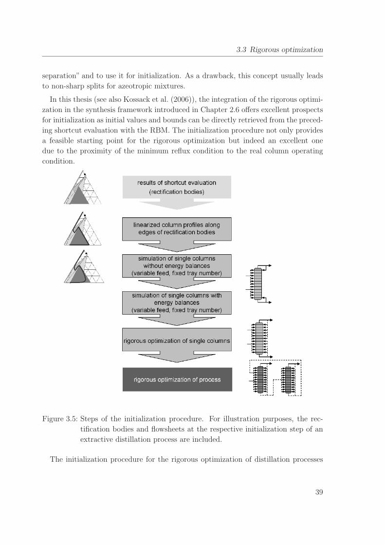
3.3.3 Initialization . . . . . . . . . . . . . . . . . . . . . . . . . . . . . 38
3.3.4 Solution procedure . . . . . . . . . . . . . . . . . . . . . . . . . 40
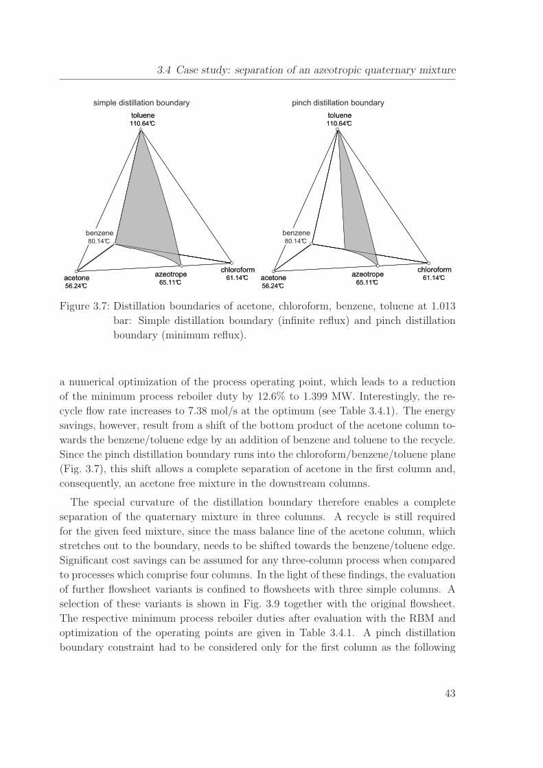
3.4 Case study: separation of an azeotropic quaternary mixture . . . . . . 41
3.4.1 Manual flowsheet generation and shortcut evaluation . . . . . . 42
3.4.2 Automatic generation and evaluation of heat-integrated
flowsheets . . . . . . . . . . . . . . . . . . . . . . . . . . . . . . 46
3.4.3 Rigorous optimization . . . . . . . . . . . . . . . . . . . . . . . 49
3.4.4 Rigorous optimization of a dividing wall column system . . . . . 53
V
Page 8
Contents
3.5 Further case studies . . . . . . . . . . . . . . . . . . . . . . . . . . . . . 55
3.5.1 Pressure swing distillation of an azeotropic quinternary mixture 55
3.5.2 Evaluation of entrainer alternatives for extractive distillation . . 57
3.5.3 Evaluation of internally heat-integrated distillation columns . . 57
3.6 Summary . . . . . . . . . . . . . . . . . . . . . . . . . . . . . . . . . . 58
4 Distillation coupled with decantation 59
4.1 Phase stability test . . . . . . . . . . . . . . . . . . . . . . . . . . . . . 61
4.2 Calculation of tray-to-tray profiles . . . . . . . . . . . . . . . . . . . . . 63
4.3 Application of shortcut methods for non-ideal distillation to
heteroazeotropic distillation . . . . . . . . . . . . . . . . . . . . . . . . 64
4.3.1 Boundary value method . . . . . . . . . . . . . . . . . . . . . . 66
4.3.2 Rectification body method . . . . . . . . . . . . . . . . . . . . . 68
4.3.3 Minimum angle and zero-volume criterion . . . . . . . . . . . . 69
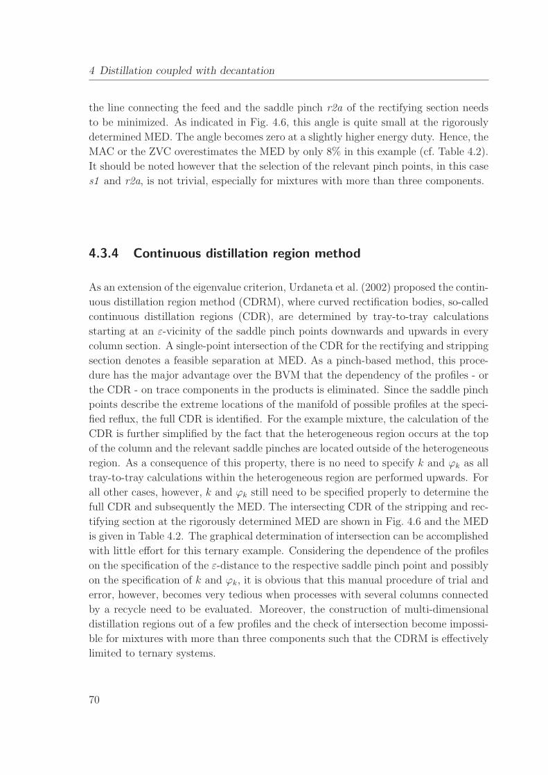
4.3.4 Continuous distillation region method . . . . . . . . . . . . . . . 70
4.3.5 Petlyuk’s methodology . . . . . . . . . . . . . . . . . . . . . . . 71
4.3.6 Shortest stripping line method . . . . . . . . . . . . . . . . . . . 71
4.3.7 Discussion . . . . . . . . . . . . . . . . . . . . . . . . . . . . . . 73
4.4 Feed pinch method . . . . . . . . . . . . . . . . . . . . . . . . . . . . . 73
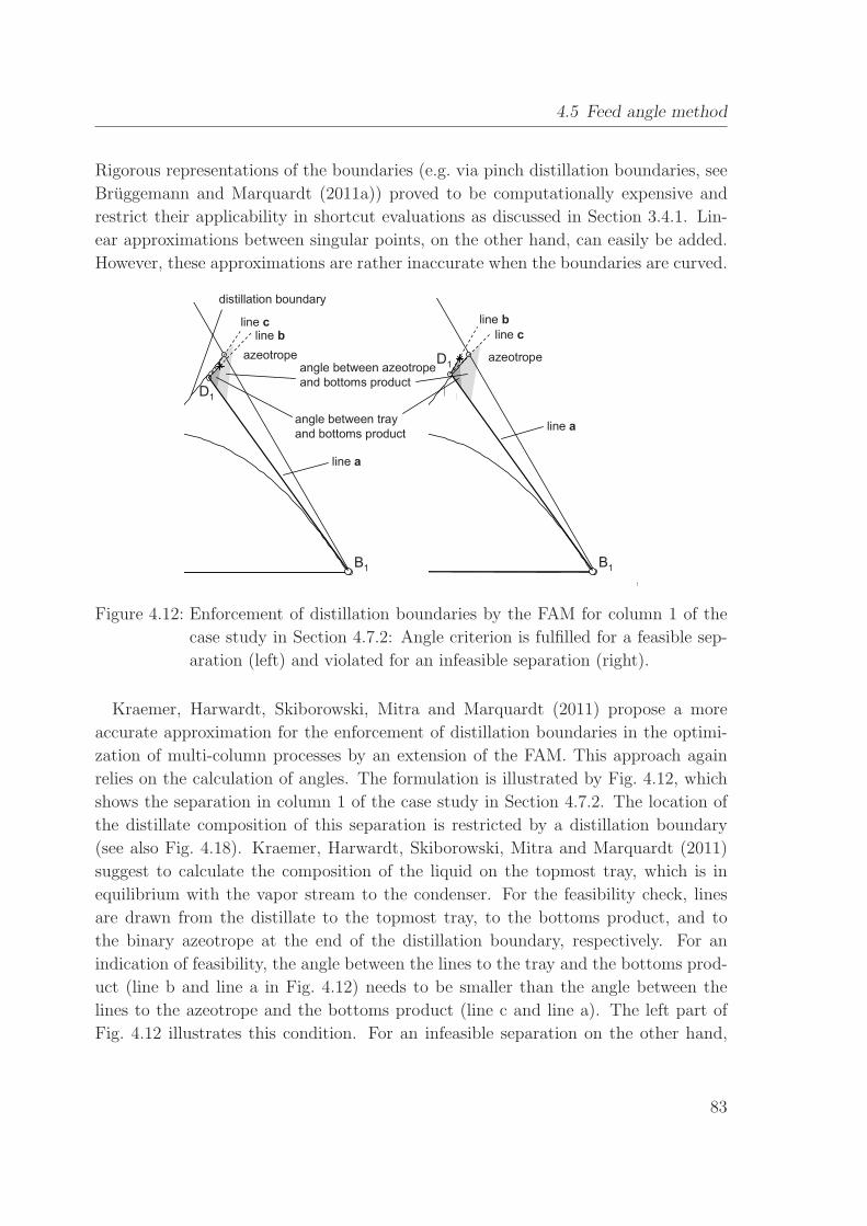
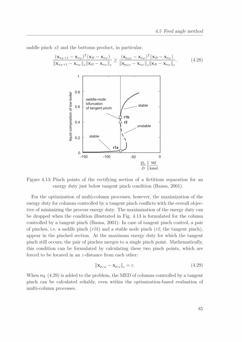
4.5 Feed angle method . . . . . . . . . . . . . . . . . . . . . . . . . . . . . 78
4.5.1 Multi-component mixtures . . . . . . . . . . . . . . . . . . . . . 80
4.5.2 Extension to multi-column processes . . . . . . . . . . . . . . . 82
4.5.3 Separations with a tangent pinch . . . . . . . . . . . . . . . . . 84
4.5.4 Discussion . . . . . . . . . . . . . . . . . . . . . . . . . . . . . . 86
4.6 Rigorous optimization . . . . . . . . . . . . . . . . . . . . . . . . . . . 87
4.6.1 Rigorous column model . . . . . . . . . . . . . . . . . . . . . . . 87
4.6.2 Example . . . . . . . . . . . . . . . . . . . . . . . . . . . . . . . 89
4.7 Case studies . . . . . . . . . . . . . . . . . . . . . . . . . . . . . . . . . 90
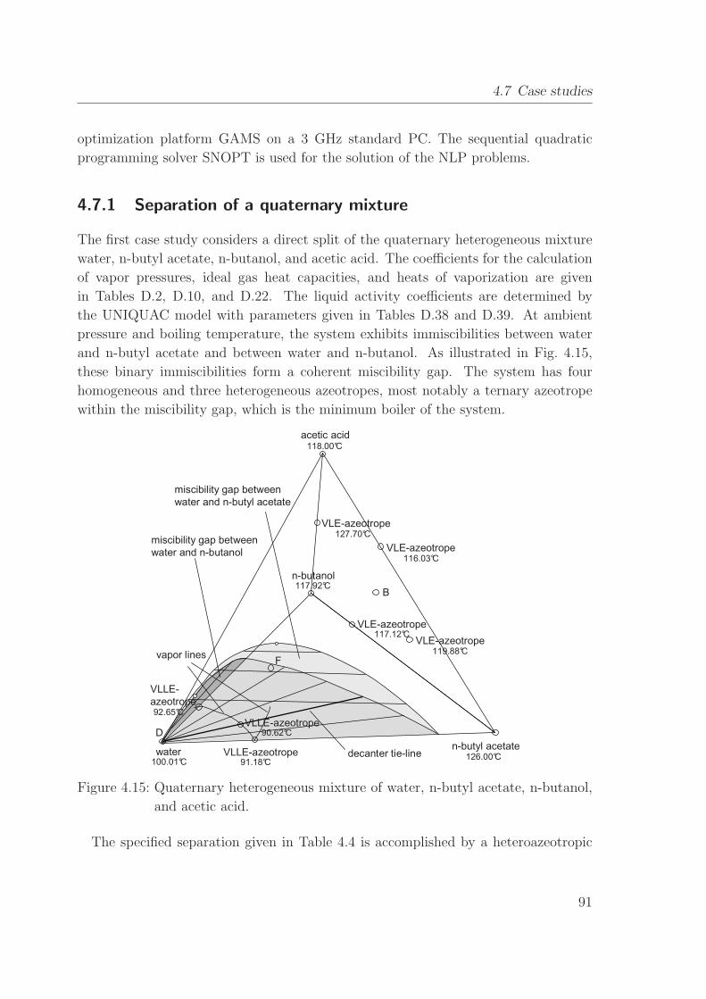
4.7.1 Separation of a quaternary mixture . . . . . . . . . . . . . . . . 91
4.7.2 Complex industrial case study . . . . . . . . . . . . . . . . . . . 95
4.8 Summary . . . . . . . . . . . . . . . . . . . . . . . . . . . . . . . . . . 102
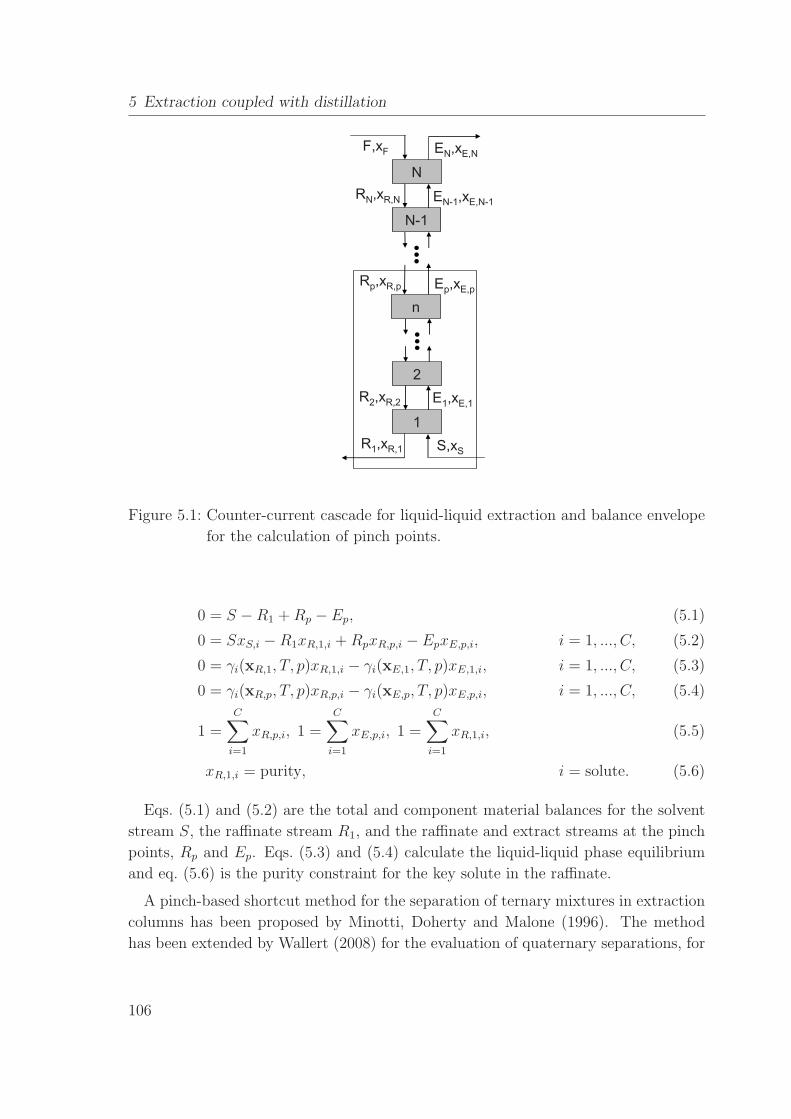
5 Extraction coupled with distillation 104
5.1 Shortcut methods for extraction columns . . . . . . . . . . . . . . . . . 105
5.1.1 Minotti et al.’s shortcut method for ternary mixtures . . . . . . 107
5.1.2 Wallert’s shortcut method for quaternary mixtures . . . . . . . 109
5.1.3 Feed angle method for extraction of multi-component mixtures . 110
5.2 Rigorous optimization of extraction columns . . . . . . . . . . . . . . . 113
VI
Page 9
Contents
5.2.1 Rigorous model . . . . . . . . . . . . . . . . . . . . . . . . . . . 114
5.3 Illustrating examples . . . . . . . . . . . . . . . . . . . . . . . . . . . . 115
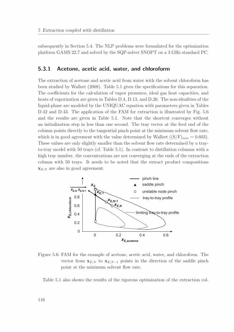
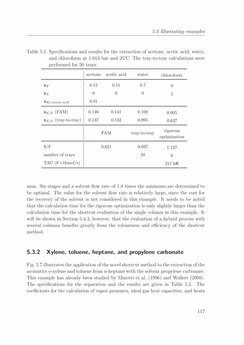
5.3.1 Acetone, acetic acid, water, and chloroform . . . . . . . . . . . . 116
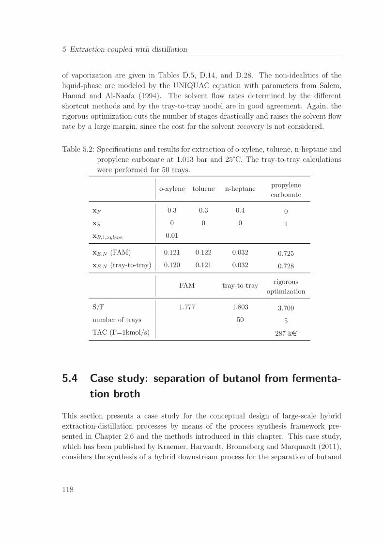
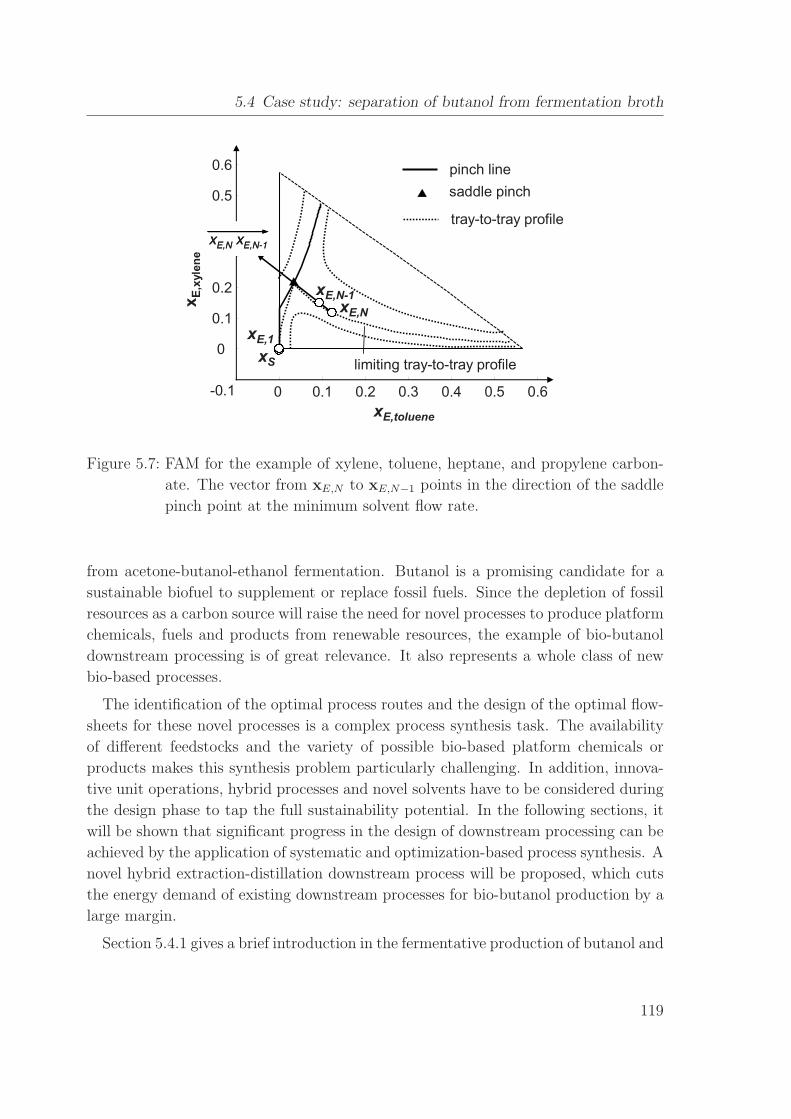
5.3.2 Xylene, toluene, heptane, and propylene carbonate . . . . . . . 117
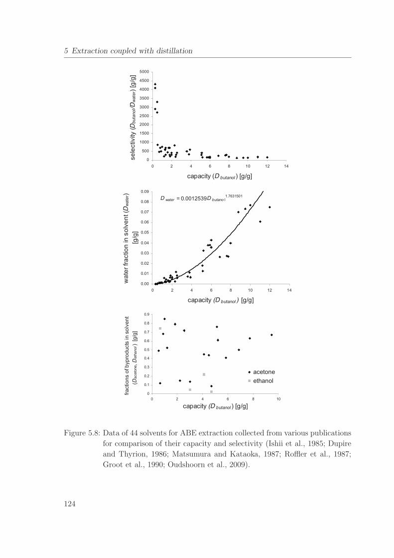
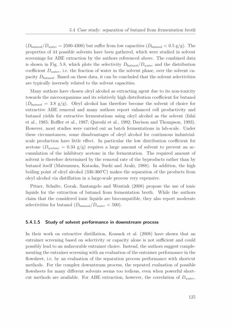
5.4 Case study: separation of butanol from fermentation broth . . . . . . . 118
5.4.1 Fermentative production of butanol from biomass . . . . . . . . 120
5.4.2 A novel solvent for energy-efficient product removal . . . . . . . 128
5.4.3 Shortcut evaluation of downstream process variants . . . . . . . 132
5.4.4 Rigorous optimization of the novel downstream process . . . . . 140
5.4.5 Discussion . . . . . . . . . . . . . . . . . . . . . . . . . . . . . . 143
5.5 Summary . . . . . . . . . . . . . . . . . . . . . . . . . . . . . . . . . . 144
6 Melt crystallization coupled with distillation 146
6.1 Shortcut model of melt crystallization . . . . . . . . . . . . . . . . . . . 147
6.2 Rigorous model of melt crystallization . . . . . . . . . . . . . . . . . . 150
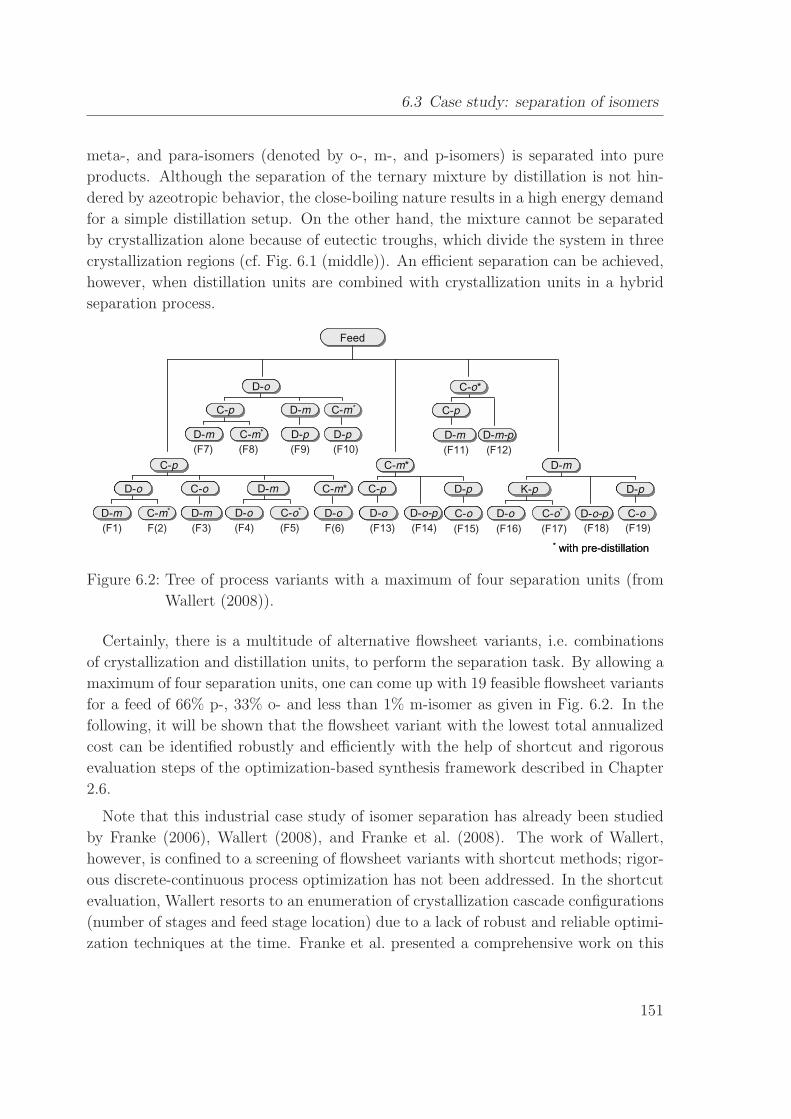
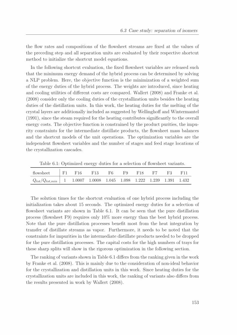
6.3 Case study: separation of isomers . . . . . . . . . . . . . . . . . . . . . 150
6.3.1 Screening of flowsheet variants with shortcut methods . . . . . . 152
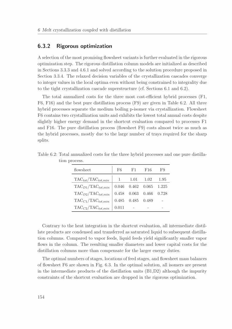
6.3.2 Rigorous optimization . . . . . . . . . . . . . . . . . . . . . . . 154
6.4 Summary . . . . . . . . . . . . . . . . . . . . . . . . . . . . . . . . . . 155
7 Reactive distillation 157
7.1 Shortcut evaluation of reactive distillation . . . . . . . . . . . . . . . . 158
7.2 Feed angle method for reactive distillation . . . . . . . . . . . . . . . . 159
7.2.1 Illustrative examples . . . . . . . . . . . . . . . . . . . . . . . . 160
7.2.2 Higher-dimensional systems and two-feed columns . . . . . . . . 163
7.3 Rigorous optimization of reactive distillation . . . . . . . . . . . . . . . 164
7.4 Summary . . . . . . . . . . . . . . . . . . . . . . . . . . . . . . . . . . 164
8 Conclusions 166
8.1 Topics for further research . . . . . . . . . . . . . . . . . . . . . . . . . 169
8.1.1 Further unit operations . . . . . . . . . . . . . . . . . . . . . . . 169
8.1.2 Approximation of distillation boundaries . . . . . . . . . . . . . 170
8.1.3 Model-based experimental analysis (MEXA) for process design . 170
8.1.4 Software development . . . . . . . . . . . . . . . . . . . . . . . 171
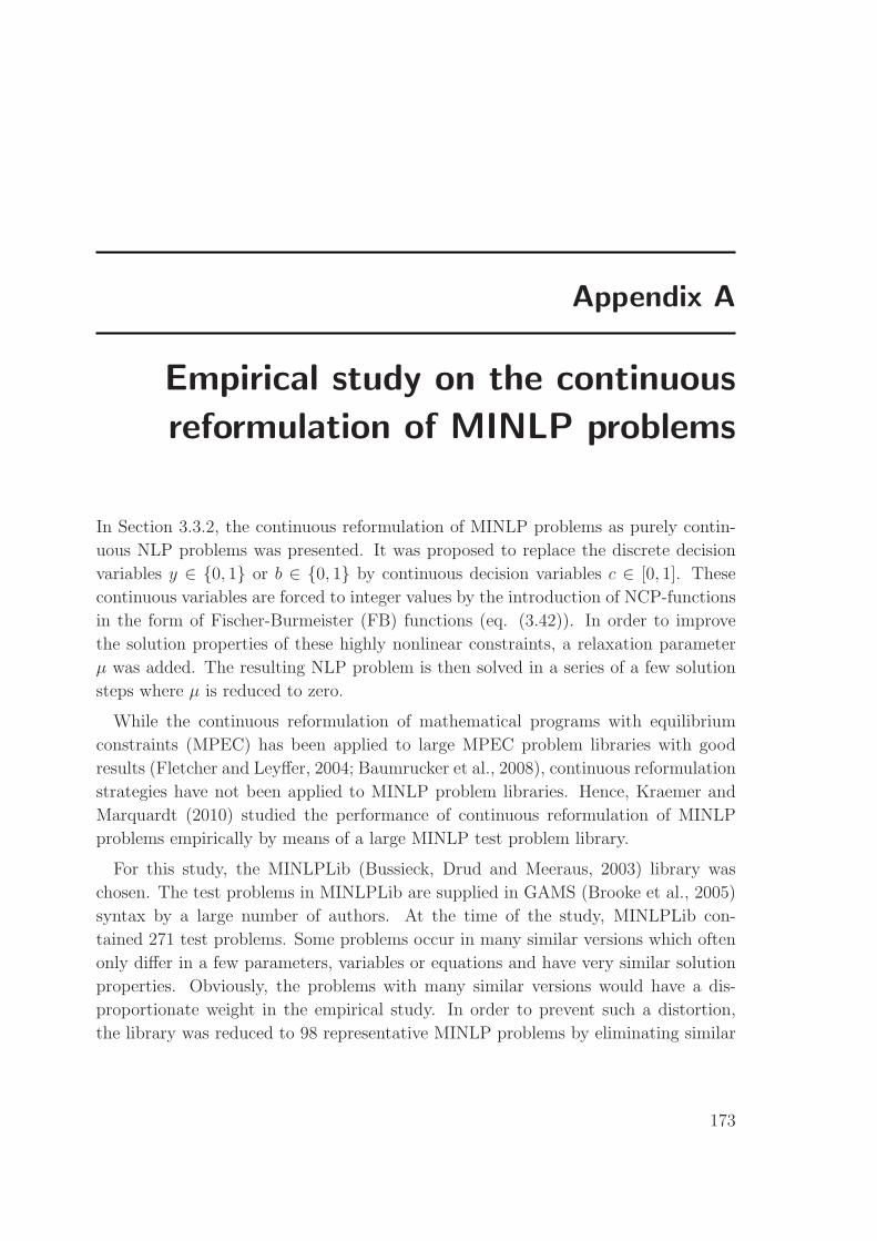
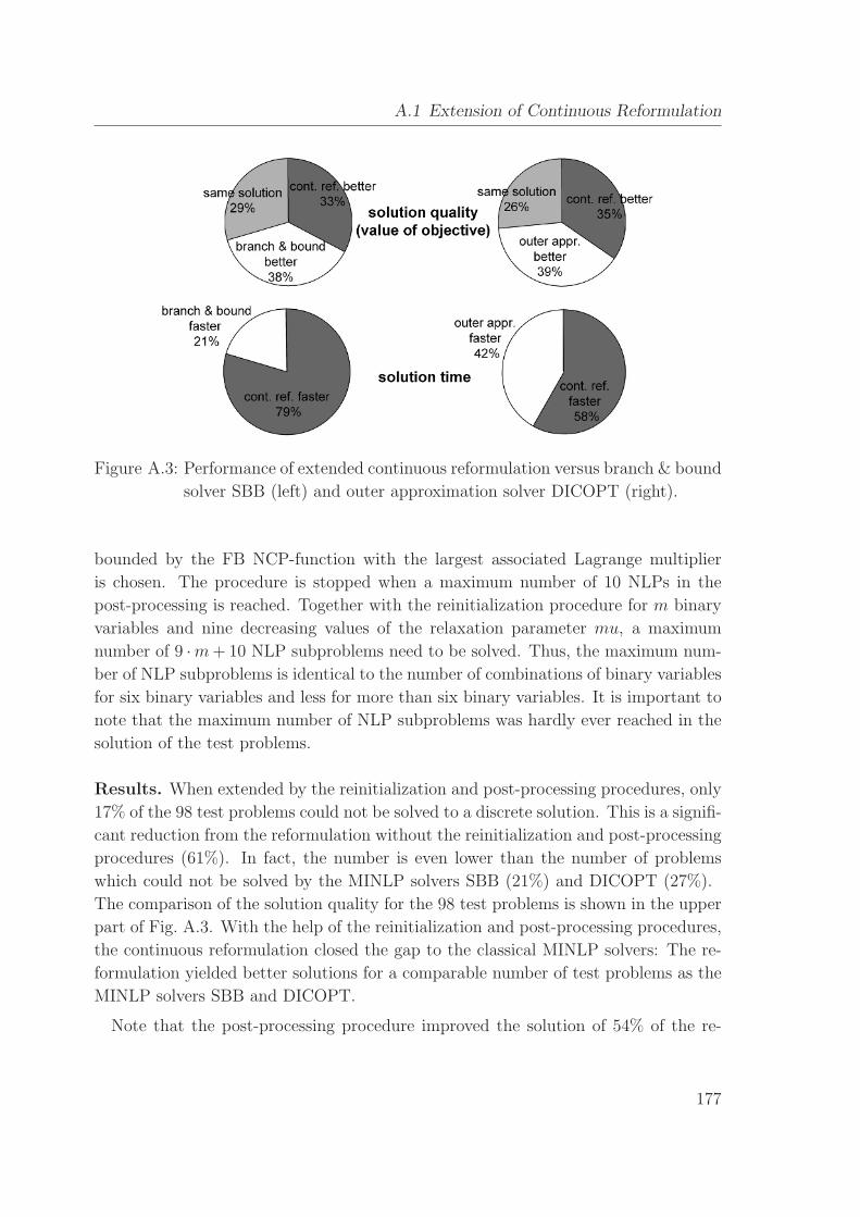
A Empirical study on the continuous reformulation of MINLP problems 173
A.1 Extension of Continuous Reformulation . . . . . . . . . . . . . . . . . . 175
A.2 Summary . . . . . . . . . . . . . . . . . . . . . . . . . . . . . . . . . . 179
VII
Page 10
Contents
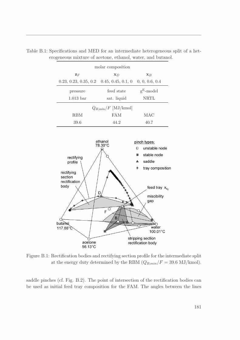
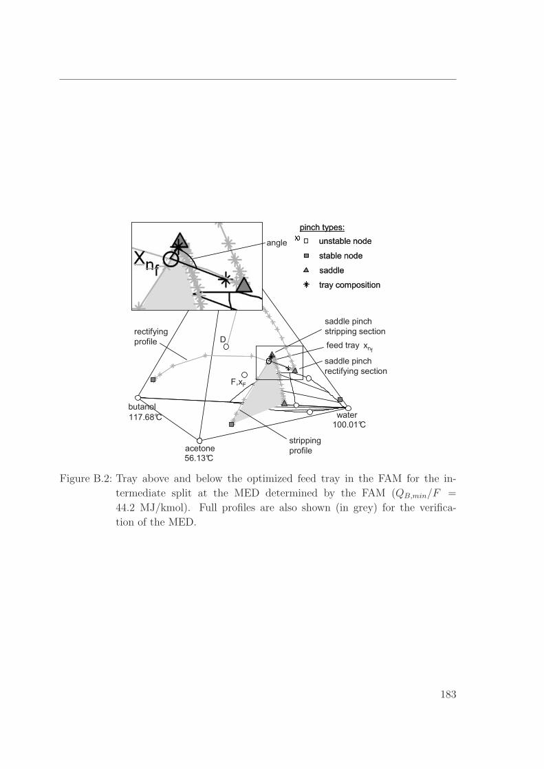
B FAM for intermediate splits without feed pinch 180
C Sizing and costing functions 184
D Physical Property Calculation 187
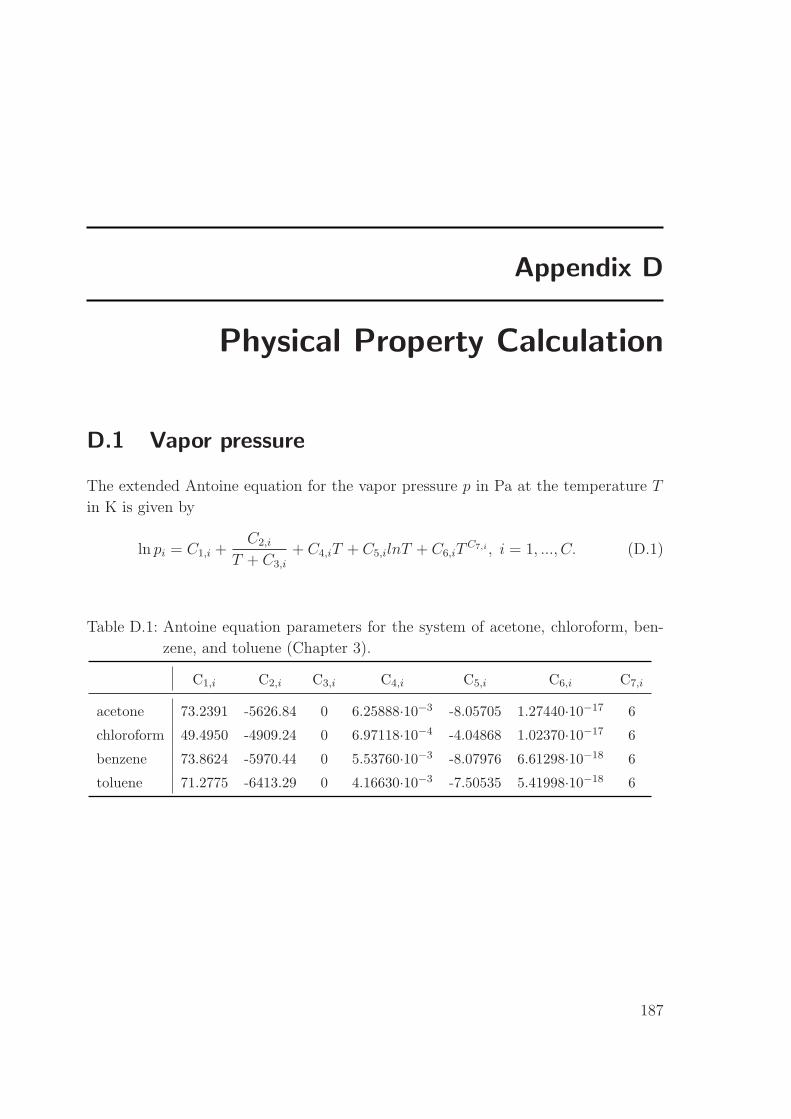
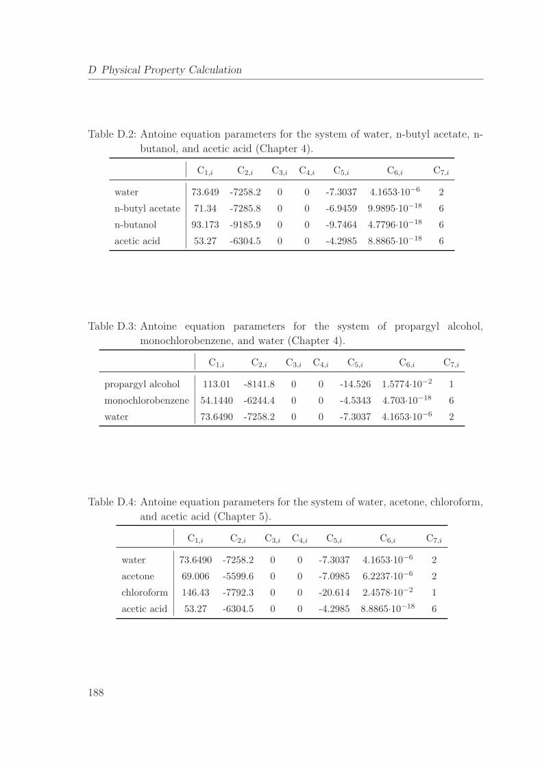
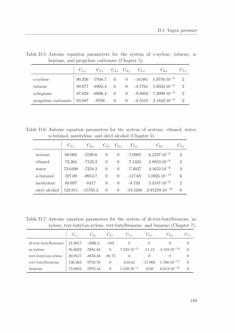
D.1 Vapor pressure . . . . . . . . . . . . . . . . . . . . . . . . . . . . . . . 187
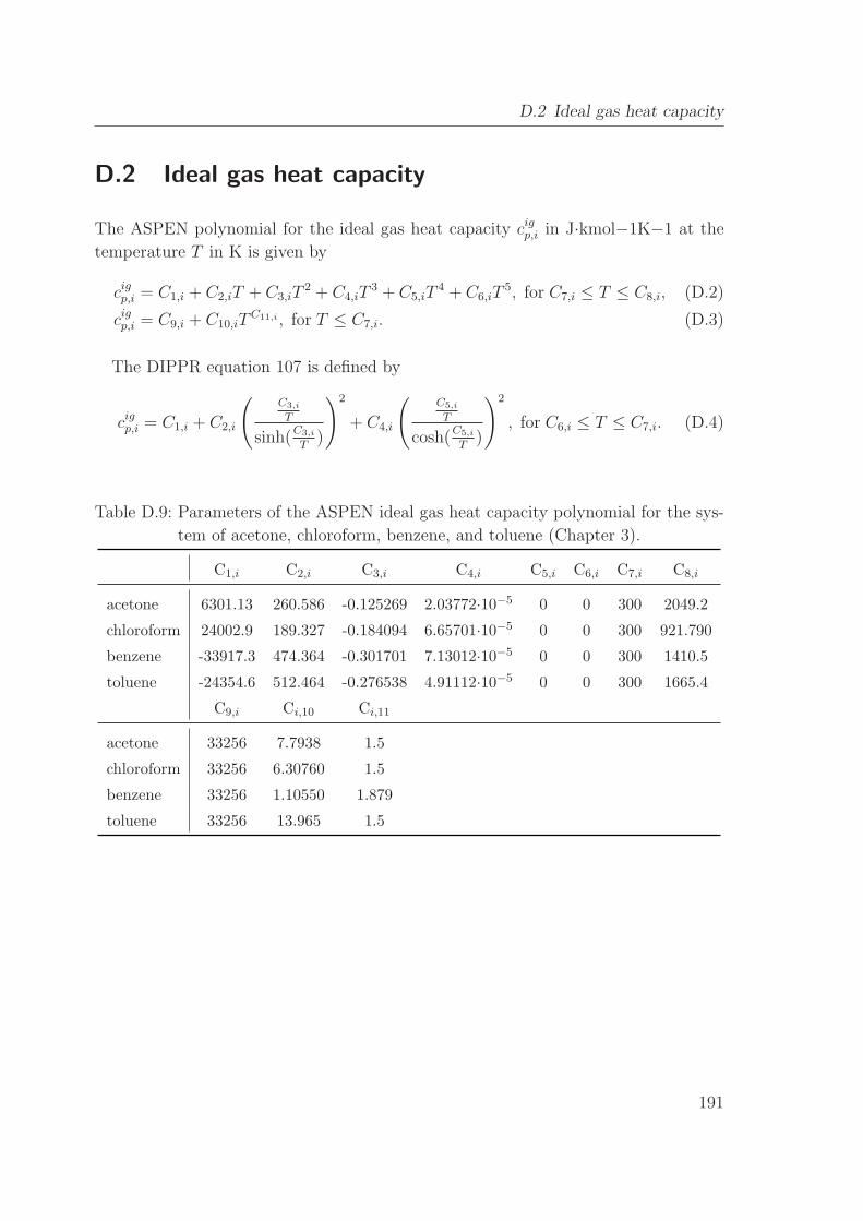
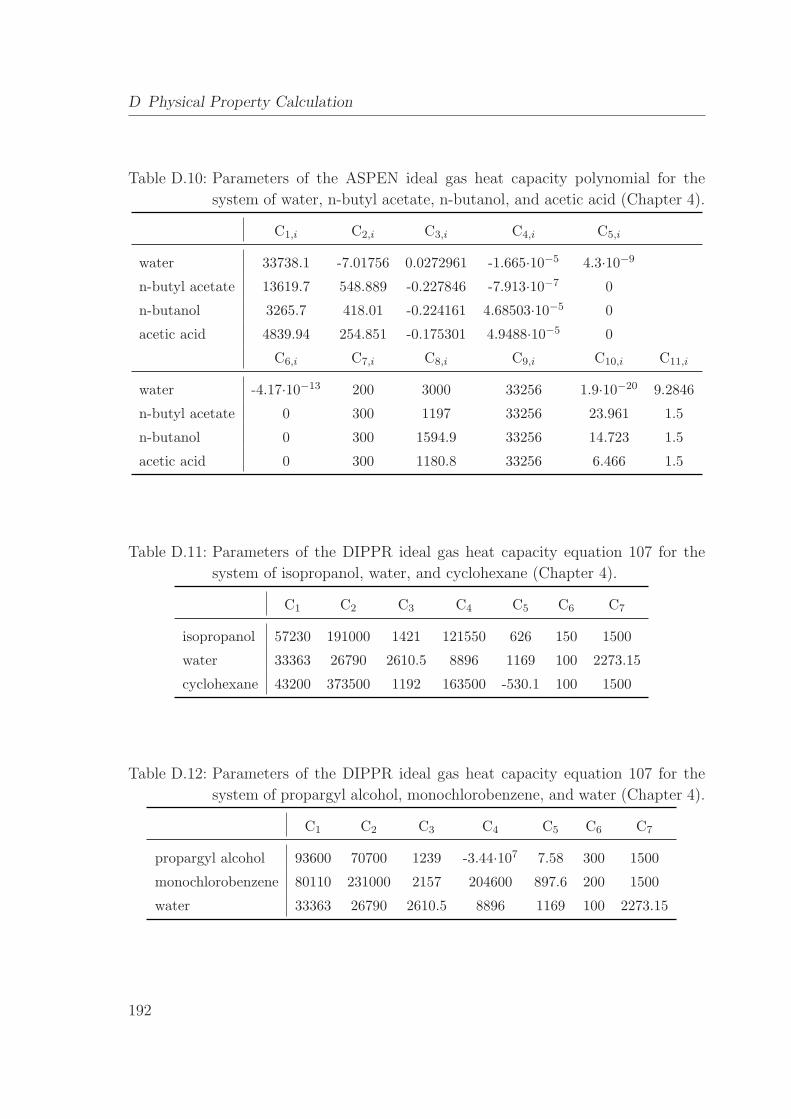
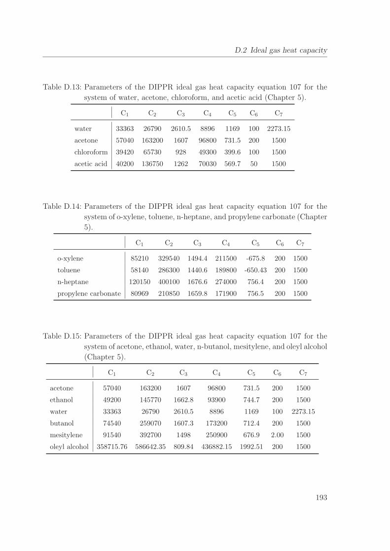
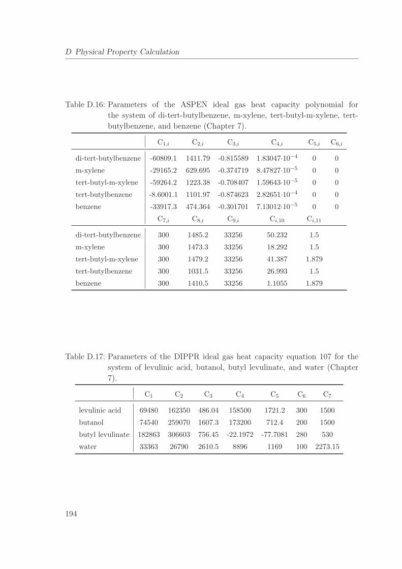
D.2 Ideal gas heat capacity . . . . . . . . . . . . . . . . . . . . . . . . . . . 191
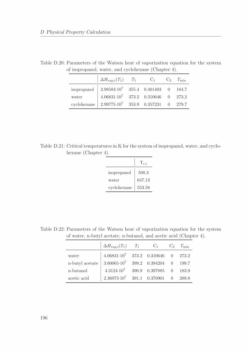
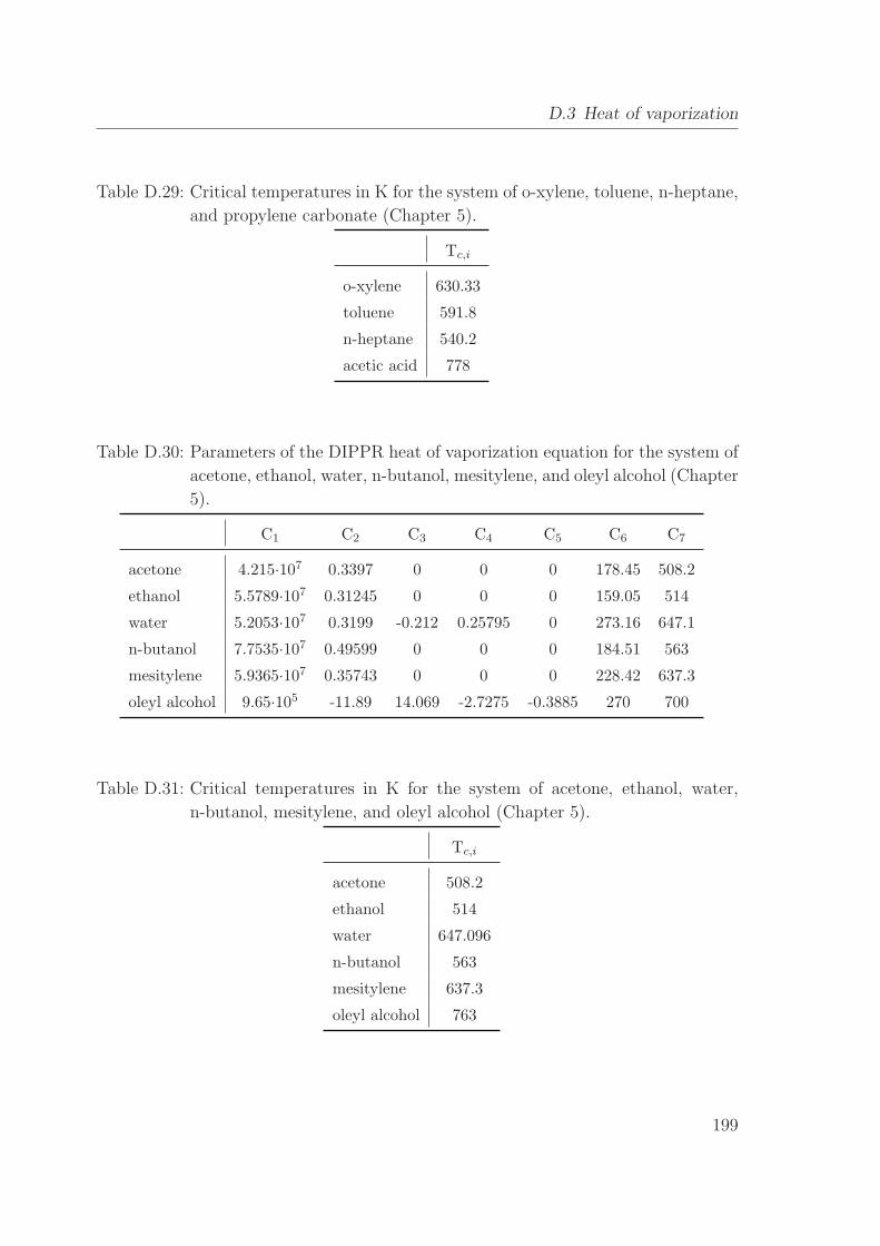
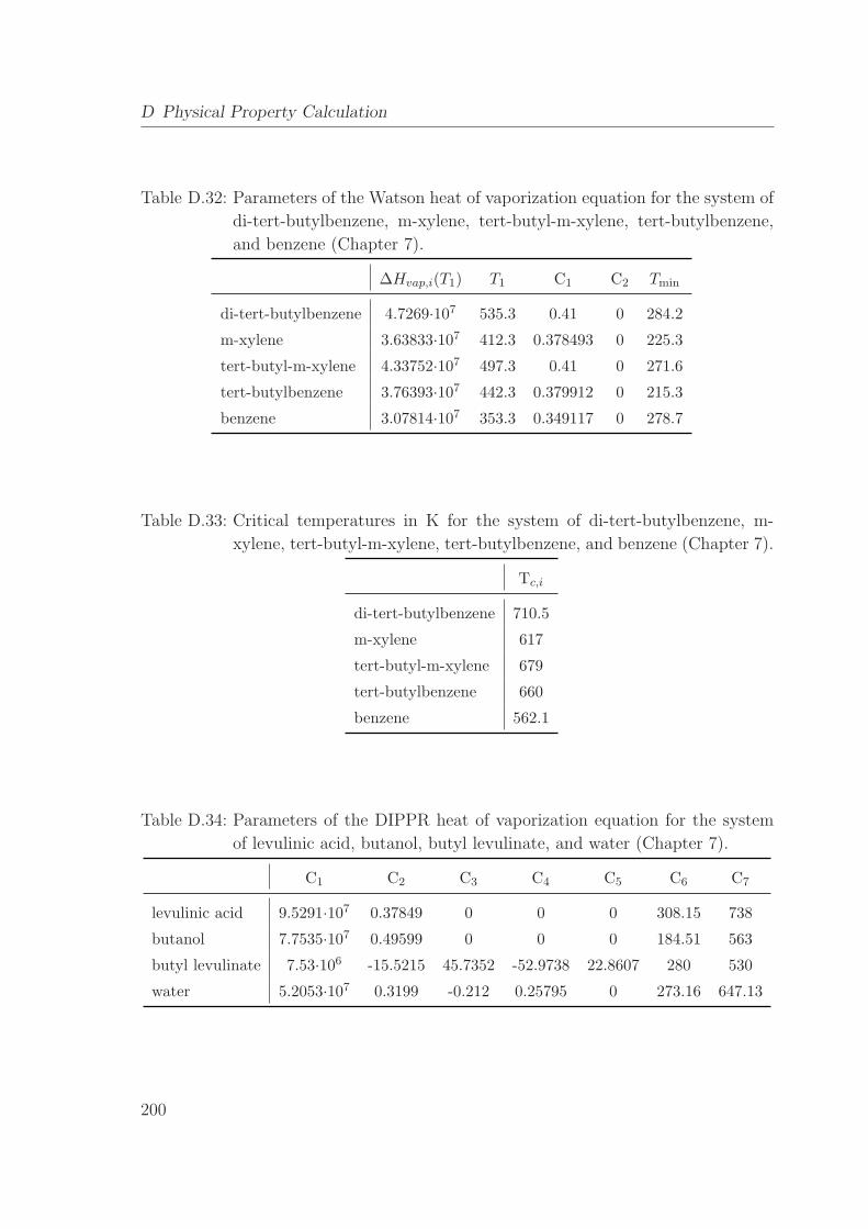
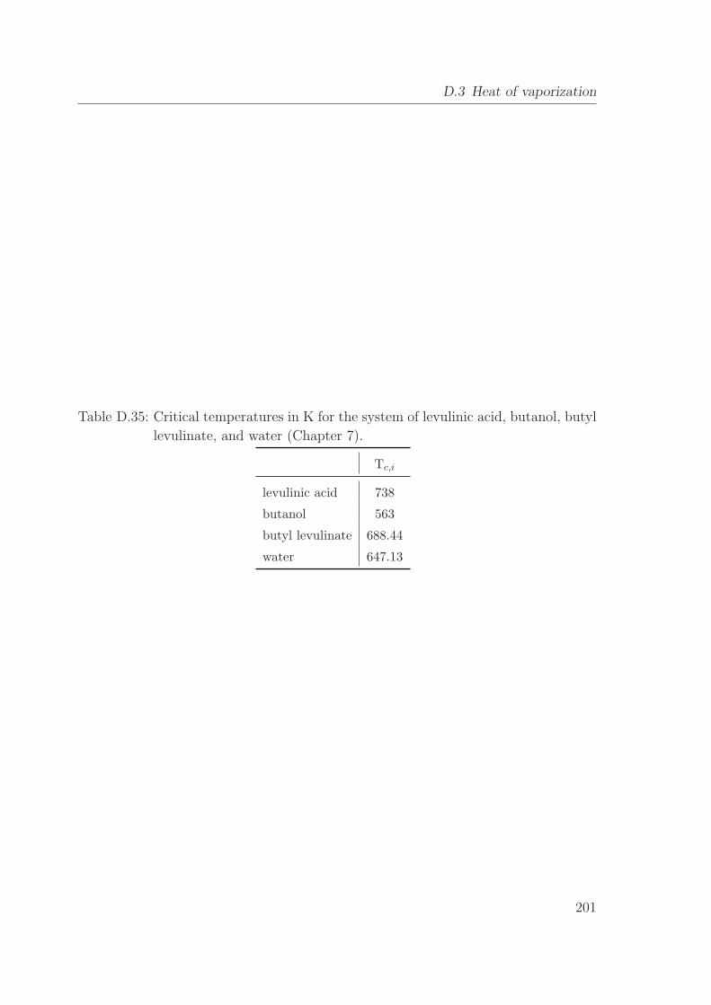
D.3 Heat of vaporization . . . . . . . . . . . . . . . . . . . . . . . . . . . . 195
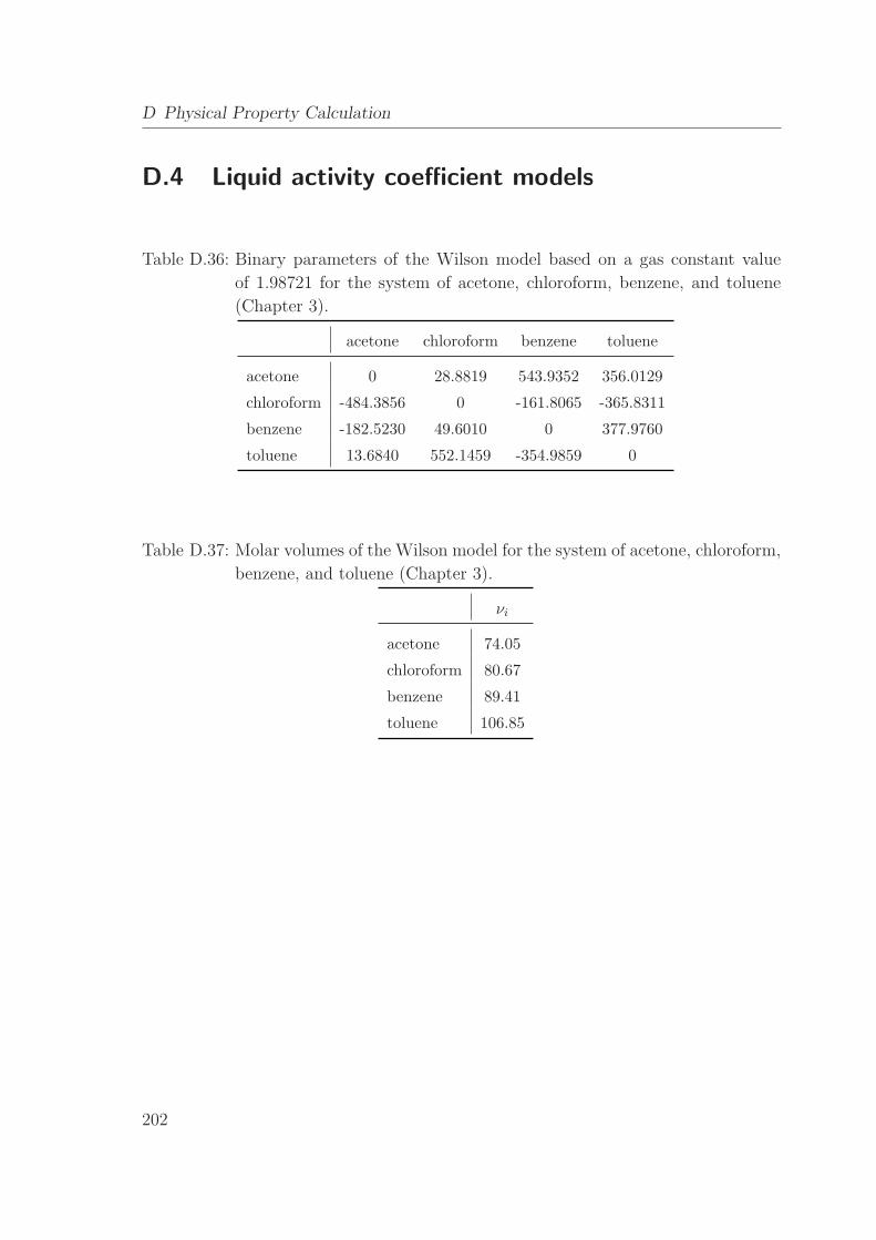
D.4 Liquid activity coefficient models . . . . . . . . . . . . . . . . . . . . . 202
Bibliography 211
VIII
Page 11
Notation
A area [m2]
B bottoms stream [mol/s]
b binary variable [-]
C number of components, coefficient, cost [-],[-],[e]c continuous variable [-]
cp heat capacity [J/kmol·K]
D distillate stream, diameter, distribution coefficient [mol/s],[m],[g/g]
E extract stream, reaction extent [mol/s]
F feed stream [mol/s]
FG F-factor [Pa0.5]
fc capital charge factor [1/a]
H height [m]
H0 height of liquid distributors [m]
h enthalpy [J/mol]
∆Hvap enthalpy of vaporization [J/kmol]
∆Hm enthalpy of fusion [J/mol]
K equilibrium constant, number of feed streams [-]
K crystallization effort [-]
k heat transfer coefficient, [W/m2·K]
Keq chemical equilibrium constant [-]
L liquid stream, length [mol/s],[m]
M molar weight, proportionality constant [g/mol],[-]
m binary decisions, collinearity factor [-]
MF module factor [-]
MPF material and pressure factor [-]
m mass flow [t/h]
N number of trays [-]
n normal vector [-]
IX
Page 12
Notation
Ncol number of column trays [-]
Nreac number of reactions [-]
q feed state [-]
Q energy [W]
p pressure [bar]
P number of pinches [-]
R gas constant [J/mol·K]
R reflux/reboil ratio, raffinate stream, residue melt stream [-],[mol/s]
r chemical equilibrium, heat of vaporization [-],[J/mol]
rf freezing ratio [-]
S side stream, solvent stream, solid stream [mol/s]
T temperature [K]
t time [s]
ta annual operation time [h/a]
Tc critical temperature [°C]Tm melting temperature [°C]TAC total annualized cost [e/a]V vapor stream, volume [mol/s],[m3]
w velocity [m/h]
x liquid composition [-]
x feed point for ZVC/MAC [-]
y vapor composition, binary variable [-]
z total composition, solid composition [-]
z0 reference state [-]
α angle [°]γ activity coefficient [-]
ϵ load factor [-]
λ continuation parameter [-]
µ relaxation parameter [-]
ν stoichiometric coefficient [-]
ν molar volume [m3/mol]
ϱ density [kg/m3]
τ binary interaction parameter [-]
φ phase distribution [-]
X
Page 13
Notation
Superscripts
0 on vapor line
ig ideal gas
L liquid
V vapor
∞ infinite dilution
I,II liquid phases
Subscripts
B bottom, reboiler, stripping section
C cooling
c column
cap capital
col column
con condenser
cool chilled water (5°C)cryst crystallization
cw cooling water
D distillate, condenser, rectifying section
dec decanter
E extract
e eutectic trough
f feed tray
F feed
FP feed pinch point
H heating
hex heat exchanger
i component, counter
ic crystallizing component
int column internals
j counter, component, reaction
k feed stream, last heterogeneous tray
l liquid
XI
Page 14
Notation
max maximum, last
min minimum
n tray number
op operating
p pinch
R raffinate, residue melt
r reflux
reb reboiler
S side stream, solvent
s column shell, solids
SP relevant saddle pinch points
steam steam
T trays
t tanks
tot total
Sets
E set of eutectic troughs
I set of components
Ie set of two isomers at binary eutectic points
P set of pinch points
XII
Page 15
Kurzfassung
Hybride Trennverfahren bieten durch die Verschaltung unterschiedlicher Grundoper-
ationen Vorteile gegenuber herkommlichen Trennverfahren hinsichtlich der Energieef-
fizienz und der Uberwindung von Trenngrenzen. Somit ermoglicht der Einsatz von
Hybridprozessen eine entscheidende Reduzierung des energetischen und apparativen
Aufwands fur die Auftrennung azeotroper und engsiedender Mehrkomponentengemis-
che.
Trotz der inharenten Vorteile der Hybridverfahren werden diese bisher nur sehr
begrenzt in der Industrie eingesetzt. Ein entscheidender Grund hierfur liegt in der
fehlenden Modellierungserfahrung. Zudem wird die Komplexitat des Prozessentwurfs
durch die aus der Verschaltung der Grundoperationen resultierenden Vielzahl an
strukturellen und operativen Freiheitsgrade deutlich erhoht. Daraus ergibt sich eine
Mannigfaltigkeit an denkbaren Prozessvarianten, die im Prozessentwurf hinsichtlich
Machbarkeit und wirtschaftlichem Potenzial untersucht werden mussen.
Zielsetzung dieser Arbeit ist daher die Entwicklung leistungsfahiger Modellierungs-
werkzeuge fur den Entwurf hybrider Trennverfahren, die den Zeitaufwand und die
Komplexitat der Prozesssynthese reduzieren und damit entscheidend zur Akzeptanz
hybrider Prozesse beitragen konnen. Der Prozessentwurf soll dabei systematisch und
mit Hilfe von rein algorithmischen Methoden erfolgen, die eine Anwendung von Op-
timierungsalgorithmen erlauben. Nur auf diese Weise kann ein effizienter Entwurf
optimaler Hybridprozesse fur nicht-ideale Gemische mit beliebiger Komponentenzahl
erzielt werden.
Die Entwicklung der Entwurfsmethoden in dieser Arbeit basiert auf der System-
atik eines in Vorgangerarbeiten entwickelten Syntheserahmenwerks, das aber bisher
nur fur rein destillative Trennprozesse angewandt werden konnte. Dieses Rahmen-
werk begegnet der Komplexitat des Prozessentwurfs durch eine mehrstufige Vorge-
hensweise mit schrittweise erhohtem Detaillierungsgrad der Modellformulierungen.
Dabei wird die Dimensionalitat der Enwurfsprobleme durch die sukzessive Elim-
XIII
Page 16
inierung von Losungsvarianten reduziert. Im ersten Schritt, der Variantengenerierung,
werden Prozessvarianten fur das zu trennende Gemisch generiert. Diese Fließbildvari-
anten werden im zweiten Schritt mit robusten und effizienten Naherungsverfahren
hinsichtlich Machbarkeit und Energiebedarf evaluiert. Im dritten Schritt wird dann
eine Auswahl erfolgversprechender Varianten mit rigorosen Modellen hinsichtlich der
Gesamtkosten optimiert, um schließlich die beste Trennsequenz am optimalen Be-
triebspunkt zu erhalten.
In der vorliegenden Arbeit wird dieses Syntheserahmenwerk erweitert, so dass die
Entwurfsmethodik auch fur Hybridprozesse angewandt werden kann, in denen Destil-
lation mit Dekantierung, Extraktion, Kristallisation oder Reaktion kombiniert wird.
Zu diesem Zweck wurden leistungsfahige Naherungsverfahren fur die Evaluierung
von Heteroazeotropdestillation, Extraktion, Kristallisation und Reaktivdestillation
entwickelt. Weil diese Naherungsverfahren rein algorithmisch sind, kann die Evaluier-
ung von Prozessfließbildern in eine Optimierungsaufgabe uberfuhrt werden, die einen
effektiven Vergleich alternativer Varianten am optimalen Betriebspunkt erlaubt. Dank
der numerischen Effizienz der Nahrungsverfahren betragt die Rechenzeit fur die Min-
imierung des Energiebedarfs von Trennprozessen mit mehreren Apparaten und Ruck-
fuhrungen nur wenige Sekunden.
Eine zentrale Aufgabe der vorliegenden Arbeit war zudem die Formulierung von
gemischt-ganzzahligen Optimierungsproblemen basierend auf rigorosen Stufenmod-
ellen fur alle betrachteten Trennoperationen. Anhand dieser Modelle konnen im drit-
ten Schritt des Rahmenwerks Informationen uber die optimalen Apparatekonfigura-
tionen und die minimalen Betriebs- und Investitionskosten gewonnen werden. Die Lo-
sungseigenschaften dieser komplexen Optimierungsprobleme konnten durch die Initial-
isierung mit den Ergebnissen der naherungsweisen Evaluierung und die kontinuierliche
Reformulierung des gemischt-ganzzahligen Problems entscheidend verbessert werden.
Der Entwurf hybrider Trennprozesse anhand des entwickelten Syntheserahmenwerks
wird an zahlreichen, zum Teil großtechnischen Fallbeispielen demonstriert. Dabei
werden Gemische mit mehr als drei Komponenten und Probleme aus der indus-
triellen Praxis betrachtet. Es wird gezeigt, das der optimierungsbasierte Entwurf im
vorgestellten Rahmenwerk zu energieeffizienteren und kostengunstigeren Prozessen im
Vergleich zu konventionellen Losungen fuhren kann.
XIV
Page 17
Chapter 1
Introduction
The widely predicted shortage of natural carbon resources will not only affect the
availability of fuels for transportation but also the availability of raw materials for
the production of basic chemicals. Alternative fossil fuels like natural gas and coal
as well as renewable resources, i.e. biomass, are being evaluated as carbon source for
the existing chemical value-adding chains. The expected propagation of bio-based
processes will induce a shift from known production routes to novel routes based
on water-rich feedstock, from gas-phase to liquid-phase reactions, from hot to cold
downstream processes, from low- to high-viscous media, and from conventional to
novel solvents (Marquardt, Harwardt, Hechinger, Kraemer, Viell and Voll, 2010).
Ultimately, the design of new sustainable processes based on these new carbon sources
will be necessary, even for basic chemicals with mature production routes. As a
consequence, an increased interest in methods and tools for robust and efficient process
synthesis is expected as well.
Distillation, which is still the major separation technique in chemical engineering,
will remain essential in many separation processes for the purification of reaction prod-
ucts. Unlike other techniques like membrane separation or chromatography, batch
and continuous distillation are very mature technologies and provide high separation
volumes and purities. Additional advantages of distillation are the low capital invest-
ment, the operational flexibility, and the low operational risk. However, distillation
columns are very energy-intensive unit operations, which consume about 95% of the
total separation energy used in the refining and chemical processing industries, or
about 20% of the U.S. manufacturing energy use (Eldridge, Seibert, Robinson and
Rogers, 2005).
Many distillation processes can be made more energy-efficient by the application
1
Page 18
1 Introduction
of heat integration. Possibilities include heat exchange between process reboilers and
condensers (cf. Section 3.4.2), vapor recompression, and internally heat-integrated
columns (cf. Section 3.5.3). Yet, when distillation boundaries or low relative volatil-
ities complicate distillation, it is desirable to substitute distillation with unit opera-
tions operating at low temperature levels like extraction, crystallization, adsorption,
or membrane separation, if possible. These “cold separation techniques” are particu-
larly advantageous for the separation of products from highly diluted reactor effluents
such as fermentation broths. Still, distillation remains essential in many applications
due to the limitation of these alternatives by separation boundaries, the lack of suit-
able solvents and equipment, or the requirement of high purities and volumes. Hence,
the most effective way to save energy is often to augment distillation with alternative
separation technologies in a hybrid separation process. In general, hybrid separation
processes are characterized by the combination of two or more different unit opera-
tions, which contribute to the same separation task by different physical separation
principles. Thus, separation boundaries or inefficiencies of a single separation mech-
anism can be overcome. If applied correctly, hybrid processes offer significant cost
savings and allow the cost-efficient (bio)chemical synthesis of new products.
Examples for the successful implementation of hybrid processes can be found in
the work of Franke (2006). He reviews processes, where distillation is combined with
decantation, absorption, adsorption, extraction, crystallization, and membrane sepa-
ration, as well as hybrid processes which do not rely on distillation. In their report on
research opportunities for energy reduction, Eldridge et al. (2005) identify the highest
potential for hybrid processes which combine distillation with adsorption, extraction,
or membrane separation. Fewer opportunities with significant energy-savings poten-
tial were identified for absorption and crystallization.
Despite of the inherent advantages of hybrid separation processes, they are not sys-
tematically exploited in industrial applications (Eldridge et al., 2005). A major reason
is rooted in the complexity of the synthesis of these highly integrated processes. The
combination of unit operations leads to a multitude of structural and operative de-
grees of freedom, i.e. a multitude of alternative process variants and possibly entrainer
candidates, which have to be evaluated in order to identify feasible and cost-effective
variants. Considering that the operating points of structurally different process vari-
ants have to be optimized for a meaningful comparison, it is clear that the design
procedure can be very complex and time consuming.
In addition, there is a lack of modeling experience for many unit operations apart
from distillation, which results in an uncertainty towards the design of these unit
operations. Hence, there is a need for powerful modeling and design methodologies
2
Page 19
1.1 Structure of this thesis
to reflect the non-ideal and coupled phenomena of hybrid processes. Likewise, in
their report to the U.S. department of energy, Eldridge et al. (2005) state that the
development of design methodologies for hybrid processes are priority R&D needs to
overcome their economic barriers and gain market acceptance.
1.1 Structure of this thesis
In the light of the above mentioned barriers, it is the scope of this thesis to provide
methodologies which facilitate an efficient and reliable conceptual design of hybrid
separation processes. First, methods for the conceptual design of hybrid separation
processes are reviewed in Section 2. These are grouped into heuristics, thermodynamic
analysis, shortcut evaluation methods, rigorous optimization, and structural flowsheet
optimization.
Subsequently, Section 2.6 presents the process synthesis framework proposed by
Marquardt, Kossack and Kraemer (2008), which combines shortcut evaluation and
rigorous optimization steps for a systematic design of separation processes. This
process synthesis framework has so far been applied predominantly to distillation pro-
cesses (Kossack, Kraemer, Gani and Marquardt, 2008; Kraemer, Kossack and Mar-
quardt, 2009; Kossack, 2010). In this thesis, the extension of the framework to the
optimization-based design of hybrid separation processes will be developed.
Yet before the extension to hybrid processes is addressed, Chapter 3 illustrates
the consistent application of the framework to the design of large-scale distillation
processes. Since distillation is still the backbone of many hybrid processes, powerful
shortcut evaluation and rigorous optimization methods for distillation are essential for
the subsequent extension to hybrid processes. Progress concerning the rigorous opti-
mization of distillation processes is made mainly through the continuous reformulation
and stepwise initialization of discrete-continuous optimization problems.
Chapters 4 to 6 then introduce the extension of the synthesis framework to the
design of hybrid separation processes, where distillation is coupled with decantation,
extraction, and crystallization, respectively. Here, fully algorithmic shortcut and rig-
orous models are developed for the evaluation of the hybrid systems. In order to
demonstrate the effectiveness of the design methods, large-scale industrial case stud-
ies involving multicomponent mixtures are presented in each chapter.
Subsequently, Chapter 7 gives a brief outlook on the extension of the developed
methods to reactive distillation systems. Chapter 8 concludes this thesis and identifies
topics for further research.
3
Page 20
Chapter 2
Conceptual design of hybrid
separation processes
The cost of a chemical process is mainly determined by the first development step,
the conceptual process design. This step is therefore of extraordinary importance and
should be executed carefully. According to Kossack (2010), conceptual design needs
to address three central issues:
• support the invention of conceptual design alternatives,
• assess the feasibility of these conceptual design alternatives, and
• evaluate the alternatives to determine the best of the feasible design alternatives.
General reviews of different tools and design methodologies to answer these ques-
tions are given in the works by Barnicki and Siirola (2004), Li and Kraslawski (2004),
and Westerberg (2004) and in the theses of Bruggemann (2005) and Kossack (2010).
For the design of distillation processes, particularly the latter two works give compre-
hensive synopses of synthesis methods. The following subsections review the literature
on design methodologies proposed for the synthesis of hybrid processes.
2.1 Flowsheet generation by heuristics
In industrial practice, a flowsheet is often pragmatically fixed first using heuristics
from literature, solutions of similar problems, experience and intuition. The most
prominent representative of heuristic methods is the hierarchical design strategy pro-
posed by Douglas (1985, 1988, 1995), which helps to systematize the design procedure.
Expert systems like Jacaranda (Fraga, Steffens, Bogle and Hind, 2000), Prosyn (Kra-
4
Page 21
2.2 Flowsheet generation by thermodynamic analysis
vanja and Grossmann, 1993), or TEAGPERT (Schembecker and Simmrock, 1997) aim
at automating this design step.
The synthesis of hybrid separation processes comprising different separation tech-
niques is significantly more complex than the synthesis of pure distillation processes.
Here, the use of heuristics can contribute significantly towards the identification of
promising flowsheet alternatives. In their well-cited works, Barnicki and Fair (1990,
1992) have developed a knowledge-based, structured expert system for the selection
and sequencing of unit operations for multicomponent separation. Their task-oriented
approach reduces the magnitude of the overall separation synthesis problem by de-
composing the complex design problem into subtasks, for which design guidelines are
given. Wahnschafft, Le Rudulier and Westerberg (1993) suggested a problem decom-
position approach, which also relies on the identification of subtasks and attainable
product regions. In addition, the strategic use of recycles is studied in their work.
In the work by Siirola (1996), the hierarchical approach to process synthesis is fur-
ther elaborated and combined with a means-end analysis, which is an operator-based
state transformation paradigm used in automated goal-orientated problem solving.
Later, Pajula, Seuranen, Koiranen and Hurme (2001) presented a process synthesis
methodology which uses case-based reasoning to benefit from the systematic storing
and reuse of accumulated knowledge. In their work, the phases of reasoning for a sepa-
ration system include the search for creative new solutions by using analogies, the use
of negative cases to exclude some solutions, and the adaptation of cases corresponding
to the separation problem. Harmsen (2004) has gathered the best practices of con-
ceptual process design applied in the chemical process industry in the last 15 years.
He particularly reviews heuristic-based methods for the selection of unit operations
and recycle structures and the integration of units to multi-functional equipment.
Concerning solids processes, a hierarchical procedure for the conceptual design has
been presented by Rajagopal, Ng and Douglas (1992). These authors introduce rules
for the selection of unit operations and equipment configurations. Guidelines for the
determination of design variables and economic trade-offs are also given.
2.2 Flowsheet generation by thermodynamic analysis
The use of heuristics alone may lead to suboptimal flowsheets and cannot substitute
the information gained by thermodynamic insight of the mixture topology. In Section
3.4.1, an example will be presented, where the application of heuristics suggested by
Thong and Jobson (2001) does not lead to the best flowsheet structure. Typically,
the generation of flowsheets is therefore accompanied by some kind of thermodynamic
5
Page 22
2 Conceptual design of hybrid separation processes
analysis to gain information about the feasibility of the unit operations and the flow-
sheet structure. In case of distillation processes, such an analysis usually involves the
graphical inspection of residue curves and distillation boundaries. For extraction, the
shape of the miscibility gap and the location of tie-lines are studied, while the location
of eutectic troughs is inspected for crystallization.
Jaksland, Gani and Lien (1995) and Gani and Constantinou (1996) suggested a
method for the synthesis of hybrid separation processes by means of a systematic
analysis of the relationships between physicochemical properties and the conditions
at which the separation techniques become feasible. The selection of unit operations
for certain separation tasks is then based on the thermodynamic insight gained by
this analysis. Subsequently, Steffens, Fraga and Bogle (1999) proposed a methodol-
ogy for flowsheet generation of hybrid processes by means of a discretization of the
design space. The methodology, which was implemented in Jacaranda (Fraga et al.,
2000), minimizes both the environmental impact and the process costs by multicriteria
optimization. The feasibility of the unit operations is assessed by feasibility indices
taken from Jaksland et al. (1995). Later, Bek-Pedersen, Gani and Levaux (2000)
analyzed the separation driving forces of possible unit operations for the synthesis of
energy-efficient hybrid separation schemes. Based on the information of phase com-
position data only, the method enables the visual determination of optimal separation
sequences. The work of Pressly and Ng (1999) on the other hand focuses on the
consideration of separation boundaries in process synthesis. In conjunction with the
available separation task selection methods, a step-by-step procedure is proposed in
order to generate complete flowsheet alternatives, which allow bypassing both ther-
modynamic and equipment boundaries to achieve a given separations objective.
The generation of flowsheets by heuristics and thermodynamic analysis must be
combined with a quantitative evaluation such that the feasibility and the economic
fitness of the flowsheet alternatives can be assessed. In industrial practice, this is
usually accomplished by repetitive simulation studies, where each flowsheet variant
is evaluated individually. These simulation studies are very time consuming and te-
dious, therefore only a small number of possible flowsheets can be studied. Moreover,
a meaningful ranking of flowsheets can only be accomplished when the variants are
compared at the respective optimal operating points. Commercial sequential-modular
process simulators, however, cannot perform these optimization tasks fully algorith-
mically, such that tedious manual optimization of operating points is required. Hence,
the design of the most cost-effective flowsheet within commercial process simulators
cannot be guaranteed.
6
Page 23
2.3 Shortcut methods
2.3 Shortcut methods
Compared to simulation studies, shortcut methods provide a more efficient way to
assess the feasibility and cost of flowsheet variants. These methods allow an approx-
imate but computationally efficient evaluation of the process economics without the
need for a detailed specification of the units. Paired with representations for sep-
aration boundaries like the pinch distillation boundary, the inspection of feasibility
and the optimization of operating points are also possible. Reviews of the literature
on shortcut methods for the evaluation of the unit operations distillation, extraction,
crystallization, and reactive distillation will be included in Chapters 3 - 7, respectively.
Novel powerful shortcut methods for these unit operations will also be proposed in
these chapters. In the following, literature on the shortcut evaluation of hybrid pro-
cesses is referenced. It needs to be noted that the vast majority of the published works
on the synthesis of hybrid processes, however, concentrate on flowsheet generation by
means of heuristics, case-based reasoning or superstructure optimization (Section 2.5).
A few authors (e.g. Pham, Ryan and Doherty (1989); Ryan and Doherty (1989);
Wasylkiewicz, Kobylka and Castillo (2003)) have published shortcut methods for the
design and evaluation of distillation coupled with decantation (heteroazeotropic dis-
tillation). These works, which are reviewed in detail in Chapter 4, typically resort
to models for two-phase distillation and consider three phases only in the decanter.
Bausa (2001) and Urdaneta, Bausa, Bruggemann and Marquardt (2002) have pro-
posed shortcut methods for the evaluation of heteroazeotropic distillation, which rely
on an accurate identification of vapor-liquid-liquid equilibrium on column trays.
Concerning the combination of distillation with membrane separation, first studies
for the shortcut-based design were presented by Moganti, Noble and Koval (1994),
Stephan, Noble and Koval (1995), and Pettersen and Lien (1995). These authors
analyzed the optimal membrane operating points for a minimization of the number
of distillation trays. In order to reduce complexity, only binary separations have
been considered and the membrane units and distillation columns were optimized
separately. Pressly and Ng (1998) developed a screening method to determine the
break-even costs of distillation-membrane separation processes but also consider only
binary mixtures. Bausa and Marquardt (2000b) studied the evaluation of hybrid
distillation-membrane separation processes by means of algorithmic shortcut methods.
Here, the minimum energy demands of the distillation tasks are determined by the
rectification body method (cf. Section 3.1.2.3). The economic potential of membrane
cascades is described by the minimum membrane area, which is calculated under
the assumption of an infinite number of membrane modules and constant maximum
7
Page 24
2 Conceptual design of hybrid separation processes
temperature. Recently, Caballero, Grossmann, Keyvani and Lenz (2009) developed
a shortcut model for the evaluation of the energy savings potential of distillation
columns combined with vapor membrane systems. They use Underwood’s method
(Underwood, 1948) as distillation shortcut and either a simple black-box model or
an ideal perfect cross-flow model for the membrane system. Ayotte-Sauve, Sorin and
Rheault (2010) present a similar approach, where shortcut models based on the notion
of power of separation are used. Only binary separations are considered.
The energy-efficient design of hybrid extraction-distillation separation processes has
been studied by Lucia, Amale and Taylor (2006). They model the distillation tasks
using their concept of shortest separation lines (cf. Section 3.1.3). A simple extrac-
tion shortcut is applied, since only ternary mixtures are to be separated in the con-
sidered examples. Wallert (2008) extended the shortcut-based evaluation of hybrid
extraction-distillation processes to quaternary mixtures (cf. Section 5.1.2). The ex-
traction shortcut proposed in her work requires an analysis of feasibility by graphical
inspection of the separation topology. In Section 5.1.3, a fully algorithmic shortcut
model for extraction will be proposed, which allows an optimization-based evaluation
of extraction-distillation hybrid processes.
Franke (2006), Wallert (2008), and Franke, Nowotny, Ndocko, Gorak and Strube
(2008) studied the shortcut-based evaluation of hybrid crystallization-distillation pro-
cesses for the separation of close-boiling isomers. Due to the computational efficiency
of their methodology, a manifold of flowsheet variants was ranked based on energy-
efficiency. In Chapter 6, their works will be discussed in more detail and a refinement
of the design methodology will be proposed. Franke (2006) has also studied the design
of hybrid processes comprising crystallization and dissociation extraction units with
the help of shortcut models.
2.4 Rigorous optimization
Shortcut methods rely on various simplifying assumptions and cannot provide infor-
mation about tray numbers or the optimal dimensions of the unit operations. This
information, however, can be gained by a rigorous optimization of units or processes.
These rigorous optimization problems are usually of discrete-continuous nature due
to the cascade-like structure of many unit operations like distillation, extraction, crys-
tallization, and membrane separation. The solution of these problems is therefore
challenging, even when the flowsheet structure of the process is fixed. The conver-
gence properties can be improved by a favorable initialization with shortcut methods.
8
Page 25
2.4 Rigorous optimization
In Chapter 2.6, a process synthesis framework exploiting this property by means of
successive shortcut and rigorous evaluation steps will be described in detail. The fol-
lowing paragraphs give an overview on the literature covering rigorous optimization
of hybrid processes.
Szitkai, Lelkes, Rev and Fonyo (2002), Barakat and Sørensen (2008) and Ski-
borowski, Mhamdi, Kraemer and Marquardt (2012) studied the rigorous optimization
of hybrid processes where distillation is coupled with pervaporation or permeation to
separate binary mixtures or desalinate water. While Szitkai et al. and Skiborowski
et al. optimize the membrane cascades by means of mixed-integer nonlinear program-
ming (MINLP) techniques, Barakat and Sørensen apply genetic optimization algo-
rithms. Buchaly, Kreis and Gorak (2007) also use genetic algorithms for the rigorous
optimization of the operating point of a reactive distillation column coupled with
vapor permeation modules.
Farkas, Rev and Lelkes (2005) proposed binarily minimal MINLP representations
for rigorous process optimization problems by reducing the binary multiplicity and
redundancy of the optimization superstructures. Their approach allows the efficient
structural optimization of a hybrid distillation-pervaporation process for ethanol de-
hydration.
Franke (2006) addressed the rigorous optimization of hybrid processes combining
crystallization with distillation and dissociation extraction units for the efficient sep-
aration of close-boiling isomers (see also Chapter 6). A modified generalized Benders
decomposition algorithm was developed to enhance the solution properties of the com-
plex MINLP problems for the optimization of feed locations and stage numbers.
Caballero, Odjo and Grossmann (2007) presented the rigorous MINLP optimization
of flowsheets using modular process simulators and discontinuous cost and sizing equa-
tions. The implicit equations of the process simulator are connected to the explicit
constraints for the MINLP optimization via an input-output black box structure. The
approach benefits from the availability of thermodynamic data and a wide range of
process models through the use of commercial process simulators. On the other hand,
the use of these modular simulators significantly increases the computational time
required for the solution of the optimization problems. While the examples given in
the work by Caballero et al. (2007) are confined to distillation processes, Caballero
et al. (2009) extend the method to the rigorous optimization of hybrid processes where
distillation is coupled with vapor permeation to separate binary ethylene-ethane mix-
tures.
9
Page 26
2 Conceptual design of hybrid separation processes
2.5 Structural flowsheet optimization
The optimal flowsheet for a separation task can theoretically be obtained and evalu-
ated by the optimization of a general and large superstructure comprising all flowsheet
alternatives (Duran and Grossmann, 1986). Thus, the variant generation is reduced to
the selection of a suitable flowsheet superstructure. The separation units are modeled
by shortcut or rigorous models connected by possible flowsheet streams. The resulting
large-scale nonlinear optimization problems are discrete-continuous by nature and are
usually solved with mixed-integer nonlinear programming (MINLP) techniques. Large
and complex superstructures have to be defined and solved if all possible flowsheet
alternatives are to be considered. Given this complexity, it becomes clear that these
optimization problems are computationally expensive and that the quality of the final
solution strongly depends on the specified initial values.
Several examples of structural flowsheet optimization can be found in literature,
most notably the works of Grossmann and his co-workers. Kocis and Grossmann
(1989) and Kravanja and Grossmann (1990) proposed MINLP formulations for pro-
cess synthesis, where the optimization models are given in equation form and model-
ing/decomposition strategies are applied to reduce the size of the subproblems. Subse-
quently, Diwekar, Grossmann and Rubin (1992) and Kravanja and Grossmann (1996)
suggested implementations of MINLP topology optimization in process simulators.
Here, the units are described by implicit models.
For hybrid processes, an early example of structural flowsheet optimization was pre-
sented by Glanz and Stichlmair (1995). In their work, superstructures for extraction-
distillation processes are generated and simplified by the application of heuristics.
Since rigorous process models are used, only small superstructures can be solved.
Similarly, Hostrup, Harper and Gani (1999) suggest a method which integrates
mathematical modeling with heuristic approaches in order to tackle the increased
complexity of superstructure optimization for hybrid separation flowsheets. The main
feature of the proposed method is that it applies a mathematical solution approach
but simplifies the resulting mathematical problem through thermodynamic insights.
The authors illustrate their approach by the synthesis of extraction-distillation pro-
cesses for the removal of environmental harmful chemicals from process or wastewater
streams.
Diaz, Gros and Brignole (2000) study the structural optimization of hybrid pro-
cesses comprising high-pressure extraction and dehydration columns. Their modeling
approach relies on the use of a sequential process simulator and a black box strategy
10
Page 27
2.6 A framework for systematic process synthesis
for the solution of the unit models. Key separation properties are predicted by a
group contribution method with association equations of state. The considered ex-
amples give rise to only few structural decisions, but the resulting superstructures are
solved robustly.
Liu, Fan, Seib, Friedler and Bertok (2004) identify optimal hybrid separation flow-
sheets for bio-based downstream processes by structural flowsheet optimization based
on graph-theoretical methods. First, a process-graph (P-graph, cf. Friedler, Tarjan,
Huang and Fan (1992)) representation of the flowsheet superstructure is generated.
The superstructure with minimum complexity is then identified by the application of
maximal structure generation (MSG) algorithms and optimal or near optimal flow-
sheets are ranked by means of branch-and-bound methods. It is important to note
that Liu et al. (2004) evaluate the cost and feasibility of the single separation tasks
a-priori by heuristics or commercial process simulators. While this approach allows a
very efficient optimization of the flowsheet superstructure, separation boundaries and
recycles cannot be considered in the optimization.
2.6 A framework for systematic process synthesis
In Sections 2.1-2.5 different approaches to the conceptual design of hybrid processes
have been reviewed. These have been grouped into heuristics, thermodynamic anal-
ysis, shortcut methods, rigorous optimization, and structural flowsheet optimization.
While it has been shown that the reviewed works offer promising progress for the
model-based design of hybrid processes, various limitations of the different approaches
have also been pointed out.
In order to provide methodologies for the robust and efficient design of large-scale
separation processes, Marquardt et al. (2008) have proposed a systematic synthesis
framework which combines shortcut and rigorous optimization steps (cf. Fig. 2.1).
Thus, the shortcomings of each individual design tool as outlined in Sections 2.3 and
2.4 can be minimized while the strengths can be ideally exploited. A similar approach
has been used by Caballero et al. (2009) for the design of hybrid distillation-vapor
membrane separation systems.
The steps of the design framework are performed at different levels of model refine-
ment. The level of model refinement of each step is adapted to the specific design
task in order to meet the model requirements and facilitate an efficient design pro-
cedure. This combination of synthesis methods with increasing level of detail allows
the efficient evaluation of separation processes for multicomponent mixtures on the
11
Page 28
2 Conceptual design of hybrid separation processes
Sep
arat
ion
Tas
k
Co
st-o
pti
mal
Pro
cess
Rigorous optimization of selected variants
initial values and bounds from shortcuts
simultaneous optimization of
operating points and unit specifications
cost-optimal process
Generation of variants and
selection of solvents
knowledge of mixture properties
generation of process variants
tree of variants
Rapid screening with shortcuts
flowsheets of variants
feasibility check and optimization-based
determination of separation cost
selection of promising variants
Figure 2.1: Process synthesis framework for the systematic optimization-based design
of separation processes.
basis of rigorous thermodynamics. Thus, the optimal distillation flowsheet, the opti-
mal process operating point and the optimal unit specifications (number of trays and
diameters, location of feeds, heat exchanger duties) can be determined reliably. In the
following, the individual steps are described in the order of the framework. As noted
by Kossack (2010), however, the framework does not prescribe a linear workflow. Iter-
ations, especially between the generation of alternatives and the shortcut evaluations,
are expected, since the shortcut methods usually allow the design engineer to get a
better understanding of the thermodynamic behavior of the process.
In the first step of the proposed framework, possible flowsheet alternatives for the
desired separation task are generated and, if needed, suitable entrainers are identified.
The generation of flowsheets can be automated for zeotropic multicomponent distilla-
tion with simple columns as presented by Harwardt, Kossack and Marquardt (2008).
However, for azeotropic or close-boiling mixtures, flowsheet alternatives are created
manually, typically in experts brainstorming sessions. The hierarchical concepts based
on heuristics and thermodynamical insight outlined in Sections 2.1 and 2.2 are ap-
plied and a study of the mixture topology is performed. Distillation feasibility can
be analyzed by the calculation of the pinch distillation boundaries (Bruggemann and
Marquardt, 2011a). In addition, superstructure optimization (cf. Section 2.5) with
shortcut models can be applied to reduce the number of flowsheet variants. However,
to date its applicability for large-scale processes and non-ideal mixtures still remains
limited.
Considering the large number of separation mechanisms and the even larger number
of possible entrainer candidates for the separation of azeotropic mixtures, it is clear
that not all envisioned alternatives generated in the first step can be covered with
12
Page 29
2.6 A framework for systematic process synthesis
simulation studies. The framework therefore relies on shortcut tools to determine a
few economically attractive flowsheet designs.
In the second step of the framework, the flowsheet variants and possible entrainer
candidates are therefore screened with respect to feasibility and minimum energy
demand by means of shortcut methods. The application of these methods allows
for a robust and efficient evaluation of a high number of alternatives. In literature,
the evaluation of distillation flowsheets by shortcut methods is usually accomplished
by Underwood’s method (Underwood, 1948) or the boundary value method (Levy,
Van Dongen and Doherty, 1985), which are confined to different limitations like bi-
nary mixtures, ideal thermodynamics or graphical feasibility checks. In the works by
Kossack et al. (2008), Kraemer, Harwardt and Marquardt (2009a), and Kraemer, Kos-
sack and Marquardt (2009), the screening of flowsheet variants is performed with the
rectification body method (RBM, cf. Bausa, von Watzdorf and Marquardt (1998)),
a reliable and efficient shortcut method for the evaluation of azeotropic multicompo-
nent distillation based on rigorous thermodynamics (cf. Section 3.1.2.3). The RBM
is algorithmically accessible and therefore allows an optimization of process operating
points. The feasibility can be guaranteed by an algebraic feasibility test based on the
calculation of pinch distillation boundaries. As a consequence, azeotropic multicom-
ponent mixtures and processes with multiple columns and recycles can be evaluated.
The only specifications needed to inspect feasibility and optimize the minimum energy
demand in this step are column pressures and product purities.
In the third step, a selection of the most promising flowsheet variants is then rigor-
ously optimized with an economic objective function containing capital and operating
costs. It should be noted that a large number of flowsheet alternatives can typically be
discarded after the shortcut step, such that only few alternatives remain for rigorous
optimization in this last step. The aim is to determine the process and unit specifi-
cations which yield the lowest total annualized costs. This involves the simultaneous
optimization of recycle and intermediate streams, energy duties, column diameters,
heat exchanger areas, as well as column tray numbers and feed tray locations. Since
the latter two variables are discrete, a mixed-integer nonlinear optimization problem
(MINLP) has to be solved. Considering the large scale and complexity of multi-unit
processes and the nonlinearity of the underlying non-ideal thermodynamics, it is ob-
vious that these MINLP problems are particularly hard to solve.
The design within the synthesis framework, however, offers excellent opportunities
for an efficient initialization and a tight bounding of the rigorous optimization vari-
ables by the results of the preceding shortcut evaluation. Thus, the solution properties
of the MINLP problems can be improved significantly (Kossack, Kraemer and Mar-
13
Page 30
2 Conceptual design of hybrid separation processes
quardt (2006); Kraemer, Kossack and Marquardt (2009), see also Section 3.3.3). The
handover of the shortcut results can be automated, such that no manual intervention
is necessary once the shortcut calculations are completed. In addition, the MINLP
problems in the work of Kossack et al. and Kraemer et al. are reformulated as purely
continuous NLP problems to further speed up the solution procedure (cf. Section
3.3.2). Integer solutions for the continuous reformulation are achieved by the intro-
duction of special nonlinear constraints which force the continuous decision variables
to integer values.
To summarize, the process synthesis framework as a procedure of incremental re-
finement and successive initialization allows for a rapid synthesis of the cost optimal
process while taking into account multiple flowsheet alternatives. Although the eco-
nomic optimization is confined to local optimization, the favorable initialization and
bounding of variables within the stepwise procedure results in very good locally opti-
mal solutions. In future work, the framework can be extended by a fourth evaluation
step offering further model refinement, e.g. by rate-based models, as suggested by No-
eres, Kenig and Gorak (2003). It remains highly problem specific, however, whether
the equilibrium-based evaluation suffices (e.g. for simple distillation) or a refinement
offers additional valuable information (e.g. for rate-controlled unit operations such as
reactive distillation).
The process synthesis framework has so far been predominantly applied to distillation
processes (Kossack et al., 2008; Kraemer, Kossack and Marquardt, 2009; Kossack,
2010). In the following chapters, the extension of the framework to the systematic
design of hybrid processes will be developed. This involves both the advancement of
the design methodology of the framework and the development of novel shortcut and
rigorous models for the considered unit operations.
It needs to be emphasized that it is the proposition of this thesis to offer method-
ologies which meet two critical requirements. First, novel methods need to be suitable
for optimization-based process design such that the ranking of process variants can be
based on optimal process parameters in each evaluation step. This approach reduces
the design effort and warrants a meaningful comparison of process alternatives at their
respective optimal operating points. A manual optimization by repetitive simulation
studies is clearly too tedious when a manifold of process alternatives needs to be
compared. While today’s commercial process simulators like Aspen Plus offer limited
optimization possibilities, it is the purpose of this thesis to provide methodologies for
a consistent optimization-based process synthesis.
Second, the design methods will be tested and verified by means of large-scale,
14
Page 31
2.6 A framework for systematic process synthesis
industrial case studies. Hence, the shortcut and rigorous evaluation steps need to
handle the challenges of multicomponent mixtures, multiple units, recycles, and rig-
orous thermodynamics.
Both requirements imply the need for fully algorithmic evaluation methods for all
unit operations considered in this thesis. In addition, these methods need to be suffi-
ciently robust and efficient to allow their application to large-scale problems. Further-
more, all models must be implemented using an optimization platform such as GAMS
(Brooke, Kendrick, Meeraus and Raman, 2005), which offers powerful optimization
solvers.
This thesis is partly based on work which results from close collaborations with
colleagues at the Aachener Verfahrenstechnik as documented by a number of joint
publications. The initialization of the rigorous optimization of distillation columns
was developed together with Sven Kossack. While the PhD thesis of Sven Kossack
focuses on the rigorous optimization of single distillation columns and the concep-
tual design of extractive and reactive distillation processes, this thesis focuses on the
optimization-based design of multicolumn and hybrid separation processes. The au-
tomatic generation of (heat-integrated) distillation processes was integrated into the
synthesis framework in close collaboration with Andreas Harwardt. A more detailed
perspective on this approach to flowsheet generation is given in the original works
by Andreas Harwardt which are referenced in this thesis. Furthermore, the design of
heteroazeotropic distillation and liquid-liquid extraction was facilitated by a powerful
phase split test, which was implemented by Mirko Skiborowski. The extension of the
shortcut methods to reactive distillation was developed in close collaboration with
Akram Avami.
15
Page 32
Chapter 3
Optimization-based synthesis of
distillation processes
Distillation columns are the backbone of many hybrid separation processes. This chap-
ter therefore presents the optimization-based synthesis of distillation processes for ho-
mogeneous azeotropic mixtures by means of the framework described in Chapter 2.6.
The main section of the chapter covers the development of novel methodologies for
the robust and efficient rigorous optimization of distillation processes. These methods
will be carried over to heteroazeotropic distillation, extraction columns, crystallization
cascades, and reactive distillation in subsequent chapters. Hence, this chapter lays
the groundwork for the extension of the process synthesis framework to the concep-
tual design of processes, where distillation columns are coupled with additional unit
operations.
The work presented in this chapter is based on earlier publications by Kraemer,
Kossack and Marquardt (2009) and Kraemer, Harwardt and Marquardt (2009a). In
Section 3.1, recent shortcut methods for the evaluation of non-ideal distillation are
briefly reviewed. Section 3.2 illustrates the calculation of the pinch distillation bound-
aries for an algorithmic check of split feasibility within the shortcut evaluation step.
Next, the literature on rigorous optimization of distillation processes is reviewed in
Section 3.3. Unfortunately, the solution of these large-scale discrete-continuous opti-
mization problems usually suffers from a lack of robustness, long computational times
and a low reliability towards good local optima. In Section 3.3.1, a novel approach to
the rigorous optimization of complex distillation processes is proposed, which allows
the solution of these large-scale optimization problems with outstanding robustness,
reliability and efficiency through progress on two levels: First, the integration in the
16
Page 33
3.1 Shortcut methods for non-ideal distillation
process synthesis framework allows a reduction of the complexity of the optimization
superstructure and provides an excellent initialization by shortcut evaluation with the
rectification body method. Second, the reformulation as a purely continuous optimi-
zation problem enables a solution with reliable and efficient NLP solvers. A careful
initialization phase and a stepwise solution procedure with gradually tightened bounds
to enforce integer solutions facilitate a robust and efficient solution.
The conceptual process design by the methodology of the synthesis framework is
illustrated by a case study of large scale in Section 3.4, which considers the flowsheet
synthesis as well as the rigorous optimization of a curved boundary process for the
complete separation of an azeotropic quaternary mixture. It will be shown that the
most energy-efficient flowsheet is identified by means of an optimization-based short-
cut evaluation of flowsheet alternatives. The subsequent discrete-continuous rigorous
optimization is initialized by the results of the shortcut evaluation and reformulated
as a continuous problem. We will observe that the reformulated tray optimization
problem can be solved significantly faster than the corresponding MINLP problem.
Further case studies involving the optimization of complex column setups, internally
heat-integrated columns and extractive distillation processes will be briefly reviewed
in Sections 3.4.4 and 3.5.
3.1 Shortcut methods for non-ideal distillation
Various authors have presented shortcut methods for the quantitative evaluation of
distillation processes. A start was made with graphical design methods such as the
Ponchon-Savarit method or the McCabe-Thiele method for binary mixtures. Un-
derwood (1948) proposed a well known numerical method to calculate the minimum
energy demand (MED) of multicomponent distillation for ideal mixtures under the
assumption of constant relative volatility and constant molar overflow throughout the
column. Shortcut methods for non-ideal and azeotropic mixtures have been developed
subsequently. Bausa et al. (1998) and Bausa (2001) provide a comprehensive review
of shortcut methods for the prediction of the MED for multicomponent, azeotropic,
homogeneous distillation. The most prominent concepts including some new develop-
ments are briefly reviewed in this section. These methods are demonstrated by the
separation of a homogeneous non-ideal mixture of acetone, methanol, and ethanol.
For this separation, a ternary feed is split into a bottoms product of pure ethanol
and a distillate on the binary acetone-methanol edge. The activity coefficients of the
liquid phase are calculated by the Wilson model.
17
Page 34
3 Optimization-based synthesis of distillation processes
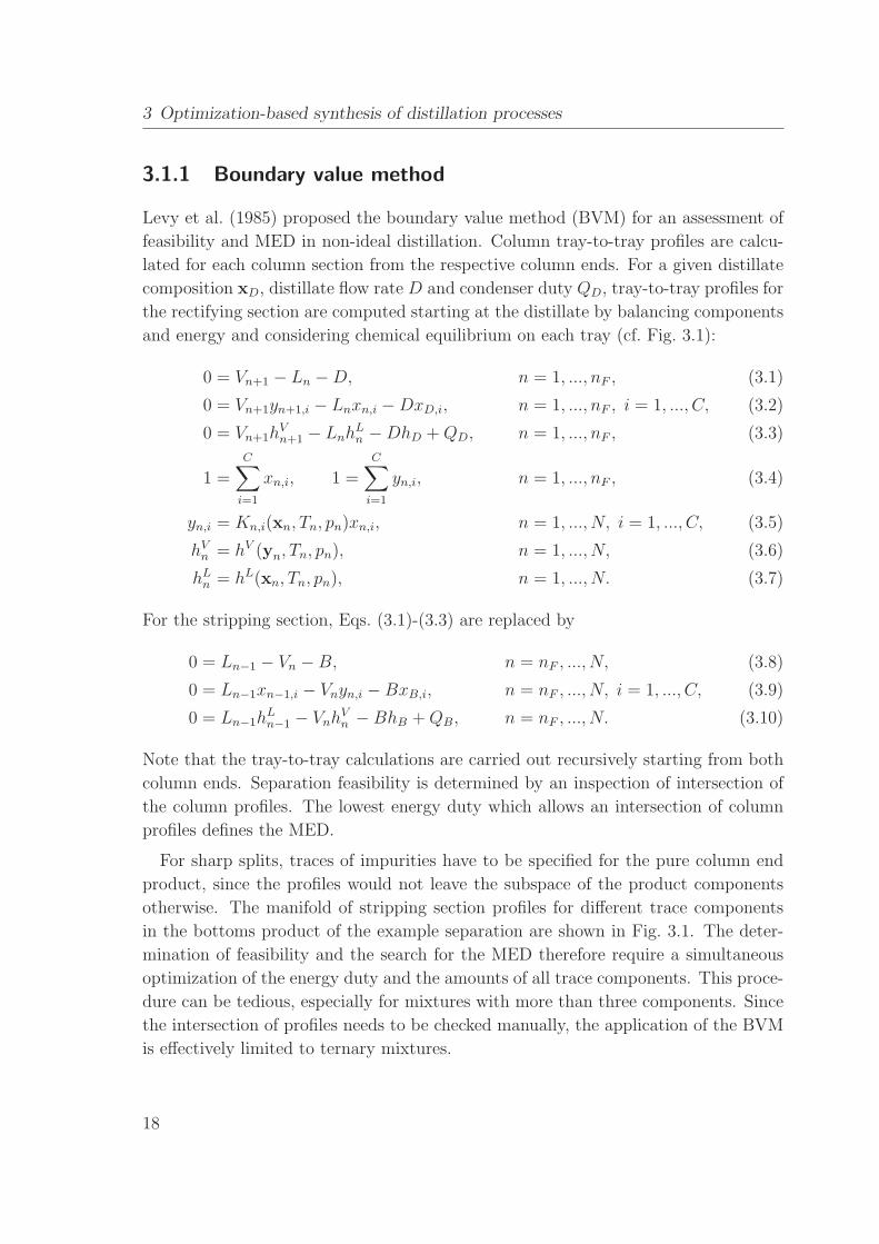
3.1.1 Boundary value method
Levy et al. (1985) proposed the boundary value method (BVM) for an assessment of
feasibility and MED in non-ideal distillation. Column tray-to-tray profiles are calcu-
lated for each column section from the respective column ends. For a given distillate
composition xD, distillate flow rate D and condenser duty QD, tray-to-tray profiles for
the rectifying section are computed starting at the distillate by balancing components
and energy and considering chemical equilibrium on each tray (cf. Fig. 3.1):
0 = Vn+1 − Ln −D, n = 1, ..., nF , (3.1)
0 = Vn+1yn+1,i − Lnxn,i −DxD,i, n = 1, ..., nF , i = 1, ..., C, (3.2)
0 = Vn+1hVn+1 − Lnh
Ln −DhD +QD, n = 1, ..., nF , (3.3)
1 =C∑i=1
xn,i, 1 =C∑i=1
yn,i, n = 1, ..., nF , (3.4)
yn,i = Kn,i(xn, Tn, pn)xn,i, n = 1, ..., N, i = 1, ..., C, (3.5)
hVn = hV (yn, Tn, pn), n = 1, ..., N, (3.6)
hLn = hL(xn, Tn, pn), n = 1, ..., N. (3.7)
For the stripping section, Eqs. (3.1)-(3.3) are replaced by
0 = Ln−1 − Vn −B, n = nF , ..., N, (3.8)
0 = Ln−1xn−1,i − Vnyn,i −BxB,i, n = nF , ..., N, i = 1, ..., C, (3.9)
0 = Ln−1hLn−1 − Vnh
Vn −BhB +QB, n = nF , ..., N. (3.10)
Note that the tray-to-tray calculations are carried out recursively starting from both
column ends. Separation feasibility is determined by an inspection of intersection of
the column profiles. The lowest energy duty which allows an intersection of column
profiles defines the MED.
For sharp splits, traces of impurities have to be specified for the pure column end
product, since the profiles would not leave the subspace of the product components
otherwise. The manifold of stripping section profiles for different trace components
in the bottoms product of the example separation are shown in Fig. 3.1. The deter-
mination of feasibility and the search for the MED therefore require a simultaneous
optimization of the energy duty and the amounts of all trace components. This proce-
dure can be tedious, especially for mixtures with more than three components. Since
the intersection of profiles needs to be checked manually, the application of the BVM
is effectively limited to ternary mixtures.
18
Page 35
3.1 Shortcut methods for non-ideal distillation
Figure 3.1: Balance envelope for the rectifying section (upper left) and composition
simplex with section profiles, pinch points, rectification bodies, and liquid
composition on the tray below the feed tray for the example separation of
the mixture of acetone, methanol, and ethanol.
Recently, Zhang and Linninger (2004) have proposed the evaluation of distillation
by a temperature collocation algorithm based on the BVM to reduce the problem size
and computational effort for the calculation of column profiles. This approach reduces
the problem size and the computational effort by replacing the conventional tray-to-
tray calculation with a bubble point temperature distance function and orthogonal
collocation on finite elements. They achieve an efficient and robust assessment of
19
Page 36
3 Optimization-based synthesis of distillation processes
feasibility and minimum reflux for the separation of multi-component ideal mixtures.
Subsequently, they have extended their approach to homogeneous azeotropic distilla-
tion and optimal column sequencing (Zhang and Linninger, 2006).
3.1.2 Pinch-based methods
In order to overcome the dependency of the BVM results on the specification of trace
components in the products, pinch-based shortcut methods have been proposed by
various authors. Pinch points describe the compositions on a distillation profile where
the driving force of the separation vanishes. Pinch point curves can be calculated for a
given product for each column section as the branches of the fixed-points of the tray-
to-tray equations if the reboiler (or condenser) duty is varied. More specifically, the
pinch equation system, derived for a balance envelope around the rectifying section
(cf. Fig. 3.1),
0 = Vp − Lp −D, p ∈ PD, (3.11)
0 = Vpyp,i − Lpxp,i −DxD,i, p ∈ PD, i = 1, ..., C, (3.12)
0 = VphVp − Lph
Lp −DhD +QD, p ∈ PD, (3.13)
1 =C∑i=1
xp,i, 1 =C∑i=1
yp,i, p = 1, ..., P, (3.14)
yp,i = Kp,i(xp, Tp, pp)xp,i, p = 1, ..., P, i = 1, ..., C, (3.15)
hVp = hV (yp, Tp, pp), p = 1, ..., P, (3.16)
hLp = hL(xp, Tp, pp), p = 1, ..., P, (3.17)
is solved for the pinch points of the rectifying section for a given energy duty QD.
Similarly, the pinch points of the stripping section can be calculated for a balance
envelope around the stripping section by replacing eqs. (3.11)-(3.13) by
0 = Lp − Vp −B, p ∈ PB, (3.18)
0 = Lpxp,i − Vpyp,i −BxB,i, p ∈ PB, i = 1, ..., C, (3.19)
0 = LphLp − Vph
Vp −BhB +QB, p ∈ PB. (3.20)
Pinch points are insensitive towards the choice of trace components. They can be
classified as stable nodes, unstable nodes, or as saddles depending on the number of
stable eigenvectors. In this thesis, we consider the nomenclature for pinch points as
introduced by Julka and Doherty (1990): the pinch points are denoted by r or s for
the rectifying and stripping section and by the number of unstable eigenvectors plus
20
Page 37
3.1 Shortcut methods for non-ideal distillation
one. The pinch points for the example separation are shown in Fig. 3.1. Here, the
stable pinch point r1 is the feed pinch. All column profiles run through this point,
regardless of the specification of trace components in the products. r2 and s2 are
the saddle pinches. The section profiles pass by these points when sufficiently pure
products are specified. Tapp, Holland, Hildebrandt and Glasser (2004) also consider
pinch points which lie outside of the composition space. By deriving so-called column
profile maps they have proposed a graphical tool to assess the feasibility of complex
column designs (Hildebrandt, Beneke, Abbas, Holland, Vrey and Glasser, 2010).
It needs to be noted that not all splits exhibit a feed pinch and saddle pinches. The
appearance of pinch points, and ultimately the applicability of pinch-based shortcut
methods, depends on the type of split. In literature, the notation of the different types
of splits is not consistent. Hence, we briefly define a notation of the splits for this
thesis and illustrate the implications of the splits on the occurrence of pinch points:
• Direct/indirect splits usually refer to separations, where a pure product, i.e. the
lightest or heaviest boiling component, is removed at the top or bottom. In this
thesis, this category also includes separations, where the lightest or heaviest
boiling azeotrope of the respective distillation region is removed at the top or at
the bottom. We will use this broader definition of direct and indirect splits here,
since these separations exhibit the same pinch point behavior: A feed pinch, i.e. a
pinch at the feed tray, usually occurs in the section where the impure product is
drawn off. Note that the impure product does not necessarily have to be located
at an edge of the composition space or at a distillation boundary.
• In intermediate splits, both column end products are not pure but are located at
the edges of the composition space or at a distillation boundary. For mixtures
with more than three components, these splits often have no feed pinch.
• Sloppy or nonsharp splits correspond to separations, where all components of
the mixture are present in both column end products and the products are not
located at a distillation boundary. For mixtures with more than three compo-
nents, these splits typically have no feed pinch. Usually, there are no saddle
pinches either. For ternary mixtures, however, sloppy (and intermediate) splits
usually exhibit a feed pinch due to the reduced dimensionality.
In the following four subsections, pinch-based shortcut methods for non-ideal dis-
tillation are reviewed.
21
Page 38
3 Optimization-based synthesis of distillation processes
3.1.2.1 Zero-volume and minimum angle criterion
For the approximation of minimum reflux conditions, the zero-volume criterion (ZVC)
introduced by Julka and Doherty (1990) and the minimum angle criterion (MAC)
suggested by Kohler, Aguirre and Blass (1991) require the feed concentration and a
subset of relevant pinch points to be on a straight line or to form a minimum angle,
respectively.
The ZVC identifies the approximate minimum reflux for the example separation
when the feed xF , the stable node pinch of the rectifying section r1, and the saddle
pinch of the stripping section s2 lie on a straight line (see Fig. 3.1). When the feed
is not a saturated liquid, the point x = (1− q)(xr1 − yr1) + xF is used instead of xF .
The ZVC for multicomponent systems uses the information of the feed, the feed pinch,
and C-2 pinch solutions in the non-pinched section. The ZVC can only be applied to
splits with a feed pinch, i.e. to direct or indirect splits, since it requires collinearity (or
coplanarity) of the selected points and the feed pinch. Moreover, Julka and Doherty
assumed constant molar overflow for the calculation of the pinch points, which is often
not valid in highly non-ideal systems.
The MAC estimates the minimum reflux in case of the separation in Fig. 3.1 by
minimizing the angle between the line connecting xF (or x) with the stable node pinch
of the rectifying section r1 and the line connecting xF (or x) with the saddle pinch of
the stripping section s2. For the indirect split of the ternary example, the MAC and
ZVC are equivalent. Contrary to the ZVC, however, the MAC considers always only
one pinch point in each section for multi-component separations. It can therefore be
inaccurate for mixtures with more than three components, where the profiles often
pass by multiple pinches in one section. Since the lines through x and the pinches do
not need to be collinear in the MAC, it can, in principle, be applied to separations
without a feed pinch. However, the MAC lacks a physical explanation in such cases.
It is therefore not astonishing that the MAC is reported to be rather inaccurate for
separations without a feed pinch (Bausa et al., 1998). An example underlining this
observation is given in Appendix B.
A physical explanation of the ZVC for separations with a feed pinch is given in
Appendix D in the work of Bausa et al. (1998). While the ZVC and the MAC are
computationally efficient due to the lack of tray-to-tray calculations, both criteria
suffer from the drawback that the selection of the relevant pinch points can be rather
complicated and time-consuming, particularly for mixtures with more than three com-
ponents.
22
Page 39
3.1 Shortcut methods for non-ideal distillation
3.1.2.2 Eigenvalue criterion
The eigenvalue criterion (EC) introduced by Pollmann, Glanz and Blass (1994) can
be considered a pinch-based BVM. Instead of calculating profiles starting from both
column ends, the tray-to-tray computation is started from points close to the saddle
pinches in the direction of the unstable eigenvectors. The minimum reflux condition
is achieved at the smallest reflux ratio which makes an intersection of the profiles
possible. Again, the selection of the relevant subset of active pinch points is not
trivial. For multicomponent mixtures with more than one unstable eigenvector per
pinch point, multi-dimensional manifolds of column profiles have to be checked for
intersection, which can be a costly procedure, the more so as the automation of the
check for intersection remains difficult.
3.1.2.3 Rectification body method
Bausa et al. (1998) introduced the rectification body method (RBM) as an algo-
rithmically accessible procedure to estimate the MED in multicomponent azeotropic
distillation. Here, all pinch point solutions of the candidate separation are computed
reliably from a robust implementation of the pinch equation system (Bausa, 2001).
Then, possible paths along pinch points with an increasing number of stable eigen-
vectors are generated and checked for thermodynamic consistency by excluding paths
where the entropy production does not increase strictly monotonously. Convex rec-
tification bodies which approximately describe the manifold of all profiles are then
constructed for each section by linearly connecting the pinch points contained in the
paths (cf. Fig. 3.1). The minimum energy duty is calculated by iteratively identifying
the lowest reboiler duty that results in an intersection of a set of bodies. Since all
pinch points are used, no a-priori selection of relevant pinch solutions is required. The
check for intersection of the convex rectification bodies can be performed very effi-
ciently. Therefore, the method can be automated and applied to mixtures with any
number of components. Harwardt et al. (2008) have calculated the MED by means of
the RBM for separations with more than 10 components in about 10 CPU seconds on
a standard PC. In fact, these authors show that the computational efficiency of the
RBM facilitates a rapid optimization of large column sequence superstructures for the
separation of zeotropic multicomponent mixtures of up to 8 components. The RBM
has been extended to handle complex columns (Von Watzdorf, Bausa and Marquardt,
1999; Bruggemann, 2005) and extractive columns Bruggemann and Marquardt (2004).
It should also be noted that the RBM is applicable to direct, indirect, as well as inter-
mediate splits, which often have no pinch at the feed tray when the mixture contains
23
Page 40
3 Optimization-based synthesis of distillation processes
more than three components. In this case, the rectification bodies for the rectifying
section and the stripping section intersect at the edges (see Bausa et al. (1998) or
Appendix B). In case of a tangent pinch, three pinch points can be determined on
one pinch point curve. Hence, only the first pinch on each pinch point curve is used.
When the energy is increased such that the tangent pinch disappears, the rectifica-
tion bodies overlap at MED. Sloppy splits, however, often exhibit no saddle pinches
such that the RBM with linear rectification bodies returns an inaccurate estimation
of MED for these splits.
Furthermore, the RBM, only returns a good estimate of MED in those cases where
the profiles between the pinch points are not strongly curved. Still, most homoge-
neous mixtures exhibit only a weak nonlinear behavior such that the linearization
of the rectification bodies is a good assumption. Heterogeneous mixtures, however,
often exhibit strongly curved column profiles in and around the miscibility gap, which
complicate the application of the RBM (Bausa (2001), see also Section 4.3.2).
3.1.2.4 Petlyuk’s methodology
Petlyuk (2004) proposed a comprehensive methodology for the optimal design of mul-
ticomponent azeotropic distillation. In his works, design procedures are developed for
infinite reflux, minimum reflux and reversible distillation conditions and for all kinds
of splits. Petlyuk uses the information of the separation pinch points but derives their
location by calculating tray-to-tray profiles with constant molar overflow instead of
directly solving the pinch equation system.
In a first approximate design step, the methodology for the calculation of the mini-
mum reflux of a direct or indirect split requires a subset of pinches in the non-pinched
section and the tray above or below the feed tray, respectively, to be on a straight
line. The liquid composition on the tray above or below the feed tray is determined
by a simplified mass balance around the feed tray assuming constant molar overflow.
In the example in Fig. 3.1, the tray below the feed tray is brought to intersection with
the line connecting the pinch points s1 and s2 of the non-pinched stripping section.
More tedious iterative procedures are required for intermediate and non-sharp splits
without a feed pinch.
Petlyuk’s methodology can be applied to a wide variety of separations. However,
the approximate design step suffers from low accuracy for highly non-ideal mixtures
due to the assumption of constant molar overflow and the linearization of the profiles
between the pinch points. In addition, the selection of the relevant pinch points is not
trivial for mixtures with more than three components. Petlyuk suggests to refine the
24
Page 41
3.1 Shortcut methods for non-ideal distillation
prediction of minimum reflux in a more rigorous second design step, where attainable
regions are derived with the help of iterative tray-to-tray profile calculations. As a
drawback, this design step is computationally expensive.
3.1.3 Shortest stripping line method
Lucia, Amale and Taylor (2008) proposed the shortest stripping line method (SSLM)
to find minimum energy designs in multicomponent azeotropic distillation. The au-
thors show that the shortest stripping line which produces a feasible separation,
i.e. where the product purities are reached by the section profiles, marks the MED.
When the feed pinch occurs in the stripping section, the SSLM suggests the calcula-
tion of a large number of stripping section trays, e.g. 300, starting from the bottoms
product such that the feed pinch is reached. Then, the rectifying profile is calculated
upwards from the feed pinch. When the feed pinch occurs in the rectifying section,
a search for the stripping profile passing through the feed is started. The rectifying
profile is then calculated upwards from the intersection of the stripping profile with
the pinch line of the feed pinch in the rectifying section. This procedure involves the
solution of a MINLP problem to find the required intersections. In both cases, the
MED is found by a minimization of a distance function along the discrete stripping
trajectory while the product purities must be reached.
While the SSLM is based on the constant molar overflow assumption, it has been
successfully applied to homogeneous zeotropic and azeotropic mixtures of up to six
components and to multi-unit processes (Lucia et al., 2008). The concept has also
been extended to non-pinched minimum energy designs, which can be identified by
the solution of a subsequent MINLP problem (Amale and Lucia, 2008). While the
feasibility check can easily be automated for direct and indirect splits, automation is
more challenging for intermediate or sloppy splits. For these splits, the unstable nodes
are not located at the section end. As a consequence, the profile does not terminate
at the end product for a large number of trays, but passes by or continues past the
end product. Hence, the entire section profile needs to be checked for intersection
with the end product, which is much more difficult algorithmically.
Due to the large number of tray-to-tray calculations, the SSLM demands a higher
computational effort particularly for the evaluation of large processes, where the oc-
currence of recycles requires an optimization of the process operating point.
25
Page 42
3 Optimization-based synthesis of distillation processes
3.2 Process evaluation with shortcut methods
A meaningful assessment of separation cost and comparison of alternatives can only be
accomplished at the respective optimal operating points of the considered flowsheets.
For a numerical optimization of the process operating point, a fully algorithmic and
computationally efficient shortcut method is required. For most homogeneous mix-
tures, the RBM (cf. Section 3.1.2.3) offers both sufficient accuracy and computational
efficiency such that the method is suited for use in process optimization. The RBM,
however, can be inaccurate for heteroazeotropic, highly non-ideal, or reactive distil-
lation. For these applications, a novel shortcut method based on the RBM will be
introduced in Sections 4.5 and 7.2.
When the RBM or a related pinch-based shortcut method is used for the numerical
optimization of process recycles, an algorithmic formulation of a feasibility criterion is
necessary in addition. This feasibility test has to be algebraically accessible and needs
to provide information on the distance of a selected point to a distillation boundary.
Both of these criteria are met by the so called pinch distillation boundary (PDB),
which marks the distillation boundary at minimum reflux (Davydian, Malone and
Doherty, 1997; Bruggemann and Marquardt, 2011a). It is therefore very well suited
to be used in conjunction with the RBM, since here the columns are also assumed to
operate at minimum reflux. In contrast, the simple distillation boundary reflects the
distillation boundary at infinite reflux.
The mathematical formulation of the PDB is based on the (pitchfork) bifurcation
phenomena of the pinch lines, which can be detected using a test function and con-
tinued by a homotopy continuation method. An algebraic criterion then checks the
distance of the column products from the distillation boundary. Further mathematical
details are given in the work of Bruggemann and Marquardt (2011a). It needs to be
noted that the feasibility check is general and can be applied to arbitrary azeotropic
mixtures. It can be used without limitations regarding the number of components or
certain types of splits since it does not require graphical inspection.
Supplemented by the RBM for the calculation of the MED and an objective func-
tion to minimize the total process energy demand, the PDB can then be used for
the numerical optimization of process operating points. Several case studies can be
found in the works of Bruggemann (2005), Bruggemann and Marquardt (2011b) and
Kossack, Refinius, Bruggemann and Marquardt (2007). However, it will be shown
in Section 3.4.1 that the repeated call of the PDB homotopy continuation in every
iteration step of such an optimization procedure can significantly slow down the so-
lution times, even to an extent that the process optimization with shortcut methods
26
Page 43
3.3 Rigorous optimization
requires longer solution times than a rigorous process optimization. A speedup of the
PDB-based feasibility check by a-priori calculation and approximation of the PDB is
a topic of current research (see also Section 8.1.2). It has therefore not been available
for application in the case studies of this thesis. Hence, a simplified approach, which
requires no calculation of PDBs, is proposed in Section 4.5.2 and used for the process
optimization within the shortcut evaluation steps in Chapters 4 and 5.
3.3 Rigorous optimization
The evaluation of a distillation process with the RBM in combination with the PDB
as portrayed in Section 3.2 serves as a good approximation to inspect feasibility and
compare different process flowsheets by means of minimum energy demand. However,
no conclusions can be made regarding the optimal tray numbers, the optimal loca-
tion of feeds and side streams, product purities, and capital costs. This information
can be gained by a rigorous optimization of the process with an economic objective
function, where the columns are represented by tray-to-tray models. The resulting
optimization problem is of discrete-continuous nature due to the discrete decisions
concerning the tray numbers and stream locations, and the continuous values of en-
ergy duties, flow rates, and compositions. While the rigorous optimization of a single
distillation column is already non-trivial due to the discrete-continuous nature and the
nonlinearity and non-convexity of the underlying thermodynamics, the optimization
of distillation processes with recycles poses an even more difficult challenge. Large
and complex superstructures have to be defined and solved if all possible splits and
column configurations are to be considered (Bauer and Stichlmair, 1998). Given the
large scale and the complexity, it becomes clear that these optimization problems are
computationally expensive and that the quality of the final solution strongly depends
on the specified initial values (Dunnebier and Pantelides, 1999).
As a consequence of these difficulties, the examples of rigorous optimization of distil-
lation processes in the literature are confined to different assumptions, simplifications
or limitations. Viswanathan and Grossmann (1990) were the first to publish a gen-
eral MINLP formulation for tray optimization of single columns. They apply this
formulation to an ideal binary mixture and later to azeotropic mixtures (Viswana-
than and Grossmann, 1993). Dunnebier and Pantelides (1999) have extended this
method to include multi-column systems and an economic objective function but also
only consider ideal separations. Bauer and Stichlmair (1998) have developed a rigor-
ous optimization procedure for azeotropic separations which first generates separation
27
Page 44
3 Optimization-based synthesis of distillation processes
splits based on preferred separations and complements this sequence generation with
a MINLP tray optimization. However, they only look at ternary mixtures and report
long computational times. In a series of papers, Barttfeld and Aguirre (2002, 2003)
develop a method for the optimal synthesis of ternary zeotropic distillation processes
based on the concept of reversible separation. They solve the MINLP problem effi-
ciently due to a preprocessing phase but cannot handle sharp splits, which are not
allowed in reversible separation schemes.
The tray optimization formulations in the works mentioned above all suffer from the
numerical difficulties inherent to large-scale MINLP optimization: lack of robustness,
long computational times and sensitivity to local optima. As a consequence, efforts
have been made to apply alternative optimization approaches to the column optimiza-
tion problem. Yeomans and Grossmann (2000) formulate general disjunctive program-
ming (GDP) representations for the economic optimization of distillation columns for
reversible separations and Barttfeld, Aguirre and Grossmann (2003) compare its so-
lution properties to MINLP formulations. They claim that the GDP representation
increases the robustness in the solution as non-existent trays are not included in the
subproblems. Still, the GDP has to be reformulated and solved as a MINLP since the
development of logical solvers which are capable of handling logical constraints has not
yet progressed sufficiently. The numerical results of their case studies for non-sharp
separation of ternary mixtures in a single column suggests that the GDP formulation
requires less solution time but is more sensitive towards local optima than MINLP
formulations. Farkas, Czuczai, Rev and Lelkes (2008) reformulate GDP representa-
tions of complex distillation systems as MINLP problems and apply a modified outer
approximation algorithm which provides good initial values for the NLP subproblems.
They optimize a complex distillation process for an azeotropic quaternary example
but still report solution times larger than 1 h. In general, the GDP representations
modeling the column size by existing or non-existing (i.e. by-passed) trays cannot
benefit from the tight relaxations of the MINLP formulations, where the column size
is modeled by a variable reflux/reboil location, variable condenser/reboiler location
or variable product stream location.
Various authors, including Barkmann, Sand and Engell (2008), solve rigorous col-
umn optimization problems by genetic algorithms. While this approach benefits from
good robustness, the computational times prove to be significantly longer than for
gradient-based optimization.
Linninger and his co-workers extend their temperature collocation algorithm (cf. Sec-
tion 3.1.1) to the rigorous design of complex column networks in a series of papers
(Kim, Ruiz and Linninger, 2010; Kim and Linninger, 2010; Ruiz, Kim, Moes and Lin-
28
Page 45
3.3 Rigorous optimization
ninger, 2011). In their case studies, the authors include multicomponent and non-ideal
mixtures but do not study processes with recycles. In addition, economic objective
functions are not considered.
Recently, continuous reformulations of MINLP problems which can be solved with
robust NLP solvers have gained increased attention due to the remaining drawbacks
of discrete optimization. Lang and Biegler (2002) proposed a column optimization
formulation, where the discrete decisions, i.e. number of trays and feed tray loca-
tion, are modeled by continuous variables. The authors place the continuous decision
variables on bell-shaped curves with the help of a differentiable distribution function
in order to locate optimal regions for the feed and the reflux/reboil streams. The
optimization is then carried out in a series of continuous NLP problems where the
variance of the bell-shaped distribution function is gradually reduced. While this ap-
proach is very promising, some of the following simplifications apply for each of their
published case studies: linear objective functions, non-sharp splits, fixed feeds, single
columns or ideal mixtures. In addition, they only obtain a narrow distribution of
the decision variables instead of an integer solution. Neves, Silva and Oliveira (2005)
presented an alternative strategy for the continuous optimization of tray optimization
problems, where they replace the differentiable distribution functions by numerically
easier to handle nonlinear constraints that force the continuous decision variables to
integer values. Like Lang and Biegler (2002), they solve the continuous problem in
a sequence while reducing relaxation parameters. The robustness is increased due to
the continuous approach, a pre-processing phase based on shortcuts and the addition
of slack variables. However, the published case studies are confined to the tray opti-
mization of either single columns or distillation processes with a fixed number of trays.
Kraemer, Kossack and Marquardt (2009) have studied the rigorous optimization
of large-scale and complex distillation processes for the separation of homogeneous
azeotropic mixtures. In their work, substantial progress has been made towards the
robust and efficient solution of these optimization problems through measures on two
levels:
• Initialization by shortcut evaluation. The integration of the rigorous opti-
mization into the process synthesis framework (cf. Chapter 2.6) allows a reduc-
tion of the process superstructure a priori. Thus, elementary design decisions
like the selection of splits, the flowsheet structure, the column pressures or the
choice of entrainer are already made before the rigorous optimization is set up.
In addition, the shortcut evaluation provides excellent initial values and bounds
for the rigorous optimization (see Section 3.3.3).
29
Page 46
3 Optimization-based synthesis of distillation processes
• Continuous reformulation. The resulting MINLP problems are reformulated
as purely continuous problems, which are solved as a series of a few easier to
solve NLP problems with successively tightened bounds as presented in Sections
3.3.2 and 3.3.4. These rigorous tray optimization problems are solved with out-
standing efficiency and robustness by formulating a particular tight continuous
representation. Because of the tight optimization formulation, the local optima
are located in a narrow range in the continuous space and, thus, special nonlin-
ear constraints to force integer decisions can be handled robustly. We will see
that continuously reformulated tray optimization problems can be solved signif-
icantly faster than the corresponding MINLP problems. The reduction of the
computational time is of great benefit when varying specifications for product
purities, pressures, feed compositions or cost parameters necessitate numerous
design evaluations.
3.3.1 MINLP column model
In general, a tray-to-tray optimization problem can be formulated as a GDP, where
the column size is modeled by existing or non-existing (i.e. by-passed) trays, or as
a MINLP, where the column size is modeled by variable column ends. Contrary
to the GDP column representations, MINLP column formulations exhibit very tight
relaxations and are therefore better suited for continuous reformulation. Different
column superstructures for the MINLP tray optimization can be found in the liter-
ature (Bauer and Stichlmair, 1998; Barttfeld et al., 2003). MINLP formulations for
three different superstructure variants as illustrated in Fig. 3.2 were reformulated as
continuous problems by Kraemer, Kossack and Marquardt (2009) and compared for
robustness, reliability and efficiency.
Superstructure variant (a) determines the number of column trays by a variable
reflux scheme as proposed by Viswanathan and Grossmann (1993). The top tray
models the condenser and as the reflux is moved to lower trays, the trays between the
reflux location and the top tray dry up, i.e. the liquid overflow disappears for these
trays. Note that the introduction of smoothing functions, which Lang and Biegler
(2002) formulate to handle the loss of phases on dried-up plates becomes redundant
since pressure drops and heat losses are neglected in this thesis. Superstructure variant
(b) has the condenser heat exchange as variable to control the tray number. Heat is
exchanged on the top tray in any case when the distillate product leaves the column
as boiling liquid. Comparable to variant (a), the trays above the last existing tray
dry up. Again, no smoothing function for dried up trays is required when the column
30
Page 47
3.3 Rigorous optimization
Figure 3.2: Alternative superstructures for the tray optimization of distillation
columns. The top ends of the columns are variable in this case.
B,xN
D,x1
QD
QB
bF,1,nF1,zF,1 bS,V,nSV,yn
bS,L,nSL,xnbF,2,nF2,zF,2
bR,B,nRB,yN
bR,D,nRD,x1
Figure 3.3: Tray optimization superstructure used in this thesis. Both column ends
are variable. Multiple feeds and vaporous as well as liquid side draws are
considered.
31
Page 48
3 Optimization-based synthesis of distillation processes
pressure drop and heat losses are neglected. Superstructure variant (c) models the
size of the column by a variable distillate product stream and condenser heat location.
The trays above the product draw are still calculated but are of no relevance.
Superstructure variant (a) offered the best results as far as solution times and quality
of the local optima are concerned. Hence, only superstructure variant (a) is applied
in the case studies in this thesis. While all column configurations can be modeled
by variable feed and either variable reflux or variable reboil positions, it needs to
be noted that the feed and both the reflux and the reboil positions are variable in
the superstructure applied in this thesis. This superstructure, which is depicted in
Fig. 3.3, proved to yield even better local optimal solutions. Multiple feeds and side
draws are also considered in the superstructure in Fig. 3.3.
tray n
Ln-1,xn-1 Vn,yn
Ln,xn Vn+1,yn+1
bF,k,nFk,zk
bRD,nRD,x1
bSV,nSV,yn
bSL,nSL,xn
bRB,nRB,xN
Figure 3.4: Equilibrium tray with streams for the superstructure depicted in Fig. 3.3.
The rigorous column optimization model for a single column and the superstructure
depicted in Fig. 3.3 is listed as follows:
min TAC = Cop · ta + fc · Ccap, (3.21)
s.t.
0 =K∑k=1
bF,k,nFkzk,i + Ln−1xn−1,i + Vn+1yn+1,i − Lnxn,i − Vnyn,i − bSL,nSLxn,i
− bSV ,nSV yn,i + bRD,nRDx1,i + bRB ,nRByN,i, n = 2, ..., N − 1, i = 1, ..., C, (3.22)
0 =K∑k=1
bF,k,nFkhF,k + Ln−1hLn−1 + Vn+1h
Vn+1 − Lnh
Ln − Vnh
Vn − bSL,nS
LhLn
− bSV ,nSV hVn + bRD,nRDh
L1 + bRB ,nRBh
VN , n = 2, ..., N − 1, (3.23)
32
Page 49
3.3 Rigorous optimization
0 =
K∑k=1
bF,k,nFkzk,i + Vn+1yn+1,i −Dxn,i −RDxn,i, n = 1, i = 1, ..., C, (3.24)
0 =
K∑k=1
bF,k,nFkhF,k + Vn+1hVn+1 −DhLn −RDh
Ln +QD, n = 1, (3.25)
0 =K∑k=1
bF,k,nFkzk,i + Ln−1xn−1,i −Bxn,i −RByn,i, n = N, i = 1, ..., C, (3.26)
0 =K∑k=1
bF,k,nFkhF,k + Ln−1hLn−1 −BhLn −RBh
Vn +QB, n = N, (3.27)
0 = L1, (3.28)
0 = VN , (3.29)
C∑i=1
xn,i = 1,
C∑i=1
yn,i = 1, n = 1, ..., N, (3.30)
yn,i = Kn,i(xn,yn, Tn, pn)xn,i, n = N, i = 1, ..., C, (3.31)
hVn = hV (yn, Tn, pn), n = 1, ..., N, (3.32)
hLn = hL(xn, Tn, pn), n = 1, ..., N. (3.33)
N∑n=1
bF,k,n = 1,N∑
n=1
bSL,n = 1,N∑
n=1
bSV ,n = 1,
N∑n=1
bRD,n = 1,
N∑n=1
bRB ,n = 1, k = 1, ...,K, (3.34)
N∑n
bRD,n + bF,k,n ≤ 1,
n∑1
bRB ,n + bF,k,n ≤ 1, n = 1, ..., N, k = 1, ...,K, (3.35)
xn,i ≥ xD,purity, n = 1, i = light component, (3.36)
xn,i ≤ xB,purity, n = N, i = light component, (3.37)
Ncol = N −N∑
n=1
N∑n=1
bRD,n −N∑
n=1
N∑n=1
bRB ,n, (3.38)
Cop = f(QB, QD), (3.39)
Ccap = f(Ncol, Dcol, Areb, Acon). (3.40)
The column model is based on the MESH equations, which specify tray-to-tray
mass and energy balances and assume VLE conditions on every column tray. The
streams to and from a tray are visualized in Fig. 3.4. The symbol b (with particular
33
Page 50
3 Optimization-based synthesis of distillation processes
indices) denotes binary variables to indicate whether the stream is present or not.
Component mass balances and energy balances are given in eqs. (3.22) and (3.23)
for each tray except the topmost and the lowest trays, which represent the condenser
and the reboiler, respectively. For these, component mass and energy balances are
given in eqs. (3.24)-(3.29). Eq. (3.30) refers to the closure relations for the liquid
and vapor compositions on each tray. The vapor-liquid equilibrium and the vapor
and liquid enthalpies are described by eqs. (3.31)-(3.33). For the K-values, the liquid
activity coefficients γ are calculated by means of a common gE model (e.g. Wilson,
UNIQUAC, NRTL, UNIFAC). The pure component vapor pressure is determined by
the extended Antoine equation whereas vapor phase fugacities coefficients are set to
1 for the mixtures in this thesis. DIPPR equations are employed for the calculation
of the enthalpies. It needs to be noted that column pressure drop is neglected in this
thesis. The addition of slack variables to the balances and the equilibrium condition
for better convergence properties as in the work by Neves et al. (2005) can be neglected
due to the sound initialization of the optimization problem (see Section 3.3.3). Closure
relations apply for the binary variables modeling the column feed locations, bF,k,n, side
draw locations, bSL,n, bSV ,n, and the reflux and reboil locations bRD,n, bRB ,n (eq. (3.34)).
Eq. (3.35) guarantees that the column feeds are located between the trays where the
reflux and reboil is introduced. Purity constraints are added for the distillate and
bottom products in eqs. (3.36) and (3.37) to ensure product quality. A sharp split
for the light component is specified here. Sharp splits for the heavy component or
intermediate splits can be specified analogously.
The objective function reflects the total annualized column cost composed of oper-
ating cost (cost for cooling and heating, eq. (3.39)) and capital cost (investment for
column shell, trays and heat exchangers, eq. (3.40)). The capital cost, which depends
on the tray number, the column diameter and the areas of the heat exchangers, is
calculated from nonlinear cost models given by Douglas (1988) and updated by the
M&S index. The capital charge factor fc accounts for the depreciation time including
interest. The number of trays are calculated by eq. (3.38). The remaining sizing and
costing functions for the equipment considered in this thesis are given in Appendix C.
In order to optimize a whole distillation process of several columns, the single col-
umn models are connected by flowsheet streams with variable flow rates and compo-
sitions. Furthermore, the purity constraints on column end products which constitute
flowsheet intermediate and recycle streams are removed. The objective function is
then specified as the minimization of the cumulated annualized operating and capital
costs of all columns in the process.
34
Page 51
3.3 Rigorous optimization
3.3.2 Continuous reformulation of MINLP problems
Optimization problems in engineering are often of discrete-continuous nature and usu-
ally nonlinear or even nonconvex. In the field of chemical engineering for example,
typical examples include the synthesis of reactor or heat exchanger networks, and unit
or flowsheet structure optimization. The discrete variables in these examples usually
stem from the structural decisions whereas typical continuous variables are composi-
tions or energies, etc.. In addition, thermodynamics, reaction kinetics and economic
objective functions add strong nonlinearities. Due to the combined computational
challenges from both the discrete nature and the nonlinearity, these problems are par-
ticularly hard to solve. Specifically, the solution performance often suffers from the
lack of robust solution algorithms, the necessity of a proper initialization with good
starting points and long computational times. In the light of these challenges it is
comprehensible that only few applications of large-scale discrete-continuous nonlinear
optimization have been realized in industry.
Discrete-continuous nonlinear optimization problems are usually formulated as
MINLP problems. Lastusilta, Bussieck and Westerlund (2009) give a comparison
of the performances of different MINLP solvers, including recent developments such
as CoinBonmin (Bonami, Biegler, Conn, Cornuejols, Grossmann, Laird, Lee, Lodi,
Margot, Sawaya and Wachter (2008)). In recent years, global MINLP solvers for non-
convex problems have been developed and successfully applied to problems of small to
medium scale (BARON, Tawarmalani and Sahinidis (2005)). The high computational
effort however still prohibits the use of these solvers for large-scale problems. Local
optimization algorithms for MINLP problems are usually based on decomposition
methods or tree-search algorithms. Decomposition methods, e.g. outer approxima-
tion (Viswanathan and Grossmann, 1990), rely on an iteration between overestimating
nonlinear programming (NLP) subproblems and underestimating mixed-integer lin-
ear programming (MILP) subproblems. Tree search algorithms like branch & bound
(Gupta and Ravindran, 1985) perform a search in the space of the NLP subproblems
with intelligent node selection and elimination. While these local MINLP solvers have
been applied to large-scale problems, the solution robustness, reliability, and efficiency
still remain challenging.
In recent years, discrete-continuous nonlinear optimization problems have also been
reformulated as purely continuous optimization problems. The resulting nonconvex
NLP problems can then locally be solved with NLP solvers. Continuous reformulation
was first successfully applied to optimization problems in the form of mathematical
programs with equilibrium constraints (MPEC) (Fletcher and Leyffer, 2004). Here,
35
Page 52
3 Optimization-based synthesis of distillation processes
the equilibrium conditions in the MPEC problems are replaced by nonconvex con-
tinuous formulations enforcing the discrete decisions. More recently, general MINLP
problems have also been reformulated as purely continuous problems by replacing
the discrete variable set with continuous variables (Stein, Oldenburg and Marquardt,
2004; Kraemer, Kossack and Marquardt, 2007). Comparable to MPECs, the discrete
decisions are then reached by adding special nonconvex constraints.
Certain discrete-continuous problems can be formulated as MPEC problems where
discrete decisions are represented by equilibrium conditions. The equilibrium condi-
tion implies that either a constraint is enforced or a decision variable is at its bounds.
MPEC problems are often reformulated as NLP problems and solved by NLP solvers.
One way to reformulate the equilibrium constraint (EC) is to introduce a penalty
function in the objective which penalizes non-discrete solutions. The EC can also be
modeled by complementarity constraints in the form of binary multiplications. Vari-
ous authors suggest to use NCP-functions for the formulation of the EC (Fletcher and
Leyffer, 2004). However, all these reformulation strategies share one drawback: They
violate the linear independence constraint qualification (LICQ) and the Mangasarian-
Fromovitz constraint qualification (MFCQ) (Scheel and Scholtes, 2000). It was there-
fore proposed to relax the reformulations by adding a relaxation parameter µ to the
EC. The problem is then solved in a series of successive NLPs as the relaxation param-
eter µ is reduced to zero. Stein et al. (2004) transferred the continuous reformulation
approach to MINLP problems, which were derived from general disjunctive programs
via big-M constraints. The Fischer-Burmeister (FB) NCP-function (Jiang and Ralph,
2000) was employed to enforce the discrete decisions. Later, Kraemer et al. (2007)
proposed an extension of the continuous reformulation approach to include general
formulations of MINLP problems with binary variables, which are given by
minx,b
f(x,b), (3.41)
s.t. g(x,b) ≤ 0,
h(x,b) = 0,
x ∈ ℜn, b ∈ {0, 1}m.
For the continuous reformulation, the binary variables b ∈ {0, 1} were replaced by
continuous variables c ∈ [0, 1]. FB NCP-functions were used to force these continuous
variables to take on binary values:
1 ≤√ci2 + (1− ci)2 + µ, i ∈ [1,m]. (3.42)
Note that the FB NCP-function was relaxed by the relaxation parameter µ which was
36
Page 53
3.3 Rigorous optimization
reduced to zero in a series of successive NLPs. A discrete solution is returned by the
last NLP where µ = 0.
The continuous reformulation of MPECs and solution as NLPs has been applied to
large MPEC problem libraries with good results (Fletcher and Leyffer, 2004; Baum-
rucker, Renfro and Biegler, 2008). Until the work of Kraemer and Marquardt (2010),
however, continuous reformulation strategies have not been applied to MINLP prob-
lem libraries. Hence, Kraemer and Marquardt studied the performance of continuous
reformulation of MINLP problems empirically by means of a large MINLP test prob-
lem library.
In their work, 98 representative test problems of the MINLP library MINLPLib
were reformulated with the help of FB NCP-functions and solved in a series of NLP
steps while a relaxation parameter is reduced. The solution properties are compared
to the MINLP solution with branch & bound and outer approximation solvers. Since
a large portion of the reformulated problems yield local optima of poor quality or
cannot even be solved to a discrete solution, a reinitialization and a post-processing
procedure were proposed. Extended with these procedures, the reformulation achieved
a comparable performance to the MINLP solvers SBB and DICOPT for the 98 test
problems. Details of this study and a comprehensive analysis of the results is given
in Appendix A.
3.3.2.1 Continuous reformulation of MINLP column model
The MINLP tray optimization formulation proposed in Section 3.3.1 exhibits very
tight relaxations. When the MINLP problem is relaxed, the feeds, reflux, reboil, and
side streams are usually introduced on a few adjacent trays in the optimal relaxed
solution. It is important to note that similar relaxation characteristics apply to the
cascade optimization problems for extraction columns and crystallization cascades in
Sections 5.2.1, 6.1 and 6.2. Because of this property, the MINLP tray optimization
problems in this thesis are perfectly suited for continuous reformulation, where the
tight relaxations can be ideally exploited. In order to gain a purely continuous formu-
lation, the binary variables modeling the reflux and reboil location, i.e. the number
of column trays in the MINLP model in Section 3.3.1, bRD,n and bRB ,n, and the feed
and side stream locations, bF,k,n, bSL,n, bSV,n, are replaced by the respective continuous
decision variables cRD,n, cRB ,n, cF,k,n, cSL,n and cSV ,n.
Discrete decisions are then reached by the addition of nonlinear constraints in the
37
Page 54
3 Optimization-based synthesis of distillation processes
form of the Fischer-Burmeister function:
1 ≤√cm,n
2 +(1− cm,n
)2+ µ, m ∈ {Fk, RD, RB, S
L, SV }, n = 1, ..., N, (3.43)
similar to eq. (3.42), which force the continuous decision variables cm,n to integer
values when µ = 0. Given that∑
n cm,n = 1 and cm,n ≥ 0, optimal discrete trays
are determined for the feeds, reflux, reboil, and side stream locations. The relaxation
parameter µ is added to the right hand side of eq. (3.43) in order to improve the
numerical properties of the Fischer-Burmeister function. Typically, µ is reduced from
µ = 0.5 to µ = 0.2 and µ = 0 in a series of a few solution steps until an integer
solution is reached when µ = 0 (see Section 3.3.4).
As far as the feed distribution is concerned, Viswanathan and Grossmann (1993)
already observed that a single column feed is optimally distributed when it is intro-
duced on a single column tray. Kossack et al. (2006) has interpreted this property
as a maximization of effective trays in each column section: the largest sections are
obtained when the impure feed is introduced on a single tray and thus placed farthest
away from both column ends. Kraemer, Kossack and Marquardt (2009) have ob-
served, however, that multiple feed columns do not typically have discrete feed trays
in the optimal solution of the relaxed problem. The costs for a two feed column, for
example, are usually minimal when one feed is introduced on a single tray while the
other feed is distributed among several trays. Here, Fischer-Burmeister constraints
(eq. (3.43)) are added to enforce discrete decisions.
3.3.3 Initialization
The complex large-scale nonlinear tray optimization problem of Section 3.3.1 requires
a sound initialization to allow for a robust, reliable and efficient solution. Different
initialization concepts are known from the literature, which typically suffer from the
drawback that a priori knowledge about the distillation process is required to specify
initial values and bounds. Various authors (e.g. Barttfeld et al. (2003); Neves et al.
(2005); Kossack et al. (2006)) have reported, however, that a favorable initialization of
the column optimization improves both the robustness and the probability to identify
good local optima. In order to identify appropriate initial values, different proposals
for pre-processing phases have been published. Fletcher and Morton (2000) generate
initial values by studying the limiting column condition at infinite reflux. Energy
efficient columns, however, operate close to minimum rather than infinite reflux con-
ditions. Barttfeld and Aguirre (2002, 2003); Barttfeld et al. (2003) use the theory of
reversible distillation of Kohler et al. (1991) to identify the energy-efficient ”preferred
38
Page 55
3.3 Rigorous optimization
separation” and to use it for initialization. As a drawback, this concept usually leads
to non-sharp splits for azeotropic mixtures.
In this thesis (see also Kossack et al. (2006)), the integration of the rigorous optimi-
zation in the synthesis framework introduced in Chapter 2.6 offers excellent prospects
for initialization as initial values and bounds can be directly retrieved from the preced-
ing shortcut evaluation with the RBM. The initialization procedure not only provides
a feasible starting point for the rigorous optimization but indeed an excellent one
due to the proximity of the minimum reflux condition to the real column operating
condition.
Figure 3.5: Steps of the initialization procedure. For illustration purposes, the rec-
tification bodies and flowsheets at the respective initialization step of an
extractive distillation process are included.
The initialization procedure for the rigorous optimization of distillation processes
39
Page 56
3 Optimization-based synthesis of distillation processes
is carried out in several steps as illustrated in Fig. 3.5. Kraemer, Kossack and Mar-
quardt (2009) state that a stepwise initialization of the optimization problem with
gradually refined models helps both robustness as well as efficiency, although more
simulations and optimization runs have to be carried out. For the initialization, the
process is therefore at first disaggregated into single columns which are initialized sep-
arately with the column feed and product streams being fixed at the optimal values
from the preceding shortcut evaluation. Initial linear column composition and tem-
perature profiles are derived for every column from the linear piece-wise combination
of the pinch points calculated by the RBM in the shortcut step, providing very good
approximations of the actual column profiles. These linear profiles then serve as ini-
tialization for a rigorous column simulation for which the tray number is fixed at a
user-specified maximum value and energy balances are neglected in order to facilitate
easy convergence of this initializing column model. Note that the feed tray location
is set free to prevent an infeasible specification by the user. In the next step, energy
balances are introduced and the relaxed feed tray location variable is optimized by a
minimization of the reboiler duty to provide excellent initial values for the rigorous
tray optimization. Subsequently, full rigorous column optimizations are performed for
the separate columns where the total annualized costs are minimized by an optimi-
zation of the number of column trays and feed tray locations. Note that the highly
nonlinear Fischer-Burmeister constraints which enforce integer tray decisions are not
activated in this step for better convergence.
The initialization procedure is now completed. It needs to be noted that the rigorous
optimization of the hybrid processes in the following chapters will be based on the
same initialization steps as proposed in this section. Only slight changes will be
implemented depending on the additional unit operations in these processes. In the
following rigorous process optimization (see next section), the column models are
connected by the flowsheet streams and the previously fixed flowsheet operating point
is released. Due to the initialization, this last step will converge quickly to local
optimal solutions of good quality.
3.3.4 Solution procedure
Now that the rigorous optimization is initialized by the procedure described in the
previous section, we are able to solve the continuously reformulated process optimiza-
tion problem robustly and efficiently. However, the reformulated column model with
tightened Fischer-Burmeister constraints (µ = 0) tends to yield local optimal solu-
tions of bad quality due to the abundance of nonlinearities in the model. Therefore,
40
Page 57
3.4 Case study: separation of an azeotropic quaternary mixture
the problem formulation is relaxed first by setting the Fischer-Burmeister relaxation
parameter µ in eq. (3.43) to 0.5 in order to diminish the effect of the nonlinearity
inherent to the Fischer-Burmeister function. Thus, the decision variables (feed, re-
flux, reboil, and side stream locations, respectively) are optimally distributed among
several column trays and the problem converges reliably to favorable solution regions.
The formulations are then tightened by successively reducing the Fischer-Burmeister
relaxation parameter µ to 0.2 and 0 such that discrete values for the decision vari-
ables are obtained. The successive steps of the solution procedure are comprehensively
shown in Fig. 3.6.
Figure 3.6: Steps of the solution procedure.
3.4 Case study: separation of an azeotropic quater-
nary mixture
The optimization-based process design by means of the synthesis framework is illus-
trated by a large-scale case study considering the separation of a quaternary azeotropic
mixture in a multi-column curved-boundary process with recycle. The case study
covers the whole design procedure of the process synthesis framework (cf. Chapter
2.6) with generation of alternative flowsheets, shortcut-evaluation with the RBM and
41
Page 58
3 Optimization-based synthesis of distillation processes
rigorous optimization of the most promising flowsheet variant. In addition, heat in-
tegration between the process condensers and reboilers by means of column pressure
variation is considered in the shortcut and rigorous evaluation steps. It is shown that
significant cost reductions in both capital and operating costs can be achieved by
selecting the best flowsheet and rigorously optimizing the operating point and the
column specifications. The solution properties of the continuously reformulated opti-
mization problems, i.e. solution quality and computational time, are compared to the
solution properties of the respective MINLP solution. Finally, Kraemer, Kossack and
Marquardt (2009) have studied the possibility of further cost savings for the consid-
ered separation by means of a complex column setup, such as a dividing wall column.
The dividing wall column setup is rigorously optimized such that the optimal tray
numbers for all column sections are obtained. The costs for this integrated process
are compared to the costs for the simple column process.
In the case study, an equimolar mixture of acetone, chloroform, benzene, and toluene
is to be separated into its pure components in a multi-column process. The flow rate
of the saturated liquid feed is set to 10 mol/s and all products are specified at 99%
purity. The coefficients for the calculation of vapor pressures, ideal gas heat capaci-
ties, and heats of vaporization are given in Tables D.1, D.9, and D.18. The Wilson
gE-model is chosen for the calculation of the liquid activity coefficients of the homo-
geneous mixture. Parameters for the Wilson model are given in Tables D.1 and D.36.
As shown in Fig. 3.7, the mixture exhibits a maximum boiling binary azeotrope on the
acetone/chloroform edge and an associated distillation boundary between the azeo-
trope and the benzene/toluene edge. Fig. 3.7 illustrates the difference between the
simple distillation boundary (boundary at infinite reflux) and the pinch distillation
boundary (boundary at minimum reflux). Note that the pinch distillation bound-
ary coincides with the chloroform/benzene/toluene plane at higher concentrations of
benzene or toluene in the feed.
3.4.1 Manual flowsheet generation and shortcut evaluation
Thong and Jobson (2001) have generated feasible flowsheets for this separation task
based on heuristic rules and a search among possible recycle options. They propose the
flowsheet shown in Fig. 3.8, where a recycle stream of 2.5 mol/s (recycle/feed=0.25)
and azeotropic composition is returned to the first column. A minimum process
reboiler duty of 1.576 MW was quickly determined by Kraemer, Kossack and Mar-
quardt (2009) by means of a flowsheet evaluation with the RBM at the operating
point suggested by Thong and Jobson. As described in Section 3.2, the RBM allows
42
Page 59
3.4 Case study: separation of an azeotropic quaternary mixture
acetone56.24°C
toluene110.64°C
chloroform61.14°Cazeotrope
65.11°C
benzene80.14°C
acetone56.24°C
toluene110.64°C
chloroform61.14°Cazeotrope
65.11°C
benzene80.14°C
acetone56.24°C
toluene110.64°C
chloroform61.14°Cazeotrope
65.11°C
benzene80.14°C
acetone56.24°C
toluene110.64°C
chloroform61.14°Cazeotrope
65.11°C
benzene80.14°C
simple distillation boundary pinch distillation boundary
Figure 3.7: Distillation boundaries of acetone, chloroform, benzene, toluene at 1.013
bar: Simple distillation boundary (infinite reflux) and pinch distillation
boundary (minimum reflux).
a numerical optimization of the process operating point, which leads to a reduction
of the minimum process reboiler duty by 12.6% to 1.399 MW. Interestingly, the re-
cycle flow rate increases to 7.38 mol/s at the optimum (see Table 3.4.1). The energy
savings, however, result from a shift of the bottom product of the acetone column to-
wards the benzene/toluene edge by an addition of benzene and toluene to the recycle.
Since the pinch distillation boundary runs into the chloroform/benzene/toluene plane
(Fig. 3.7), this shift allows a complete separation of acetone in the first column and,
consequently, an acetone free mixture in the downstream columns.
The special curvature of the distillation boundary therefore enables a complete
separation of the quaternary mixture in three columns. A recycle is still required
for the given feed mixture, since the mass balance line of the acetone column, which
stretches out to the boundary, needs to be shifted towards the benzene/toluene edge.
Significant cost savings can be assumed for any three-column process when compared
to processes which comprise four columns. In the light of these findings, the evaluation
of further flowsheet variants is confined to flowsheets with three simple columns. A
selection of these variants is shown in Fig. 3.9 together with the original flowsheet.
The respective minimum process reboiler duties after evaluation with the RBM and
optimization of the operating points are given in Table 3.4.1. A pinch distillation
boundary constraint had to be considered only for the first column as the following
43
Page 60
3 Optimization-based synthesis of distillation processes
Figure 3.8: Flowsheet proposed by Thong and Jobson (2001) with a recycle of
azeotropic composition.
columns are free of acetone and therefore not restricted by distillation boundaries.
Note that flowsheet variant F2 exhibits the lowest minimum process reboiler demand
(about 43% less than in the original work of Thong and Jobson (2001)).
Table 3.1: Recycles and minimal process reboiler duties for the flowsheet variants of
Fig. 3.9. Compositions are given as molar fractions of acetone, chloroform,
benzene and toluene, respectively.
flowsheet variant recycle flow rate and composition QBmin
F1 7.38 mol/s, [0, 0.08, 0.65, 0.27] 1.399 MW
F2 5.44 mol/s, [0, 0, 0, 1] 1.103 MW
F3 4.81 mol/s, [0, 0, 0.5, 0.5] 1.201 MW
F4 5.59 mol/s, [0, 0, 0, 1] 1.209 MW
The product streams of all flowsheet variants are withdrawn as saturated liquid.
However, the distillate streams which are fed into another column are not condensed
but transferred as saturated vapor as a measure of heat integration. This actually pe-
nalizes flowsheet variants F3 and F4 for the absence of intermediate distillate streams.
Both a benzene and a toluene recycle with variable flow rates were considered for vari-
44
Page 61
3.4 Case study: separation of an azeotropic quaternary mixture
Figure 3.9: Flowsheet variants for the shortcut evaluation. 1: Four-column flowsheet
of Thong and Jobson (2001). 2: Three-column flowsheet with toluene recy-
cle. 3: Direct sequence with benzene/toluene recycle. 4: Direct sequence
with toluene recycle.
ant 4. The benzene recycle, however, vanishes in the optimization.
As a drawback, the optimization runs turned out to be computationally costly. The
optimization times lasted about 1000 seconds for each flowsheet variant. The com-
putational times within the shortcut evaluation are thus significantly longer than the
computational times of the rigorous optimization, which will be covered in Section
3.4.3. Compared to the rigorous optimization, however, the shortcut evaluation re-
quires considerably less time for the problem setup and converges reliably without
special initialization. It needs to be noted that by far the largest portion of the com-
putational time for the shortcut evaluation is spent on the calculation of the PDB
45
Page 62
3 Optimization-based synthesis of distillation processes
in every iteration step. It is expected that this computational time can be signifi-
cantly reduced by an a-priori calculation and polynomial interpolation of the PDB as
suggested in Section 3.2.
3.4.2 Automatic generation and evaluation of heat-integrated flow-
sheets
The flowsheet alternatives in Fig. 3.9 were generated manually with insight in the
mixture topology. To date, there are no fully automated and comprehensive proce-
dures for the generation of flowsheets for multicomponent azeotropic distillation pub-
lished in literature. An overview on flowsheet generation procedures, mostly based
on graph theoretic methods, is given in the work of Kossack (2010). Note that the
flowsheet synthesis procedure of Thong and Jobson (2001) suggests flowsheet variant
F1 (cf. Fig. 3.9) as optimal for the separation considered in this chapter. Yet, it has
been shown in the previous section that this flowsheet exhibits a significantly higher
energy demand (see Table 3.4.1) and presumably also higher capital costs than the
alternative flowsheets in Fig. 3.9.
For the separation of zeotropic mixtures, however, various authors have proposed
reliable procedures for the automatic synthesis of distillation sequences (Rathore,
Van Wormer and Powers, 1974; Andrecovich and Westerberg, 1985; Caballero and
Grossmann, 2001; Agrawal, 2003). These are typically based on superstructure for-
mulations such as the state-task network (Sargent and Gaminibandara, 1976), which
is solved by optimization or enumeration. Usually, the distillation tasks are modeled
by simple methods for ideal distillation such as Underwood’s method. In contrast,
Harwardt et al. (2008) and Harwardt, Kraemer and Marquardt (2009) use rigorous
thermodynamics and the RBM as a powerful shortcut method for the evaluation of
non-ideal distillation. In addition, Harwardt et al. consider heat integration between
the process condensers and reboilers by variation of the column pressures within the
sequence generation and evaluation.
It has been detected in Section 3.4.1 that the distillation boundary of the exam-
ple mixture runs into the benzene/toluene/chloroform plane. Due to this property,
acetone can be separated completely in the first distillation column of flowsheet vari-
ants F2, F3, and F4 in Fig. 3.9, when a recycle of toluene, benzene or a combination
thereof is added. The minimum recycle flow rates, which allow a complete separation
of acetone in the first column were determined in Section 3.4.1 by means of an opti-
mization of the process operating points with the RBM under consideration of pinch
distillation boundaries. The minimum recycle flow rates are 5.44 mol/s for a toluene
46
Page 63
3.4 Case study: separation of an azeotropic quaternary mixture
Figure 3.10: Generated flowsheet variants with pressure levels and heat exchanger
connections.
47
Page 64
3 Optimization-based synthesis of distillation processes
recycle (variant F2), 4.54 mol/s for a benzene recycle, and 4.81 mol/s for an equimo-
lar recycle of toluene and benzene (variant F3). When the recycle is fixed to one
of these values, an automatic generation and evaluation of column sequences can be
performed comparable to zeotropic separations. Harwardt et al. (2009) have therefore
evaluated a superstructure of flowsheet alternatives given by a state-task network rep-
resentation of unique separation tasks with mixed-integer linear programming (MILP)
techniques based on the objective of minimum energy requirement. The column pres-
sures are variable within discretized steps in the superstructure optimization such that
the heat sinks (reboilers) and the heat sources (condensers) can be combined for a
further reduction of the energy demand by heat integration. Temperature bounds are
imposed such that inconveniently high and low temperatures in the heat exchangers
are prevented. A detailed description is given in the work of Harwardt et al. (2009).
Table 3.2: Minimal process reboiler duties for the automatically generated flowsheet
variants of Fig. 3.10.
flowsheet variant QBmin
F5 475 kW
F6 501 kW
F7 561 kW
F8 574 kW
F9 609 kW
F10 615 kW
F11 730 kW
The generated flowsheets with pressure levels and heat exchanger connections are
shown in Fig. 3.10. The process reboiler duties of these heat-integrated processes
are given in Table 3.4.2. They are significantly lower than the reboiler duties of
the processes without heat integration evaluated in Section 3.4.1 (Fig. 3.9 and Table
3.4.1). The flowsheet generation and evaluation could be performed in just 215 seconds
using the CPLEX MILP solver within the optimization platform GAMS on a 1.8
GHz standard PC. Note that this computational time is significantly faster compared
to the evaluation in Section 3.4.1. This is due to the fixing of the recycles to the
optimal values determined in Section 3.4.1 such that the expensive calculation of
pinch distillation boundaries becomes redundant.
48
Page 65
3.4 Case study: separation of an azeotropic quaternary mixture
3.4.3 Rigorous optimization
The heat-integrated flowsheet F5 (Fig. 3.10) was identified to be most energy-efficient
for the separation task in Section 3.4.2. This flowsheet is now further evaluated
with rigorous optimization to determine the cost-optimal column configurations. It is
interesting to note that the same flowsheet structure was found to be optimal in the
evaluation without heat integration in Section 3.4.1.
The rigorous optimization problem is formulated and solved on the optimization
platform GAMS 22.7 (Brooke et al., 2005). The SQP-based solver SNOPT 7.2-4
(Gill, Murray, Saunders, Drud and Kalvelagen, 2008) is employed for the solution of
the continuously reformulated problems on a 3 GHz standard PC. External functions
are used in GAMS to calculate the thermodynamic properties (liquid activity coef-
ficients and enthalpies) and the required derivatives. While this approach increases
the required solution time because of the communication overhead between the solver
and the external function, the robustness of the optimization problem is increased.
Figure 3.11: Rectification bodies, linear column profile approximations and initial col-
umn profiles of the initialization for the rigorous optimization of flowsheet
F5.
The fresh feed is fed to flowsheet F5 (Fig. 3.10) as a boiling liquid at 1 bar. After
49
Page 66
3 Optimization-based synthesis of distillation processes
being pumped to 10 bar it is preheated in an additional heat exchanger by the hot
acetone product stream. The distillate stream of the toluene column, which is fed into
the chloroform/benzene column, is not condensed but transferred as saturated vapor,
thus effectively reducing the required area of the heat exchanger linking these two
columns. A depreciation time of 5 years is considered. While low pressure steam at 3
bar (12 e/t) suffices as additional hot utility for the chloroform/benzene column, high
pressure steam at 20 bar (15 e/t) is required for the acetone and the toluene columns.
The structural and operational degrees of freedom in the rigorous optimization are
the number of column trays, feed tray locations, recycle and intermediate flows and
compositions, and column energy duties.
At first, the initialization procedure for the rigorous optimization based on the
results of the shortcut evaluation as presented in Section 3.3.3 is applied step by step.
The linear column profile approximations along the relevant edges of the rectification
bodies are shown in Fig. 3.11 together with the profiles of the initializing column
simulation (penultimate step of the initialization procedure), where the tray numbers
are fixed to 100, 40 and 60 for the acetone, toluene and chloroform/benzene columns,
respectively.
Due to this thorough initialization phase, excellent initial values and bounds are
provided for the following rigorous optimization. Here, all three columns are modeled
with a variable feed position and top end, but a fixed bottom end. The maximum
tray numbers were set to the same values as in the initialization phase, yielding opti-
mization problems of about 4500 variables, including 620 decision variables. Fischer-
Burmeister functions, eq. (3.43), were introduced for the reflux and reboil locations
and for the recycle feed of the first column. The continuous decision variables for the
feed locations of the remaining columns took on integer values in the optimal solution
without being forced by a Fischer-Burmeister function as discussed in Section 3.3.2.1.
The solution of the optimization problem was carried out by the solution procedure
proposed in Section 3.3.4 and shown in Fig. 3.6.
The optimization results for all three columns of flowsheet F5 are displayed in Table
3.3 together with the optimization results for the structurally identical flowsheet F2
without heat integration, where all columns are operated at 1 bar and supplied with
low pressure steam (cf. Kraemer, Kossack and Marquardt (2009) and Kraemer, Har-
wardt and Marquardt (2009a)). The heat-integrated process yields a total annualized
cost (TAC) of about 76 ke/a less than the process without heat integration, which
corresponds to a cost reduction of about 19 %. Reboiler duty savings of 52 % are
observed. Note that the operating cost of the acetone column is higher for the heat-
integrated process due to the expensive 20 bar hot utility. However, this cost increase
50
Page 67
3.4 Case study: separation of an azeotropic quaternary mixture
Table 3.3: Costs, column configurations and operating point for all columns of the
heat-integrated flowsheet F5. The exchanged heat duties are underlined.
Results for the same flowsheet without heat integration (F2) are shown for
comparison.
F5 (heat integration) F2 (no heat integration)
TAC [ke/a] 326.5 402.9
column acetone toluene chl./benz. acetone toluene chl./benz.
TAC [ke/a] 203.1 62.1 61.3 152.7 136.4 113.9
capital cost [ke/a] 86.7 53.8 55.5 75.1 60.1 71.1
operating cost [ke/a] 116.3 8.3 5.8 77.6 76.3 42.7
condenser duty [kW] 0+290 69+281 440 447 289 386
reboiler duty [kW] 509 34+290 0+281 440 460 235
number of trays 94 33 41 58 32 50
feed tray 17 16 20 21 16 15
recycle feed tray 8 7
diameter [cm] 48.4 65.5 73.4 67.6 69.7 80.8
recycle [mol/s] 4.52 7.23
is more than compensated by the energy savings for the remaining columns. The
acetone column of the heat-integrated process has a significantly higher tray number
in the optimal solution when compared to the conventional process. This is due to
the pressure increase for this column, which results in a smaller relative volatility, a
smaller diameter, and, thus, a shift of the cost optimum towards a higher tray num-
ber. On the other hand, the cost optimum for the chloroform/benzene column of the
heat-integrated process is found at a lower tray number since no hot utility is required
for this column. Furthermore, the heat-integrated process has a significantly lower re-
cycle flow rate to avoid heat losses in the high pressure acetone column, where the
expensive hot utility is used. Interestingly, the feed tray of the high-boiling toluene
recycle is located well above the tray of the fresh feed of equimolar composition in the
optimal solution of both processes. Apparently, the toluene recycle has an extractive
effect on the distillation of acetone in the first column.
For a comparison of the solution properties of the continuous reformulation and the
51
Page 68
3 Optimization-based synthesis of distillation processes
Table 3.4: CPU times and objective values (TAC) for the rigorous optimization of
flowsheet F5. The left column shows optimization properties of the contin-
uous reformulation solved with the NLP solver SNOPT. The optimization
properties for the MINLP solution with the branch & bound solver SBB
are given for comparison in the right column.
NLP MINLP
continuous reformulation branch & bound
CPU time
initialization72 s
CPU time
optimization258 s 2616 s
TAC 326.5 ke/a 326.5 ke/a
traditional MINLP solution, Table 3.4 lists the respective solution times and objective
values for the heat-integrated process. The initialization phase, which is identical in
all cases, took 72 CPU seconds. The computational time of the reformulated optimi-
zation problem is significantly lower than the computational time of the corresponding
MINLP problem, which also benefited from the favorable initialization. The values of
the minimized TAC are comparable. For the process without heat integration, similar
optimization properties are reported by Kraemer, Kossack and Marquardt (2009).
Note that the whole process, i.e. all three columns, were optimized simultaneously.
Thus, no specifications needed to be made for the intermediate streams, since their
purity is optimized. Alternatively, the first two columns can be optimized separately
from the chloroform/benzene column, which is not part of the recycle loop. In this
case, the optimization problem can be solved faster but, on the other hand, solutions
of lower quality are identified since the purity of the intermediate stream needs to be
fixed.
52
Page 69
3.4 Case study: separation of an azeotropic quaternary mixture
3.4.4 Rigorous optimization of a dividing wall column system
Complex column systems such as dividing wall columns (DWC) have the potential
to lower energy costs as well as capital costs when compared to sequences of simple
columns (Kaibel, Miller, Stroezl, von Watzdorf and Jansen, 2004). At the same time,
both the design and the assessment of the savings potential are particularly difficult
because of little practical experience as well as an increased number of degrees of
freedom.
Figure 3.12: Tray optimization superstructure of the DWC process.
Von Watzdorf et al. (1999) have extended the RBM such that complex columns
can be included in the shortcut evaluation. Yet the rigorous optimization of complex
column systems is all the more useful, since shortcut calculations give no information
about the location of side streams and the capital cost difference to simple column
processes. The insight gained by a rigorous optimization, where the capital costs
are included in the comparison of the economics, is essential here. At the same
time, the integration of complex columns also leads to additional challenges for the
mixed-integer optimization. Flowsheet F5 (cf. Fig. 3.10) is modified to incorporate a
DWC. The resulting flowsheet and its structural degrees of freedom for the rigorous
optimization are shown in Fig. 3.12. In addition to the energy savings of the DWC
itself, heat integration is considered between the condenser of the acetone column
and the reboiler of the DWC. Since the DWC operates at 1 bar, the pressure of the
acetone column can be lowered to 6 bar such that 10 bar steam (13 e/t) is sufficient
as hot utility for this column. As suggested by Dunnebier and Pantelides (1999), a
53
Page 70
3 Optimization-based synthesis of distillation processes
Table 3.5: Costs, column configurations and operating point for both columns of flow-
sheet F5 with heat integration and DWC. The exchanged heat duties are
underlined.
F5 with DWC
TAC [ke/a] 294.7
column acetone DWC
TAC [ke/a] 189.3 105.4
capital cost [ke/a] 97.0 98.5
operating cost [ke/a] 92.3 6.9
condenser duty [kW] 0+365 519
reboiler duty [kW] 496 0+365
number of trays 87 77
dividing wall between trays 18-69
feed tray 17 32
recycle feed tray 8
side stream tray 55
diameter [cm] 51.6 79.6
recycle [mol/s]
surcharge factor of 15% is added to the capital cost of the DWC to account for the
increased installation cost of the complex column setup. Maximum tray numbers of
100, 100, and 60 are specified for the acetone column and the main and side sections
of the DWC, respectively. Despite the increased complexity of the DWC process
(about 1220 decision variables), the optimization could be solved in 554 seconds due
to the favorable reformulation as a continuous problem. The MINLP solution with
the branch & bound solver SBB returned the same total annualized cost but required
7552 CPU seconds.
Table 3.5 lists the optimization results for the DWC flowsheet. The energy require-
ment of the fully heat-integrated DWC process (496 kW) is only slightly lower than
the energy requirement of the heat-integrated simple column process (543 kW). The
capital cost of the DWC process is slightly lower as well, where the main cost saving
can be allocated to the lower pressure of the acetone column. This results in a re-
54
Page 71
3.5 Further case studies
duction of the TAC by 9.7% compared to the system of simple columns. Considering
rising energy prices, the DWC setup might become even more interesting in the future.
3.5 Further case studies
Apart from the case study in Section 3.4, various distillation processes have been
designed at Aachener Verfahrenstechnik by means of the process synthesis framework.
A selection of interesting examples is given in the following subsections.
3.5.1 Pressure swing distillation of an azeotropic quinternary mix-
ture
Kraemer, Kossack and Marquardt (2009) have demonstrated the potential of optimiza-
tion-based conceptual design with shortcut and rigorous optimization steps by means
of yet another large-scale and complex process synthesis problem. This example con-
siders the separation of the homogeneous quinternary mixture of acetone, chloroform,
methanol, ethanol, and benzene, for which the Wilson model calculates six binary,
two ternary, and one quaternary azeotrope. Wasylkiewicz (2006) has generated a
three-column pressure-swing distillation process with the help of the synthesis soft-
ware ASPEN Distil for this mixture and the following separation task:
• feed of 25 mol% acetone, 40 mol% chloroform, 25 mol% methanol, 5 mol%
ethanol and 5 mol% benzene,
• complete separation of pure benzene and pure ethanol,
• ethanol and benzene free residual as a recycle to the reactor.
A complete separation of ethanol and benzene in two simple columns at normal
pressure is not possible because of the azeotropic behavior of the mixture with multiple
separation regions. Hence, Wasylkiewicz proposed a pressure swing process as shown
in Fig. 3.13: After the removal of the benzene in a first column all ethanol is separated
in the second column with the help of excess methanol that is recycled from the third
column. This column operates at low pressure (10 mbar) to shift the distillation
boundary which prohibits a methanol recycle at normal pressure.
Kraemer, Kossack and Marquardt (2009) optimized the recycle flow and compo-
sition of this flowsheet by a minimization of the process energy duties in a shortcut
evaluation with the RBM. A pinch distillation boundary constraint had to be consid-
ered for one column end product. When compared to the operating point suggested
55
Page 72
3 Optimization-based synthesis of distillation processes
benzene
ethanol
acetonechloroformmethanol
0.25 A0.4 C0.25 M0.05 E0.05 B
10 mol/s
methanol2.769 mol/s
1 bar
10 mbar
1 bar
Figure 3.13: Three column flowsheet for the pressure swing process as proposed by
Wasylkiewicz (2006).
by Wasylkiewicz (2006), a significantly lower recycle flow rate is obtained such that
the process energy duty was reduced by 25%. With the insight gained by the shortcut
evaluation, it was also determined that the separation task could be performed slightly
more energy-efficient in a two-column flowsheet, where the separation of ethanol from
the residual acetone, chloroform, and methanol is accomplished in a single low pressure
column operated at 10 mbar.
Subsequently, both flowsheets were rigorously optimized with paramount robustness
and efficiency. The computational time for the continuously reformulated rigorous
optimization problem of the three-column process was 498 seconds on a 2.66 GHz
standard PC including the initialization phase. By comparison, the MINLP solution
of this optimization problem lasted 1992 seconds and yielded higher costs. The two-
column process exhibited slightly higher costs compared to the three-column process
due to larger column diameters.
56
Page 73
3.5 Further case studies
3.5.2 Evaluation of entrainer alternatives for extractive distillation
Kossack et al. (2008) have generated various entrainer alternatives via computer-
aided molecular design (Karunanithi, Achenie and Gani, 2005) for the separation of
an azeotropic mixture of acetone and methanol in an extractive distillation process.
It is shown that a screening based on entrainer selectivity alone is not sufficient and
could possibly lead to an unfavorable entrainer choice. A selection of the most promis-
ing entrainers was therefore compared based on the minimum energy demand by a
shortcut evaluation of the process with the RBM. These results are then used for the
initialization of a rigorous process optimization to determine the total annualized costs
of the separation depending on the entrainer choice. Chlorobenzene, although a harm-
ful substance, was determined to be the entrainer yielding the lowest process costs.
Later, Kraemer, Kossack and Marquardt (2009) studied the extractive distillation of
acetone and methanol with the entrainer chlorobenzene in a complex column system
with a side column and entrainer recycle. The complex column configuration was
rigorously optimized, but yielded higher costs compared to the simple column process
proposed by Kossack et al. (2008) due to significantly larger column diameters.
3.5.3 Evaluation of internally heat-integrated distillation columns
Internally heat-integrated distillation columns (HIDiC) allow for heat integration
within a single distillation column. A compressor is applied to operate the recti-
fying section at an elevated pressure such that heat can be transferred to the strip-
ping section. Although significant energy savings can be achieved using this setup, a
considerable increase in investment cost penalizes the application. Furthermore, the
additional degrees of freedom, i.e. the choice of the trays for internal heat exchange,
complicates the optimal design. Harwardt and Marquardt (2012), Harwardt, Krae-
mer and Marquardt (2010) and Muller, Hoppe and Wagner (2010) have studied the
cost-savings potential of HIDiC designs for the separation of ideal mixtures by means
of a rigorous optimization with an objective function comprising energy and capital
costs for the column and the compressor. Thanks to the continuous reformulation of
the MINLP problem, the optimization could be performed robustly and efficiently.
The results of these studies indicate that HIDiC is only favorable for close boiling
mixtures, for which the required pressure increase in the rectifying section is relatively
small. The optimal solutions identified indicate that a small number of intermediate
heat exchangers at the column ends is cost optimal. The optimal design is therefore
conceptually very similar to a conventional column with a heat pump.
57
Page 74
3 Optimization-based synthesis of distillation processes
3.6 Summary
It was shown in Chapter 3 that the rigorous optimization of complex large-scale distil-
lation processes for multicomponent homogeneous azeotropic mixtures can be accom-
plished robustly and efficiently when integrated into a process synthesis framework
and reformulated as a continuous problem. The shortcut evaluation step preceding the
rigorous optimization in the process synthesis framework serves two purposes: on the
one hand, flowsheet alternatives for the separation task were screened with the RBM
and ranked based on feasibility and minimum energy demand. Thus, the flowsheet
superstructure could be efficiently reduced. On the other hand, excellent initial values
and bounds for the rigorous optimization were generated due to the minimum reflux
condition of the RBM and the optimization of the process operating point. The ben-
efit of a rigorous optimization apart from obtaining useful information about optimal
column configurations was demonstrated in Sections 3.4.4 and 3.5. In these studies
with complex columns, the selection of the most economic process alternative could
not be based on the comparison of the minimum energy duties alone but required the
consideration of combined operating and capital costs.
The complex and large-scale tray optimization problems could be solved with un-
precedented efficiency, robustness and reliability with the help of a suitable initializa-
tion procedure and a continuous reformulation of the MINLP problems. The solution
of the reformulated problems was carried out in a procedure of a few successive NLPs
with gradually tightened bounds in order to obtain local optima of good quality. The
solution times and local optima (total annualized costs) of the reformulated problems
were compared with the respective optimization properties for the MINLP solution.
By applying the continuous reformulation, the computational time for the rigorous
optimization problem of the case study could be cut by at least 90% when compared
to the respective MINLP solution, which also benefits from the favorable initialization
procedure. Note that the reduction of the computational time is of great benefit when
varying specifications for product purities, pressures, feed compositions or cost param-
eters necessitates numerous design evaluations. In addition, better local optima were
identified by the continuously reformulated problems than by the respective MINLP
problems.
In the following chapters, the methods of the process synthesis framework are trans-
ferred to the synthesis of hybrid separation processes, which pose a major challenge
for both conceptual and detailed design, since the coupling of distillation with other
unit operations such as decanters, extraction columns, and crystallization cascades
significantly increases the number of degrees of freedom.
58
Page 75
Chapter 4
Distillation coupled with decantation
Many industrially relevant mixtures exhibit immiscibilities in the liquid phase. More-
over, the use of heterogeneous entrainers allows for the separation of azeotropic mul-
ticomponent mixtures in hybrid processes of distillation and decantation. Here, de-
cantation permits a crossing of distillation boundaries. These hybrid processes are
therefore usually termed heteroazeotropic distillation. Since both unit operations are
well-understood and easy to operate, heteroazeotropic distillation occurs frequently in
industrial practice. Cairns and Furzer (1990a), Stichlmair and Herguijuela (1992) and
Franke (2006) list various published examples of heteroazeotropic processes. Hence,
this type of hybrid process has to be covered by a comprehensive toolbox for concep-
tual design.
Yet, the design of heteroazeotropic distillation is considerably more complex and
less understood than the design of simple distillation. Heterogeneous mixtures pose
challenges for the application of shortcut as well as rigorous design methods for several
reasons. First of all, the methods for homogeneous systems cannot be applied without
an adaptation to handle the decomposition of the liquid phase in the decanter and
also on the trays within the column. A robust and efficient phase stability test for the
detection of the liquid phase behavior is essential for heteroazeotropic design (Cairns
and Furzer, 1990a). Nevertheless, the modeling of phase splits on the column trays
leads to additional degrees of freedom for the column profiles. Furthermore, heteroge-
neous systems always exhibit strong nonlinearities which complicate the application
of design methods.
Hence, there are very few publications on design methods for heterogeneous distil-
lation systems. Due to the lack of reliable and efficient phase stability tests, most of
them consider immiscibilities only in the decanter but not on the column trays (Pham
59
Page 76
4 Distillation coupled with decantation
et al., 1989; Ryan and Doherty, 1989; Wasylkiewicz, 1999). This practice, however,
leads to the disregard of promising designs or miscalculations of the energy demand in
many instances (Kovach and Seider, 1987; Cairns and Furzer, 1990b; Urdaneta et al.,
2002). A thorough analysis of the properties of heteroazeotropic distillation has been
provided by Urdaneta (2005).
The published works on the design of heteroazeotropic distillation are typically
based on the inspection of column profiles by means of the BVM (Pham et al., 1989;
Ryan and Doherty, 1989; Wasylkiewicz et al., 2003). It has been noted by Pham et al.
(1989) that the profiles in heteroazeotropic distillation are very sensitive towards the
specification of product impurities, which makes this design procedure even more
cumbersome compared to the homogeneous case. Due to the graphical inspection of
feasibility inherent to the BVM, the examples of heteroazeotropic distillation design
in literature are restricted to separations of ternary mixtures. This restriction also
applies to the continuous distillation region method, which was proposed by Urdaneta
et al. (2002) for the evaluation of heteroazeotropic distillation. Additional drawbacks
of these methods will be shown in Section 4.3.
Ryan and Doherty (1989) proposed a design procedure for the sequencing of ternary
heteroazeotropic distillations. They generate alternative flowsheets manually and eval-
uate these for minimum reflux with the BVM. The operating points of the flowsheets
are optimized by a combination of heuristics and simulation studies. The design pro-
cedure is therefore rather tedious and cannot guarantee good results. It will be shown
in Section 4.7.2 that the heuristics proposed by Ryan and Doherty (1989) are not
valid for a similar heteroazeotropic distillation example.
Due to the lack of reliable and efficient design methods, it is the scope of this chapter
to extend the process synthesis framework presented in Chapter 2.6 to multicomponent
heteroazeotropic distillation. The work presented in this chapter is based on earlier
publications by Kraemer, Harwardt and Marquardt (2009b) and Kraemer, Harwardt,
Skiborowski, Mitra and Marquardt (2011). A robust and efficient phase stability
test for the detection of liquid phase behavior is presented in Section 4.1. Section
4.2 discusses the implications of liquid-liquid phase split within the column on the
calculation of tray-to-tray profiles. In Section 4.3, we analyze the applicability of the
shortcut methods reviewed in Section 3.1 to heterogeneous mixtures by means of a
ternary heteroazeotropic example. The different restrictions of these methods, are
pointed out in order to motivate the development of methods for highly non-ideal,
heteroazeotropic distillation. Two novel methods are proposed in Sections 4.4 and
4.5. They combine elements of existing methods to overcome their limitations in the
context of heterogeneous azeotropic distillation. The extension of the rigorous column
60
Page 77
4.1 Phase stability test
optimization introduced in Section 3.3 to heteroazeotropic distillation is proposed in
Section 4.6. Again, the rigorous optimization problems will greatly benefit from a
continuous reformulation and an initialization by the shortcut evaluation.
Two case studies will be presented in Sections 4.7.1 and 4.7.2. The first case study
demonstrates the application of the novel methods to quaternary heteroazeotropic
distillation. The second case study, provided by an industrial partner, covers the
optimization-based design of a multi-column heteroazeotropic process.
4.1 Phase stability test
A multiplicity of equilibrium solutions occurs in the miscibility gap of a heterogeneous
mixture: Both the physically correct VLLE solution and a physically invalid VLE
solution can be calculated. Without a reliable phase stability test, the correct VLLE
solution may be omitted in favor of the invalid VLE solution, which then leads to an
inaccurate column simulation. Hence, a phase stability test needs to be implemented.
This test identifies the number of phases on a candidate tray or at a pinch in order
to facilitate an automatic switch from a set of VLE to a set of VLLE equations when
the profile or the pinch line crosses the binodale. In case of VLLE, eqs. (3.5), (3.7),
(3.15), and (3.17) are replaced by
yn,i = Kn,i(xIn, Tn, pn)x
In,i, n = 1, ...N, i = 1, ..., C, (4.1)
yn,i = Kn,i(xIIn , Tn, pn)x
IIn,i, n = 1, ...N, i = 1, ..., C, (4.2)
xn = φnxIn + (1− φn)x
IIn , n = 1, ..., N, (4.3)
hLn = hL(xI
n,xIIn , Tn, pn), n = 1, ..., N, (4.4)
C∑i=1
xIn,i = 1,
C∑i=1
xIIn,i = 1, n = 1, ..., N, (4.5)
yp,i = Kp,i(xIp, Tp, pp)x
Ip,i, p = 1, ...P, i = 1, ..., C, (4.6)
yp,i = Kp,i(xIIp , Tp, pp)x
IIp,i, p = 1, ...P, i = 1, ..., C, (4.7)
xp = φpxIp + (1− φp)x
IIp , p = 1, ..., P, (4.8)
hLp = hL(xI
p,xIIp , Tp, pp), p = 1, ..., P, (4.9)
C∑i=1
xIp,i = 1,
C∑i=1
xIIp,i = 1, p = 1, ..., P. (4.10)
Rigorous methods for the determination of phase splits based on global optimization
(e.g. McDonald and Floudas (1995); Bollas, Barton and Mitsos (2009)) or interval
61
Page 78
4 Distillation coupled with decantation
methods (Hua, Brennecke and Stadtherr, 1998) allow for a guaranteed detection of
all liquid phase splits. However, their high computational demand and the require-
ment for a special model formulation make them less appealing for the application in
shortcut methods. Computationally efficient local methods (e.g. Pham and Doherty
(1990)), on the other hand, are known to fail when good initial values are not avail-
able. An excellent review on different concepts for phase split detection and VLLE
calculation procedures is given in the work by Cairns and Furzer (1990a).
Figure 4.1: Phase stability test: Initialization of the binary miscibility gap for the
system water/butanol at p=1.013 bar and boiling temperature (Bausa
and Marquardt, 2000a).
In this thesis, an efficient and reliable phase stability test introduced by Bausa
and Marquardt (2000a) is applied, a hybrid approach of low computational demand,
which is specifically suited for the use in shortcut design procedures. The phase test
employs a preprocessing step, where all heterogeneous regions are detected for given
pressure and boiling temperature. For this purpose, the VLE of all binary subsystems
are searched for local extrema of the vapor phase compositions on the y-x diagram
(cf. Fig. 4.1). If no extrema exist, the binary system is homogeneous, since there are
no two distinct liquid phases which are in equilibrium with the same vapor phase. For
each heterogeneous region a reference state (z 0,xI0,x
II0 ,y0, φ0, p0, T0) is stored. For
the very rare cases of heterogeneous regions which do not touch the binary subsystems,
Bausa and Marquardt suggest a global search method.
The flash calculations in simulation or optimization runs are then performed by
homotopy continuation starting from a stored reference state on a binary edge in a
62
Page 79
4.2 Calculation of tray-to-tray profiles
miscibility gap. The homotopy is given by
H(u, λ) = λF(u) + (1− λ)G(u), (4.11)
where G(u) is the flash at a reference state and F(u) is the flash at the composition
which is tested for phase stability. In the continuation, λ is gradually increased from
0 to 1. When the binodale is crossed, i.e. when the phase distribution φ leaves the
interval [0, 1], VLE behavior is detected. The homotopy continuation guarantees
suitable initial values for each calculation step such that the local convergence of the
solver is not restrictive. Existing heterogeneous solutions are thus determined reliably,
otherwise the homogeneous solution is returned.
4.2 Calculation of tray-to-tray profiles
With the help of the phase test presented in the previous section, tray-to-tray profiles
can be calculated also in cases where heterogeneous trays exist inside a column section.
The switch from VLE to VLLE calculations, i.e. from eqs. (3.5) and (3.7) to eqs. (4.1)-
(4.5), and vice versa can be done automatically.
miscibility gap
critical point
vapor line
k=1
ϕ01 ϕ1<ϕ0
1 ϕ1>ϕ01
k=2
k=3
ϕ02
tie-lines
profiles
tray 4
tray 3
tray 2
tray 1
Figure 4.2: Schematic representation of the tree-like structure of the rectifying section
profiles within the miscibility gap (Urdaneta et al., 2002). It can be seen
that the number of heterogeneous trays k is dependent on the specification
of the phase split ratio φn.
A specific characteristic of tray-to-tray modeling complicates the downward tray
calculation (e.g. for the BVM) when there is heterogeneous behavior in the rectify-
63
Page 80
4 Distillation coupled with decantation
ing section: the course of the rectifying profile within the miscibility gap is not only
dependent on the specification of trace components in the distillate, but also on the
specification of the liquid phase ratios φn = LIn/(L
In + LII
n ) on the heterogeneous
trays. It was shown by Urdaneta et al. (2002) that the liquid phase ratios on the
heterogeneous trays are degrees of freedom in the downward tray-to-tray calculation
and that only one specific value for the phase ratio on each tray φ0n yields a liquid
composition within the heterogeneous region on tray n+1. For all other specifications
of the liquid phase ratio, the rectifying profile leaves the heterogeneous region. This
behavior is illustrated in Fig. 4.2. Instead of specifying the phase splits on all hetero-
geneous trays, Urdaneta et al. (2002) suggest to specify the number of heterogeneous
trays k and the phase ratio on the last heterogeneous tray φk to derive suitable values
for the other liquid phase ratios φn=k. Therefore, the downward calculation of trays
within the miscibility gap contains the additional degrees of freedom k and φk. Note
that the upwards calculation of profiles from the reboiler or from any point within
the column never requires a specification of k and φk, as the liquid phase split on the
heterogeneous trays is not a degree of freedom in the upwards calculation (Urdaneta
et al., 2002).
The implications of the additional degrees of freedom in the downward profile cal-
culation on the shortcut design methods for heterogeneous distillation will become
obvious in Section 4.3.1, where the application of the BVM to heterogeneous distilla-
tion is discussed.
4.3 Application of shortcut methods for non-ideal dis-
tillation to heteroazeotropic distillation
In this section, the shortcut methods reviewed in Section 3.1 are applied to het-
eroazeotropic distillation. For this purpose, the methods are supplemented with the
phase stability test presented in Section 4.1 to detect liquid-liquid phase split. Further-
more, the assumption of constant molar overflow is dropped, on which most methods
reviewed in Section 3.1 rely. Instead, energy balances are added to account for the
effects of the strong non-linearity of heteroazeotropic distillation. The strengths and
limitations of each method for the heterogeneous case are discussed.
In typical heteroazeotropic designs, a heterogeneous stream is produced at the top
of the column and split in a decanter into an entrainer-lean distillate and an entrainer-
rich reflux (cf. Fig. 4.3). As an illustrating example we consider a separation of the
ternary heterogeneous mixture of isopropanol, water, and cyclohexane defined in Table
64
Page 81
4.3 Application of shortcut methods for non-ideal distillation to heteroazeotropic distillation
V
B
D
FR
isopropanol
watercyclohexane
azeotrope79.92°C
azeotrope69.43°C
azeotrope69.68°C
azeotrope63.86°C
82.24°C
99.98°C81.17°C
DF
B
R
V
miscibilitygap
vaporline
Figure 4.3: Topology of the mixture of isopropanol, water, and cyclohexane at 1.013
bar with column and decanter mass balances for the heteroazeotropic sep-
aration in the hybrid process shown on the right.
Table 4.1: Specifications of the heteroazeotropic example separation of a mixture of
isopropanol, water, and cyclohexane.
molar composition
zF xD xB
0.665, 0.320, 0.015 0.402, 0.570, 0.028 1, 0, 0
pressure feed state gE-model
1.013 bar sat. vapor NRTL
4.1 and Fig. 4.3. The coefficients for the calculation of ideal gas heat capacities and
heats of vaporization are given in Tables D.11 and D.20. The parameters for the
Antoine vapor pressure equation and the NRTL activity coefficient model were taken
from the work by Wang, Wong, Chien, Shih, Liu and Tsai (1998). The mixture
exhibits a large miscibility gap between water and cyclohexane as well as three binary
azeotropes and one ternary heterogeneous azeotrope, which is the minimum boiler of
the system. Pure isopropanol is obtained as the bottoms product and the distillate
is drawn off as the water rich phase of the decanter, which is derived from a tie-line
close to the minimum-boiling ternary azeotrope. A mixture of both phases (mostly
from the organic phase), is recycled back to the column as reflux. Note that the
separation mass balance crosses the distillation boundary between the ternary and
65
Page 82
4 Distillation coupled with decantation
the binary azeotrope on the isopropanol-water edge. The vapor profile of the column
is however entirely located in the upper distillation region, since the vapor which is
drawn off at the top of the column and sent to the decanter has a composition slightly
above the ternary azeotrope. The overall mass balance around the distillation column
and the decanter is therefore able to cross the distillation boundary in a feasible
heteroazeotropic separation.
Table 4.2: MED predicted by various shortcut methods for the heteroazeotropic sep-
aration of the ternary mixture specified in Table 4.1.
QB,min/F [MJ/kmol]
rigorous BVM RBM MAC/ZVC CDRM Petlyuk SSLM FPM FAM
25.8 31.5 306 27.9 28.9 29.2 25.8 25.8 26.0
4.3.1 Boundary value method
It has been pointed out in Section 4.2 that the downward calculation of tray-to-tray
profiles in the heterogeneous region not only depends on the specification of trace
components in the products, but also on the number of heterogeneous trays k and
the liquid phase ratio φk on the last heterogeneous tray. Fig. 4.4 demonstrates that
these additional degrees of freedom in heterogeneous distillation complicate the ap-
plication of the BVM, even for ternary mixtures. Depicted are the rectifying profiles
of the sample separation for different isopropanol specifications in the distillate, dif-
ferent number of heterogeneous trays k, and different phase split ratios on the last
heterogeneous tray φk. Only one of these design parameters is varied in the respective
parameter study while all other parameters remain constant. Note that the downward
calculation of the rectifying profiles for the BVM for heteroazeotropic distillation is
not started at the distillate composition but rather at the reflux composition due to
the separation of the two coexisting liquid phases in the decanter. The sensitivity of
the rectifying profiles with respect to the design parameters becomes obvious in this
study. For the application of the BVM, these design parameters have to be varied
in addition to the energy duty in order to determine the particular rectifying profile
which intersects with the stripping profile (not shown in Fig. 4.4) at the MED. Hence,
this example shows that the evaluation of heteroazeotropic distillation with the BVM
is rather cumbersome, even if there are only three components in the mixture and the
graphical check for intersection is acceptable. When the effect of liquid phase split
66
Page 83
4.3 Application of shortcut methods for non-ideal distillation to heteroazeotropic distillation
isopropanol
watercyclohexane VLLE-azeotrope
VLLE-azeotrope
82.24°C
99.98°C81.17°C 69.68°C
63.86°C
VLE-azeotrope79.92°C
VLE-azeotrope69.43°C
decanter tie-line
tray-to-tray profile of rectifying section
F
D
2�n
�2 II
IxI1
xII1
�1L1
(1-�1)L1
x1
V2, y2, hV
2
QD
D, xD, hD
n
n+1
Vn+1, yn+1, hV
n+1
Ln, xn, hL
n
Vp, yp, hV
p
Lp, xp, hL
p
2�n
�2 II
IxI1
xII1
�1L1
(1-�1)L1
x1
V2, y2, hV
2
QD
D, xD, hD
n
n+1
Vn+1, yn+1, hV
n+1
Ln, xn, hL
n
Vp, yp, hV
p
Lp, xp, hL
p ��=0
k=10k=5
xD,isop=0.18+0.01 xD,isop=0.18+1e-5
B
miscibility gap atboiling temperature
vaporline
distillation boundary
xD=xI1
xII1
x1
��=0
Figure 4.4: Calculation of rectifying section profiles starting from the reflux of the
decanter for the BVM. The course of the profiles strongly depends on the
specification of product impurities xD,isop, the number of heterogeneous
trays k and the phase split ratio on the last heterogeneous tray φk.
is considered only in the decanter but neglected on the column trays as suggested
by Pham et al. (1989), a MED of QB,min = 31.5 MJ/kmolF is determined, which
corresponds to an overestimation by more than 20% (cf. Table 4.2).
67
Page 84
4 Distillation coupled with decantation
4.3.2 Rectification body method
With the help of the phase stability test (cf. Section 4.1), Urdaneta et al. (2002)
have extended the procedure for the calculation of the separation pinch points such
that all pinch points in the heterogeneous regions are determined reliably. These
pinch point solutions allow for an application of the RBM to heterogeneous systems.
Bausa (2001) presents a number of examples where the RBM is successfully applied to
heteroazeotropic separations. As any pinch-based method, the RBM does not depend
on the specification of the number of heterogeneous trays k, the phase split ratio on
the last heterogeneous tray φk, and the impurities in the products. Since no tray
calculations have to be performed, it is a very efficient and user-friendly method.
F
D
isopropanol
watercyclohexane VLLE-azeotrope
VLLE-azeotrope
82.24°C
99.98°C81.17°C 69.68°C
63.86°C
VLE-azeotrope79.92°C
xD=xI1
xII1
y2
stripping section profile
rectifying section profile
rectification bodiesstripping section
rectification bodyrectifying section
s1
unstable node
stable node
saddle
pinch types:
tray above feed pinch(for Petlyuk‘s method)
tray-to-tray profile
x1,r3
r2a
r1ar2b
r1b
B,s3
s2b
s2a
Figure 4.5: Section profiles and relevant rectification bodies for the heteroazeotropic
example separation at the rigorously determined MED (QB,min/F =
25.8 MJ/kmol).
However, the accuracy of the RBM for the MED prediction can be very low for het-
erogeneous systems, as separations for these systems usually exhibit strongly curved
profiles in and close to the region of immiscibility. The rectifying section profile of the
example separation is strongly curved towards the isopropanol vertex. While the lin-
ear combinations of pinch points at minimum reflux approximate the stripping profiles
68
Page 85
4.3 Application of shortcut methods for non-ideal distillation to heteroazeotropic distillation
very well, they miss the curved profiles of the rectifying section by a large margin as
shown in Fig. 4.5. The rectification bodies can be brought to intersection at a signif-
icantly higher reflux than the minimum reflux leading to a significant overestimation
of the MED (cf. Table 4.2). More examples of inaccurate predictions of the MED for
heterogeneous systems by the RBM can be found in Section 4.7. Consequently, the
RBM can not be consistently applied to heterogeneous distillation with acceptable
approximation error.
4.3.3 Minimum angle and zero-volume criterion
F
D
isopropanol
watercyclohexane VLLE-azeotrope
VLLE-azeotrope
82.24°C
99.98°C81.17°C 69.68°C
63.86°C
VLE-azeotrope79.92°C
y2
r3r2a
r1a r2br1b
B,s3
s1
s2b
s2a
CDR strippingsection
CDR rectifyingsection
angle of ZVC/MAC
unstable node
stable node
saddle
pinch types:
tray-to-tray profile
x~
Figure 4.6: Angle of the ZVC/MAC and continuous distillation regions (CDR) for the
heteroazeotropic example separation at the rigorously determined MED
(QB,min/F = 25.8 MJ/kmol).
The MAC and ZVC can be extended to heterogeneous distillation employing the
pinch point analysis for heterogeneous mixtures given by Urdaneta et al. (2002). When
the MAC or the ZVC are applied to the example separation, the angle between the
line connecting the feed and the stable node pinch of the stripping section s1 and
69
Page 86
4 Distillation coupled with decantation
the line connecting the feed and the saddle pinch r2a of the rectifying section needs
to be minimized. As indicated in Fig. 4.6, this angle is quite small at the rigorously
determined MED. The angle becomes zero at a slightly higher energy duty. Hence, the
MAC or the ZVC overestimates the MED by only 8% in this example (cf. Table 4.2).
It should be noted however that the selection of the relevant pinch points, in this case
s1 and r2a, is not trivial, especially for mixtures with more than three components.
4.3.4 Continuous distillation region method
As an extension of the eigenvalue criterion, Urdaneta et al. (2002) proposed the contin-
uous distillation region method (CDRM), where curved rectification bodies, so-called
continuous distillation regions (CDR), are determined by tray-to-tray calculations
starting at an ε-vicinity of the saddle pinch points downwards and upwards in every
column section. A single-point intersection of the CDR for the rectifying and stripping
section denotes a feasible separation at MED. As a pinch-based method, this proce-
dure has the major advantage over the BVM that the dependency of the profiles - or
the CDR - on trace components in the products is eliminated. Since the saddle pinch
points describe the extreme locations of the manifold of possible profiles at the speci-
fied reflux, the full CDR is identified. For the example mixture, the calculation of the
CDR is further simplified by the fact that the heterogeneous region occurs at the top
of the column and the relevant saddle pinches are located outside of the heterogeneous
region. As a consequence of this property, there is no need to specify k and φk as all
tray-to-tray calculations within the heterogeneous region are performed upwards. For
all other cases, however, k and φk still need to be specified properly to determine the
full CDR and subsequently the MED. The intersecting CDR of the stripping and rec-
tifying section at the rigorously determined MED are shown in Fig. 4.6 and the MED
is given in Table 4.2. The graphical determination of intersection can be accomplished
with little effort for this ternary example. Considering the dependence of the profiles
on the specification of the ε-distance to the respective saddle pinch point and possibly
on the specification of k and φk, it is obvious that this manual procedure of trial and
error, however, becomes very tedious when processes with several columns connected
by a recycle need to be evaluated. Moreover, the construction of multi-dimensional
distillation regions out of a few profiles and the check of intersection become impossi-
ble for mixtures with more than three components such that the CDRM is effectively
limited to ternary systems.
70
Page 87
4.3 Application of shortcut methods for non-ideal distillation to heteroazeotropic distillation
4.3.5 Petlyuk’s methodology
Petlyuk (2004) has applied his methodology for the calculation of the MED to ternary
heteroazeotropic separations. However, it cannot be deduced from the explanations
in this publication whether designs with heterogeneous column trays were considered
or if the liquid phase split was only allowed in the decanter.
For the example separation, Petlyuk’s shortcut method for a direct split suggests
finding the intersection of the line connecting the pinches r2a and r1b of the rectifying
section with the tray above the feed pinch of the stripping section, which is calculated
from a simplified mass balance around the feed tray (cf. Fig. 4.5). In order to ac-
count for the non-ideality of the example problem, energy balances are added to the
original method of Petlyuk, who suggests a constant molar overflow assumption. The
corresponding MED is less accurate than the predictions of the MAC and the ZVC
(cf. Table 4.2). If the rectification body of the rectifying section is refined by tray-to-
tray calculations in a second step as suggested by Petlyuk, the method resembles the
CDRM.
4.3.6 Shortest stripping line method
Kraemer, Harwardt, Skiborowski, Mitra and Marquardt (2011) have extended the
scope of the SSLM to the separation of heterogeneous mixtures by implementing a
phase stability test for the calculation of column profiles which enter the miscibility
gap. Furthermore, the constant molar overflow assumption has been dropped and
energy balances have been added to the set of tray-to-tray equations. Note that these
extensions have not been reported in literature before, though they were indicated
already in the original work of Lucia et al. (2008).
The example separation exhibits a feed pinch in the stripping section. The calcu-
lation of the stripping section trays is therefore started at the bottoms product. 300
trays are calculated upwards such that the feed pinch point is reached. Here, the
switch to the rectifying section is made and 50 trays are calculated upwards from this
point. Feasibility of the separation is achieved when the profile reaches the decanter
tie-line at the composition of the reflux. When the energy duty is reduced below the
MED, the profile does not reach the decanter tie line. In fact, it leaves the composi-
tion space as shown in Fig. 4.7. Minimizing the reboiler duty while checking for an
intersection of the profile with the decanter tie line yields the MED.
When the feed pinch occurs in the rectifying section, Kraemer, Harwardt, Ski-
borowski, Mitra and Marquardt (2011) suggest to modify the original SSLM (cf. Sec-
71
Page 88
4 Distillation coupled with decantation
isopropanol
watercyclohexane VLLE-azeotrope
VLLE-azeotrope
82.24°C
99.98°C81.17°C 69.68°C
63.86°C
VLE-azeotrope79.92°C
rectifyingsection at Qb,min
strippingsection
F
B
D
rectifyingsection at 0.99·Qb,min
tray-to-tray profile
Figure 4.7: Tray-to-tray profile of the SSLM for the heteroazeotropic example separa-
tion at the rigorously determined MED (QB,min/F = 25.8 MJ/kmol) and
slightly below.
tion 3.1.3) such that the calculation of the profiles is started at the distillate and
switched to the stripping section at the feed pinch. Thus, a search for the stripping
profile through the feed composition can be avoided.
While the SSLM gives an accurate representation of the MED in the example prob-
lem, some drawbacks of the SSLM have been discussed in Section 3.1.3.
72
Page 89
4.4 Feed pinch method
4.3.7 Discussion
The application of the existing shortcut methods to heterogeneous distillation has
been demonstrated. It has been shown that the disregard of liquid phase split on
column trays can lead to a significant miscalculation of the minimum energy demand
of heteroazeotropic distillation. The existing methods have therefore been amended
with a liquid phase stability test and the equation set for heterogeneous tray and
pinch calculations. Furthermore, the constant molar overflow assumption has been
dropped by adding energy balances. With these extensions, the methods were applied
to heterogeneous distillation with only partial success. Various limitations have been
observed, either concerning the accuracy (cf. Table 4.2), the number of components in
the mixture, the type of splits, the possible degree of automation, or the computational
efficiency. While the MAC/ZVC and the SSLM offer promising performance regarding
the accuracy of the MED prediction, they are not universally applicable, at least not
in a straight forward manner.
It can be deduced from the analysis of the traditional methods that there is the need
for novel shortcut methods for multicomponent heterogeneous distillation. Kraemer,
Harwardt, Skiborowski, Mitra and Marquardt (2011) have therefore proposed two
novel shortcut methods for heterogeneous distillation by combining elements from the
existing methods such that the limitations of these methods can be overcome. These
methods are described in the following sections. While the first method (Section 4.4)
still shows some limitation, the second method (Section 4.5) is shown to fulfill the
following requirements:
• sufficiently accurate,
• applicable to mixtures with any number of components,
• applicable to any kind of sharp split according to the definition in Section 3.1.2,
• fully algorithmic, and
• computationally efficient.
4.4 Feed pinch method
As a first step towards a generally applicable shortcut method for heteroazeotropic
distillation, Kraemer, Harwardt and Marquardt (2009b) and Kraemer, Harwardt, Ski-
borowski, Mitra and Marquardt (2011) have developed the feed pinch method (FPM)
for separations characterized by a feed pinch. To this end, a pinch analysis (or the
73
Page 90
4 Distillation coupled with decantation
RBM) is combined with elements from the SSLM. Instead of calculating tray-to-tray
profiles from both column ends, the proposed FPM only requires the calculation of one
section profile starting from the point that all possible profiles run through, i.e. the
feed pinch point. Due to the initialization by a pinch point analysis, the feed pinch
of the separation can be determined a priori. Candidate pinches are the stable node
pinches of both sections. While the pinch point analysis may yield several possible
stable pinch points per column, for sharp splits only one stable pinch point lies on a
pinch point curve which runs into the product composition or the decanter tie line
of the opposite section. This pinch point approaches the product composition for an
infinite amount of trays and an infinite energy supply and can therefore be identi-
fied as the feed pinch (cf. Fig. 4.8). For direct or indirect splits, the feed pinch is
usually located in the column section where the impure product is drawn off (see
also the discussion on splits in Section 3.1.2). The pinch point curves of intermediate
or sloppy splits, however, do not run into the product composition of the opposite
section. Hence, these splits often exhibit no feed pinch for mixtures with more than
three components. The feed pinch method is therefore not generally applicable to
intermediate and sloppy splits. Note that one can also perform a RBM to identify
the feed pinch. When the rectification bodies intersect at the tip of one body, the
intersection marks the feed pinch.
The pinched column section, in our example the stripping section, can then be
represented by a rectification body and the respective section profiles do not have to
be calculated as the stable pinch can always be reached by the profiles of the respective
section. A tangent pinch, as the exception to this rule, can be detected by the pinch
reachability check reported by Bausa et al. (1998) (see also Section 3.1.2.3). In this
case, the energy is increased until the tangent pinch disappears. The calculation of
profiles is only required for the section which does not contain the feed pinch, i.e. when
the feed pinch is the stable node pinch of the stripping section, the rectifying section
profile is calculated upwards from the feed pinch, which is the case in our example in
Fig. 4.8. The tray-to-tray calculation is started at the feed pinch by setting
ynF= yFP . (4.12)
The rectifying trays located in the homogeneous region are calculated by eqs. (3.1)-
(3.7) for n = 1, ...nF − 1. When the phase stability test indicates a phase split,
eqs. (3.5) and (3.7) are replaced by eqs. (4.1)-(4.5) for the respective trays. When
the feed pinch is the stable node pinch of the rectifying section, the stripping section
profile is calculated downwards from the feed pinch.
Feasibility of the separation is detected, when the profile reaches the product com-
position or the unstable pinch on the decanter tie line, which marks the composition
74
Page 91
4.4 Feed pinch method
isopropanol
watercyclohexane VLLE-azeotrope
VLLE-azeotrope
82.24°C
99.98°C81.17°C 69.68°C
63.86°C
VLE-azeotrope79.92°CF
D
r3r2a
r1ar2b r1b
s2a
rectifyingsection at Qb,min
rectifyingsection at 0.99·Qb,min
unstable node
stable node
saddle
pinch types:
tray-to-tray profile
s2b
s1, feed pinch
B,s3strippingsection
Figure 4.8: Rectification body and tray-to-tray profile of the FPM for the het-
eroazeotropic example separation at the rigorously determined MED
(QB,min/F = 25.8 MJ/kmol) and slightly below.
of the reflux from the decanter. Minimizing the reboiler duty while checking for an
intersection of the profile with the product or unstable node yields the MED. If too
little reflux is specified, the profile leaves the phase diagram as depicted in Fig. 4.8.
This phenomenon can be further illustrated using McCabe-Thiele diagrams for bi-
nary mixtures. At minimum reflux, the operating lines of the rectifying section and the
stripping section intersect at the vapor equilibrium line at the feed pinch, resulting in
an infinite number of trays for the separation (Fig. 4.9, left). If the energy requirement
(or reflux) is reduced below the minimum value, the intersection of the operating lines
occurs above the vapor equilibrium line (Fig. 4.9, right). Using the McCabe-Thiele
methodology, the profile of the rectifying section, which is constructed between the
operating line of the rectifying section and the vapor equilibrium line starting at the
feed pinch of the stripping section, does not converge towards the distillate product,
but to physically invalid values.
75
Page 92
4 Distillation coupled with decantation
y
x
y
xxDxB xFxDxB xF
operating line rectifying sectionvapor equilibrium line
QB = QB,min QB < QB,min
feed pinch feed pinch ofstripping section
rectifying section profile
Figure 4.9: Tray-to-tray calculations for the rectifying section of a binary mixture for
QB = QB,min (left) and QB < QB,min (right).
The major restriction of the FPM is the requirement of a feed pinch point at the
feed tray, where the calculation of the non-pinched column section is started. On the
contrary, separations without a pinch at the feed tray cannot be handled as the locus
of the feed tray composition cannot be derived from a pinch point analysis.
The check for a feed pinch can be efficiently performed by application of the RBM.
When the rectification bodies intersect at the tip of one body, this tip corresponds to
the feed pinch (Bausa et al., 1998). On the other hand, an intersection at the edges
implies a separation without a pinch at the feed tray. Examples of multicomponent
separations without a feed pinch are given by Bausa et al. (1998) and in Appendix
B. Note that separations of ternary mixtures usually exhibit a feed pinch, since the
rectification bodies typically intersect at the tip of one body. When the initialization
by the RBM indicates a feed pinch, the FPM can be applied. For these pinched
separations, the FPM offers a number of benefits as pointed out in the following.
For the calculation of profiles, the BVM and the CDRM demand a slight, user-
specified perturbation from pure products or saddle pinches, respectively. In contrast,
the calculation of the profile for the FPM can be started directly at the feed pinch
and, thus, the course of the profile does not depend on the type of perturbation. An
additional benefit of the FPM is the independence of the results from the specification
of the design variables k and φk for heterogeneous distillation. For an explanation of
this property, different cases have to be considered:
• When the feed pinch occurs in the stripping section, i.e. when the MED is
76
Page 93
4.4 Feed pinch method
determined by the profile of the rectifying section (cf. Fig. 4.8), k and φk do not
need to be specified, since the tray calculation of the rectifying section is carried
out upwards from the feed pinch (Urdaneta et al., 2002).
• When the feed pinch occurs in the rectifying section, i.e. when the MED is
determined by the profile of the stripping section calculated downwards form
the feed pinch, two scenarios need to be distinguished:
– The heterogeneous region is located at the top of the column: In this case,
the stable node pinches of the rectifying section including the feed pinch
are always located outside of the heterogeneous region since one eigenvalue
of the pinch equation system is always infinite (Bausa, 2001). Therefore,
no heterogeneous trays have to be considered in the stripping section.
– The heterogeneous region is located at the bottom of the column: In this
case, it can be assumed that the stripping profile is located entirely in the
heterogeneous region or does not leave the heterogeneous region once it has
entered it. With this assumption, there is only one viable specification for
the liquid phase ratios on the trays of the stripping section such that the
profile does not leave the heterogeneous region but reaches the decanter at
the bottom.
• To the best knowledge of the author, there are only very few examples where
the heterogeneous region is located in the middle of the column or the column
profile repeatedly enters and leaves the miscibility gap. These cases are not yet
covered by the FPM.
Due to the independence on specification of k, φk, and the trace components, the
profile which has to be calculated within the FPM for the determination of feasibility
and MED is a function of the energy duty, the pressure, and the feed and the product
specifications only.
Like the SSLM, the FPM benefits from a simple feasibility check for direct and
indirect splits. Contrary to the BVM and the CDRM, where a multitude of possible
profiles have to be checked for intersection in multi-dimensional space, the feasibility
check of the FPM for direct or indirect splits offers the following advantages:
• Only one profile needs to be calculated and checked for intersection.
• The intersection occurs at a well-defined location (product composition/unstable
node/decanter tie-line).
• Only tray N has to be checked since the profile converges to the unstable node,
i.e. the product composition, if enough energy is supplied.
77
Page 94
4 Distillation coupled with decantation
As a consequence, the feasibility check can easily be automated for direct and
indirect splits. Like the SSLM, however, the FPM suffers the drawback that an
automation of the feasibility check for intermediate or sloppy splits is more challenging.
For these splits, the entire section profile needs to be checked for intersection with the
end product (see also Section 3.1.3, SSLM).
The application of the FPM to the ternary example is shown in Fig. 4.8. The profile
of the rectifying section starts at the feed pinch, i.e. the stable pinch of the stripping
section, and reaches the unstable pinch of the rectifying section on the decanter tie
line, which marks the composition of the reflux from the decanter. The MED, for
which this is possible, is accurately determined to be QB,min = 25.8 MJ/kmolF.
4.5 Feed angle method
While the FPM returns an accurate representation of the MED, it can only be applied
to separations with a feed pinch, i.e. usually direct or indirect splits for mixtures with
more than three components (but usually all types of splits for ternary mixtures, see
definition of splits in Section 3.1.2). In addition, the FPM still requires tray-to-tray
calculations for one column section such that it is not suited as a shortcut method
for process optimization problems in an early design phase. The feed angle method
(FAM), which was proposed by Kraemer, Harwardt and Marquardt (2010) and by
Kraemer, Harwardt, Skiborowski, Mitra and Marquardt (2011), resolves both of these
issues, since it does not rely on numerous tray-to-tray calculations and can be applied
to any kind of sharp split. In order to achieve this goal, the FAM revives conceptual
elements of the MAC, the ZVC and Petlyuk’s methodology and combines these with
the FPM such that only one tray per non-pinched section has to be calculated.
Like the FPM, the FAM is initialized by a pinch point analysis (or a RBM),
which provides information about the relevant pinch points, identifies possible tan-
gent pinches, and determines an initial value for the MED. For the application of the
FAM, it needs to be distinguished between separations with or without a feed pinch
(see Section 3.1.2 for comments on splits and pinches).
When a feed pinch is identified in the initialization by the RBM, the pinched section
can be approximated by a rectification body as in the FPM since all possible profiles
in the pinched section terminate at the feed pinch. The FAM then approximates the
MED by the calculation of only one tray above or below the feed tray in the non-
pinched column section similar to the shortcut procedure of Petlyuk. In the example
considered in Fig. 4.10, the rectifying tray above the pinched feed tray is computed.
78
Page 95
4.5 Feed angle method
isopropanol
watercyclohexane VLLE-azeotrope
VLLE-azeotrope
82.24°C
99.98°C81.17°C 69.68°C
63.86°C
VLE-azeotrope79.92°CF
D
r3r2a
r1ar2b r1b
s2a
s2b
s1, feed pinch
B,s3strippingsection
unstable node
stable node
saddle
pinch types:
liquid compositionon the tray below the feed tray
QB > QB,min
QB < QB,min
QB = QB,min
tray above feed
angle � > 0
angle � > 0
angle � = 0
Figure 4.10: Rectification body and tray above the feed pinch in the FAM for the
heteroazeotropic example separation at the rigorously determined MED
(QB,min/F = 25.8 MJ/kmol) and slightly below and above.
In contrast to Petlyuk’s method, however, Kraemer, Harwardt, Skiborowski, Mitra
and Marquardt (2011) do not resort to a simplified calculation of this tray under the
assumption of constant molar overflow. Note that the line through the feed composi-
tion and the feed pinch in the MAC and the ZVC is also defined by a constant molar
overflow assumption. While this is a valid approximation in case of a feed pinch and
saturated liquid feed due to the close proximity of the vapor compositions on the
trays at the feed pinch, the approximation becomes poor if these conditions are not
fulfilled (cf. Appendix B). For this reason, the rectifying tray above the pinched feed
tray is calculated rigorously by appropriate mass and energy balances and the equi-
librium condition, i.e. by eqs. (3.1)-(3.7) in the homogeneous or by eqs. (3.1)-(3.4),
(3.6), (4.1)-(4.5) in the heterogeneous case for n = nF − 1.
This tray is then used for the detection of the MED in an algorithmic optimization
procedure. Instead of checking the intersection of the tray above the feed tray with
79
Page 96
4 Distillation coupled with decantation
the linearized rectifying section as in Petlyuk’s procedure, Kraemer, Harwardt, Ski-
borowski, Mitra and Marquardt (2011) apply an approach similar to the MAC, where
the angle to the relevant saddle pinch point is minimized. For the example separation,
the angle between the line connecting the feed pinch s1 and the tray above the feed
pinch and the line connecting the feed pinch s1 and the relevant saddle pinch r2a is
minimized. When the line through the tray is located closer to the unstable node on
the decanter tie-line than the line through the saddle pinch, the specified energy duty
is larger than the required energy duty (cf. Fig. 4.10). Likewise, the energy duty is
lower than the MED when the unstable node on the decanter tie-line and the line
through the tray are located on opposite sides of the line through the saddle pinch.
Mathematically, the FAM for the separation of a ternary mixture and a feed pinch in
the stripping section can be formulated as follows:
max cos(α), (4.13)
s.t. eqs. (3.11)− (3.13), p ∈ PSP , (4.14)
eqs. (3.18)− (3.20), p = pFP , (4.15)
eqs. (3.14)− (3.17), (4.6)− (4.10), p ∈ {PSP , pFP}, (4.16)
eqs. (3.1)− (3.7), (4.1)− (4.5), n = nF − 1, (4.17)
eqs. (4.12), (4.18)
cos(α) =(xSP − xFP )
T (xnF−1 − xFP )
∥xSP − xFP∥2∥xnF−1 − xFP∥2
. (4.19)
Note that the maximization of cos(α) corresponds to a minimization of the angle α,
but allows for an easier mathematical formulation. The feed pinch and the relevant
saddle pinch points are calculated by eqs. (4.14)-(4.16). The tray above the pinched
feed tray is computed by eqs. (4.17) and (4.18). When the feed pinch is located in the
rectifying section (e.g. for indirect splits), the tray below the feed pinch and the angle
to the relevant saddle pinch in the stripping section are calculated. Feasibility can be
assumed when the angle is minimized to zero. The MED determined in this manner is
a very good approximation: For the example separation it is only 1% larger than the
MED calculated with the more rigorous FPM (cf. Table 4.2). Thus, the FAM gives a
better approximation of the MED than the conventional angle methods (ZVC/MAC)
reviewed in Section 4.3.3.
4.5.1 Multi-component mixtures
In mixtures with more than three components, more than two pinch solutions are
taken into account. Again, the identification of the relevant pinch points for the
80
Page 97
4.5 Feed angle method
FAM can be achieved by means of an initialization by the RBM: The feed pinch and
the saddle pinches of the rectification plane which intersects with the feed pinch are
selected to construct the angle (cf. Fig. 4.11). Then, a hyperplane defined by the feed
pinch and the relevant saddle pinches is constructed by means of the normal vector
nSP,FP . Comparable to ternary separations, feasibility and the MED are identified
when the tray above or below the feed pinch in the non-pinched section is located in
this hyperplane. The angle between the line connecting the feed pinch with the tray
above or below the feed pinch and the hyperplane is then given by
cos(α) =nSP,FP
T (xnF−1 − xFP )
∥nSP,FP∥2∥xnF−1 − xFP∥2
, (4.20)
which replaces eq. (4.19) in the formulation of the FAM above.
angle �feed pinch
tray abovefeed pinch
nSP,FP(normal vectorof hyperplane)
Drectification bodyof rectifying section
unstable node
stable node
saddle
pinch types:
hyperplane of relevant pinchesrectifying section
profile
B
rectification bodyof stripping section
feed pinch
Drectification bodyof rectifying section
B
rectification bodyof strippingsection
initialization by RBM FAM
Figure 4.11: FAM for a fictitious separation of a quaternary mixture: Identification of
the relevant pinches by an initialization with the RBM (left) and illustra-
tion of the construction of the angle between the tray and the hyperplane
of the relevant pinches (right).
When the tray is located in the hyperplane, the normal vector is perpendicular to
the line connecting the feed pinch and the tray such that cos(α) becomes zero and
eq. (4.13) needs to be replaced by
min (cos(α))2. (4.21)
81
Page 98
4 Distillation coupled with decantation
Examples of quaternary and quinternary mixtures are given in Sections 4.7.1 and
5.4.3, respectively.
4.5.2 Extension to multi-column processes
Since the FAM is fully algorithmic and computationally efficient, it is perfectly suited
for the evaluation of multi-column processes with recycles as shown in the case study
in Section 4.7.2. Here, the algorithmic nature of the FAM enables an optimization
of the process operating point, i.e. the recycles. For such a process optimization,
however, the minimum angle objective (eq. (4.13) or eq. (4.21)) needs to be replaced
by a minimum process energy objective:
min∑c
QB,c. (4.22)
The angles determined by the FAM are then simply set to zero by
cos(α) = 1, (4.23)
if the angle is calculated according to eq. (4.19) for a ternary mixture, or by
cos(α) = 0, (4.24)
if the angle is calculated according to eq. (4.20) for a multi-component mixture. Al-
ternatively, a positive slack variable ε could be added to the above equations such
that eq. (4.22) reads as
min∑c
QB,c +M · ε. (4.25)
Here, M is a sufficiently large constant. Eq. (4.23) is then substituted by
−ε ≤ cos(α)− 1 ≤ ε, (4.26)
or eq. (4.24) is substituted by
−ε ≤ cos(α) ≤ ε. (4.27)
The FAM gives a strong indication for separation feasibility if the angle can be
minimized to zero. Still, it needs to be noted that feasibility cannot be guaranteed
by the FAM as proposed above. When the compositions of the recycles and inter-
mediate flowsheet streams are released to optimize the process operating point, the
implementation of formulations to enforce distillation boundaries may be necessary.
82
Page 99
4.5 Feed angle method
Rigorous representations of the boundaries (e.g. via pinch distillation boundaries, see
Bruggemann and Marquardt (2011a)) proved to be computationally expensive and
restrict their applicability in shortcut evaluations as discussed in Section 3.4.1. Lin-
ear approximations between singular points, on the other hand, can easily be added.
However, these approximations are rather inaccurate when the boundaries are curved.
azeotrope73.08°C
monochlorobenzene84.74°C
D1
B1
azeotrope73.08°C
monochlorobenzene84.74°C
D1
B1
angle between trayand bottoms product
angle between azeotropeand bottoms product
D1azeotropeazeotrope
distillation boundary
line a
line cline b
line a
line bline c
Figure 4.12: Enforcement of distillation boundaries by the FAM for column 1 of the
case study in Section 4.7.2: Angle criterion is fulfilled for a feasible sep-
aration (left) and violated for an infeasible separation (right).
Kraemer, Harwardt, Skiborowski, Mitra and Marquardt (2011) propose a more
accurate approximation for the enforcement of distillation boundaries in the optimi-
zation of multi-column processes by an extension of the FAM. This approach again
relies on the calculation of angles. The formulation is illustrated by Fig. 4.12, which
shows the separation in column 1 of the case study in Section 4.7.2. The location of
the distillate composition of this separation is restricted by a distillation boundary
(see also Fig. 4.18). Kraemer, Harwardt, Skiborowski, Mitra and Marquardt (2011)
suggest to calculate the composition of the liquid on the topmost tray, which is in
equilibrium with the vapor stream to the condenser. For the feasibility check, lines
are drawn from the distillate to the topmost tray, to the bottoms product, and to
the binary azeotrope at the end of the distillation boundary, respectively. For an
indication of feasibility, the angle between the lines to the tray and the bottoms prod-
uct (line b and line a in Fig. 4.12) needs to be smaller than the angle between the
lines to the azeotrope and the bottoms product (line c and line a). The left part of
Fig. 4.12 illustrates this condition. For an infeasible separation on the other hand,
83
Page 100
4 Distillation coupled with decantation
i.e. when the distillate is located across the distillation boundary, the angle between
the tray and the bottoms product (between line b and line a) becomes larger than
the angle between the azeotrope and the bottoms product between line c and line a).
This condition is shown in the right part of Fig. 4.12. By means of this criterion,
the limitation by distillation boundaries could be effectively enforced within process
optimization problems as long as the boundaries are not strongly curved. However, a
proof of general applicability has not been attempted.
4.5.3 Separations with a tangent pinch
The absence of a tangent pinch is a necessary requirement for the feasibility of dis-
tillation. In the RBM, the energy duty is therefore increased until the tangent pinch
disappears. This condition is indicated by overlapping rectification bodies at the MED
(cf. column 1 in Fig. 4.20 in Section 4.7.2). When the initialization with the RBM
reveals that a separation is controlled by a tangent pinch, the FAM proposed above
cannot be applied, since it cannot determine the appearance of tangent pinches. This
is especially true when the FAM is applied in a gradient-based minimization of the
energy demand of a column sequence as in the example in Section 4.7.2, since con-
straints enforcing the absence of tangent pinches are very difficult to formulate in
a mathematical programming problem. Kraemer, Harwardt, Skiborowski, Mitra and
Marquardt (2011) therefore propose a different approach for the extension of the FAM
to separations with tangent pinches in the following.
Instead of minimizing the angle or the energy duty under the condition that the
tangent pinch just vanishes, one can also determine the MED by maximizing the
energy duty under the condition that a tangent pinch just appears. The appearance
of a tangent pinch can easily be enforced by adding yet another pinch equation system
(eqs. (3.11)-(3.17)) to the formulation of the FAM. A maximization of the energy
duty such that the tangent pinch equation system is solved then yields the MED.
In addition, eqs. (4.23) or (4.24) setting the angle of the FAM to zero need to be
dropped, since the rectification bodies overlap at MED (cf. Fig. 4.20). Instead, a
constraint is added, which forces the stable node pinch r1 of the section controlled by
a tangent pinch to be located in the adjacent rectification body. The formulation of
this condition is given here exemplarily for the separation in column 1 of the example
in Section 4.7.2 (cf. Fig. 4.20). The angle between the tray below the stable node
pinch r1 and the bottoms product needs to be smaller then the angle between the
84
Page 101
4.5 Feed angle method
saddle pinch s2 and the bottoms product, in particular,
(xnF+1 − xnF)T (xB − xnF
)
∥xnF+1 − xnF∥2∥xB − xnF
∥2
≥ (xpSP− xnF
)T (xB − xnF)
∥xpSP− xnF
∥2∥xB − xnF∥2
. (4.28)
stable
unstable
stable
saddle-nodebifurcationof tangent pinch
liqui
d co
mpo
sitio
nof
low
-boi
ler
1
0.8
0.6
0.4
0.2
0-150 -100 -50 0
r1a
r2r1b
������kmol
MJD
D
Q
Figure 4.13: Pinch points of the rectifying section of a fictitious separation for an
energy duty just below tangent pinch condition (Bausa, 2001).
For the optimization of multi-column processes, however, the maximization of the
energy duty for columns controlled by a tangent pinch conflicts with the overall objec-
tive of minimizing the process energy duty. The maximization of the energy duty can
be dropped when the condition illustrated in Fig. 4.13 is formulated for the column
controlled by a tangent pinch (Bausa, 2001): In case of tangent pinch control, a pair
of pinches, i.e. a saddle pinch (r1b) and a stable node pinch (r2, the tangent pinch),
appear in the pinched section. At the maximum energy duty for which the tangent
pinch still occurs, the pair of pinches merges to a single pinch point. Mathematically,
this condition can be formulated by calculating these two pinch points, which are
forced to be located in an ε-distance from each other:
∥xpr1b − xpr2∥2 = ε. (4.29)
When eq. (4.29) is added to the problem, the MED of columns controlled by a tangent
pinch can be calculated reliably, even within the optimization-based evaluation of
multi-column processes.
85
Page 102
4 Distillation coupled with decantation
4.5.4 Discussion
To summarize, the FAM can be interpreted as a refinement of the RBM to assess the
MED for separations of highly non-ideal mixtures. In the initialization step, the RBM
determines whether a feed pinch is present, identifies possible tangent pinches and the
relevant saddle pinches, and gives a rough estimation of the MED. In the second step,
the FAM adds an additional vertex in form of the tray above or below the feed tray to
the non-pinched rectification body in order to account for the curvature of the profiles.
While the adjusted rectification bodies of the FAM are still linearized and therefore
approximated, the refinement of the linearization results in very good estimations for
the MED for many separations as evidenced by the case studies in Section 4.7.
Furthermore, the FAM determines the MED with a very efficient use of computa-
tional resources, since the search for relevant pinch points and the analysis of their
stability are accomplished in the initialization with the RBM. The FAM then uses
only the relevant pinch points and can therefore be integrated effectively into gradient-
based process optimization problems. It needs to be mentioned that the selection of
relevant pinches can vary within a process optimization, e.g. when the operating point
shifts dramatically such that a direct split becomes an indirect split. In this case, the
application of the FAM will lead to a miscalculation of the MED. In the experience
of the author, however, this limitation is rarely observed, provided that the operating
point within the initialization by the RBM is chosen wisely (e.g. minimal recycle
streams).
The formulations by eqs. (4.23) and (4.24) imply that the angles can always be
minimized to zero when a feasible separation is specified. This was indeed the case for
all feasible separations which have been evaluated with the FAM for this thesis. How-
ever, a physical explanation for this assumption cannot be provided at this point. It is
certainly of interest to further analyze this condition in order to provide a theoretical
foundation.
The feasibility check proposed in Section 4.5.2 prevents the crossing of distillation
boundaries within the optimization of the operating point of a multi-column process
with recycles. As noted in Section 4.5.2, however, this feasibility check is based on
an approximation. While this approach proved to be very accurate for distillation
boundaries which are not strongly curved, the accuracy can be lower for strongly
curved boundaries. Future work will therefore focus on a more rigorous feasibility
check based on a-priori calculation and polynomial interpolation of pinch-distillation
boundaries (see also Section 8.1.2).
86
Page 103
4.6 Rigorous optimization
4.6 Rigorous optimization
Besides optimal tray numbers, feed tray locations and optimal operating and capital
costs, the rigorous optimization of heteroazeotropic distillation can also provide in-
formation about the occurrence of liquid-liquid phase split on column trays. To the
author’s knowledge, however, there are no examples of rigorous optimization of het-
eroazeotropic distillation columns in literature. The increased complexity and lack of
a robust and efficient phase stability test have so far prohibited the solution of these
optimization problems.
In this thesis, the rigorous optimization could be performed for the first time thanks
to the addition of the phase stability test of Section 4.1 and the continuous reformula-
tion of the MINLP problem. The necessary extensions to the column model are given
in the following.
4.6.1 Rigorous column model
The rigorous optimization model for heteroazeotropic distillation is based on the model
for homogeneous distillation given in Section 3.3.1. The optimization superstructure
for a heteroazeotropic column with a decanter at the top and variable feed, reflux,
and reboil tray locations is shown in Fig. 4.14.
B,xN
DI,xIdec
QD
QB
bF,1,nF1,zF,1
bF,2,nF2,zF,2
bR,B,nRB,yN
bR,D,nRD,xr
DII,xIIdec
Figure 4.14: Optimization superstructure of a heteroazeotropic column with a de-
canter at the top and variable feed, reflux, and reboil tray locations.
87
Page 104
4 Distillation coupled with decantation
In the rigorous model for homogeneous distillation (eqs. (3.21)-(3.40)), the equations
for the condenser (eqs. (3.24) and (3.25)) are replaced by
0 = Vn+1 − Ldec n = 1, (4.30)
0 = yn+1,i − xdec,i, n = 1, i = 1, ..., C, (4.31)
0 = Vn+1hVn+1 − Ldech
Ldec +QD, n = 1. (4.32)
Mass and energy balances for a decanter at the top of the column are added by
0 = Ldecxdec,i −RDxr,i −DIxIdec,i −DIIxII
dec,i, i = 1, ..., C, (4.33)
0 = LdechLdec −RDh
Lr −DIhL,I
dec −DIIhL,IIdec , (4.34)
1 =∑i
xdec,i, 1 =∑i
xIdec,i, 1 =
∑i
xIIdec,i, 1 =
∑i
ydec,i, 1 =∑i
xr,i. (4.35)
Here, xr,i and hLr denote the composition and enthalpy of the reflux from the decanter.
A decanter at the bottom of the column or connected to the column by side streams
can also be implemented with little changes in the model equations. The VLLE
equations for the decanter are given by
ydec,i = Kn,i(xIdec, Tdec, pdec)x
Idec,i, i = 1, ..., C, (4.36)
ydec,i = Kn,i(xIIdec, Tdec, pdec)x
IIdec,i, i = 1, ..., C, (4.37)
xdec = φdecxIdec + (1− φdec)x
IIdec, (4.38)
hL,Idec = hL(xI
dec, Tdec, pdec), (4.39)
hL,IIdec = hL(xII
dec, Tdec, pdec), (4.40)
hLdec = φdech
L,Idec + (1− φdec)h
L,IIdec . (4.41)
In order to allow liquid-liquid phase split on all column trays, VLE and VLLE equa-
tions were considered for each tray. The correct identification of phase split was
accomplished by the efficient phase stability test described in Section 4.1. When this
test detects phase split on a column tray, the VLE set of equations (eqs. (3.31), (3.33))
is automatically replaced by the VLLE set of equations (eqs. (4.1)-(4.5)).
It needs to be noted that the phase stability test and the VLE or VLLE equations
for the column trays and the decanter are encapsulated and solved within an external
function, which is called by the NLP solver in GAMS. This approach facilitates a ro-
bust and efficient execution of the phase stability test. For the column trays, the total
liquid and vapor phase compositions xn, yn and enthalpies hLn and hV
n are exchanged
between the external function and GAMS in case of either VLE or VLLE, such that
no changes to the mass and energy balances of the homogeneous column model have
to be made.
88
Page 105
4.6 Rigorous optimization
The MINLP optimization model for heteroazeotropic columns is reformulated as a
continuous problem in the same way as proposed for the homogeneous column model
in Section 3.3.2.1, i.e. by replacing the binary variables bn with continuous variables
cn and adding Fischer-Burmeister constraints (eq. (3.43)). The discrete-continuous
optimization problem can thus be solved as a nonlinear programming problem (NLP)
with common NLP solvers like in the homogeneous case (cf. Section 3.3.4).
The initialization procedure is adapted from homogeneous distillation as well (cf. Sec-
tion 3.3.3). Initial temperature and composition profiles are derived from the linear
piece-wise combination of the pinch points from the shortcut evaluation with the FAM.
4.6.2 Example
We model the rigorous optimization of the heteroazeotropic distillation example (mix-
ture of isopropanol, water, and cyclohexane, cf. Table 4.1) by the formulation given
in Section 4.6.1. A feed flow rate of 5.23 mol/s and a maximum number of 50 trays is
specified. A hot utility of 3 bar steam at a price of 12 e/t is used and the depreciation
period is assumed to be 5 years. The model is reformulated as a continuous problem
by the introduction of Fischer-Burmeister constraints (eq. 3.43) for the continuous
decision variables and initialized by the results of the shortcut evaluation as proposed
in Sections 3.3.3 and 4.6.1. The continuous problem is solved by reducing the relax-
ation parameter µ from 0.5 to 0.2 and 0. Table 4.3 lists the total annualized costs
and the optimal column configuration. Phase split occurs on eight trays at the top
of the column in the optimal solution. Note that the energy duty of the rigorously
modeled column is only slightly larger than the minimum energy duty determined in
the shortcut evaluation.
The solution time for this complex problem was 141 seconds including the time
for the initialization phase. Note that the MINLP solution of this problem did not
converge to an integer solution. When the effect of liquid phase split is considered only
in the decanter but neglected on the column trays, the separation can be accomplished
by only 15 trays and a lower cost of 68.5 ke/a is determined. Obviously, it is necessary
to consider phase split on the column trays if an accurate modeling of the separation
is desired.
89
Page 106
4 Distillation coupled with decantation
Table 4.3: Results of the rigorous optimization.
TAC [ke/a] 75.1
capital cost [ke/a] 49.1
operating cost [ke/a] 26.0
QD/F [MJ/kmol] 67.13
QB/F [MJ/kmol] 26.06
number of trays 27
heterogeneous trays 1-8
feed tray 9
diameter [cm] 51.4
4.7 Case studies
This section illustrates the conceptual, optimization-based design of heteroazeotropic
distillation by two case studies. The first case study demonstrates the ability of
the FPM, the FAM, and the rigorous optimization to deal with multi-component
systems efficiently. The conceptual design based on the process synthesis framework
introduced in Chapter 2.6 is highlighted with the final case study, which was provided
by an industrial partner. Here, heteroazeotropic flowsheet variants are generated for
the separation of multiple feed streams in pure components. The process operating
points of the flowsheet variants are numerically optimized by means of the FAM
in order to determine the most energy-efficient flowsheet, which is then rigorously
optimized. The treatment of tangent pinches by the FAM is also demonstrated in this
case study.
The application of the proposed shortcut and rigorous methods to the separation
of a quinternary heterogeneous system is shown in Chapter 5 in Section 5.4. Further-
more, Appendix B gives an example for the extension of the FAM to intermediate
splits without a feed pinch, which cannot be evaluated correctly by any other method
reviewed in Section 4.3.
In all case studies, the phase equilibria and the enthalpies are determined by rigor-
ous thermodynamics, i.e. by activity coefficients calculated with common gE-models.
While the tray-to-tray calculations for the FPM are performed in MATLAB, the eval-
uation with the FAM and the rigorous optimization are performed by means of the
90
Page 107
4.7 Case studies
optimization platform GAMS on a 3 GHz standard PC. The sequential quadratic
programming solver SNOPT is used for the solution of the NLP problems.
4.7.1 Separation of a quaternary mixture
The first case study considers a direct split of the quaternary heterogeneous mixture
water, n-butyl acetate, n-butanol, and acetic acid. The coefficients for the calculation
of vapor pressures, ideal gas heat capacities, and heats of vaporization are given
in Tables D.2, D.10, and D.22. The liquid activity coefficients are determined by
the UNIQUAC model with parameters given in Tables D.38 and D.39. At ambient
pressure and boiling temperature, the system exhibits immiscibilities between water
and n-butyl acetate and between water and n-butanol. As illustrated in Fig. 4.15,
these binary immiscibilities form a coherent miscibility gap. The system has four
homogeneous and three heterogeneous azeotropes, most notably a ternary azeotrope
within the miscibility gap, which is the minimum boiler of the system.
100.01°Cwater VLLE-azeotrope
91.18°C
VLLE-azeotrope90.62°C
VLLE-azeotrope92.65°C
126.00°Cn-butyl acetate
118.00°Cacetic acid
117.92°Cn-butanol
VLE-azeotrope127.70°C
VLE-azeotrope116.03°C
VLE-azeotrope117.12°C
VLE-azeotrope119.88°C
B
F
D
vapor lines
decanter tie-line
miscibility gap betweenwater and n-butanol
miscibility gap betweenwater and n-butyl acetate
Figure 4.15: Quaternary heterogeneous mixture of water, n-butyl acetate, n-butanol,
and acetic acid.
The specified separation given in Table 4.4 is accomplished by a heteroazeotropic
91
Page 108
4 Distillation coupled with decantation
column setup with a decanter at the top of the column, where the water-rich fraction,
in this case almost pure water, is drawn off. A ternary mixture of n-butyl acetate,
n-butanol, and acetic acid is produced at the bottom. Note that the decanter tie-
line runs through the minimum boiling ternary azeotrope such that the separation
corresponds to a direct split.
Table 4.4: Specifications and MED of the heteroazeotropic separation of a mixture of
water, n-butyl acetate, n-butanol, and acetic acid.
molar composition
zF xD xB
0.49, 0.17, 0.17, 0.17 0.99, 2e-3, 8e-3, 0 0, 0.33, 0.34, 0.33
pressure feed state gE-model
1.013 bar sat. liquid UNIQUAC
QB,min/F [MJ/kmol]
rigorous RBM FPM FAM
35.1 44.5 35.1 35.8
4.7.1.1 Shortcut evaluation
Bausa (2001) inspected this separation with the RBM and determined two relevant
rectification bodies, a triangular shaped rectification body for the stripping section
and a tetrahedron for the rectifying section as indicated in Fig. 4.16. The intersection
occurs at the stable node of the stripping section which marks the feed pinch. The
MED determined by the RBM then amounts to QB,min = 44.5 MJ/kmolF (cf. Table
4.4). It was already noted by Bausa (2001) that the RBM with its linearized rec-
tification bodies might significantly overestimate the MED for this highly non-ideal
system. Indeed, the profiles of the rectification section display a distinct curvature,
which is illustrated in Fig. 4.16 by two profiles in the vicinity of the saddle pinches r2
and r3. Note that these profiles pass by the sides of the stripping section rectification
body with a considerable distance to the edges of the rectification body. It is therefore
a very tedious, if not impossible task to determine the CDR for the rectifying sec-
tion according to the CDRM (Section 4.3.4) and identify an intersection at minimum
reflux.
92
Page 109
4.7 Case studies
VLE-azeotrope117.12°C
n-butyl acetate
B
F
D
100.01°Cwater VLLE-azeotrope
91.18°C
VLLE-azeotrope90.62°C
VLLE-azeotrope92.65°C
126.00°C
118.00°Cacetic acid
117.92°Cn-butanol
VLE-azeotrope127.70°C
VLE-azeotrope116.03°C
VLE-azeotrope119.88°C
decanter tie-line
unstable node
stable node
saddle
pinch types:
tray composition
rectifyingsection
strippingsection
s1
r4
r2r3
r1
rectifying section profilesin the vicinity of saddlepinch points
Figure 4.16: Rectification bodies and profiles for the quaternary heteroazeotropic
example at the energy duty determined by the RBM (QB,min/F =
44.5 MJ/kmol).
Despite the significant overestimation of the MED, the RBM helps us to identify
the relevant pinch points and an initial value for the MED such that the FPM or
the FAM can be applied. The FPM is illustrated in the cutout in Fig. 4.17 for the
quaternary example. The upward calculation of 50 trays for the rectifying section
profile is started at the feed pinch s1. The profile, which is a function of the reboiler
duty only, converges to the unstable node r4 on the decanter tie-line when a sufficient
reboiler duty is supplied. The minimum reboiler duty, for which the profile still reaches
the unstable node, is determined to be QB,min = 35.1 MJ/kmolF, about 26% lower
than the result of the RBM. The profile leaves the composition space for a reboiler
duty lower than the minimum, i.e. 0.99 ·QB,min, as shown in Fig. 4.17.
The phase diagram in Fig. 4.17 illustrates the application of the FAM. The relevant
saddle pinches r2 and r3 for the FAM are identified by the RBM. They form the
tetrahedron-shaped rectification body of the rectifying section together with the un-
stable and stable nodes (cf. Fig. 4.16). Since the feed pinch is located in the stripping
section, the tray above the feed pinch is calculated. The objective is to minimize the
93
Page 110
4 Distillation coupled with decantation
VLE-azeotrope117.12°C
n-butyl acetate
100.01°Cwater VLLE-azeotrope
91.18°C
VLLE-azeotrope90.62°C
VLLE-azeotrope92.65°C
126.00°C
118.00°Cacetic acid
117.92°Cn-butanol
VLE-azeotrope127.70°C
VLE-azeotrope116.03°C
VLE-azeotrope119.88°C
decanter tie-line
stripping section
tray above feed pinch at MED
tray above feed pinchat 0.99·MED
B
F
D
feed pinchpoint
s1
r4r3
r2
hyperplane throughrelevant pinches
Rectifyingsection at 0.99·Qb,min
Rectifyingsection atQb,min
FPMunstable node
stable node
saddle
pinch types:
liquid compositionon the tray below the feed tray
Figure 4.17: Application of the FAM and FPM (cutout) to the quaternary het-
eroazeotropic example (QB,min/F = 35.2 MJ/kmol). The relevant sad-
dle pinches r2 and r3 were determined from the intersecting rectification
plane in Fig. 4.16.
angle between the line connecting the feed pinch s1 with the tray and the plane de-
fined by the saddle pinches r2 and r3 and the feed pinch s1. When the angle becomes
zero, i.e. when the tray is located in the plane, we determine a slightly higher MED of
QB,min = 35.8 MJ/kmolF when compared to the more rigorous FPM (cf. Table 4.4).
The CPU time for the combination of the RBM and the FAM is about two seconds
on a standard PC.
4.7.1.2 Rigorous optimization
Table 4.5 lists the results for the rigorous optimization of the quaternary separation
example. Phase split occurs only on the feed tray and the tray below the feed in the
optimal solution. Again, the energy duty of the rigorously modeled column is only
slightly larger than the minimum energy duty determined in the shortcut evaluation.
The solution time for the continuous reformulation of this complex problem was
146 seconds including the time for the initialization phase. The MINLP solution of
this problem converged in 3549 seconds to a worse solution of 116.9 ke/a.
94
Page 111
4.7 Case studies
Table 4.5: Results of the rigorous optimization for the quaternary heteroazeotropic
example.
TAC [ke/a] 112.9
capital cost [ke/a] 30.5
operating cost [ke/a] 82.4
QD/F [MJ/kmol] 33.2
QB/F [MJ/kmol] 35.1
number of trays 14
feed tray 7
diameter [cm] 43.5
4.7.2 Complex industrial case study
This section illustrates the optimization-based design of a heteroazeotropic distillation
process by means of the process synthesis framework presented in Section 2.6. The
case study, which is provided by an industrial partner, considers the separation of
four streams containing different fractions of propargyl alcohol, monochlorobenzene,
and water into pure components. The vapor pressures, ideal gas heat capacities, and
heats of vaporization are calculated by coefficients given in Tables D.3, D.12, and D.24
in Appendix D. The NRTL model is used for the calculation of the liquid activity
coefficients (cf. Tables D.40 and D.41). The topology of this heterogeneous azeotropic
mixture (cf. Fig. 4.18) resembles the one of the example in Section 4.3. The flow rates
and the compositions of the different feed streams are given in Table 4.6 and shown
in Fig. 4.18. The column pressures are set to 0.23 bar, since the maximum allowed
operating temperature in the distillation system is 85°C to prevent decomposition of
propargyl alcohol.
Table 4.6: Feed streams for the separation of a mixture of propargyl alcohol,
monochlorobenzene, and water.
feed F1 F2 F3 F4
flow rate [mol/s] 0.333 0.17 0.18 0.11
molar composition [0.26,0.74,0] [0.45,0.1,0.45] [0.1,0.86,0.04] [0.03,0.93,0.04]
95
Page 112
4 Distillation coupled with decantation
azeotrope73.08°C
azeotrope59.29°C
azeotrope55.29°C
monochlorobenzene84.74°C
water63.12°C
propargyl alcohol73.62°C
F2
F1
F3F4
azeotrope54.09 °C
D1
B1
D2
B2
D3
B3
DI2
DII2
FII34
FI34
miscibility gapvapor line
D1
B3 water
homogeneouscolumn 1
hetero-geneouscolumn 2
B2 propargylalcohol
B1 monochlorobenzene
F2
F3
F1
F4
D3
homogeneouscolumn 3
D2
DI2
DII2
FI34
FII34
Figure 4.18: Topology of the propargyl alcohol, monochlorobenzene, water system
with mass balances of heteroazeotropic flowsheet variant F1 on the right.
Alternative heteroazeotropic distillation flowsheets for this separation task are gen-
erated manually; the four most energy-efficient ones are shown in Fig. 4.19 as F1 to
F4. F1 and F2 differ from F3 and F4 in the column sequence. Compared to F2, F1
has an additional decanter where the organic and water phases of two feed streams are
distributed to the homogeneous columns. F4 has an additional recycle compared to
F3. As a measure of heat-integration, the distillates of columns 1 and 3 of all variants
are drawn off as a saturated vapor and fed to column 2 in this state. It will be shown
by the rigorous optimization in Section 4.7.2.2 that the capital costs are considerably
larger than the energy costs in this case study. Hence, additional heat integration
between the process condensers and reboilers by variation of column pressures was
not considered.
4.7.2.1 Shortcut evaluation
Due to the abundance of distillation boundaries and recycles, feasible process oper-
ating points for the flowsheet variants are determined in a first step. This is done
by a minimization of the recycle flow rates, where the columns are represented by
linear mass balances and the distillation boundaries are approximated by straight
lines connecting the singular points. Then each column is evaluated with the RBM at
these operating points in order to identify the relevant saddle and feed pinches. This
96
Page 113
4.7 Case studies
F1 F2
F3 F4
D1
B3 water
homogeneouscolumn 1
hetero-geneouscolumn 2
B2 propargylalcohol
B1 monochlorobenzene
F2
F3
F1
F4
D3
homogeneouscolumn 3
D2
DI2
DII2
FI34
FII34
D1
B3 water
homogeneouscolumn 1
hetero-geneouscolumn 2
B2 propargylalcohol
F2
F3
F1
F4
D3
homogeneouscolumn 3
D2
DI2
DII2
B1 monochlorobenzene
B3 water
homogeneouscolumn 1
heterogeneouscolumn 2
B2 propargylalcohol
B1 monochlorobenzene
F2
F3
F1
F4
homogeneouscolumn 3
D2
D3
D1
B3 water
homogeneouscolumn 1
heterogeneouscolumn 2
B2 propargylalcohol
B1 monochlorobenzene
F2
F3
F1
F4
homogeneouscolumn 3
D3
D1
DI2
DII2
Figure 4.19: The four most energy-efficient flowsheet variants for the separation of
pure components.
analysis shows that a tangent pinch controls the separations in column 1 in all of the
considered flowsheets (cf. Fig. 4.20).
Table 4.7: Process energy duties for minimized recycle flow rates and linearly approx-
imated distillation boundaries between azeotropes.
flowsheet variant QB,min [kW]
F1 55.9
F2 55.3
F3 73.3
F4 77.3
97
Page 114
4 Distillation coupled with decantation
stripping sectioncolumn 3
rectifying sectioncolumn 3
azeotrope73.08°C
azeotrope55.29°C
monochlorobenzene84.74°C
water63.12°C
propargyl alcohol73.62°C
azeotrope54.09 °C
D1
B1
D2
B2
D3
B3
stripping sectioncolumn 1
stripping sectioncolumn 2
rectifying sectioncolumn 1
rectifying sectioncolumn 2
unstable node
stable node
saddle
pinch types:
s2
r1
tray below pinch r1
Figure 4.20: Rectification bodies for flowsheet variant F1 determined in the initializa-
tion by the RBM.
The four different flowsheets are then evaluated with the FPM for MED at the
minimum recycle flow rates with widely different results shown in Table 4.7. Yet a
meaningful comparison of the different process variants can only be accomplished at
the respective optimal process operating points. The fully algorithmic FAM offers the
computational efficiency and robustness required for the optimization of operating
points of large-scale processes. Hence, a numerical minimization of the process energy
duties of the four best flowsheets is performed in the following.
This optimization-based design step is illustrated by flowsheet variant F1, for which
the column mass balances are shown in Fig. 4.18. For initialization, the three distilla-
tion columns are evaluated separately by the FAM. Here, column 1 is evaluated by the
FAM for separations controlled by a tangent pinch as proposed in Section 4.5.3, while
columns 2 and 3 are evaluated by the regular FAM as in eqs. (4.13)-(4.19). Finally, the
columns are connected by the flowsheet streams and the previously fixed operating
point is released. Since the sum of the reboiler duties is minimized in the resulting
NLP problem, the FAM objective of minimum angles eq. (4.13) needs to be dropped.
Instead, the angles are simply set to zero by eq. (4.23) as proposed in Section 4.5.2.
Now that the process operating point is released, feasibility of the separation needs
98
Page 115
4.7 Case studies
to be ensured by enforcing the distillation boundaries. The feasibility of column 2
can easily be enforced by setting a bound on the vapor composition at the top of
the column since the extreme locus of this composition is known: The vapor may
not move below the ternary azeotrope on the vapor line in the miscibility gap. The
mass balances of columns 1 and 3 do not extend towards singular points but towards
distillation boundaries between singular points. Here, the formulations to enforce
the boundaries proposed in Section 4.5.2 are introduced (cf. Fig. 4.12). When these
formulations are added to the optimization problem in this case study, it can be
guaranteed that distillation boundaries are not crossed within a single column. It
needs to be noted that the boundary constraints are not active in the example problem,
since the column end products move away from the boundaries in the optimization.
Table 4.8: Process energy duties determined by means of the FAM and an optimization
of the process operating points.
flowsheet variant QB,min [kW]
F1 41.9
F2 43.1
F3 55.1
F4 55.6
The results, i.e. the optimized MED for the alternative flowsheet variants, are given
in Table 4.8. Thanks to the optimization of the operating points, the energy demands
of the flowsheets have not only been reduced considerably, but the rank order has
also been revised. Due to the computational efficiency of the FAM, the CPU time
required for the optimization of the different flowsheet variants amounts to only 10
seconds per variant on a 3 GHz standard PC, including the initialization of the single
columns. Thus, the evaluation can be nicely integrated in the engineering workflow.
In Fig. 4.21, the process reboiler duty is plotted over the sum of the recycle flow
rates for flowsheet variant F1. It can clearly be seen, that there is an optimal recycle
flow rate, for which the process reboiler duty is minimal. Yet, at the minimum sum
of the recycle flow rates, the distillates of columns 1 and 2 approach the respective
distillation boundaries leading to a considerably higher MED when compared to the
MED at the optimal recycle flow rate. Hence, this example impressively demonstrates
that it is often not advisable to optimize process operating points for minimum recycle
flow rates and compare alternative flowsheet variants based on these operating points.
99
Page 116
4 Distillation coupled with decantation
infe
asib
le
40
45
50
55
60
65
70
75
0.2 0.22 0.24 0.26 0.28 0.3 0.32 0.34 0.36 0.38 0.4
recycle flow rate [mol/s]
proc
ess
rebo
iler
duty
[kW
]
recyclemin recycleopt
Figure 4.21: Process reboiler duty over the sum of the recycle flow rates for flowsheet
variant F1. Indicated are the optimal and the minimal recycle flow rate,
beyond which the process becomes infeasible.
An optimization of the recycle flow rates for minimum process energy demands allows
a much more meaningful comparison of flowsheet variants.
For a similar heteroazeotropic distillation process, Ryan and Doherty (1989) formu-
late the heuristic that the distillate composition from the entrainer recovery column
should be set close to the distillation boundary. The authors suggest that this degree
of freedom can therefore be removed from the list of optimization variables. Yet, it
is shown above that the heuristic of Ryan and Doherty (1989) is not valid for the
example in this section. The distillate composition of the entrainer recovery column
(column 1) moves away from the respective distillation boundary in the optimization,
thereby significantly reducing the energy demand of the process. Hence, it is very
useful to declare the impure products of the process as optimization variables. Due
to the algorithmic optimization procedures proposed in this thesis, there is no need
to specify some of these variables by means of heuristics.
4.7.2.2 Rigorous optimization
Flowsheet variant F1 was determined to be the most energy-efficient flowsheet in the
shortcut evaluation and was therefore chosen for rigorous optimization. This design
step is highly demanding not only due to the non-ideal thermodynamics and the liquid
phase split but also due to the manifold of feeds, columns, and recycles.
The rigorous optimization is initialized by the operating point and linearly approx-
100
Page 117
4.7 Case studies
imated profiles from the shortcut evaluation step as proposed in Sections 3.3 and
4.6.1. The maximum tray numbers are set to 50, 40 and 20 trays for columns 1, 2
and 3, respectively, yielding a problem of about 2400 variables, including 460 deci-
sion variables. The problem is reformulated as a continuous problem as proposed in
Section 3.3.2.1 and solved by the solution procedure presented in Section 3.3.4. The
optimization results for the costs, number of column trays, feed tray locations, and
recycles are displayed in Table 4.9. In the optimal solution, phase split occurs on the
six topmost trays of the heteroazeotropic column 2.
Table 4.9: Costs, column configurations and recycles (molar fractions of propargyl
alcohol, monochlorobenzene, and water) for all columns of flowsheet F1.
TAC [ke/a] 36.2
Col 1 Col 2 Col 3
TAC [ke/a] 15.3 18.5 2.4
capital cost [ke/a] 11.1 14.7 1.9
operating cost [ke/a] 4.2 3.8 0.5
condenser duty [kW] 10.4 35.9 0.4
reboiler duty [kW] 25.7 19.6 3.1
number of trays 13 24 10
feed trays 6/7/10 6/8/13 2/7
diameter [cm] 22.8 20.1 4.7
recycle D1 0.315 mol/s, [0.51,0.44,0.05]
recycle D3 0.061 mol/s, [0.19,4e-3,0.81]
Due to the favorable initialization and the reformulation as a continuous problem,
the resulting NLP problem could be solved in only 305 seconds including the initializa-
tion. In contrast, the MINLP solution did not converge for this large-scale example.
The benefit of the rigorous optimization is highlighted by a comparison of the
operating points of the shortcut and rigorous evaluations. In the rigorous optimization,
the cumulated recycle flow rate was raised from 0.29 mol/s (Fig. 4.21) to 0.42 mol/s
(Table 4.9). The higher recycle flow rate comes with lower recycle purities such that
less column trays are required. Apparently, the savings in capital costs through the
lower tray numbers offset the increased energy costs.
101
Page 118
4 Distillation coupled with decantation
4.8 Summary
Hybrid processes of distillation assisted with decantation, also termed heteroazeotropic
distillation processes, occur frequently in industry. Yet, the optimal design of these
processes still remains challenging. In literature, very few publications can be found
on the systematic design of heteroazeotropic distillation, particularly concerning algo-
rithmic methods. In this chapter, the extension of the process synthesis framework to
the optimization-based design of heteroazeotropic distillation processes was presented.
For this purpose, both shortcut and rigorous methods were developed, which are able
to handle heterogeneous mixtures.
First, various shortcut methods for homogeneous non-ideal distillation based on
tray-to-tray calculations, pinch point analysis, or a combination thereof were sup-
plemented with a powerful phase stability test and studied for the application to
heteroazeotropic distillation. As shown by a thorough analysis, these methods are ei-
ther restricted by inaccuracies due to high non-idealities, limited to ternary mixtures,
or limited to certain kinds of splits.
Yet, by combining elements from the existing shortcut methods two novel methods
have been proposed, which overcome the limitations of the existing methods. The feed
pinch method (FPM) combines the RBM for the identification of the feed pinch with
a tray-to-tray calculation of the non-pinched section starting from this feed pinch.
Compared to methods which require the calculation of full column profiles, signifi-
cantly less trays have to be calculated. In addition, the FPM offers a simple check for
feasibility, especially for direct and indirect splits: When the profile of the non-pinched
column section reaches the product composition, feasibility is guaranteed. Unfortu-
nately, the FPM can only be applied to separations with a feed pinch, i.e. direct or
indirect splits in case of mixtures with more than three components. Furthermore,
the FPM is not suited for application in process optimization due to the requirement
of tray-to-tray calculations.
To further improve, the feed angle method (FAM) has been proposed, which resolves
the limitations of the FPM. The FAM approximates the MED by the minimization
of the angle between one tray above or below the feed pinch and the relevant saddle
pinches in the non-pinched column section. The relevant pinches can be identified by
an initialization with the RBM. Thus, the FAM can be interpreted as a sequential
refinement of the RBM for highly non-ideal mixtures, where an additional vertex is
added to the linearized rectification bodies in order to account for the curvature of
the profiles. An extension of the FAM to mixtures with any number of components,
to tangential pinches, and to intermediate splits (cf. Appendix B) was shown to be
102
Page 119
4.8 Summary
straightforward. Due to its computational efficiency and algorithmic nature, the FAM
is perfectly suited for application in process optimization.
Concerning the rigorous optimization, the necessary extensions for the application
to heteroazeotropic distillation were introduced in Section 4.6. Due to the robust
and efficient implementation of the phase stability test presented in Section 4.1, a
rigorous optimization of heteroazeotropic columns could be successfully performed for
the first time. Moreover, a sound initialization and continuous reformulation facili-
tated excellent solution properties for the complex optimization problems in the case
studies. Although initialized by the same routine, the respective MINLP solutions of
the optimization problems did not converge or required a significantly longer time to
converge to a solution of lower quality.
When the effect of liquid phase split was considered only in the decanter but ne-
glected on the column trays, incorrect energies or costs where identified in both the
shortcut and rigorous evaluation steps. To conclude, the novel methods seem to fully
overcome the restrictions in conceptual design of heteroazeotropic distillation pro-
cesses. Thereby, the application of the novel methods within the process synthesis
framework facilitated the optimization-based design of a complex heteroazeotropic
distillation process consisting of three columns, two decanters and two recycles with
unprecedented reliability and efficiency.
103
Page 120
Chapter 5
Extraction coupled with distillation
Liquid-liquid extraction facilitates an energy-efficient recovery of products from aque-
ous or organic mixtures, for instance from liquid phase reactions or fermentation. Ex-
traction may be an appropriate separation alternative when distillation is impractical
due to azeotropic mixture behavior, high boiling temperatures, low relative volatil-
ities, low product concentrations, or heat-sensitive components. In these cases, a
suitable solvent may allow the extraction of certain components from the medium by
the difference in solubility. Application examples include the removal of aromatics
from reformate streams, the purification of waste streams, pharmaceutical processes
like the production of vitamins and antibiotics, and the refining of fats and oils in
food processing.
In order to recycle the solvent and obtain pure products, extraction must be com-
bined with additional unit operations in a hybrid separation process. Distillation is
well suited for combination with extraction, as long as the solvent does not form
azeotropes with the products and the boiling points are sufficiently far apart. Thanks
to the low energy consumption of extraction, such hybrid separation processes offer a
significant energy savings potential compared to pure distillation processes.
Besides the selection of a suitable solvent, the conceptual design of extraction units
involves the specification of the extraction temperature, the solvent flow rate, the num-
ber of extraction stages, and the dimensions of the apparatus. An accurate modeling
of extraction often requires the consideration of mass transport limitations (Mohanty,
2000). Furthermore, various authors have studied the design of extraction columns
by means of drop-population balances. Here, model parameters are regressed from
the study of individual drops and drop swarms in lab-scale experiments (Valentas,
Bilous and Amundson, 1966; Goodson and Kraft, 2004; Adinata, Ayesteran, Buch-
104
Page 121
5.1 Shortcut methods for extraction columns
bender, Kalem, Kopriwa and Pfennig, 2011). However, extraction columns have also
been modeled by equilibrium-based tray-to-tray models (Bevia, Rico and Gomis, 1984;
Sattler, 1988; Marcilla, Gomez, Reyes and Olaya, 1999). Even these simplified equi-
librium models can be computationally expensive when a large number of column
trays is considered and favorable initial values are not available. Hence, these rigor-
ous models might not be well suited for an evaluation of process alternatives in the
early conceptual design phase, where the optimization of process operating points re-
quires particularly robust and efficient methods. In this phase, shortcut methods may
perform better.
In Section 5.1, shortcut methods for the evaluation of extraction columns published
in literature are reviewed and a novel algorithmic shortcut method as an extension
of the feed angle method for distillation is introduced. Subsequently, a discrete-
continuous model for the rigorous optimization of extraction columns is proposed in
Section 5.2. Based on the novel shortcut and rigorous methods, Section 5.3 presents
examples for the evaluation and design of extraction columns. Finally, Section 5.4
illustrates the optimization-based process synthesis according to the framework of
Chapter 2.6 by the design of a large-scale hybrid extraction-distillation process for
the separation of butanol from fermentation broth. This case study has recently been
published by Kraemer, Harwardt, Bronneberg and Marquardt (2011).
5.1 Shortcut methods for extraction columns
Various authors have proposed shortcut methods for extraction systems using equilibri-
um-based tray-to-tray models and graphical techniques like the Ponchon-Savarit me-
thod for distillation (e.g. Hunter and Nash (1934); Treybal (1963); Sattler (1988)).
Due to the graphical nature, these methods are limited to the evaluation of ternary
mixtures. By application of projection techniques, Bevia et al. (1984) extended the
graphical approach to quaternary mixtures. Still, the methods require manual evalua-
tion and are therefore not suited for the application in process optimization problems.
The feasibility of extraction columns and the minimum solvent flow rate as a mea-
sure for the economic potential can also be assessed by the evaluation of pinch points.
These points, which constitute the fix-points of the tray-to-tray recursion, usually
constrain the extraction of multicomponent mixtures in extraction columns. Com-
parable to distillation, the separation driving force vanishes at these points. The
pinch points can be calculated by the pinch equation system, which is formulated for
counter-current cascades (Fig. 5.1) by
105
Page 122
5 Extraction coupled with distillation
2
1
N
N-1
S,xS
E1,xE,1
R1,xR,1
R2,xR,2
EN-1,xE,N-1RN,xR,N
EN,xE,NF,xF
n
Rp,xR,p Ep,xE,p
Figure 5.1: Counter-current cascade for liquid-liquid extraction and balance envelope
for the calculation of pinch points.
0 = S −R1 +Rp − Ep, (5.1)
0 = SxS,i −R1xR,1,i +RpxR,p,i − EpxE,p,i, i = 1, ..., C, (5.2)
0 = γi(xR,1, T, p)xR,1,i − γi(xE,1, T, p)xE,1,i, i = 1, ..., C, (5.3)
0 = γi(xR,p, T, p)xR,p,i − γi(xE,p, T, p)xE,p,i, i = 1, ..., C, (5.4)
1 =C∑i=1
xR,p,i, 1 =C∑i=1
xE,p,i, 1 =C∑i=1
xR,1,i, (5.5)
xR,1,i = purity, i = solute. (5.6)
Eqs. (5.1) and (5.2) are the total and component material balances for the solvent
stream S, the raffinate stream R1, and the raffinate and extract streams at the pinch
points, Rp and Ep. Eqs. (5.3) and (5.4) calculate the liquid-liquid phase equilibrium
and eq. (5.6) is the purity constraint for the key solute in the raffinate.
A pinch-based shortcut method for the separation of ternary mixtures in extraction
columns has been proposed by Minotti, Doherty and Malone (1996). The method
has been extended by Wallert (2008) for the evaluation of quaternary separations, for
106
Page 123
5.1 Shortcut methods for extraction columns
which it relies on graphical inspection. These methods are briefly reviewed in the
following two subsections. Subsequently, a novel, fully algorithmic shortcut method is
introduced, which has been developed for the efficient optimization-based evaluation
of extraction columns (Kraemer, Redepenning, Recker, Skiborowski and Marquardt,
2012). This method extends the shortcuts of Minotti et al. and Wallert with concepts
of the FAM for distillation (cf. Section 4.5) such that mixtures with any number of
components can be handled.
5.1.1 Minotti et al.’s shortcut method for ternary mixtures
According to the geometric criterion for ternary mixtures of Minotti et al. (1996), a
specified separation is feasible when no pinch occurs in the extraction column. Two
different cases of pinched separations have to be distinguished for the inspection of
this criterion: feed pinch control and tangent pinch control.
0.1 0.20
0.1
0.2
0.3
0.4
x E,p
,sol
ute,
xE
,N,s
olut
e
S/F (S/F)min
sepa
ratio
n fe
asib
le
extractcomposition
pinch line
S/F0.1 0.2 0.3 0.4 0.50
0.1
0.2
0.3
0.4
(S/F)min
sepa
ratio
n fe
asib
le
pinch line
extractcomposition
x E,p
,sol
ute
, xE
,N,s
olut
e
feed pinch control
tangent pinch control
Figure 5.2: Illustration of alternative operating conditions: feed pinch control (top)
and tangent pinch control (bottom).
107
Page 124
5 Extraction coupled with distillation
The operating condition feed pinch control is illustrated by Fig. 5.2 (top). In this
case, the separation is only feasible when the pinch line is located above the extract
line, i.e. when xE,p,solute ≥ xE,N,solute. For SF
<(SF
)min
the profile converges at the
feed pinch without reaching the extract composition. In the limiting case of minimum
solvent flow rate, the pinch and extract lines cross each other and a pinch occurs at
the column end where the feed is introduced. Mathematically, this can be formulated
as a NLP problem which maximizes the solvent flow rate such that the solute fraction
of the pinch is smaller than the solute fraction of the extract:
max S (5.7)
s.t. eq. (5.1)− (5.6), (5.8)
0 = SxS,i −R1xR,1,i + FxF,i − ENxE,N,i, i = 1, ..., C, (5.9)
0 = γi(xR,N , T, p)xR,N,i − γi(xE,N , T, p)xE,N,i, i = 1, ..., C, (5.10)
1 =C∑i=1
xR,N,i, 1 =C∑i=1
xE,N,i, (5.11)
xE,p,i ≤ xE,N,i, i = solute. (5.12)
For ternary mixtures, the location of the pinch point only depends on the solvent
flow rate when the temperature, the pressure, the feed, and the purity of the raffinate
are specified. Hence, the problem of eqs. (5.7)-(5.12) has one degree of freedom.
The degree of freedom reduces to zero when eq. (5.12) is formulated as an equality
constraint. However, the problem is given as an optimization problem here, such
that the the same set of equations apply to the condition of tangent pinch control as
described in the following paragraph.
Fig. 5.2 (bottom) illustrates qualitatively the operating condition tangent pinch
control. In this case, more than one pinch point can appear for a certain range of
the solvent flow rate. Comparable to distillation with a tangent pinch, however, the
separation is only feasible when the solvent flow rate is large enough such that no stable
pinch appears in the extraction column. In the limiting case of minimum solvent flow
rate, a single tangent pinch occurs in the middle of the column. This criterion can be
checked by solving the same NLP problem (eqs. (5.7)-(5.12)) as in case of feed pinch
control.
108
Page 125
5.1 Shortcut methods for extraction columns
5.1.2 Wallert’s shortcut method for quaternary mixtures
When the mixture in the extraction column contains four or more components, the
binodale extends to a hyperplane and the ratios of the solutes in the raffinate and
the extract constitute additional degrees of freedom. As a consequence, the geometric
criterion of Minotti et al. is no longer valid.
critical line
solute 2
solu
te 1
0.10 0.2 0.3 0.4 0.5 0.6
0.1
0
0.2
0.3
0.4
0.5
0.6
tray-to-trayprofiles
saddlepinch points:
stable(λi<1)
eigenvectors:
unstable(λi>1)
stable(λi<1)
eigenvectors:
unstable(λi>1)
xS
E,1x
solute 1
critical line
solvent
diluent
mixing gap
solute 2binodale
(2)E,Nx
(1)E,Nxmiscibility gap
Figure 5.3: Quaternary liquid-liquid phase diagram (left) and projection of extract
side of binodale plane in 2-dimensional space (right). Pinch point, tray-
to-tray profiles, feasible (1) and infeasible (2) specifications of xE,N are
shown.
Wallert (2008) proposed an extension of Minotti et al.’s method such that the
extraction of quaternary mixtures can be evaluated. Wallert’s method relies on the
visualization and analysis of the separation pinch points by means of a projection of
the extract side of the binodale plane in two-dimensional space (cf. Fig. 5.3). The
binodale plane is then divided into separation regions based on the occurrence of
saddle pinch points. Comparable to distillation, the products need to be located in
the same separation region. The identification of the separation regions based on the
information of the pinch points solely, however, is a very challenging task. Hence,
a number of tray-to-tray profile calculations are necessary to identify the regions
reliably. An additional drawback of the method is the dependence on visual inspection
of the separation topology to determine feasibility and minimum solvent flow rate.
As a consequence, the method cannot be applied to mixtures with more than four
components, i.e. more than two solutes. In addition, the shortcut cannot be integrated
into algorithmic process simulation or numeric process optimization problems.
109
Page 126
5 Extraction coupled with distillation
5.1.3 Feed angle method for extraction of multi-component mix-
tures
Many industrial applications involve the extraction of mixtures with more than four
components (e.g. the example in Section 5.4). Kraemer et al. (2012) propose a novel
shortcut method which can be applied to mixtures with any number of components.
Aside from its applicability for multi-component mixtures, the proposed shortcut me-
thod is fully algorithmic such that it can be integrated into numeric process optimi-
zation problems (cf. Section 5.4).
These properties are achieved by borrowing concepts of the feed angle method
for distillation (FAM, Section 4.5) and integrating these elements with the shortcut
methods of Wallert and Minotti et al.. In the following, the novel method is therefore
termed FAM for extraction.
The FAM for extraction is first introduced for the case of tangent pinch control,
where the separation pinches occur in the middle of the column, which is usually the
case for multi-component separations. For the determination of the feasibility and the
minimum solvent flow rate, two criteria have to be met:
• As illustrated by Fig. 5.2 (bottom), the minimum solvent flow rate coincides
with the occurrence of a single tangent pinch in the column. Comparable to the
criterion by Minotti et al. and the FAM for tangent pinch controlled distillation,
a maximization of the solvent flow rate subject to the appearance of a pinch
yields the minimum feasible solvent flow rate.
• For multicomponent extraction, the column products need to be located in one
separation region. Instead of resorting to a graphical inspection of the sepa-
ration topology as proposed by Wallert, the procedure to detect this condition
is borrowed from the FAM for distillation. For non-ideal distillation, the FAM
assesses feasibility and the minimum energy demand using the information of
one tray composition vector at the feed, which needs to point towards the saddle
pinch. Likewise, the FAM for extraction requires the calculation of the extract
composition on tray N − 1. For feasibility, the solute components of the vector−−−−−−−−→xE,NxE,N−1 need to point directly towards the tangent saddle pinch (cf. Fig. 5.4).
For a solvent flowrate below the minimum, the profile in Fig. 5.4 would not con-
verge to xE,1 but into the separation region below the saddle pinch, i.e. to higher
concentrations of solute 2. A solvent flowrate above the minimum would shorten
the path of the profile to xE,1 such that the profile would pass by the saddle
pinch in a distance.
110
Page 127
5.1 Shortcut methods for extraction columns
Figure 5.4: Illustration of the FAM for extraction. The vector from xE,N to xE,N−1
points in the direction of the saddle pinch point at the minimum solvent
flow rate.
The FAM for extraction can be formulated as
max S (5.13)
s.t. eq. (5.1)− (5.6), (5.14)
eq. (5.9)− (5.12), (5.15)
0 = SxS,i −R1xR,1,i +RNxR,N,i − EN−1xE,N−1,i, i = 1, ..., C, (5.16)
0 = γi(xR,N−1, T, p)xR,N−1,i − γi(xE,N−1, T, p)xE,N−1,i, i = 1, ..., C, (5.17)
1 =C∑i=1
xR,N−1,i, 1 =C∑i=1
xE,N−1,i, (5.18)
xE,N−1,i = xE,p,i +m · (xE,N,i − xE,p,i), i ∈ solutes. (5.19)
Here, eqs. (5.16)-(5.18) calculate the extract composition of the tray adjacent to the
feed tray xE,N−1. Eq. (5.19) models the collinearity criterion, which guarantees that
the solute components of the tray composition vector −−−−−−−−→xE,NxE,N−1 point towards xE,p
(cf. Fig. 5.4). The only degree of freedom of the optimization problem is the solvent
flow rate, when temperature, pressure, feed, and the concentration of one solute in
the raffinate are specified.
In case of feed pinch control, which rarely occurs in multicomponent examples,
Minotti et al.’s procedure is valid for mixtures with any number of components when
111
Page 128
5 Extraction coupled with distillation
eq. (5.12) is formulated for all solutes. Since xE,N , xE,N−1, and xE,p are identical in
case of feed pinch control, the collinearity constraint in eq. (5.19) is also fulfilled for
these separations. Although not needed, eqs. (5.16)-(5.19) can therefore be solved for
the case of feed pinch control such that the problem formulation of eqs. (5.13)-(5.19)
applies to both feed pinch and tangent pinch control.
5.1.3.1 Integration of the extraction shortcut in process evaluation problems
Extraction is usually combined with distillation for the recovery of the solvent (cf. Sec-
tions 5.3.2 and 5.4). In these hybrid processes, the solvent flow rate and the purity
of the extract stream are degrees of freedom, which need to be optimized for an
assessment of the economic potential. Such an optimization problem requires the for-
mulation of an objective function, which minimizes the overall energy demand or the
overall costs. As a consequence, the maximization of the solvent flow rate as objective
of the extraction shortcut needs to be substituted, for example, by
min∑c
QB,c. (5.20)
However, the shortcut then becomes invalid, since the tangent pinch criterion is not
fulfilled anymore and the pinch point can move into the region of infeasibility on one
of the pinch branches (cf. Fig 5.2). In this case, the tangent pinch condition can be
formulated in a similar way as proposed for the FAM for tangent pinch controlled
distillation (cf. Section 4.5.3). In particular, a second pinch xE,p2 is calculated, which
is forced to be located in an ε-distance from the original pinch xE,p by
0 = SxS,i −R1xR,1,i +Rp2xR,p2,i − EpxE,p2,i, i = 1, ..., C, (5.21)
0 = γi(xR,p2 , T, p)xR,p2,i − γi(xE,p2 , T, p)xE,p2,i, i = 1, ..., C, (5.22)
1 =C∑i=1
xR,p2,i, 1 =C∑i=1
xE,p2,i, (5.23)
∥xE,p − xE,p2∥2 = ε. (5.24)
It is clear from the inspection of Fig. 5.2 (bottom) that the set of the two pinch
equation systems and the ε-distance constraint in eq. (5.24) can only be solved when
the pinch points are located in a very close distance to the tangential pinch. A value
of 1 · 10−5 was chosen for ε, which is sufficiently large such that xE,p and xE,p2 are
identified as two separate pinch points. By adding eqs. (5.21)-(5.24) to the original
problem of eqs. (5.14)-(5.19), the minimum feasible solvent flow rate can thus be
112
Page 129
5.2 Rigorous optimization of extraction columns
determined reliably without a maximization of the solvent flow rate. The shortcut
can then be integrated into a process optimization problem with the objective in
eq. (5.20).
5.2 Rigorous optimization of extraction columns
As a pinch-based method, the shortcut for multicomponent extraction introduced in
Section 5.1.3 relies on the assumption of an infinite number of column trays. While
this method provides an accurate assessment of feasibility and minimum solvent flow
rate, it cannot give any information on the number of column trays required to reach
the specified purity of the raffinate or extract streams. However, this information can
be gained by a rigorous extraction model based on tray-to-tray calculations. With the
information on tray numbers, the economic trade-off between operating costs (affected
by the solvent flow rate) and capital costs (defined by the number and size of the trays)
can be determined. The tray number can be lowered by using a larger solvent flow
rate than the minimal value. As a consequence, it is recommended to formulate the
rigorous model as a discrete-continuous optimization problem to find the tray number,
which yields the lowest overall costs.
When the extraction column is integrated in a hybrid process with solvent recovery,
the total annualized costs for the whole process, i.e. for extraction and distillation
columns, need to be determined. As discussed above, the capital costs of the extrac-
tion column can be lowered by choosing a solvent flow rate above the minimum value.
Higher solvent flow rates, however, yield higher operating and capital costs for the
solvent recovery in the distillation columns. On the other hand, higher solvent flow
rates also yield lower concentrations of solutes in the extract, which typically corre-
spond to a reduced selectivity of the extract for the diluent. A significantly reduced
selectivity for the diluent, in turn, may correspond to smaller recycles and, thus, lower
energy demands for the downstream columns.
Obviously, a multitude of trade-offs need to be optimized in the conceptual design
of extraction-distillation hybrid processes. Since the evaluation with shortcut models
relies on the condition of minimum solvent flow rate and provides no information
on capital costs, a process optimization with rigorous models becomes all the more
important.
113
Page 130
5 Extraction coupled with distillation
5.2.1 Rigorous model
The rigorous extraction column model is based on equilibrium trays and tray-to-tray
material balances with stagewise countercurrent extract and raffinate flows. For the
discrete-continuous optimization, the tray-to-tray model needs to be superimposed by
a superstructure which allows a variable number of column trays (cf. Fig. 5.5). For
this purpose, Reyes-Labarta and Grossmann (2001) proposed a general disjunctive
programming model for countercurrent liquid-liquid extraction columns. In this thesis,
a MINLP superstructure with a variable feed (cf. Fig. 5.5) similar to the one proposed
by Franke (2006) is used. The MINLP problem for the minimization of the capital
costs reads as
min TAC = fc · Ccap, (5.25)
s.t. 0 = FxF,i + SxS,i −R1xR,1,i − ENxE,N,i, i = 1, ..., C, (5.26)
0 = bF,nFxF,i +Rn+1xR,n+1,i −RnxR,n,i (5.27)
+ En−1xE,n−1,i − EnxE,n,i, n = 1, ..., N, i = 1, ..., C,
0 = γi(xR,n, T, p)xR,n,i − γi(xE,n, T, p)xE,n,i, n = 1, ..., N, i = 1, ..., C,
(5.28)
1 =C∑i=1
xR,n,i, 1 =C∑i=1
xE,n,i, n = 1, ..., N, (5.29)
1 =N∑
n=1
bF,n, (5.30)
xR,1,i = purity, i = solute, (5.31)
Ncol = N −N∑
n=1
n∑n=1
bF,n, (5.32)
Ccap = f(Ncol, Dcol). (5.33)
Here, eqs. (5.26) and (5.27) are the overall and tray-to-tray material balances.
Eq. (5.28) calculates the liquid-liquid phase split on the trays. Correlations for the
column diameter Dcol and the capital cost Ccap are taken from the works by Douglas
(1988) and Franke (2006) and are given in Appendix A. For the initialization of the
rigorous optimization, an initial column profile is derived by a linear combination of
the product and the pinch point compositions from the shortcut evaluation.
It needs to be noted that the superstructure of the MINLP optimization problem
114
Page 131
5.3 Illustrating examples
2
1
N
N-1
S,xS
E1,xE,1
R1,xR,1
R2,xR,2
EN-1,xE,N-1RN,xR,N
EN,xE,N
F,xF
Figure 5.5: MINLP superstructure for the discrete-continuous optimization of counter-
current extraction columns. The variable feed models the number of ex-
traction stages.
in eqs. (5.25)-(5.33) is formulated in a tight way such that the relaxed binary decision
variables bF,n take on discrete values at the local minima of the total process cost.
This is due to the fact that a distributed feed yields reduced flows at the feed trays in
the countercurrent cascade. These reduced flows in turn correspond to reduced sepa-
ration driving forces which induce a penalty on the costs. Comparable to the rigorous
optimization of distillation columns, the binary decision variables bF,n can therefore
be replaced by continuous decision variables cF,n to model the discrete decision on the
optimal number of column stages. This allows a robust and efficient solution of the
column model as a continuous NLP problem instead of a discrete-continuous MINLP
problem. Since the local cost minima are found for discrete numbers of trays, spe-
cial constraints like Fischer-Burmeister functions to force integer decisions (cf. Section
3.3.2) are not required.
5.3 Illustrating examples
The following subsections give examples for the shortcut and rigorous evaluation of
extraction columns by the methods introduced in Sections 5.1.3 and 5.2.1. Quaternary
mixtures are chosen in these examples for the purpose of graphical representation. The
application of the methods to the extraction of a quinternary mixture is demonstrated
115
Page 132
5 Extraction coupled with distillation
subsequently in Section 5.4. The NLP problems were formulated for the optimization
platform GAMS 22.7 and solved by the SQP-solver SNOPT on a 3 GHz standard PC.
5.3.1 Acetone, acetic acid, water, and chloroform
The extraction of acetone and acetic acid from water with the solvent chloroform has
been studied by Wallert (2008). Table 5.1 gives the specifications for this separation.
The coefficients for the calculation of vapor pressures, ideal gas heat capacities, and
heats of vaporization are given in Tables D.4, D.13, and D.26. The non-idealities of the
liquid-phase are modeled by the UNIQUAC equation with parameters given in Tables
D.42 and D.43. The application of the FAM for extraction is illustrated by Fig. 5.6
and the results are given in Table 5.1. Note that the shortcut converges without
an initialization step in less than one second. The tray vector at the feed end of the
column points directly to the tangential pinch point at the minimum solvent flow rate,
which is in good agreement with the value determined by Wallert ((S/F)min = 0.603).
These values are only slightly smaller than the solvent flow rate determined by a tray-
to-tray model with 50 trays (cf. Table 5.1). In contrast to distillation columns with a
high tray number, the concentrations are not converging at the ends of the extraction
column with 50 trays. It needs to be noted that the extract product compositions
xE,N are also in good agreement.
0 0.2 0.4 0.60
0.2
0.4
0.6
0.8
1
x E,c
hlo
rofo
rm
xE,acetone
xE,N
xE,1
xS saddle pinch
pinch line
tray-to-tray profile
unstable node pinch
xE,N-1
xE,N xE,N-1xE,N xE,N-1xE,N xE,N-1
limiting tray-to-tray profile
Figure 5.6: FAM for the example of acetone, acetic acid, water, and chloroform. The
vector from xE,N to xE,N−1 points in the direction of the saddle pinch
point at the minimum solvent flow rate.
Table 5.1 also shows the results of the rigorous optimization of the extraction col-
116
Page 133
5.3 Illustrating examples
Table 5.1: Specifications and results for the extraction of acetone, acetic acid, water,
and chloroform at 1.013 bar and 25°C. The tray-to-tray calculations were
performed for 50 trays.
acetone acetic acid water chloroform
xF 0.15 0.15 0.7 0
xS 0 0 0 1
xR,1,acetic acid 0.01
xE,N (FAM) 0.146 0.141 0.108 0.605
xE,N (tray-to-tray) 0.137 0.132 0.095 0.637
FAM tray-to-trayrigorous
optimization
S/F 0.621 0.697 1.127
number of trays 50 6
TAC (F=1kmol/s) 211 ke
umn. Six stages and a solvent flow rate of 1.8 times the minimum are determined to
be optimal. The value for the solvent flow rate is relatively large, since the cost for
the recovery of the solvent is not considered in this example. It needs to be noted
that the calculation time for the rigorous optimization is only slightly larger than the
calculation time for the shortcut evaluation of the single column in this example. It
will be shown in Section 5.4.3, however, that the evaluation of a hybrid process with
several columns benefits greatly from the robustness and efficiency of the shortcut
method.
5.3.2 Xylene, toluene, heptane, and propylene carbonate
Fig. 5.7 illustrates the application of the novel shortcut method to the extraction of the
aromatics o-xylene and toluene from n-heptane with the solvent propylene carbonate.
This example has already been studied by Minotti et al. (1996) and Wallert (2008).
The specifications for the separation and the results are given in Table 5.2. The
coefficients for the calculation of vapor pressures, ideal gas heat capacities, and heats
117
Page 134
5 Extraction coupled with distillation
of vaporization are given in Tables D.5, D.14, and D.28. The non-idealities of the
liquid-phase are modeled by the UNIQUAC equation with parameters from Salem,
Hamad and Al-Naafa (1994). The solvent flow rates determined by the different
shortcut methods and by the tray-to-tray model are in good agreement. Again, the
rigorous optimization cuts the number of stages drastically and raises the solvent flow
rate by a large margin, since the cost for the solvent recovery is not considered.
Table 5.2: Specifications and results for extraction of o-xylene, toluene, n-heptane and
propylene carbonate at 1.013 bar and 25°C. The tray-to-tray calculations
were performed for 50 trays.
o-xylene toluene n-heptanepropylene
carbonate
xF 0.3 0.3 0.4 0
xS 0 0 0 1
xR,1,xylene 0.01
xE,N (FAM) 0.121 0.122 0.032 0.725
xE,N (tray-to-tray) 0.120 0.121 0.032 0.728
FAM tray-to-trayrigorous
optimization
S/F 1.777 1.803 3.709
number of trays 50 5
TAC (F=1kmol/s) 287 ke
5.4 Case study: separation of butanol from fermenta-
tion broth
This section presents a case study for the conceptual design of large-scale hybrid
extraction-distillation processes by means of the process synthesis framework pre-
sented in Chapter 2.6 and the methods introduced in this chapter. This case study,
which has been published by Kraemer, Harwardt, Bronneberg and Marquardt (2011),
considers the synthesis of a hybrid downstream process for the separation of butanol
118
Page 135
5.4 Case study: separation of butanol from fermentation broth
0 0.1 0.2 0.3 0.4 0.5 0.6-0.1
0
0.1
0.2
0.5
0.6
saddle pinch
pinch line
limiting tray-to-tray profile
x E,x
ylen
e
xE,toluene
tray-to-tray profile
xE,N
xE,N-1
xE,1
xS
xE,N xE,N-1xE,N xE,N-1xE,N xE,N-1
Figure 5.7: FAM for the example of xylene, toluene, heptane, and propylene carbon-
ate. The vector from xE,N to xE,N−1 points in the direction of the saddle
pinch point at the minimum solvent flow rate.
from acetone-butanol-ethanol fermentation. Butanol is a promising candidate for a
sustainable biofuel to supplement or replace fossil fuels. Since the depletion of fossil
resources as a carbon source will raise the need for novel processes to produce platform
chemicals, fuels and products from renewable resources, the example of bio-butanol
downstream processing is of great relevance. It also represents a whole class of new
bio-based processes.
The identification of the optimal process routes and the design of the optimal flow-
sheets for these novel processes is a complex process synthesis task. The availability
of different feedstocks and the variety of possible bio-based platform chemicals or
products makes this synthesis problem particularly challenging. In addition, innova-
tive unit operations, hybrid processes and novel solvents have to be considered during
the design phase to tap the full sustainability potential. In the following sections, it
will be shown that significant progress in the design of downstream processing can be
achieved by the application of systematic and optimization-based process synthesis. A
novel hybrid extraction-distillation downstream process will be proposed, which cuts
the energy demand of existing downstream processes for bio-butanol production by a
large margin.
Section 5.4.1 gives a brief introduction in the fermentative production of butanol and
119
Page 136
5 Extraction coupled with distillation
reviews various options for hybrid downstream processes. We will have a closer look at
extraction-distillation downstream processes and study the performance of common
solvents for the extraction of butanol from fermentation broth. Section 5.4.2 presents
the search for novel solvents with excellent extraction properties via computer-aided
molecular design. The systematic optimization-based design of novel energy-efficient
hybrid downstream processes by shortcut evaluation and rigorous optimization is then
demonstrated in Sections 5.4.3 and 5.4.4.
5.4.1 Fermentative production of butanol from biomass
Butanol can be produced from a wide variety of cellulosic biomass. It has been
identified as a superior bio-fuel with excellent fuel properties. Compared to ethanol
and other fermentation-derived fuels, butanol offers several advantages as a bio-fuel,
such as higher energy content, lower volatility, lower hygroscopy and better miscibility
with gasoline (Qureshi and Ezeji, 2008). Apart from its use as a bio-fuel, butanol also
makes a suitable platform chemical for further processing to advanced bio-fuels such
as butyl-levulinate (Harwardt, Kraemer, Rungeler and Marquardt, 2011).
Bio-butanol is typically produced via acetone-butanol-ethanol (ABE) fermenta-
tion from renewable feedstock using various strains of Clostridium acetobutylicum
or Clostridium beijerinckii in anaerobic conditions. Until the 1950s, ABE fermenta-
tion has been the industrial standard for butanol production. Bio-butanol production
almost ceased in the second part of the 20th century due to the availability and low
cost of fossil carbon feedstock. In recent years, ABE fermentation is starting to be-
come appealing to industry again (Hess, 2006). The largest growth is recorded in
China, where the annual production of bio-butanol amounted to 210000 tons in 2008
and is expected to reach 1 Mio. tons in the next few years (Ni and Sun, 2009).
The economic competitiveness of bio-butanol production is, however, still hindered
by several challenges which need to be addressed in order to make the large-scale
production economically viable (Duerre, 2008; Qureshi and Ezeji, 2008). The major
challenges are
• expensive feedstock,
• strong product inhibition by butanol and acetone (typically 20 g/l ABE with a
mass ratio of 3:6:1 is achievable),
• low productivity (up to 0.6 g/l/h) and ABE yields (0.3) in batch fermentation.
Since the butanol-producing microorganisms are able to catabolize a wide variety of
carbohydrates, efforts are being made to use agricultural residues and energy crops
120
Page 137
5.4 Case study: separation of butanol from fermentation broth
such a switchgrass to reduce the cost of feedstock (i) (Qureshi and Ezeji, 2008). To
address product inhibition (ii), hyper-butanol-producing strains are being developed,
including C. beijerinckii BA101, which produces ABE up to 33 g/l with a 50% produc-
tivity threshold at about 12.5 g/l butanol (Qureshi and Blaschek, 2001). Genetic en-
gineering of butanol producing strains should allow for even lower product inhibition,
enhanced productivity and butanol yield (iii) in the future (Woods, 1995). Apart from
advanced butanol producing strains, productivity and yield has also been improved by
continuous fermentation processes with cell recycle membrane reactors, immobilized
cells reactors or packed bed reactors (Groot, der Lans and Luyben, 1992; Qureshi,
Schripsema, Lienhardt and Blaschek, 2000; Huang, Ramey and Yang, 2004). Con-
tinuous fermentation processes enable the use of concentrated sugar solutions, reduce
product inhibition by integrated product removal, and lower the cost of wastewater
treatment. ABE productivities of up to 15.8 g/l/h have been achieved in immobilized
cell reactors (Qureshi et al., 2000). Various authors also report improved productiv-
ities by staged fermentation processes, i.e., reactor cascades where the fermentation
conditions are adapted to the respective cell stadium (Afschar, Biebl, Schaller and
Schugerl, 1985; Liu et al., 2004).
5.4.1.1 Product removal in downstream processing
Despite the accomplished advances in ABE fermentation, the expensive product re-
moval from the dilute fermentation broth still hinders an industrial production of bio-
butanol. Pure distillation downstream processes suffer from a high energy demand
due to the large content of water in the fermentation broth. These large amounts of
water have to be evaporated completely in a distillation column since butanol has a
higher boiling point than water. According to Qureshi, Hughes, Maddox and Cotta
(2005), the energy required for the separation of butanol in a pure distillation process
is therefore often higher than the energy content of butanol itself.
To bring down the cost of separation a variety of authors proposed hybrid down-
stream processes involving different separation techniques. Examples include distilla-
tion columns coupled with liquid-liquid extraction (Ishii, Taya and Kobayashi, 1985),
pervaporation (Groot, Schoutens, Van Beelen, Van den Oever and Kossen, 1984),
gas stripping (Groot, Van der Lans and Luyben, 1989), perstraction (Groot, Soed-
jak, Donck, Van der Lans, Luyben and Timmer, 1990), or adsorption (Milestone and
Bibby, 1981) units. Groot et al. (1992) and Qureshi et al. (2005) give quantitative
comparisons of these hybrid downstream processes. According to Groot et al., hybrid
processes with pervaporation or extraction are most attractive for product removal
121
Page 138
5 Extraction coupled with distillation
due to high selectivities and operational advantages. Qureshi et al. suggest that
adsorption and extraction combined with distillation are the most energy efficient al-
ternatives. Liu et al. (2004) also prefer extraction in combination with distillation
since only conventional unit operations are involved. Although these innovative hy-
brid processes constitute a leap in energy efficiency from the pure distillation process,
the reported specific energy demands are still considerably higher than 10% of the
energy content of butanol, which has been stated as the target for energy efficiency
(Oudshoorn, Van der Wielen and Straathof, 2009).
It is the scope of this work to systematically explore possibilities to further lower
the energy demand of hybrid downstream processing of ABE fermentation broth.
Considering the above mentioned promising experiences of other authors and the
preference in industry for established unit operations, the energy savings potential of
hybrid extraction-distillation processes is studied in the following.
5.4.1.2 In situ extraction of fermentation products
Most publications on ABE removal via extraction study batch fermentation. Here, the
fermentation products are removed in situ, i.e. inside the fermenter, into an organic
solvent phase. While the inhibitory solutes are directly removed into the solvent phase
in this setup, some authors indicate that extractive fermentation with in-situ product
removal may not be suitable for large-scale production due to various reasons:
• slow mass transfer into solvent phase (slower than butanol production) (Roffler,
Blanch and Wilke, 1987, 1988),
• formation of emulsions through agitation (Roffler et al., 1988; Groot et al., 1990,
1992; Qureshi, Maddox and Friedl, 1992),
• cell inhibition by solvent (interface toxicity) and loss of cells at interface (Qureshi
et al., 1992),
• physical shielding by attraction of cells to interface: real distribution coefficients
in fermenter lower than in experiments without cells (Davison and Thompson,
1993),
• precipitates carry water into the solvent phase (Groot et al., 1990),
• difficult process control (Oudshoorn et al., 2009).
For these reasons, external product removal in an extraction column with a recycle of
product-lean broth seems to be better suited for large-scale production of bio-butanol
(Roffler et al., 1987, 1988; Oudshoorn et al., 2009).
122
Page 139
5.4 Case study: separation of butanol from fermentation broth
5.4.1.3 Extraction of fermentation products in an external column
The continuous extraction of the fermentation products can also be carried out in
an external extraction column with a recycle of the product lean fermentation broth
back to the fermenter. For this setup, a large extraction column is needed due to the
large recycle of the dilute fermentation broth. In addition, the microorganisms need
to be retained inside the fermenter by immobilization or ultrafiltration. But more
importantly, there are significant advantages of an extraction in an external column:
• use of powerful but toxic solvents, if the solubility in the aqueous recycle to the
fermenter is very low (Eckert and Schugerl, 1987),
• high mass transfer rates in the extraction column (Roffler et al., 1987, 1988),
• extraction can be carried out at optimal temperatures, which can differ from
the fermentation temperature.
Considering these advantages and also the drawbacks of in-situ extraction raised in
the previous section, only external product removal is considered for the design of the
downstream process in this work.
5.4.1.4 Screening of solvents for extraction of fermentation products
The performance of the extraction-distillation downstream process greatly depends
on the choice of the extracting agent, regardless whether the extraction is carried
out inside or outside the fermenter. Various authors have therefore conducted exten-
sive solvent screenings (Ishii et al., 1985; Dupire and Thyrion, 1986; Matsumura and
Kataoka, 1987; Roffler et al., 1987; Groot et al., 1990; Oudshoorn et al., 2009), where
a wide range of possible solvents were checked manually against the following criteria:
• high capacity, i.e. high distribution coefficient for butanol Dbutanol,
• high selectivity Dbutanol/Dwater,
• non-toxicity to cells when extraction is carried out inside fermenter,
• low viscosity,
• different density than water,
• commercially available at low cost.
Two main groups of solvents have been identified, namely alcohols and alkanes.
While alcohols exhibit high capacities (Dbutanol > 5 g/g), they have relatively low
selectivities (Dbutanol/Dwater < 350) for butanol, i.e. a large fraction of water in the
solvent phase (Groot et al., 1990). Alkanes, on the other hand, offer large selectivities
123
Page 140
5 Extraction coupled with distillation
0
500
1000
1500
2000
2500
3000
3500
4000
4500
5000
0 2 4 6 8 10 12 14
capacity (D butanol ) [g/g]
sele
ctiv
ity (D
buta
nol/D
wat
er) [
g/g
]
D water = 0.0012539D butano l1.7631501
0.00
0.01
0.02
0.03
0.04
0.05
0.06
0.07
0.08
0.09
0 2 4 6 8 10 12 14
capacity (D butanol ) [g/g]
wat
er f
ract
ion
in s
olve
nt (
Dw
ater
) [g
/g]
0
0.1
0.2
0.3
0.4
0.5
0.6
0.7
0.8
0.9
0 2 4 6 8 10
capacity (D butanol ) [g/g]
fract
ions
of b
ypro
duct
s in
sol
vent
t
(D
acet
one,
Det
hano
l) [
g/g]
acetoneethanol
Figure 5.8: Data of 44 solvents for ABE extraction collected from various publications
for comparison of their capacity and selectivity (Ishii et al., 1985; Dupire
and Thyrion, 1986; Matsumura and Kataoka, 1987; Roffler et al., 1987;
Groot et al., 1990; Oudshoorn et al., 2009).
124
Page 141
5.4 Case study: separation of butanol from fermentation broth
(Dbutanol/Dwater = 2500-4300) but suffer from low capacities (Dbutanol < 0.5 g/g). The
properties of 44 possible solvents have been gathered, which were studied in solvent
screenings for ABE extraction by the authors referenced above. The combined data
is shown in Fig. 5.8, which plots the selectivity Dbutanol/Dwater and the distribution
coefficient Dwater, i.e. the fraction of water in the solvent phase, over the solvent ca-
pacity Dbutanol. Based on these data, it can be concluded that the solvent selectivities
are typically inversely related to the solvent capacities.
Many authors have chosen oleyl alcohol as extracting agent due to its non-toxicity
towards the microorganisms and its relatively high distribution coefficient for butanol
(Dbutanol = 3.8 g/g). Oleyl alcohol has therefore become the solvent of choice for
extractive ABE removal and many authors report enhanced cell productivity and
butanol yields for extractive fermentations using oleyl alcohol as the solvent (Ishii
et al., 1985; Roffler et al., 1987; Qureshi et al., 1992; Davison and Thompson, 1993).
However, most studies were carried out as batch fermentations in lab-scale. Under
these circumstances, some disadvantages of oleyl alcohol for continuous industrial-
scale production have little effect. In particular the low distribution coefficient for
acetone (Dacetone = 0.34 g/g) requires a large amount of solvent to prevent an ac-
cumulation of the inhibitory acetone in the fermentation. The required amount of
solvent is therefore determined by the removal rate of the byproducts rather than by
butanol itself (Matsumura, Kataoka, Sueki and Araki, 1988). In addition, the high
boiling point of oleyl alcohol (330-360°C) makes the separation of the products from
oleyl alcohol via distillation in a large-scale process very expensive.
Pitner, Schulte, Gorak, Santangelo and Wentink (2008) propose the use of ionic
liquids for the extraction of butanol from fermentation broth. While the authors
claim that the considered ionic liquids are biocompatible, they also report moderate
selectivities for butanol (Dbutanol/Dwater < 500).
5.4.1.5 Study of solvent performance in downstream process
In their work on extractive distillation, Kossack et al. (2008) have shown that an
entrainer screening based on selectivity or capacity alone is not sufficient and could
possibly lead to an unfavorable entrainer choice. Instead, the authors suggest comple-
menting the entrainer screening with an evaluation of the entrainer performance in the
flowsheet, i.e. by an evaluation of the separation process performance with shortcut
methods. For the complex downstream process, the repeated evaluation of possible
flowsheets for many different solvents seems too tedious, even when powerful short-
cut methods are available. For ABE extraction, however, the correlation of Dwater,
125
Page 142
5 Extraction coupled with distillation
i.e. the fraction of water in the solvent, and Dbutanol can be qualitatively approxi-
mated by the function given in Fig. 5.8 (center). Assuming that all solvents roughly
follow this function, it is possible to identify the region of optimal solvent properties
without an individual process evaluation for each solvent. For this purpose, the cor-
relation of Dwater and Dbutanol is inserted into a simplified downstream process model
(cf. Fig. 5.9), which consists of an extraction column, a solvent recovery column with
preheating of the feed, and a purification column. This simplified process model can
be used when the solvent is the high boiler of the system (which is the case for all but
three of the 44 considered solvents) and when the following two major simplifications
are made:
• ideal vapor-liquid equilibrium (VLE), i.e. no distillation boundaries,
• identical relative volatilities, heat capacities, and heat of vaporization for all
solvents.
The first simplification is violated at least by a distillation boundary between water
and butanol such that the sharp separation of butanol in the second distillation col-
umn is not feasible when non-ideal VLE is considered. The relative volatilities, heat
capacities, and heat of vaporization of the common solvent oleyl alcohol are used as
representatives for the actual values for each individual solvent. While these are sig-
nificant simplifications, the simplified process model still gives insight into the process
behavior and enables a first, quick solvent property evaluation.
water
extr
actio
n
dist
illat
ion
feedstock
solvent
acetoneethanol
butanol
water
dist
illat
ion
broth
fermen-tation
Figure 5.9: Simplified hybrid downstream process for a preliminary study of solvent
performance.
The extraction column is modeled by the FAM for extraction (cf. Section 5.1.3).
The distribution coefficient for butanol is a degree of freedom in this model. The
concentration of water in the organic phase is expressed by the function from Fig. 5.8
(center). It can be seen in Fig. 5.8 (bottom) that the distribution coefficients of
acetone and ethanol cannot be correlated to the distribution coefficient of butanol.
126
Page 143
5.4 Case study: separation of butanol from fermentation broth
Therefore, we assume constant values of Dacetone = 0.34 g/g and Dethanol = 0.28 g/g,
which are the values for oleyl alcohol.
In order to keep the distillation models as simple as possible, the distillation columns
are modeled by Underwood’s method. Note that Underwood’s method and the sim-
plifications mentioned above were only used in this section for the purpose of a quick
solvent property evaluation. Powerful shortcut methods based on rigorous, non-ideal
VLE behavior will be applied in the process evaluation in Section 5.4.3.
The butanol concentration in the broth is set to 8 g/l. This concentration is below
the threshold for butanol inhibition and has been reached in continuous fermentations
(Roffler et al., 1988; Qureshi et al., 2000). All butanol is removed from the broth in
the extraction but fractions of acetone and ethanol are recycled back to the fermenter
due to smaller distribution coefficients for these byproducts. A relatively high ethanol
concentration in the broth of 5 g/l is therefore assumed. The concentration of acetone
in the broth (12 g/l) is determined from a mass balance around the extraction column
assuming that the mass ratio of butanol and acetone in the extract stream is 2:1, which
is consistent with the ratio produced by the microorganisms in the fermentation (Jones
and Woods, 1986). The total concentration of ABE in the broth is allowed to rise
up to a concentration of 25 g/l, above which it becomes toxic to the microorganisms
(e.g. Qureshi and Ezeji (2008)).
Table 5.3: Results of the solvent performance study for different values of Dacetone.
Dwater denotes the fraction of water in the solvent.
Dbutanol Dwater Qreboiler,min
[g/g] [g/g][MJ/kg butanol
produced]
optimum for Dacetone = 0.34 g/g 1.05 1.37e-3 10.5
oleyl alcohol (Dacetone = 0.34 g/g),
Dwater from correlation3.8 1.32e-2 12.9
oleyl alcohol (Dacetone = 0.34 g/g),
real value for Dwater
3.8 1.14e-2 11.5
optimum for Dacetone = 0.68 g/g 2.04 4.40e-3 6.0
The approximate downstream process model is formulated as a nonlinear optimi-
zation (NLP) problem with Dbutanol as degree of freedom and the minimization of
127
Page 144
5 Extraction coupled with distillation
the process reboiler duties as objective. The results of this study are shown in Table
5.3. The process reboiler duties are minimized for Dbutanol = 1.05 g/g. For values of
Dbutanol > 1.05 g/g, the cost for the separation of water in the columns predominates
the savings through lower solvent flow rates. Hence, the energy demand for the com-
mon solvent oleyl alcohol is considerably higher than the optimum. Note that the two
results for oleyl alcohol in Table 5.3 refer to different assumptions for the fraction of
water in oleyl alcohol: (a) Dwater from the correlation in Fig. 5.8 (center), and (b)
real value for Dwater as given in the work by Matsumura and Kataoka (1987).
Note that higher values of Dbutanol also result in the condition that the solvent flow
rate is controlled by the required removal of acetone rather than butanol. When the
distribution coefficient for acetone is doubled from Dacetone = 0.34 g/g to Dacetone =
0.68 g/g, a substantially higher optimal value of Dbutanol and a significantly lower
process reboiler duty is obtained (cf. Table 5.3).
The results of this preliminary study apparently support the argument of Mat-
sumura et al. (1988) that the minimum solvent flow rate is often controlled by the
removal rate of the byproducts. In addition, an optimal balance between Dbutanol and
Dwater, is crucial for an energy-efficient downstream process.
5.4.2 A novel solvent for energy-efficient product removal
After the rough estimates in the previous section, a novel solvent is identified next,
which fulfills the stated requirements.
5.4.2.1 Solvent screening by computer-aided molecular design
Following the methodology of the process synthesis framework depicted in Fig. 1, the
optimal solvent for the extraction of ABE has to be chosen in the first step. Here,
progress in solvent screening by computer aided molecular design (CAMD) can be
exploited to identify novel solvents. The CAMD solvent selection procedure has been
performed with the help of the software package ICAS (Harper and Gani, 2000), which
uses a generate-and-test approach to screen molecules. First, thresholds for the desired
properties and a selection of functional groups have to be specified by the user. Then,
meaningful molecules are generated by CAMD and tested for the desired properties
based on thermodynamic group contribution methods, i.e. UNIFAC. These tested
molecules can then be ranked and checked against a database to exclude non-existing
molecules. Compared to tedious manual solvent screening, the CAMD approach offers
a significant speed-up of the solvent screening procedure. In addition, CAMD provides
128
Page 145
5.4 Case study: separation of butanol from fermentation broth
a larger search space of possible solvents, since the estimation of the relevant properties
based on group contribution methods allows the evaluation of molecules for which only
limited property data is available.
It will be shown in Section 5.4.2.3 that the predictions of the solvent properties
by UNIFAC can be quite inaccurate. Despite the inaccuracies in the absolute val-
ues, however, the application of CAMD provides valuable information about suitable
solvents and often leads to the selection of superior solvents (see also Peters, Zavrel,
Kahlen, Schmidt, Ansorge-Schumacher, Leitner, Buechs, Greiner and Spiess (2008)).
Although ICAS is an easy to use software tool, the application of CAMD for solvent
selection requires a careful choice and weighting of selection criteria in order to obtain
meaningful solvents. In this work, information on the optimal selection criteria is
gained through the preliminary solvent evaluation in Section 5.4.1.5. Based on these
results, we particularly emphasize large distribution coefficients for acetone and a
favorable balance between the solvent capacity (Dbutanol) and the solubility for water
(Dwater).
When the cells are retained in the fermenter by immobilization or ultrafiltration,
powerful but toxic solvents can be used in an external extraction column as long as
their solubility in the aqueous recycle to the fermenter is negligible. Hence, we do not
exclude toxic solvents but emphasize a very low solubility in water. In addition, we
pay attention to operational constraints like viscosity, melting point, and boiling point
such that the solvent recovery by distillation is technically feasible and economically
viable.
5.4.2.2 Novel solvents
With the help of CAMD and the selection criteria discussed above, novel solvents
are identified which exhibit optimal extraction properties for the extraction of ABE
from fermentation broth in an external extraction column: these solvents belong to
the class of the tri- and tetramethylbenzenes. According to a survey of the literature,
these solvents have never been chosen in solvent screenings for ABE removal from
fermentation broth before. This is probably due to the expected toxicity to the cells
when applied in situ and the relatively low distribution coefficient for butanol at room
temperature compared to fatty alcohols. From the tri- and tetramethylbenzenes, 1,3,5-
trimethylbenzene (also known as mesitylene) is chosen as the favorite solvent although
tetramethylbenzene has a higher selectivity for butanol. Mesitylene, however, is a
common solvent in many industrial applications and may therefore also be preferred
for the extraction of butanol.
129
Page 146
5 Extraction coupled with distillation
5.4.2.3 Comparison of the novel solvent mesitylene with the common solvent
oleyl alcohol
Table 5.4 lists the predicted and measured properties of the new solvent mesitylene
and gives a comparison to the measured values for oleyl alcohol, which is the common
solvent choice in the literature. The first column contains the properties for the
new solvent mesitylene as predicted by UNIFAC at 25°C, which led to the selection
in the solvent screening procedure by CAMD. The predicted value for Dbutanol in
mesitylene is considerably lower than Dbutanol in oleyl alcohol. This is presumably
the reason why mesitylene has never been chosen as extracting agent for the ABE
removal in an external extraction column before. It is important to note, however,
that Dbutanol in mesitylene is close to the optimal value of Dbutanol determined in the
solvent performance study in Section 5.4.1.5. In addition, the distribution coefficient
for acetone in mesitylene is significantly larger than the distribution coefficient for
acetone in oleyl alcohol. This is an important advantage of mesitylene since acetone
also inhibits cell productivity and needs to be removed from the broth in considerable
amounts as well. In fact, it was shown in Section 5.4.1.5 that the minimum flow rate of
oleyl alcohol to remove the inhibitory products is determined by the low distribution
coefficient for acetone rather than the large distribution coefficient for oleyl alcohol
(see also Matsumura et al. (1988)). Note that ethanol is by far the least inhibitory
product and, therefore, the relatively low distribution coefficient for ethanol should
not be detrimental.
To validate the properties predicted by the UNIFAC group contribution method,
the distribution coefficients for acetone, butanol, and ethanol in mixtures of water and
mesitylene (cf. Table 5.4) were measured. At 25°C, the measured distribution coeffi-
cients are considerably lower than the predicted coefficients, particularly for acetone
and ethanol. However, when the temperature was increased to 80°C, well below the
boiling point of the broth, significantly higher distribution coefficients were measured
such that the conclusions drawn from the predicted values are valid again. It needs
to be noted, however, that the measurements of the distribution coefficients given in
Table 5.4 point to an inaccuracy of the UNIFAC predictions. Therefore, the measured
data of Table 5.4 will be used in the simulations of the extraction column presented
in Sections 5.4.3 and 5.4.4.
The solubility of water in mesitylene has also been determined experimentally
(cf. Table 5.4). The solubility increases with the temperature but remains remarkably
low even at elevated temperatures (Dwater = 0.0074 mol/mol or 0.00113 g/g at 80°C).Note that the solubility of water in mesitylene is well below the curve for common
130
Page 147
5.4 Case study: separation of butanol from fermentation broth
Table 5.4: Solvent properties of the novel solvent mesitylene compared to the common
solvent oleyl alcohol.
mesitylene oleyl alcohol
UNIFAC measured measured(Matsumura,
1987, 1988)
25°C 25°C 80°C 30°C
Dbutanol [g/g] 1.3 0.76 2.2 3.8
Dacetone [g/g] 1.4 0.43 0.83 0.34
Dethanol [g/g] 0.14 0.03 0.1 0.28
selectivity
(Dbutanol/Dwater)7879 1650 1970 330
solubility of water in
solvent [mol frac]0.0011 0.0031 0.0074 0.15
solubility of solvent
in water [mol frac]4e-6
7.8e-6
(Zou, 1999)1.3e-6
viscosity [mPa s] 0.66 26
boiling point [°C] 165 330-360
melting point [°C] -45 13-19
solvents in Fig. 5.8 (center). Accordingly, mesitylene exhibits a very high selectivity
(Dbutanol/Dwater = 1970 at 80°C), significantly higher than the selectivities of the sol-
vents with a comparable capacity of Dbutanol = 2.2 g/g in Fig. 5.8 (top). Oleyl alcohol
on the other hand exhibits a substantially higher solubility for water. This results
in significant amounts of water in the organic phase, which raises the cost for the
recovery of the oleyl alcohol and the downstream purification of butanol and acetone.
Because of the high solubility of water in oleyl alcohol, it was not considered to raise
the temperature in the extraction with oleyl alcohol, since this would lead to an even
higher water content in the solvent.
The solubility of mesitylene in water at 25°C as given in Table 5.4 was measured by
Zou, Yang, Han, Liu and Yan (1999). Since this value is in the ppm-range, toxic effect
of mesitylene on the cells in the fermenter is not expected. While the solubility may be
higher at 80°C, a decantation of the aqueous recycle at the fermentation temperature
of 35°C removes an excess of mesitylene.
131
Page 148
5 Extraction coupled with distillation
In addition to the favorable solvent properties mentioned above, mesitylene offers
additional advantages over the common solvent oleyl alcohol. Whereas oleyl alcohol
removes the valuable intermediates butyric acid (Dbutyricacid = 3.7 g/g) and acetic acid
(Daceticacid = 0.35 g/g) from the broth (Matsumura et al., 1988), mesitylene is expected
to leave these intermediates (Dbutyricacid = 0.6 g/g, Daceticacid = 0.04 g/g, predicted
by UNIFAC) in the broth such that they can be catabolized in the fermenter. Groot
et al. (1990) and Groot et al. (1992) report fouling inside the extraction column when
they use oleyl alcohol as solvent due to its non-toxicity. The anticipated toxicity of
mesitylene, however, will presumably reduce fouling. Both solvents have a density
that allows for an efficient phase separation ( 0.85 g/cm3), but the higher viscosity
of oleyl alcohol (cf. Table 5.4) results in a diffusion coefficient of only 1.1e-10 m2/s
(Groot et al., 1992), which leads to a large height (HETP) of the extraction stages.
Significantly smaller HETP values are expected for mesitylene thanks to its low vis-
cosity. The moderate melting and boiling points (cf. Table 5.4) also favor mesitylene.
The high boiling point of oleyl alcohol, on the other hand, hinders a separation of the
products in a distillation column. The melting point just below room temperature
can also complicate large-scale industrial production.
Because of the favorable solvent properties of mesitylene, especially the relatively
high distribution coefficient for acetone and the low solubility for water, low flow rates
for the removal of the products and little water in the extract phase is expected. This
will ultimately lead to an energy-efficient downstream process as will be shown by the
process evaluations in Sections 5.4.3 and 5.4.4.
5.4.3 Shortcut evaluation of downstream process variants
As a consequence of the above-mentioned favorable solvent properties of mesitylene,
it is expected that the use of mesitylene as the solvent in the hybrid extraction-
distillation downstream process can significantly reduce the separation costs. Entire
downstream processes for ABE purification are modeled in this section in order to
quantify the energy savings in comparison to alternative designs and determine the
optimal flowsheet for the novel solvent. Specifically, hybrid extraction-distillation pro-
cesses using the new solvent mesitylene and the state-of-the-art solvent oleyl alcohol
are evaluated. Both hybrid processes are compared to pure distillation processes.
The basic structure of these hybrid extraction-distillation downstream processes is
sketched in Fig. 5.10. This flowsheet considers possible heat integration within the re-
cycle loops and between the extraction and the condensers of the purification columns.
The heat integration allows the operation of the extraction column at elevated tem-
132
Page 149
5.4 Case study: separation of butanol from fermentation broth
water
extr
actio
n
dist
illat
ion
feedstock
solvent
acetone ethanol
butanol water
purificationbrothfermen-tation
Figure 5.10: Basic structure of hybrid extraction-distillation downstream processes
with heat integration. Different sequences of distillation columns are
possible within the black box ’purification’.
perature without the drawback of additional energy consumption.
The product purification following the extraction process is performed in the black
box ”purification” in Fig. 5.10. Many alternative sequences of distillation columns are
conceivable for the purification of the strongly non-ideal azeotropic mixture of ABE
and water. The occurrence of a liquid-phase split between water and butanol allows
the use of decantation for separation. It is important to note that the identification
of the feasible and most energy-efficient sequences for the purification process is a
non-trivial task and depends on the composition of the distillate stream of the solvent
recovery column. Since different solvents in the extraction yield different composi-
tions of this distillate stream, the best sequence for the purification system ultimately
depends on the use of the solvent.
The alternative downstream processes offer various operational degrees of freedom
with a direct influence on energy demand and investment costs. A major operational
degree of freedom of the process with the novel solvent mesitylene is the purity of the
aqueous raffinate recycles to the fermenter. Larger fractions of ABE in the raffinate
yield a lower solvent flow rate and thus a lower energy duty for the reboiler of the
recovery column. In this case, however, the broth flow rate needs to be increased
to meet the specified butanol production level, which in turn raises the heat losses
induced by the recycling of the product-lean broth at temperatures higher than 35°C.Hence, the optimization of this trade-off can significantly bring down the process
energy demand. Another degree of freedom of the process with a large impact on
the costs is the temperature difference of the heat exchanger between the broth and
raffinate streams. This heat exchanger needs to be very large due to the large flow
rates of the very dilute broth. A smaller temperature difference in the heat exchanger
133
Page 150
5 Extraction coupled with distillation
minimizes the heat losses but gives rise to even larger heat exchange areas. Obviously,
the determination of an optimal temperature difference minimizes the costs.
The intermediate flows within the sequence of purification columns offer additional
degrees of freedom where energy can be saved through optimization. These optimiza-
tion tasks need to be considered in the shortcut evaluation of the novel downstream
process in order to obtain a meaningful assessment of the minimum separation cost.
Hence, the suitable shortcut methods for this case study are required to be
• fully algorithmic and computationally efficient,
• applicable to quinternary mixtures,
• sufficiently accurate for the distillation of heterogeneous mixtures.
The FAM for distillation and extraction as introduced in Sections 4.5 and 5.1.3 meets
these requirements and is therefore used as shortcut method for the evaluation of the
separation. In fact, the downstream processes in this example are perfectly suited
to demonstrate the performance of the FAM for highly non-ideal multicomponent
separation processes.
5.4.3.1 Shortcut evaluation of novel hybrid downstream process
For an evaluation of alternative hybrid downstream processes with the novel solvent
mesitylene a butanol production rate of 40000 t/a is assumed. The butanol concen-
tration in the fermentation broth is set to 8 g/l, which has been reached in continuous
fermentations in the literature (Roffler et al., 1988; Qureshi et al., 2000). The concen-
tration of acetone in the broth (10.5 g/l) is determined from a mass balance around
the extraction column assuming an acetone:butanol fermentation mass ratio of 1:2
(cf. Section 5.4.1.5). The ethanol concentration is assumed to be 5 g/l.
The liquid-liquid equilibrium is modeled with the measured distribution coefficients
for ABE in the water-mesitylene system. As shown in Fig. 5.11, the distribution co-
efficient for butanol Dbutanol increases with the overall concentration of butanol. The
linear approximation given in Fig. 5.11 has therefore been used for Dbutanol. Constant
values can be used for Dacetone and Dethanol as shown in Fig. 5.11. The solubility of
water in mesitylene is modeled using the measured values at 80°C (cf. Table 5.4). For
the solubility of mesitylene in water, values from the literature at 25°C (cf. Table 5.4)
are used, since the aqueous recycle is cooled down and passed through a decanter
before being recycled to the fermenter. These solubilities are assumed to be con-
stant over the very limited range of concentrations of ABE in the broth and in the
solvent (xABE < 0.05). The vapor pressures, ideal gas heat capacities, and heats of
134
Page 151
5.4 Case study: separation of butanol from fermentation broth
D B = 0.03891*c B + 1.90053
0
0.5
1
1.5
2
2.5
3
0 5 10 15 20
concentration [g/l]
dist
ribut
ion
coef
ficie
nt [g
/g]
butanol
acetone
ethanolDA=0.83
DE=0.1
Figure 5.11: Measured distribution coefficients for butanol, acetone and ethanol in
water-mesitylene at 80°C and 1.013 bar. Linear regression for butanol.
vaporization are calculated by coefficients given in Tables D.6, D.15, and D.30. The
vapor-liquid-equilibrium in the distillation columns is modeled by the NRTL model
with missing binary parameters for mesitylene derived from activity coefficient esti-
mation by COSMO-RS (cf. Tables D.44 and D.45).
The flowsheet evaluation has been performed by an optimization of the operating
point in a NLP problem. The feasible flowsheet resulting in the lowest energy de-
mand is shown in Fig. 5.12. The main degrees of freedom in the optimization are
the purity of the raffinate recycle and the temperature difference of the large heat
exchanger Hex 1. Furthermore, the composition of the distillate of column Col 2
has not been fixed but constrained by the distillation boundary between acetone and
the ethanol/water/butanol plane. This constraint is checked algorithmically with the
help of the FAM as proposed in Section 4.5.2. In order to optimize these degrees
of freedom simultaneously, the NLP problem covered the whole downstream process
with the exception of the second purification column (Col 3). Since it is not part of
a recycle or a heat-integration loop, it can be evaluated separately. The objective
function is formulated such that all degrees of freedom can be optimized effectively.
Hence, a minimization of the hot utilities of the process is not sufficient. The invest-
ment for the large heat exchanger Hex 1, which is also a significant cost factor, has to
be minimized as well. The objective function therefore included the costs of the hot
utilities for Col 1 and Col 2 and the annualized capital cost of heat exchanger Hex
1. For the shortcut evaluation, this simplified cost function yielded reasonable results
while allowing an efficient solution of the optimization problem.
Due to the efficient algorithmic shortcut methods, the optimization problem could
be solved in 12 CPU seconds on a 2.66 Ghz PC. At the optimal operating point, the
135
Page 152
5 Extraction coupled with distillation
water 80°C
extr
actio
n
dist
illat
ion
mesitylene 268 t/h 90°C
butanol5 t/h
Col 1 Col 2 Col 3
waterethanolbutanol0.64 t/hxW=0.76xE=0.14xB=0.1
acetone
mesitylene 80°C
broth
recycle
Hex1 Hex2
Hex3
Hex4 Hex5684 t/h10.5 g/l A8 g/l B5 g/l ExA=3·10-3
xB=2·10-3
xE=2·10-3
35°C
72.6°C xA=0.02xB=0.03xE=0.001xW=0.007
80°C
xA=2·10-3
xB=1.8·10-4
xE=2·10-3
xM=8·10-6
42.4°C
xA=0.33xB=0.52xE=0.02xW=0.13
xA=0.66xB=0.03xE=0.05xW=0.26
2 bar
dist
illat
ion
dist
illat
ion
decantation
0.5 bar
1 bar 1 bar
Comp1
2.6 t/h
Figure 5.12: Novel extraction-distillation downstream process (solvent mesitylene)
with results from the shortcut evaluation for the production of 40000
t/a butanol.
fermentation broth is heated by the raffinate recycles and the condensers of the recov-
ery and the first purification column to 80°C (cf. Fig. 5.12). The cost minimization
yielded a logarithmic mean temperature difference of 7.4°C in Hex 1, such that the
broth leaves Hex 1 with a temperature of 72.6°C. Thus, an additional heater after
the cascade of heat exchangers (cf. Fig. 5.10) becomes redundant. The butanol-lean
broth leaves the heat exchanger Hex 1 at 42.4°C and is recycled to the fermentation
after being cooled to 35°C in an additional heat exchanger, which is not modeled.
The extraction is carried out at 80°C and 1 bar. A butanol content of xbutanol = 1.8 ·10−4 in the raffinate recycles is determined to be cost-optimal. The low water content
of xwater = 0.13 in the distillates of the mesitylene recovery column allows an efficient
purification of butanol and acetone in a pressure swing column sequence. The pressure
of Col 2 is raised to 2 bar in order to shift the distillation boundary between acetone
and the water/butanol azeotrope towards the acetone/water edge. This minimizes the
amount of butanol which is lost via the distillate of Col 2. Furthermore, the pressure
increase raises the temperature in the condenser of Col 2 to 86.4°C such that the heat
exchange with the broth stream in Hex 4 is feasible. Due to the pressure-shift to 0.5
bar in Col 3, acetone can be separated efficiently from the remains of water, butanol,
and ethanol. The purge stream which is drawn from the bottom of Col 3 still contains
some ethanol and butanol. It remains to be studied whether a purification of this
purge stream is worthwhile. The distillate streams which are fed into a subsequent
column are not condensed but transferred as saturated vapor as a measure of heat
136
Page 153
5.4 Case study: separation of butanol from fermentation broth
integration. Note that a liquid-phase split does not occur in the distillation columns
at the optimal operating point determined in the shortcut evaluation. This is mainly
due to the low water content in the extract.
5.4.3.2 Shortcut evaluation of hybrid downstream process with solvent oleyl
alcohol
Fig. 5.13 shows the optimal flowsheet determined for the hybrid downstream process
using the common solvent oleyl alcohol. Again, the butanol and ethanol concen-
trations in the broth are assumed to be 8 g/l and 5 g/l, respectively. Due to the
low distribution coefficient of oleyl alcohol for acetone, the content of acetone in the
broth increases to 12 g/l such that the total ABE content in the broth reaches the
maximum non-toxic concentration of 25 g/l. Still, the low distribution coefficient of
acetone in oleyl alcohol (Dacetone = 0.34) results in a significantly higher solvent flow
rate than necessary for the sole removal of butanol. The missing binary parameters
for the NRTL model were derived from activity coefficient estimation by COSMO-RS
(cf. Tables D.44 and D.45).
extr
actio
n
dist
illat
ion
oleyl alcohol452 t/h 35°C
5 t/h
Col 1 Col 2 Col 3
acetone
broth
Hex3
665 t/h12 g/l A8 g/l B5 g/l ExA=3.9·10-3
xB=2·10-3
xE=2·10-3
35°C
xA=0.02xB=0.034xE=0.008xW=0.17
xA=3·10-3
xB=0xE=2·10-3
xO=1·10-6
35°C
xA=0.085xB=0.146xE=0.037xW=0.733
0.5 bar
dist
illat
ion
recycle
45°C
ethanolwater0.34 t/h
dist
illat
ion
waterbutanol5 t/hxW=0.98xB=0.02
dist
illat
ion
waterbutanol
xE=0.12xW=0.88
xB=0.46xW=0.54
1.5 t/hxW=0.98xB=0.02
xB=0.171xE=0.047xW=0.782
1 bar
2.6 t/h
butanol
Col 4
decantation
1 bar 1 bar
Figure 5.13: Extraction-distillation downstream process (solvent oleyl alcohol) with
results from the shortcut evaluation for the production of 40000 t/a
butanol.
The extract is preheated by the solvent recycles before it enters the recovery col-
umn Col 1. Further preheating of the extract by the condensers of the purification
columns is not considered since the pressure of these columns would have to be raised
significantly. The considerably higher content of water in the distillates of the re-
covery column prohibits a simple purification column sequence as in the process for
137
Page 154
5 Extraction coupled with distillation
the solvent mesitylene. Instead, a more complex purification sequence of two sim-
ple columns, a decanter and a heteroazeotropic column is determined to be feasible
and most energy-efficient. Acetone is separated in the first purification column. The
heterogeneous bottoms product of this column is given in a decanter and split in a
water-rich and a butanol-rich phase. Note that a considerable amount of about 100
kg/h butanol is purged with the water-rich phase. The butanol-rich phase is fed to
the second purification column, where a mixture of water and ethanol is removed at
the top. Pure butanol is then separated from the remains of water in a last, het-
eroazeotropic distillation column. The heteroazeotrope between water and butanol is
split with the help of a decanter at the top of this column.
5.4.3.3 Shortcut evaluation of pure distillation downstream process
5 t/h
Col 1 Col 2 Col 3
acetone
broth
Hex1
672 t/h8 g/l A4 g/l B2 g/l ExA=1.3·10-3
xB=2·10-3
xE=8·10-4
35°C
xw=0.99935°C
xA=0.116xB=0.182xE=0.031xW=0.671
0.5bar
dist
illat
ion
recycle
45°C
ethanolwater0.46 t/h
dist
illat
ion
waterbutanol4.3 t/hxW=0.98xB=0.02
dist
illat
ion
waterbutanol
xE=0.18xW=0.82
xB=0.49xW=0.51
1.3 t/hxW=0.98xB=0.02
xB=0.21xE=0.04 xW=0.76
1.013 bar
2.6 t/h
butanol
Col 4
decantation
dist
illat
ion
1 bar
Figure 5.14: Pure distillation downstream process with results from the shortcut eval-
uation for the production of 40000 t/a butanol.
The optimal flowsheet for the pure distillation downstream process is given in
Fig. 5.14. The butanol concentration in the broth of 8 g/l is accompanied by lower
concentrations of acetone and ethanol compared to the hybrid processes since all prod-
ucts are separated completely in the first column Col 1. The pure distillation process
also benefits from heat integration around Col 1, which reduces the energy demand
below the values reported in the literature for pure distillation processes considerably.
The distillate from the decanter at the top of Col 1 is located on the butanol rich side
of the water/butanol miscibility gap. The large content of water in the distillate of
Col 1 leads to a high energy demand of the further purification sequence. Note that
the structure of this sequence of distillation columns is identical to the sequence of
the hybrid process with the solvent oleyl alcohol. Again, a considerable amount of
butanol is purged with the water-rich phase from the decanter.
138
Page 155
5.4 Case study: separation of butanol from fermentation broth
5.4.3.4 Comparison of minimum energy demands
Table 5.5 compares the minimum energy demands and solvent flow rates of the hybrid
distillation-extraction processes and the pure distillation process. Also given are the
concentrations of ABE in the broth feed, which are determined as described in Sections
5.4.3.1 - 5.4.3.3. The downstream process with the solvent mesitylene exhibits a
specific energy demand of 4.8 MJ/kg butanol produced, which corresponds to 13%
of the energy content of butanol. This is a significant reduction compared to the
extraction with oleyl alcohol (13.3 MJ/kg butanol), the pure distillation process (18.4
MJ/kg butanol), and the most energy-efficient hybrid downstream process for ABE
separation reported in the literature (8.2 MJ/kg butanol via adsorption-distillation
(Qureshi et al., 2005; Oudshoorn et al., 2009)). While the latter process is also very
energy-efficient, it needs to be noted that adsorption may not be preferred in industrial
practice due to the necessity of discontinuous operation and the solids handling.
Table 5.5: Reboiler and compressor energy demands of the hybrid processes with the
novel solvent mesitylene and the common solvent oleyl alcohol. Energy de-
mands of the pure distillation process for comparison. Butanol production
rate: 40000 t/a. Energy content of butanol: 36 MJ/kg.
conc. in
broth
solvent
flowreboiler/compressor energy demand [MW]
[g/l ABE] [t/h] Col1 Col2 Col3 Col4 Comp1 total specific
solvent
mesitylene10.5/8/5 268 5.9 0.35 0.35 0.12 6.7
4.8
MJ/kg
butanol
solvent
oleyl
alcohol
12/8/5 486 14.3 0.5 2.0 1.7 18.513.3
MJ/kg
butanol
pure
distillation4/8/2 21.2 1.3 1.7 1.4 25.6
18.4
MJ/kg
butanol
The main reasons for the relatively large energy demand of the oleyl alcohol process
are the high solvent flow rate because of the low distribution coefficient for acetone
and the large content of water in the distillate of Col 1 (xwater = 0.70 for solvent oleyl
139
Page 156
5 Extraction coupled with distillation
alcohol vs. xwater = 0.13 for solvent mesitylene). Note that the energy demands of
the hybrid process with the solvent oleyl alcohol and the pure distillation process can
be reduced if further heat integration among the distillation columns is considered by
appropriate adjustment of column pressure levels.
5.4.4 Rigorous optimization of the novel downstream process
Following the process synthesis framework, the novel downstream process with the
solvent mesitylene as given in Fig. 5.12 is optimized for total annualized cost in the
rigorous optimization step. Here, the basic flowsheet structure is fixed at the config-
uration determined to be optimal in the shortcut evaluation. The column pressure
levels from the shortcut evaluation are carried over as well. Considering the large scale
and complexity of this downstream process and the nonlinearity of the underlying non-
ideal thermodynamics, it is obvious that this optimization problem is particularly hard
to solve.
The same butanol production rate and broth concentrations of butanol and ethanol
as in the shortcut evaluation (cf. Section 5.4.3.1) is specified. Again, the concentration
of acetone in the broth is determined from a mass balance around the extraction
assuming a butanol:acetone weight ratio of 2:1 in the fermentation. The maximum
number of extraction and distillation stages is set to 100 and 50, respectively. The
butanol and acetone product purities are required to be higher than 99.5% and 99%,
respectively. Steam at 20 bar and 15 e/t is specified as hot utility for columns Col 1
and Col 2 and steam at 3 bar and 12 e/t as hot utility for Col 3.
Due to the reformulation as a purely continuous problem and the initialization
procedure based on the results of the preceding shortcut evaluation, the rigorous
optimization can be solved with excellent robustness, efficiency and reliability. The
computational time of the rigorous optimization of the entire downstream process
apart from Col 3 (250 discrete and about 2000 continuous variables) amounted to
only 141 seconds on a 2.66 GHz standard PC, including all the initialization steps.
Col 3 is optimized separately since it is not part of a recycle or heat integration loop.
5.4.4.1 Results of rigorous optimization
The optimization results are displayed in Table 5.6 and 5.7. The main cost factors are
the solvent recovery column (Col 1) and the heat exchanger in the broth recycle (Hex
1). In Table 5.8, the results of the rigorous optimization are compared to the results of
the shortcut evaluation. It can clearly be seen that the approximations of the solvent
140
Page 157
5.4 Case study: separation of butanol from fermentation broth
flow rate and the energy demands of the distillation columns by the shortcut methods
are quite accurate. Compared to the results of the shortcut evaluation the optimal
logarithmic mean temperature difference in Hex 1 and the optimal content of butanol
in the raffinate recycle is slightly reduced.
Table 5.6: Costs and optimal column configurations for all columns of the novel down-
stream process with the solvent mesitylene. Butanol production rate: 40000
t/a, depreciation period: 6 years.
Extraction Col 1 Col 2 Col 3
TAC [ke/a] 129 1762 126 108
capital cost [ke/a] 129 241 32 52
operating cost [ke/a] 1520 94 56
condenser duty [MW] 3.2 1.1 0.9
reboiler duty [MW] 6.7 0.41 0.17
number of trays 21 41 13 28
feed tray 30 6 26
diameter [m] 4.5 2.7 0.88 1.0
Table 5.7: Costs and specifications for heat exchangers and compressor of the novel
downstream process with the solvent mesitylene. Butanol production rate:
40000 t/a, depreciation period: 6 years.
Hex 1 Hex 2 Hex 3 Hex 4 Hex 5 Comp 1
capital cost [ke/a] 371 43.8 176 32.1 44.2 76.9
operating cost [ke/a] 46.4
Q [MW] 30.0 1.7 12.4 1.1 3.2
area [m2] 2721 151 1078 110 154
∆T [°C] 7.4 11 14.4 10 21
To assess the prospects of the novel process the energy costs of the alternative
processes considered in this work are given in Table 5.9. The hybrid process with
141
Page 158
5 Extraction coupled with distillation
the solvent oleyl alcohol requires a direct fired heater for the reboiler of the recovery
column due to the high boiling point of oleyl alcohol ( 345°C). For a quick estimation
of the energy costs, however, steam at 20 bar (212°C) and 15 e/t was used for the
recovery column, although the temperature level is not sufficient. For the remaining
columns, steam at 3 bar and 12 e/t could be used. The resulting energy costs of
3.9 Me/a are significantly higher than the total costs, i.e. energy plus capital costs,
of the novel process (2.9 Me/a). Less expensive steam could be used in the reboiler
of the recovery column when the pressure in the column is lowered significantly. As
a consequence, however, the temperature drop in the column would then require
expensive cooling liquid to be used in the condenser.
Table 5.8: Novel downstream process with the solvent mesitylene: Comparison of re-
sults from shortcut evaluation and rigorous optimization. Butanol produc-
tion rate: 40000 t/a.
shortcut evaluation rigorous optimization
solvent flow rate [t/h] 268 288
reboiler energy duty Col 1 [MW] 5.9 6.7
total energy duty of reboilers and
compressor [MW]6.7 7.2
ratio of specific energy demand
to energy content of butanol0.13 0.14
∆T Hex 1 [°C] 7.365 7.358
butanol content in raffinate
[mol frac]1.85e-4 1.80e-4
mesitylene content in raffinate
[mol frac]7.8e-6 7.8e-6
The pure distillation process requires steam at 3 bar only but the energy costs of
this process (4.1 Me/a) are also higher than the total costs of the novel process. A
calculation of the capital costs of the pure distillation process and the hybrid processes
with the solvent oleyl alcohol is not necessary, since the energy costs of these processes
are already higher than the total cost of the novel process.
Table 5.9 also shows the energy costs of an ABE plant in China estimated from the
steam requirements given by Ni and Sun (2009). These energy costs are considerably
higher than the energy costs of the optimal pure distillation process proposed in this
142
Page 159
5.4 Case study: separation of butanol from fermentation broth
work. The reasons for this distinct discrepancy might be less heat integration at
the plant in China, lower product concentrations in the fermentation broth, steam
requirements in other parts of the process, and the fact that the plant in China is a
working plant with typical inefficiencies not considered in this design study.
Table 5.9: Comparison of total annualized costs and energy costs for the alternative
processes. Butanol production rate: 40000 t/a, depreciation period: 6
years.
TAC energy costs capital costs
[Me/a] [Me/a] [Me/a]
hybrid process
(solvent mesitylene)2.8 1.7 1.1
hybrid process
(solvent oleyl alcohol)>3.9 >3.9 >0
pure distillation process >4.1 4.1 >0
actual plant in China >9.6 9.6 >0
(Ni and Sun, 2009) (20 t steam / t butanol)
5.4.5 Discussion
The total annualized costs of the novel downstream process (2.9 Me/a for a butanol
production of 40000 t/a) are considerably lower than the mere operating costs of the
hybrid downstream process with the common solvent oleyl alcohol (>3.9 Me/a) or
the pure distillation process (4.1 Me/a). It needs to be noted that all considered
processes also produce 20000 t/a pure acetone, which is a valuable product as well
and can be sold. It can therefore be concluded that the novel downstream process
proposed in this work offers an exceptional economic savings potential and constitutes
an important step towards an economical production of butanol as bio-fuel. The
specific energy demand of the novel downstream process is only slightly higher than
10% of the energy content of butanol, which has been stated as the target for energy
efficiency of bio-butanol purification (Oudshoorn et al., 2009).
The interaction of continuous fermentation and downstream processing has not been
addressed in this work. For example, the effect of different ABE-concentrations in the
143
Page 160
5 Extraction coupled with distillation
raffinate recycle on yield and productivity of the fermentation has been neglected.
Whether this effect can be modeled by simple reaction kinetics remains questionable.
In literature, there are very few works on this topic (e.g. Yang and Tsao (1994)),
since the investigation of these interactions involves extensive experimental efforts
concerning both the fermentation and the downstream processing. Nevertheless, this
can be a very interesting topic for further research.
It also needs to be determined by further experiments, whether the nutrients in the
broth are extracted into mesitylene in considerable amounts and whether traces of
mesitylene in the water recycle have an inhibitory effect on the cells in the fermenter.
In addition, the impact of further components in the broth (e.g. fermentation salts)
on the downstream process needs to be tested.
In the CAMD procedure, mesitylene was identified as suitable solvent based on
the prediction of solvent properties by UNIFAC. These property predictions were
determined to be rather inaccurate, since considerably lower distribution coefficients
were measured by experiments. In order to regain the distinct advantage of the
solvent mesitylene, the temperature in the extraction column had to be raised. While
CAMD provided valuable information and led to the selection of the superior solvent
mesitylene, a further refinement of property prediction methods will yield more reliable
solvent screening results and perhaps even better performing solvents.
5.5 Summary
This chapter covered the optimization-based conceptual design of hybrid processes
composed of extraction and distillation by means of the process synthesis framework
(cf. Fig. 2.1). The application of the framework required the development of novel
shortcut and rigorous methods for multicomponent extraction. A fully algorithmic,
pinch-based shortcut method was introduced, which extends the methodology of the
FAM for distillation to the extraction of multicomponent mixtures in counter-current
columns. Verified by multicomponent examples, this novel method allows an accurate
assessment of feasibility and minimum solvent flow rate for mixtures with any number
of components. It was shown that the combination of the FAM for distillation and
extraction allows a quick evaluation of extraction-distillation processes for the separa-
tion of multicomponent mixtures including the numerical optimization of the process
operating point.
The robust and efficient rigorous optimization of extraction columns was achieved
by a continuous reformulation of the discrete-continuous tray-optimization problem
144
Page 161
5.5 Summary
comparable to the rigorous optimization of distillation columns. Thus, the original
MINLP problem could be solved as a NLP problem with common solvers.
The application of the novel shortcut and rigorous methods within the synthesis
framework was demonstrated by the optimization-based design of a hybrid extraction-
distillation downstream process for the energy-efficient separation of butanol from
fermentation broth. It was shown that the application of these recent methodologies
to the challenging design problem leads to the identification of novel and sustainable
solutions with unmatched economics. In addition, the design effort is significantly
reduced by the utilization of the optimization-based design approach instead of sim-
ulation studies. It is important to note that the design methodology can easily be
applied to further downstream processes. This can be a fruitful topic of research, con-
sidering that downstream processes are often the bottleneck in industrial bio-based
processes and offer a large potential for energy savings.
145
Page 162
Chapter 6
Melt crystallization coupled with
distillation
Azeotropic or close-boiling mixtures can be separated efficiently by melt-crystallization,
if the melting points are located sufficiently far apart at moderate temperatures. Since
enthalpies of fusion are typically lower than enthalpies of vaporization, the substitu-
tion of distillation units by melt crystallization units can contribute towards the design
of energy-efficient separation processes (Ulrich, Bierwirth and Henning, 1996). When
eutectic troughs prohibit a complete separation by crystallization alone, the combina-
tion with distillation in a hybrid process may allow the recovery of pure components.
Extensive literature on the design of crystallization-based hybrid processes was pub-
lished by Ng and his co-workers (Berry and Ng, 1997; Wibowo and Ng, 2000). They
propose design procedures based on heuristics and analyses of phase diagrams. In-
structions for the economic evaluation of these processes are also given in their later
works. A comprehensive review on the design of crystallization-based separation pro-
cesses was presented by Cisternas, Vasquez and Swaney (2006). The application of
shortcut and rigorous evaluation as well as optimization methods for the design of dis-
tillation - melt crystallization processes was studied by Franke (2006), Wallert (2008),
and Franke et al. (2008).
In this chapter, the process synthesis framework presented in Chapter 2.6 is ex-
tended towards the design of hybrid distillation - melt crystallization processes as pub-
lished by Marquardt, Kraemer and Harwardt (2010). The work builds on the excellent
publications by Wallert and Franke et al., but applies recent, powerful shortcut and
rigorous models to achieve an optimization-based process synthesis with paramount
efficiency, robustness and reliability.
146
Page 163
6.1 Shortcut model of melt crystallization
6.1 Shortcut model of melt crystallization
Fig. 6.1 shows the solid-liquid phase diagram of a ternary mixture of isomers. In each
crystallization region, one pure isomer crystallizes as product when the temperature
is lowered in the crystallizer. The configuration of the crystallizing isomer depends
on the crystallization region in which the feed is located. When the temperature
is further lowered, the remaining melt reaches a composition on an eutectic trough.
The crystallization is stopped then, since a further decrease of the temperature would
result in the crystallization of an undesired mix of isomers. The compositions and
temperatures along the eutectic troughs e can be calculated by
xe,iγe,i = exp(∆Hm,i
R
( 1
Tm,i
− 1
Te
)), e ∈ E, i ∈ Ie ⊂ I, (6.1)
1 =∑i
xe,i, e ∈ E, (6.2)
Here, Ie are the sets of the two isomers of the binary eutectic points where the re-
spective eutectic troughs originate. The liquid phase activity coefficients γe,i are de-
termined by a gE-model with parameters adapted to solid-liquid equilibrium data.
0 1R3 F S3L2 S2
L1 S1
T
m (TB,o-6K)
o (TB,o)
p (TB,o-3K)
F
R3
S3
L2
L1S2S1
m (TB,o-6K)
o (TB,o)
p (TB,o-3K)
F
R3
S3
L2
L1S2S1
1
2
3
4
N
S3L2
L3 S4
F
cF,1F
cF,2F
cF,3F
cF,4F
cF,NF
cR,1R
R
px
S2
S1
L1
cR,2R
cR,3R
cR,4R
cR,NR
Figure 6.1: Non-ideal melt crystallization of o-\m-\p-isomers: temperature-
concentration diagram (left), ternary phase diagram (middle, with boiling
temperatures), and crystallization cascade superstructure (right).
Franke (2006) and Franke et al. (2008) assume ideal conditions for their crystalliza-
tion shortcut model such that the separation of a pure isomer from the remaining melt
147
Page 164
6 Melt crystallization coupled with distillation
at eutectic composition can be accomplished in one crystallization stage. Industrial
crystallization processes, however, never operate at ideal conditions due to inclusions
of impurities in the solid phase. Thus, melt crystallization processes are carried out as
staged processes, where the liquid and solid phases are exchanged between stages in
a counter-current pattern (cf. Fig. 6.1 (right)). The energy demand of such a staged
process exceeds the energy demand of an ideal, single-staged process by a multitude,
e.g. by a factor larger than 5.5 for the crystallization tasks separating the p-isomer in
the case study in Section 6.3. In this thesis, the crystallization shortcut is therefore
modeled as a non-ideal staged process similar to the shortcut by Wallert (2008).
In contrast to distillation, where the energy demand decreases monotonously with
the number of stages, crystallization processes exhibit a clear minimum energy demand
at an optimal number of stages and an optimal feed stage location. It is therefore
essential to optimize these discrete design variables in the shortcut step in order to
facilitate an accurate evaluation of the minimum energy demand. Wallert (2008)
formulates this discrete-continuous optimization problem as a general disjunctive pro-
gramming (GDP) problem, where Boolean operators model the existence of stages
and the feed stage location. The GDP problem is then reformulated as a MINLP
problem with the help of big-M constraints. Wallert reports that the optimization by
a branch & bound solver leads to longer solution times than a simple enumeration of
the discrete variables for a maximum number of six stages. Hence, Wallert prefers the
solution by enumeration.
While the enumeration of discrete variables may be feasible for a single crystalliza-
tion unit, it is clear that hybrid processes with several crystallization and distillation
units can only be optimized efficiently by powerful optimization algorithms. Yet, the
formulation of the crystallization cascade optimization problem with Boolean variables
in a GDP yields a very disjunct optimization problem. As a consequence, the refor-
mulation with big-M constraints results in a loose relaxation and long computational
times for the solution with MINLP solvers. Marquardt, Kraemer and Harwardt (2010)
therefore use a tight MINLP superstructure instead (cf. Fig. 6.1 (right)), which is sim-
ilar to the superstructure for distillation and extraction column optimization proposed
in Sections 3.3.1 and 5.2.1, respectively. More precisely, the number of crystallization
stages is modeled by a variable feed and residue melt draw on each stage. Using this
tight superstructure, the variable crystallization cascade structure actually takes on a
discrete number of stages at the local minima of the energy demand, much like in case
of distillation and extraction columns. Obviously, a distributed residue melt draw
leads to reduced liquid and solid streams in the counter-current cascade beyond the
first partial residue melt draw. This implies a reduced separation driving force and a
148
Page 165
6.1 Shortcut model of melt crystallization
penalty on the energy demand for the cascade. Hence, additional measures to force
discrete solutions are not necessary.
The crystallization cascade model is given by the following equations:
min Q = QC +QH , (6.3)
s.t. 0 = cF,nFxF,i + Sn+1zn+1,i + Ln−1xn−1,i
− Snzn,i − Lnxn,i − cR,nRxn,i, n = 1, ..., N, i = 1, ..., C, (6.4)
1 =∑i
zn,i, 1 =∑i
xn,i, n = 1, ..., N, (6.5)
1 =∑n
cF,n, 1 =∑n
cR,n, (6.6)
0 ≤ cF,n, cR,n ≤ 1, n = 1, ..., N, (6.7)
0 = (Tm,ic − Tn)−M(1− zn,ic), n = 1, ..., N, (6.8)
0 =xn,i=j,ic
xF,i =j,ic
− xn,j =i,ic
xF,j =i,ic
, n = 1, ..., N, i, j = 1, ..., C, (6.9)
0 = xn,icγn,ic − exp(∆Hm,ic
R(
1
Tm,ic
− 1
Tn
)), n = 1, ..., N, (6.10)
rf,min ≤ Sn
Sn + Ln
≤ rf,max, n = 1, ..., N, (6.11)
0 =xe,i=j,ic
xF,i =j,ic
− xe,j =i,ic
xF,j =i,ic
, e ∈ E, i, j = 1, ..., C, (6.12)
xn,ic ≥ xe,ic, n = 1, ..., N, e ∈ E, (6.13)
K =
∑n Sn
S1
, (6.14)
QC = 4 ·K · S1 ·∆Hm,ic, (6.15)
QH = 3 ·K · S1 ·∆Hm,ic. (6.16)
The objective function in eq. (6.3) minimizes the energy demand composed of cooling
and heating duties. Eq. (6.4) describes the material balances for each stage. The
continuous decision variables cF,n and cR,n in the material balance model the location
of the feed and the residue melt draw, respectively. Eqs. (6.5) and (6.6) provide
closure conditions for concentrations and stream distributions. Based on the results
of Matsuoka, Ohishi and Kasama (1986), eq. (6.8) models the non-ideality of the
crystallization, i.e. the impurities in the crystal layer, by a linear correlation between
temperature in the crystallizer and composition of the crystal layer (cf. Fig. 6.1 (left)).
Here, ic is the crystallizing component. Together with eq. (6.9), which defines the
ratio of the isomers in the melt, we obtain the condition that all liquid and solid
compositions are located on a line through the feed composition and the pure isomer
149
Page 166
6 Melt crystallization coupled with distillation
vertex (cf. Fig. 6.1 (middle)). The melt compositions on the stages are related to the
crystallization temperatures by eq. (6.10). Again, the liquid activity coefficients are
calculated by a gE-model with binary parameters adapted to solid-liquid equilibrium
data. Eq. (6.11) constrains the freezing ratio of a crystallization stage between lower
and upper bounds to ensure a feasible operation. Eqs. (6.12) and (6.13) together
with eq. (6.1) guarantee that the melt compositions are located in the appropriate
crystallization region.
The energy demand of the crystallization cascade is estimated by eqs. (6.14)-(6.16)
(Wellinghoff and Wintermantel, 1991). Here, K is the crystallization effort, defined
as the ratio of the total amount of crystals produced to the amount of solid product
S1, which accounts for the existence of more than one stage, i.e. the non-ideality of
the crystallization. The required energy for cooling the apparatus and pumping the
liquor is considered by Wellinghoff and Wintermantel with the factor 4 in eq. (6.15).
Note that additional to the cooling duty, the same amount of energy minus the heat
induced by the pump is needed for heating the apparatus and melting the crystal
layers (eq. (6.16)).
6.2 Rigorous model of melt crystallization
The rigorous crystallization model is based on the shortcut crystallization model.
The cascade superstructure of Fig. 6.1 (right) is reused, as are the model equations
(eqs. (6.1)-(6.15)). The objective of minimum energy duty (eq. (6.3)) is replaced by the
objective of minimum total annualized costs. Correlations for the sizing and costing
of the apparatus according to Wallert (2008) and Douglas (1988) are added. These
correlations are given in Appendix A. The capital costs are composed of the costs for
buffer tanks for each stage and one shell and tube heat exchanger. Comparable to the
shortcut evaluation, the variable crystallization cascade structure takes on a discrete
number of stages at the local minima of the cost function. A distributed residue melt
draw implies a penalty on the energy demand and the cost as explained in Section 6.1
and, thus, binary variables for the existence of stages as in the work by Franke et al.
(2008) are not necessary.
6.3 Case study: separation of isomers
The optimization-based design by means of the process synthesis framework is illus-
trated by an industrial case study, where a ternary mixture of close-boiling ortho-,
150
Page 167
6.3 Case study: separation of isomers
meta-, and para-isomers (denoted by o-, m-, and p-isomers) is separated into pure
products. Although the separation of the ternary mixture by distillation is not hin-
dered by azeotropic behavior, the close-boiling nature results in a high energy demand
for a simple distillation setup. On the other hand, the mixture cannot be separated
by crystallization alone because of eutectic troughs, which divide the system in three
crystallization regions (cf. Fig. 6.1 (middle)). An efficient separation can be achieved,
however, when distillation units are combined with crystallization units in a hybrid
separation process.
FeedFeed
C-p D-m C-m*
D-m D-p D-pC-m*
C-pC-p
D-oD-o C-o C-m*
D-m D-mD-m D-oD-oC-m*
C-p
D-oD-o D-o-p
D-pD-p
C-oC-o
C-m* D-m
D-o
(1) (2) (3) (6)
(7) (8) (9) (10)
(13) (14) (19)(18)
* with pre-distillation
D-o-p
D-mD-m
D-o C-o*
(4) (5)
C-p
D-mD-m D-m-p
C-o*
(11) (12)
D-p
C-oC-o(15)
K-pK-p
D-o C-o*
(16) (17)
(F7) (F8) (F9) (F10) (F11) (F12)
(F1) F(2) (F3) F(6) (F13) (F14) (F19)(F18)(F4) (F5) (F15) (F16) (F17)
Figure 6.2: Tree of process variants with a maximum of four separation units (from
Wallert (2008)).
Certainly, there is a multitude of alternative flowsheet variants, i.e. combinations
of crystallization and distillation units, to perform the separation task. By allowing a
maximum of four separation units, one can come up with 19 feasible flowsheet variants
for a feed of 66% p-, 33% o- and less than 1% m-isomer as given in Fig. 6.2. In the
following, it will be shown that the flowsheet variant with the lowest total annualized
cost can be identified robustly and efficiently with the help of shortcut and rigorous
evaluation steps of the optimization-based synthesis framework described in Chapter
2.6.
Note that this industrial case study of isomer separation has already been studied
by Franke (2006), Wallert (2008), and Franke et al. (2008). The work of Wallert,
however, is confined to a screening of flowsheet variants with shortcut methods; rigor-
ous discrete-continuous process optimization has not been addressed. In the shortcut
evaluation, Wallert resorts to an enumeration of crystallization cascade configurations
(number of stages and feed stage location) due to a lack of robust and reliable optimi-
zation techniques at the time. Franke et al. presented a comprehensive work on this
151
Page 168
6 Melt crystallization coupled with distillation
case study, considering both shortcut evaluation and rigorous optimization. In the
shortcut evaluation step, however, these authors use simplifying methods, which can-
not account for non-ideal behavior of the crystallization and distillation tasks. While
this approach has computational benefits, the energy demands of the crystallization
tasks are underestimated by a large factor. The rigorous optimization problems are
then solved by a modified outer approximation algorithm which demands a large
number of MILP/NLP iterations to obtain a solution.
In the following two sections, the case study of isomer separation is revisited. It
will be shown that further progress beyond the excellent works by Wallert and Franke
et al. can be achieved through the application of the powerful shortcut and rigorous
optimization models presented in Chapter 3 and Sections 6.1 and 6.2. The optimiza-
tion problems of the shortcut and rigorous design steps are solved in GAMS 22.7 on
a 2.66 GHz standard PC.
6.3.1 Screening of flowsheet variants with shortcut methods
In the shortcut evaluation step, the crystallization tasks are modeled by the shortcut
method for melt crystallization cascades proposed in Section 6.1. The distillation
tasks are evaluated by the FAM, which was introduced in Section 4.5.
As a first design decision, the operating pressure of the distillation tasks is fixed at
a value which allows the use of low pressure steam as hot utility. Impurity bounds are
added to the intermediate distillation products in the shortcut evaluation step. These
impurity bounds prohibit sharp splits, which would lead to high numbers of trays
and expensive capital costs for the distillation tasks in the rigorous optimization step.
The impurity bounds are set to 0.2 for the o- and p-isomers. A lower value of 0.1 is
chosen for the m-isomer due to the low content in the feed. The intermediate distillate
products are not condensed but transferred as saturated vapor as a measure of heat
integration. In order to compare the different flowsheet variants at their respective
optimal operating point, the degrees of freedom on the flowsheet level, i.e. the flow
rates and compositions of the intermediate and recycle streams, are optimized together
with the structural decisions for the crystallization cascades.
The initialization applied in this case study is carried out in two steps similar to the
initialization of the hybrid processes in Section 4.7.2.1. In the first step, the flowsheet
mass balances are initialized at the minimum recycle flow rate. For this purpose,
a nonlinear programming (NLP) problem is solved, where the recycle flow rate is
minimized such that the flowsheet mass balances, the purity and impurity constraints,
and the limitations by eutectic troughs are fulfilled. In the next initialization step,
152
Page 169
6.3 Case study: separation of isomers
the flow rates and compositions of the flowsheet streams are fixed at the values of
the preceding step and all separation units are evaluated by their respective shortcut
method to initialize the shortcut model equations.
In the following shortcut evaluation, the fixed flowsheet variables are released such
that the minimum energy demand of the hybrid process can be determined by solving
a NLP problem. Here, the objective function is the minimization of a weighted sum
of the energy duties of the hybrid process. The weights are introduced, since heating
and cooling utilities of different costs are compared. Wallert (2008) and Franke et al.
(2008) consider only the cooling duties of the crystallization units besides the heating
duties of the distillation units. In this work, the heating duties for the melting of the
crystal layers are additionally included as suggested by Wellinghoff and Wintermantel
(1991), since the steam required for the heating contributes significantly to the overall
energy costs. The objective function is constrained by the product purities, the impu-
rity constraints for the intermediate distillate products, the flowsheet mass balances
and the shortcut models of the unit operations. The optimization variables are the
independent flowsheet variables and the number of stages and feed stage locations of
the crystallization cascades.
Table 6.1: Optimized energy duties for a selection of flowsheet variants.
flowsheet F1 F16 F13 F6 F9 F18 F7 F3 F11
Qtot/Qtot,min 1 1.0007 1.0008 1.045 1.098 1.222 1.239 1.391 1.432
The solution times for the shortcut evaluation of one hybrid process including the
initialization takes about 15 seconds. The optimized energy duties for a selection of
flowsheet variants are shown in Table 6.1. It can be seen that the pure distillation
process (flowsheet F9) requires only 10% more energy than the best hybrid process.
Note that the pure distillation processes benefit most from the heat integration by
transfer of distillate streams as vapor. Furthermore, it needs to be noted that the
constraints for impurities in the intermediate distillate products needed to be dropped
for the pure distillation processes. The capital costs for the high numbers of trays for
these sharp splits will show in the rigorous optimization in the following section.
The ranking of variants shown in Table 6.1 differs from the ranking given in the work
by Franke et al. (2008). This is mainly due to the consideration of non-ideal behavior
for the crystallization and distillation units in this work. Since heating duties for the
crystallization units are included in this work, the ranking of variants also differs from
the results presented in work by Wallert (2008).
153
Page 170
6 Melt crystallization coupled with distillation
6.3.2 Rigorous optimization
A selection of the most promising flowsheet variants is further evaluated in the rigorous
optimization step. The rigorous distillation column models are initialized as described
in Sections 3.3.3 and 4.6.1 and solved according to the solution procedure proposed in
Section 3.3.4. The relaxed decision variables of the crystallization cascades converge
to integer values in the local optima even without being constrained to integrality due
to the tight crystallization cascade superstructure (cf. Sections 6.1 and 6.2).
The total annualized costs for the three most cost-efficient hybrid processes (F1,
F6, F16) and the best pure distillation process (F9) are given in Table 6.2. All three
hybrid processes separate the medium boiling p-isomer via crystallization. Flowsheet
F6 contains two crystallization units and exhibits the lowest total annual costs despite
slightly higher energy demand in the shortcut evaluation compared to processes F1
and F16. The pure distillation process (flowsheet F9) costs almost twice as much as
the hybrid processes, mostly due to the large number of trays required for the sharp
splits.
Table 6.2: Total annualized costs for the three hybrid processes and one pure distilla-
tion process.
flowsheet F6 F1 F16 F9
TACtot/TACtot,min 1 1.01 1.02 1.95
TACD1/TACtot,min 0.046 0.462 0.065 1.225
TACD2/TACtot,min 0.458 0.063 0.466 0.728
TACC1/TACtot,min 0.485 0.485 0.489 -
TACC2/TACtot,min 0.011 - - -
Contrary to the heat integration in the shortcut evaluation, all intermediate distil-
late products are condensed and transferred as saturated liquid to subsequent distilla-
tion columns. Compared to vapor feeds, liquid feeds yield significantly smaller vapor
flows in the column. The resulting smaller diameters and lower capital costs for the
distillation columns more than compensate for the larger energy duties.
The optimal numbers of stages, locations of feed stages, and flowsheet mass balances
of flowsheet F6 are shown in Fig. 6.3. In the optimal solution, all isomers are present
in the intermediate products of the distillation units (B1,D2) although the impurity
constraints of the shortcut evaluation are dropped in the rigorous optimization.
154
Page 171
6.4 Summary
o-isomer
p-isomer
m-isomer
F
B1
D1 D2
B2
R1
R2
S1
S2
Nstages=4
NF=4
Nstages=3
NF=2
NT=37
NF=36NT=79
NF=2
m
o
p
F R1
R2 D1
D2
B1
S2S1
B2
Figure 6.3: Numbers of crystallization stages (Nstages) and distillation trays (NT), feed
stage locations (NF), and flowsheet mass balances of flowsheet F6.
Thanks to the favorable initialization by the shortcut evaluation, the rigorous op-
timization problems could be solved robustly and good local optima were obtained.
Furthermore, the continuous formulation of the crystallization and distillation models
provides solutions by solving only very few NLP problems plus the initialization for
each hybrid process. Accordingly, the computational time of the rigorous optimization
of flowsheet F6 with 320 discrete and about 3000 continuous variables amounted to
only 112 seconds, including the initialization phase. Such computational efficiency for
large-scale processes cannot be reached by solving a MINLP problem with the com-
mon outer-approximation or branch & bounds solvers, which rely on a MILP/NLP
iteration or tree search procedure, respectively. Franke (2006) achieved a robust and
reliable rigorous MINLP optimization of the hybrid processes for isomer separation
with the help of a modified outer approximation solver. Still, he reported 66 NLP
and 59 MILP iteration steps for the rigorous optimization of one hybrid process. Note
that the costs calculated for the hybrid processes in this work cannot be compared to
the costs given in the work by Franke, since different costs functions are used.
6.4 Summary
This chapter demonstrates the optimization-based conceptual design of hybrid pro-
cesses composed of crystallization and distillation. In particular, a case study for
the separation of close-boiling isomers is revisited, which was originally studied by
Wallert (2008) and Franke et al. (2008). Progress beyond these excellent works is
achieved by the consistent application of powerful optimization techniques developed
in this thesis. Thus, a manifold of flowsheet variants could be evaluated by powerful
155
Page 172
6 Melt crystallization coupled with distillation
shortcut methods accounting for the non-idealities of the unit operations. Due to the
computational efficiency of these shortcut methods, optimal operating points were
determined for the flowsheet variants facilitating an effective comparison of process
heating and cooling duties. Initialized by the results of the shortcut evaluation, the
subsequent rigorous optimization of a selection of flowsheets could then be performed
robustly. The reformulation of these discrete-continuous optimization problems as a
purely continuous problems drastically reduced the solution times to about two min-
utes per process including the initialization phase. Hence, the novel design methods
not only assist with identifying optimal solutions but also cut the computational effort
for the design of these hybrid processes.
156
Page 173
Chapter 7
Reactive distillation
The combination of reaction and separation in one unit is termed reactive separation.
The most common example is reactive distillation, but reactive extraction, reactive
membrane separation, reactive crystallization, and reactive adsorption processes have
been proposed as well (Pai, Doherty and Malone, 2002). When the reaction products
are removed from the reaction zone while the reactants accumulate, reactive sepa-
ration can significantly increase reaction conversion. Yet reactive separation is most
effective when it allows to overcome both the reaction equilibrium and the separation
boundaries of the mixture. A good example is the synthesis of methyl acetate by the
Eastman Chemical Company (Agreda, Partin and Heise, 1990). Here, a single RD
column replaced a reactor and about ten separation units.
There are differing views whether reactive separation processes can be classified
as hybrid processes. Some authors consider a category of reaction-separation hybrid
processes (Kaibel and Schoenmakers, 2002; Qi, Sundmacher, Stein, Kienle and Kolah,
2002), others describe reactive separation as process intensification, since two unit
operations are combined in one unit (Franke, 2006). Intensified processes differ from
hybrid processes in terms of degrees of freedom. While the design of hybrid processes
is characterized by an increase in degrees of freedom, intensified processes are subject
to a reduction in degrees of freedom.
Nevertheless, this chapter gives a brief outlook on how the shortcut and rigorous
methods developed in the preceding sections can be extended such that the synthesis
framework also applies to the design of reactive distillation. In Section 7.2, the exten-
sion of the FAM to reactive distillation will be proposed. The rigorous optimization of
distillation columns based continuous reformulation as introduced in Section 3.3 has
recently been applied to reactive distillation as well. These works will be reviewed
157
Page 174
7 Reactive distillation
in Section 7.3. It needs to be noted that a large-scale case study on the design of
reactive separation processes will not be presented in this chapter. It is the purpose
of this chapter, however, to trigger efforts which may lead to a comprehensive design
methodology for reactive separation processes.
7.1 Shortcut evaluation of reactive distillation
Barbosa and Doherty (1988) proposed an extension of the boundary value method
(BVM, cf. Section 3.1.1) for reactive distillation with equilibrium reactions. Later,
the BVM was also applied to kinetically-controlled reactive distillation (e.g. Buzad
and Doherty (1994)). Dragomir and Jobson (2005) formulated a similar approach
where the so-called stage composition lines form a surface for each column section
depending on the specification of reaction holdup. Like the BVM for non-reactive
distillation, however, the application of these methods is limited due to the graphical
check for intersection. The same limitation holds for the extension of the continuous
distillation boundary method proposed by Urdaneta (2005) (see also Section 4.3.4).
Lucia et al. (2008) applied the shortest stripping line method (cf. Section 3.1.3) to
a reactive distillation column. To reduce the complexity and computational demand
of the problem, Lucia et al. assume that equilibrium reactions only take place in one
column section. In addition, they use a constant molar overflow assumption and also
neglect the heat of reaction.
In order to provide a computationally efficient shortcut method for multicompo-
nent separations, Bausa (2001) has extended the rectification body method (RBM,
cf. Section 3.1.2.3) to reactive distillation with equilibrium reactions. In this work, the
reactive pinch points are determined from the solution of the reactive pinch equation
system. For the rectifying section, the reactive pinch equations are obtained from the
pinch equation system for the non-reactive case (eqs. (3.11)-(3.17)) by substituting
the mass balances of eqs. (3.11) and (3.12) with
0 = Vp − Lp −D +Nreac∑j=1
Ej
C∑i=1
νj,i, p ∈ PD, (7.1)
0 = Vpyp,i − Lpxp,i −DxD,i +Nreac∑j=1
Ejνj,i, p ∈ PD, i = 1, ..., C, (7.2)
and adding the chemical equilibrium by
0 = rj(xp, Tp, pp), p ∈ PD, j = 1, ..., Nreac. (7.3)
158
Page 175
7.2 Feed angle method for reactive distillation
Here, Ej is the extent of reaction and νj the stoichiometric vector for reaction j. The
pinch points of the stripping section can be determined analogously. The degrees of
freedom of the system are reduced by one for each reaction.
Like in the non-reactive case, the location of the pinch points is only dependent on
the specification of the product compositions xD and the energy duty QD. From the
pinch points, the rectification bodies are constructed as described in Section 3.1.2.3.
Note that the reactive pinch points and the rectification bodies of the reactive sec-
tions lie on the equilibrium surface. For the minimum energy demand (MED), the
rectification bodies of the stripping and rectifying sections must intersect at a singular
point. Comparable to non-reactive distillation, the linear approximation of the curved
column profiles may lead to a considerable over- or underestimation of the MED in
highly non-ideal systems.
Kossack (2010) has shown that the pinch points of reactive distillation with kinet-
ically controlled reactions also lie on the equilibrium surface. Since the equilibrium
surface may never be reached in the actual column however, pinch-based methods are
not suited for these problems. In the light of these challenges, Kossack (2010) sug-
gests to assume an equilibrium reaction in the shortcut evaluation step. The reaction
kinetics can then be considered in the subsequent rigorous optimization to determine
the optimal column hold-up based on economic considerations.
7.2 Feed angle method for reactive distillation
The BVM-based shortcut methods referenced above require a graphical inspection
of profile intersection. The fully algorithmic RBM, on the other hand, can be quite
inaccurate for highly non-ideal reactive distillation (see examples below). In an ef-
fort to provide a fully algorithmic, efficient, and accurate shortcut method for reac-
tive distillation under the assumption of reaction equilibrium, the feed angle method
(FAM, cf. Section 4.5) is extended to reactive distillation in the work by Avami,
Marquardt, Saboohi and Kraemer (2012). The equations for the non-reactive FAM
(eqs. (4.13)-(4.19)) are modified as described for the pinch equation system in Section
7.1, i.e. the total and component mass balances are extended by the extent of reac-
tion∑Nreac
j=1 Ej ·∑C
i=1 νj,i and∑Nreac
j=1 Ejνj,i, respectively. Furthermore, the chemical
equilibrium (eq. (7.3)) is added.
159
Page 176
7 Reactive distillation
Table 7.1: Specifications and MED of the reactive distillation of a mixture of di-tert-
butylbenzene, m-xylene, tert-butyl-m-xylene, tert-butylbenzene, and ben-
zene. Compositions are given in transformed coordinates.
molar composition in real (top) and transformed coordinates (bottom)
zF xD xB
0.256, 0.453, 0.194, 0, 0.097 0, 1, 0, 0, 0 1, 0, 0, 0, 0
0.647, 0.059, 0.294 1, -1, 1 0, 2, -1
pressure feed state gE-model
1.013 bar sat. liquid Wilson
QB,min/F [MJ/kmol]
BVM RBM FAM
69 74 69
7.2.1 Illustrative examples
The FAM for reactive distillation is illustrated by a quinternary mixture with two
alkylation reactions. In the first reaction, di-tert-butylbenzene (C14H22) reacts with
m-xylene (C8H10) to produce tert-butyl-m-xylene (C12H18) and tert-butylbenzene
(C10H14). In the second reaction, tert-butylbenzene and m-xylene form tert-butyl-
m-xylene and benzene (C6H6):
C14H22 + C8H10 C12H18 + C10H14 (7.4)
C10H14 + C8H10 C12H18 + C6H6 (7.5)
The chemical equilibrium constants for these two reactions areKeq,1 = 0.6 andKeq,2 =
0.16, respectively (Ung and Doherty, 1995). The coefficients for the calculation of
vapor pressures, ideal gas heat capacities, and heats of vaporization are given in Tables
D.7, D.16, and D.32. The activity coefficients of the liquid phase are calculated by
the Wilson model with parameters given in Tables D.46 and D.47. Table 7.1 specifies
a separation to produce pure m-xylene at the top and pure di-tert-butylbenzene at
the bottom of a single feed reactive column. Note that the compositions are also
given in transformed coordinates as suggested by Ung and Doherty (1995). Fig. 7.1,
which is plotted based on these transformed coordinates, illustrates the evaluation of
the considered separation by means of the RBM and the FAM. The corresponding
tray-to-tray profiles are also shown.
160
Page 177
7.2 Feed angle method for reactive distillation
benzene78.8 °C
tert-butyl-benzene168.06 °C
tert-butyl-m-xylene199.5 °C
m-xylene138.7 °C
di-tert-butylbenzene232.8 °C
F
D
B
r1
s2
r2
s1rectifying section
column profile
stripping sectionstable node
saddle
pinch types:
tray composition
Figure 7.1: Pinches, rectification bodies, and tray-to-tray profiles of the quinternary
reactive distillation example at MED. The application of the FAM is il-
lustrated in the cutout.
The minimum energy demands (MED) determined by these methods are given in
Table 7.1. Apparently, the RBM overestimates the MED significantly due to the
curvature of the stripping profile between pinches s1 and s2 (cf. Fig. 7.1). Hence,
the rectification bodies for the stripping and rectifying section do not intersect at the
correct MED. Yet the FAM determines the correct MED by a minimization of the
angle between the feed pinch r1, the tray below the feed pinch, and the saddle pinch
s2, which is illustrated in the cutout in Fig. 7.1.
A second example from the work by Avami et al. (2012) is given in Table 7.2. This
example studies the formation and separation of butyl-levulinate (C9H16O3), which
is obtained from levulinic acid (C5H8O3) and butanol (C4H10O) by the following
esterification:
C5H8O3 + C4H10O C9H16O3 +H2O (7.6)
Butyl-levulinate is a promising biofuel candidate with excellent combustion prop-
erties. Both levulinic acid and butanol can be obtained from biomass conversion
(Harwardt et al., 2011).
161
Page 178
7 Reactive distillation
Table 7.2: Specifications and MED of the reactive distillation of a mixture of lev-
ulinic acid, butanol, butyl-levulinate, and water. Compositions are given
in transformed coordinates.
molar composition in real (top) and transformed coordinates (bottom)
zF xD xB
0.5, 0.5, 0, 0 0, 0.02, 0, 0.98 0, 0, 1, 0
0.5, 0.5, 0 0.98, 1, -0.98 0, 0, 1
pressure feed state gE-model
1.013 bar sat. liquid NRTL
QB,min/F [MJ/kmol]
rigorous optimization RBM FAM
(Section 7.3)
50.6 63 47
The vapor pressures, ideal gas heat capacities, and heats of vaporization are cal-
culated by coefficients given in Tables D.8, D.17, and D.34. The mixture exhibits a
miscibility gap between water and butanol. The resulting vapor-liquid-liquid equilib-
rium is described by the NRTL model with parameters given in Tables D.48 and D.49.
The expression for the reaction equilibrium is taken from the work by Harwardt et
al.:
ln(Keq) = 2.9275− 702.97K
T. (7.7)
An equimolar mixture of levulinic acid and butanol is fed to the column. Small
amounts of sulfuric acid are also added as homogeneous catalyst. Note that these
traces of sulfuric acid neglected in the shortcut model for better visualization of the
separation in Fig. 7.2. Pure ester is obtained at the bottom of the column and water
is drawn off the decanter at the top.
The rectification bodies at the MED are shown in Fig. 7.2. Note that the separation
is highly non-ideal due to the combination of reaction and liquid-liquid phase split in
one column. Hence, the rectifying section profile exhibits a distinct curvature between
the saddle pinch r2 and the node pinch r1 such that the rectification bodies do not
intersect. An intersection occurs for a reboiler duty of 63 MJ/kmolF, which marks
a significant overestimation of the MED by the RBM (cf. Table 7.2). The FAM,
162
Page 179
7.2 Feed angle method for reactive distillation
butyl levulinate232°C
levulinic acid245°C
butanol118°C
water100°C
B
s2
s1,feed pinch
F
r2
r1
D
rectifyingsection
strippingsection
miscibilitygaptray above
feed tray
stable node
saddle
pinch types:
Figure 7.2: Pinches, rectification bodies, and tray above the feed tray for the reactive
distillation of butyl-levulinate at the MED.
however, determines the correct MED of 47 MJ/kmolF. At this reboiler duty, the
tray above the feed pinch points directly towards the saddle pinch of the rectifying
section as shown in Fig. 7.2.
7.2.2 Higher-dimensional systems and two-feed columns
For better visualization, reactive distillation examples which can be reduced to two-
dimensional systems via transformed coordinates have been chosen above. It needs
to be noted that the BVM can be applied to these examples as well, since a graphical
check for intersection of profiles can be performed easily. However, Avami et al.
(2012) also present an example for a three-dimensional system in their work, which
is not suited for an evaluation with the BVM. Specifically, Avami et al. study the
esterification of methanol and acetic acid to form methyl acetate and water in the
presence of the inert sec-butyl acetate. For this example, the FAM again identifies
the correct MED while the RBM overestimates the MED significantly.
Besides single feed reactive distillation, Avami et al. (2012) have also studied the
shortcut evaluation of double-feed reactive distillation columns by means of the FAM.
Here, pinch points for the rectifying, stripping, and a middle section between the
feeds are calculated. Two feed pinches are determined due to the occurrence of two
163
Page 180
7 Reactive distillation
feeds. The MED is determined by the evaluation of the angle at the feed pinch,
which controls the MED. Like in the single-feed case, the identification of the relevant
pinches can be accomplished by an initialization with the RBM.
7.3 Rigorous optimization of reactive distillation
Various authors have published works on the rigorous discrete-continuous optimi-
zation of reactive distillation. Different optimization techniques have been studied,
including MINLP optimization (Ciric and Gu, 1994; Stichlmair and Frey, 2001; Sand,
Barkmann, Engell and Schembecker, 2004), simulated annealing (Cardoso, Salcedo,
de Azevedo and Barbosa, 2000), or a combination of an evolutionary strategy with a
mathematical programming solver (Urselmann and Engell, 2010). Recently, Kossack
(2010) and Harwardt et al. (2011) have shown that the methodologies for the optimi-
zation of non-reactive distillation proposed in Section 3.3 can be applied to reactive
distillation as well, when formulations for equilibrium or non-equilibrium reactions
are added.
The work by Kossack focuses on the proper initialization of rigorous column mod-
els by the results of a preceding shortcut evaluation with the RBM. In addition, the
resulting MINLP problems are reformulated as purely continuous problems for better
convergence properties. Examples with both equilibrium and non-equilibrium reac-
tions are presented.
Harwardt et al. propose the production of butyl-levulinate from butanol and lev-
ulinic acid in a reactive distillation column (cf. Section 7.2.1). They consider a two-
column process, where the second column removes water and recycles the catalyst.
This process is rigorously optimized using the methodologies proposed in Section 3.3.
While the resulting large-scale rigorous optimization problem can be solved robustly,
the solution time is considerably longer compared to the non-reactive examples in this
thesis. The optimized reboiler energy duty of 50.6 MJ/kmolF corresponds well to
the minimum value of 47 MJ/kmolF determined by the FAM.
7.4 Summary
In this chapter, the shortcut and rigorous evaluation methods developed in the pre-
ceding chapters have been extended to reactive distillation. It is shown that the FAM
for distillation can be applied to multicomponent reactive distillation. Examples for
164
Page 181
7.4 Summary
the reactive distillation of quaternary and quinternary mixtures are presented. While
the RBM significantly overestimates the MED for these highly non-ideal examples,
the FAM provides an accurate estimation. Concerning the rigorous optimization, it is
shown that the continuous reformulation allows the economic optimization of reactive
distillation processes, even though the computational time increases considerably.
165
Page 182
Chapter 8
Conclusions
Hybrid separation processes offer a great potential for energy-efficient, sustainable
designs. However, the design of these highly integrated processes is particularly chal-
lenging due to the multitude of structural and operative degrees of freedom. A lack of
modeling experience and reliable synthesis methods has so far hindered the application
of these promising designs in industry.
In industrial practice, conceptual process design is typically conducted by repetitive
simulations studies, which require detailed design specifications in an early design
phase. Guided by heuristics, these iterative solution procedures result in a high manual
effort and, in addition, no guarantee concerning the quality of the solution can be
given. Various authors have therefore suggested the use of shortcut design methods,
which allow an efficient design of separation processes without the need for detailed
specifications (Section 2.3). Others have developed methods for the optimization-
based flowsheet generation by means of superstructure optimization (Section 2.4).
Marquardt et al. (2008) proposed a framework for the optimization-based process
design, which combines shortcut and rigorous evaluation steps (Chapter 2.6). This
framework has been successfully deployed to distillation processes (Kossack et al.,
2008; Kraemer, Kossack and Marquardt, 2009; Kossack, 2010).
In this thesis, the process synthesis framework of Marquardt et al. is extended to-
wards the optimization-based design of hybrid separation processes. For this purpose,
powerful shortcut and rigorous evaluation methods for distillation, heteroazeotropic
distillation, extraction, crystallization and reactive distillation are proposed. It is im-
portant to emphasize that all of these methods were developed to be fully algorithmic
as well as computationally efficient in order to allow an optimization-based design
and analysis of large-scale hybrid processes. As a consequence, energy-efficient and
166
Page 183
cost-optimal process solutions could be obtained with considerably less effort com-
pared to the use of tedious repetitive simulation studies. It also has to be stressed
that the performance of all methods is validated by large-scale industrial case stud-
ies. Thus, it has been shown that the process synthesis framework can contribute
decisively towards the sustainable solution of today’s challenging design problems in
chemical engineering.
After the synthesis framework was introduced in Chapter 2.6, the foundation for
the subsequent extension of the framework to hybrid processes is laid in Chapter 3.
Here, the methodology of the framework is refined for the application to large-scale
azeotropic distillation processes, which requires efficient and robust design methods.
Progress concerning the rigorous optimization of distillation processes is achieved by
measures on two levels. First, the integration in the process synthesis framework al-
lows a reduction of the complexity of the optimization superstructure and provides
excellent opportunities for initialization with the results of the preceding shortcut
evaluation. Second, the large-scale MINLP problems are reformulated as purely con-
tinuous NLP problems by the substitution of binary variables with continuous decision
variables. These decision variable are forced to integer values by the introduction of
Fischer-Burmeister constraints, which are relaxed at first and gradually tightened in
a series of a few easy to solve NLP problems. As a result of these advancements,
the optimization-based design of distillation processes for quaternary and quinternary
azeotropic mixtures could be accomplished with unprecedented robustness, reliability,
and efficiency. The computational times were cut by at least 85% compared to the
respective MINLP solutions, which also benefit from the favorable initialization pro-
cedure. In addition, the benefit of the efficient rigorous optimization is highlighted by
the optimization-based design of complex and heat-integrated column systems.
Chapter 4 then introduces the extension of the process synthesis framework to the
optimization-based design of heteroazeotropic distillation processes. First, a multi-
tude of shortcut methods for non-ideal distillation from literature were supplemented
with a powerful phase stability test and studied for the application to heteroazeotropic
distillation. It is shown by thorough analysis that these methods are either restricted
by inaccuracies due to high non-idealities, limited to ternary mixtures, or limited to
certain kinds of splits. By combining elements from the existing shortcut methods, two
novel methods for multicomponent heteroazeotropic distillation are proposed, which
overcome the limitations of the existing methods. The feed pinch method (FPM)
offers an accurate calculation of the minimum energy demand but is not suited for
application in process optimization due to the requirement of tray-to-tray calcula-
tions. This limitation is resolved by the feed angle method (FAM), which is perfectly
167
Page 184
8 Conclusions
suited for application in process optimization due to its purely algorithmic nature and
computational efficiency. Both shortcut methods rely on rigorous thermodynamics
and incorporate an efficient test for liquid phase stability.
Based on the same efficient phase test, the rigorous optimization of heteroazeotropic
columns is achieved for the first time. Comparable to the homogeneous case, these
problems are solved with outstanding robustness and computational efficiency due
to a sound initialization and the continuous reformulation of the discrete-continuous
problem. It is shown by various multicomponent examples that the novel shortcut and
rigorous methods overcome the restrictions in conceptual design of heteroazeotropic
distillation processes. The consistent application of the synthesis framework is demon-
strated by an industrial case study comprising the optimization-based design of a
heteroazeotropic distillation process with several columns and recycles.
Chapter 5 extends the scope of the synthesis framework to hybrid extraction-
distillation processes. For this purpose, the methodology of the FAM is adapted for
the evaluation of counter-current columns in multicomponent extraction. Comparable
to distillation columns, the robust and efficient rigorous optimization of extraction
columns is achieved by a continuous reformulation of the discrete-continuous tray-
optimization problem. The performance of the novel methodologies is demonstrated
by the design of a hybrid extraction-distillation downstream process for the energy-
efficient separation of butanol from fermentation broth. For this challenging example,
the optimization-based design approach reduced the design effort significantly and
lead to the identification of sustainable solutions with unmatched economics.
Subsequently, Chapter 6 presents the optimization-based design of hybrid processes
composed of crystallization and distillation. It is shown that the consistent applica-
tion of powerful optimization techniques allows the evaluation and optimization of a
multitude of hybrid process variants for the separation of close-boiling isomers with
unprecedented efficiency.
Finally, Chapter 7 gives an outlook on the extension of the proposed methods to
reactive separation processes. In particular, it is shown that the FAM for distillation
can be applied to reactive distillation with good results. Likewise, progress in the
rigorous optimization of reactive distillation processes is achieved by the continuous
reformulation of the discrete-continuous optimization problem.
168
Page 185
8.1 Topics for further research
8.1 Topics for further research
While this thesis presents a comprehensive methodology for the optimization-based
design of hybrid separation processes, it also provides a foundation for further exten-
sions. The most important topics according to the authors’ assessment are briefly
illustrated in the following subsections.
8.1.1 Further unit operations
Design methods for hybrid processes comprising the unit operations distillation, de-
cantation, extraction, crystallization, and reaction are proposed in this thesis. Hence,
the most natural extension is certainly the development of shortcut and rigorous
methods for the evaluation of further unit operations to cover the design of addi-
tional, promising hybrid processes. While the extension of the methods to absorption
is straight forward, the inclusion of adsorption, chromatography, electrodialysis, and
solids processing may require more effort.
Hybrid processes combining distillation with pervaporation or permeation mem-
brane separations offer a great potential for the energy-efficient separation of azeotropic
mixtures (Lipnizki, Field and Ten, 1999; Sommer and Melin, 2004; Fontalvo, Cuellar,
Timmer, Vorstman, Wijers and Keurentjes, 2005). However, the design of these pro-
cesses is particularly challenging. Different combinations of membrane modules and
distillation columns lead to a multitude of process alternatives. The selection of suit-
able membranes for these process alternatives often requires a high effort, since critical
membrane parameters need to be determined by time-consuming experiments. At the
Aachener Verfahrenstechnik, a recently started research project in collaboration with
the Laboratory of Fluid Separations of the Technical University of Dortmund focuses
on the efficient design of hybrid distillation-membrane separation processes. For this
purpose, the synthesis framework used in this thesis will be complemented by shortcut
and rigorous membrane models to facilitate a reliable design of these highly integrated
processes. Particular attention will be given to the optimal experimental design of
membrane measurements. The coupling of membrane modeling and experiments is
expected to provide an effective parametrization of the membranes while at the same
time reducing the number of required measurements significantly.
169
Page 186
8 Conclusions
8.1.2 Approximation of distillation boundaries
Bruggemann (2005) and Bruggemann and Marquardt (2011a) suggested the assess-
ment of distillation feasibility by means of the pinch distillation boundary (PDB),
which describes the boundary conditions at minimum reflux (see also Section 3.2).
The PDB is calculated by the detection of bifurcation phenomena and homotopy con-
tinuation. Supplemented with an algorithmic shortcut method for the calculation of
the minimum energy demand and an objective function to minimize the total process
energy demand, the PDB can be used for the numerical optimization of process oper-
ating points. However, it is shown in Section 3.4.1 that the repeated call of the PDB
homotopy continuation in every iteration step of such an optimization procedure can
significantly slow down the solution times, even to an extent that the process optimi-
zation with shortcut methods requires longer solution times than a rigorous process
optimization. Hence, a simplified approach, which requires no calculation of PDBs,
was proposed in Section 4.5.2 and used in the shortcut evaluation steps in this thesis.
However, this approach relies on an approximate knowledge of distillation boundaries
and column splits and may be inaccurate for highly curved boundaries.
A speedup of the PDB-based feasibility check can be achieved by a calculation of
the PDB a priori, i.e. before the process optimization. This is possible, since the
location of the pinch distillation boundary is only dependent on the column pressure,
which is fixed in the process optimization problems in this thesis. The PDB is then
approximated by a polynomial interpolation and stored for usage in the process op-
timization. The polynomial order can be chosen depending on the curvature of the
distillation boundary to facilitate a sufficient accuracy and an efficient parametriza-
tion for multi-component mixtures. As a consequence, the computational expensive
homotopy-continuation for the determination of the interpolation points has to be
carried out only once for a fixed column pressure.
8.1.3 Model-based experimental analysis (MEXA) for process de-
sign
The MEXA methodology (Marquardt, 2005) aims at an integration of model discrim-
ination and the necessary experiments in order to facilitate an effective identification
of model parameters and the optimal experimental setup. As a further step of integra-
tion, Kossack (2010) suggested the incorporation of the MEXA methodology within
conceptual process design, when missing or uncertain property data requires an ex-
tensive use of experiments. Here, approximate process models are used to identify the
170
Page 187
8.1 Topics for further research
concentration, temperature and pressure ranges where accurate data is critical for pro-
cess evaluation. Optimal experimental design then helps to reduce the experimental
effort to obtain required property data, relative volatilities, distribution coefficients,
membrane parameters, etc.. With this knowledge, refined process models are derived,
which in turn can be used to improve the design of experiments. It is expected that
this approach can significantly improve the quality and efficiency of process design in
case of missing or uncertain property data.
8.1.4 Software development
The application of the process synthesis framework (or parts thereof) in industrial
practice requires the availability of robust software modules, which connect the de-
sign methods with a graphical user interface. While the development of design meth-
ods for the synthesis framework has been progressed far, the implementation of these
methods in user-friendly software is not nearly as advanced. A first step has been
made by the development of the process synthesis toolbox Insynto at AIXCAPE e.V.
(http://www.aixcape.org/tools/insynto). Insynto integrates shortcut methods for dis-
tillation with a graphical user interface. Distillation processes can be evaluated for
feasibility with infinity-infinity analysis (Bekiaris and Morari, 1996; Esbjerg, Ander-
sen, Muller, Marquardt and Jørgensen, 1998; Ryll, Blagov and Hasse, 2008) and for
the minimum energy demand with the RBM. Property data can be automatically im-
ported from Aspen Plus. Several opportunities for a reasonable extension of Insynto
are provided in this thesis. These are listed in the following.
In its current form, the Insynto toolbox does not allow an optimization of process
operating points with respect to energy demand. In future work, the introduction of
optimization algorithms can provide significant progress in this regard. For azeotropic
distillation processes, this extension requires a description of distillation boundaries.
Here, an appropriate implementation of the pinch distillation boundary as suggested
in Section 8.1.2 may be sufficient. Another promising addition may be the inclusion
of rigorous design and optimization methods.
In view of the author, the rigorous optimization methods proposed in this thesis
have reached a maturity level which warrants their implementation in the software
toolbox. However, these methods require the use of powerful NLP solvers, which are
only available in advanced optimization platforms such as GAMS. It may therefore be
necessary to develop a parser which generates input files for the optimization platform
from the process specifications in Insynto. The optimization results are then returned
to Insynto and displayed on the graphical output.
171
Page 188
8 Conclusions
Depending on user requests, shortcut or rigorous design methods for further unit
operations can also be integrated. Several of these are proposed in this thesis. Par-
ticularly the extension to heteroazeotropic distillation might be fruitful, since these
processes occur frequently in industrial practice.
172
Page 189
Appendix A
Empirical study on the continuous
reformulation of MINLP problems
In Section 3.3.2, the continuous reformulation of MINLP problems as purely contin-
uous NLP problems was presented. It was proposed to replace the discrete decision
variables y ∈ {0, 1} or b ∈ {0, 1} by continuous decision variables c ∈ [0, 1]. These
continuous variables are forced to integer values by the introduction of NCP-functions
in the form of Fischer-Burmeister (FB) functions (eq. (3.42)). In order to improve
the solution properties of these highly nonlinear constraints, a relaxation parameter
µ was added. The resulting NLP problem is then solved in a series of a few solution
steps where µ is reduced to zero.
While the continuous reformulation of mathematical programs with equilibrium
constraints (MPEC) has been applied to large MPEC problem libraries with good
results (Fletcher and Leyffer, 2004; Baumrucker et al., 2008), continuous reformulation
strategies have not been applied to MINLP problem libraries. Hence, Kraemer and
Marquardt (2010) studied the performance of continuous reformulation of MINLP
problems empirically by means of a large MINLP test problem library.
For this study, the MINLPLib (Bussieck, Drud and Meeraus, 2003) library was
chosen. The test problems in MINLPLib are supplied in GAMS (Brooke et al., 2005)
syntax by a large number of authors. At the time of the study, MINLPLib con-
tained 271 test problems. Some problems occur in many similar versions which often
only differ in a few parameters, variables or equations and have very similar solution
properties. Obviously, the problems with many similar versions would have a dis-
proportionate weight in the empirical study. In order to prevent such a distortion,
the library was reduced to 98 representative MINLP problems by eliminating similar
173
Page 190
A Empirical study on the continuous reformulation of MINLP problems
versions of a problem a priori, i.e. before the performance was checked.
The 98 MINLP problems of the reduced library were automatically reformulated
with the help of FB NCP-functions as in equation (3.42). The FB NCP-functions are
relaxed with the relaxation parameter µ and solved in a series of successive NLPs with
µ reduced in nine steps from 1 to 0.3, 0.25, 0.2, 0.15, 0.1, 0.05, 0.025 and finally to
µ = 0. The solution properties of the reformulated problems, i.e. the value of objective
and the solution time, are compared to the solution properties of the MINLP solution
with the branch & bound solver SBB (Drud, 2005) and the outer approximation
solver DICOPT (Grossman, Viswanathan, Vecchietti, Raman and Kalvelagen, 2008),
respectively. All optimization problems were solved in GAMS 22.7 on a PC with a
3 GHz Dual-Core CPU (GAMS runs on one processor only). The NLP problems or
subproblems were solved with the SQP-based solver SNOPT (Gill et al., 2008).
The continuous decision variables, which replace the binary variables in the refor-
mulated problems, are initialized with a value of 0.5. In a few instances, the original
MINLP program contains initial values for the binary variables. In these cases, the
given initial values are carried over to the reformulated problems. It is however im-
portant to note that no ”good” initial values were assigned to the decision variables
other than those given in the original problem. The comparison of the solution qual-
ity, i.e. the value of the objective, for the 98 test problems is shown in the upper
part of Fig. A.1. More than half of the test problems yielded better solutions when
solved with the classical MINLP solvers SBB or DICOPT. The poor performance of
the continuous reformulation regarding the solution quality can in part be attributed
to the high rate of infeasibility: 61% of the reformulated problems could not be solved
to a discrete solution. The percentage of infeasible or non-converging problems is
significantly lower for the MINLP solvers SBB (21%) and DICOPT (27%).
The solution times are compared in the lower part of Fig. A.1. Note that here
only problems are compared for which both considered solvers yield feasible solutions
and at least one solution takes longer than 20 seconds (large-scale problems). The
solution procedure for the reformulated problems requires the solution of only 9 NLPs
regardless of the complexity of the original MINLP. It is therefore not surprising that
most large-scale or complex problems converge faster when reformulated compared to
the MINLP solution, where a large number of costly NLP subproblems have to be
solved.
174
Page 191
A.1 Extension of Continuous Reformulation
Figure A.1: Performance of continuous reformulation versus branch & bound solver
SBB (left) and outer approximation solver DICOPT (right).
A.1 Extension of Continuous Reformulation
Reinitialization Procedure. It was shown that 61% of the reformulated problems
turn infeasible when solved as described above. In most cases, the completely relaxed
first NLP problem (µ = 1) in the series of successive NLP problems can be solved
but the solution becomes infeasible when the relaxation parameter µ is tightened in
the subsequent NLPs. An illustration of this property is shown in the upper right of
Fig. A.2. Here, the solution procedure for one relaxed binary variable yi is demon-
strated. It is assumed that there is a bound yi < 0.8 on the variable implied by the
inequality constraints. yiopt = 0.68 is the value of the relaxed decision variable at the
solution of the NLP. When the relaxation parameter µ is reduced in the successive
solution steps, the feasible region for the relaxed decision variable yi is split in two
disjunct regions. As a consequence, yiopt is pushed to the ”right” towards yi = 1 in our
example. When the bound imposed by the FB NCP-function and the bound yi < 0.8
overlap for small values of µ, the feasible region on the right side vanishes. Very of-
ten, the NLP solver then does not move yi = 1 to the feasible region at the left side
but returns an infeasible solution. It is therefore proposed to reinitialize the decision
variables, which cause the infeasibility, in the feasible region at the opposite side of
their domain. In our example, yi would be reinitialized with yi = 0.
This reinitialization strategy was implemented in the solution procedure as shown in
Fig. A.2. After each NLP, it is automatically checked whether any FB NCP-functions
175
Page 192
A Empirical study on the continuous reformulation of MINLP problems
Figure A.2: Solution procedure with reinitialization and post-processing procedures.
are violated. When this is the case, the violated FB NCP-functions are reinitialized by
initializing the corresponding relaxed decision variables at the opposite side of their
domain (i.e. 0 or 1) as described above. Then the NLP is solved again and when
feasible, µ is reduced and the solution procedure is resumed. However, when the same
FB NCP-functions are still violated and the reinitialized variables are still at the same
side of their domain, these decision variables are forced to the opposite side of their
domain by setting bounds on the variables. In our example, yi would be bounded by
yi ≤ 0. When the following NLP can be solved, all bounds are released again, µ is re-
duced, and the solution procedure is resumed. The number of reinitialized problems,
which may be solved for each value of the relaxation parameter µ, is limited by an
upper bound of m, i.e. the number of binary variables yi.
Post-Processing Procedure. In order to improve the solution quality (local op-
tima) of the reformulated problems, a post-processing procedure was implemented as
shown in Fig. A.2. The post-processing procedure is started when µ = 0 is reached.
Then additional NLPs are solved, where single binary variables are fixed at the binary
value which is complimentary to the value in the preceding NLP. In other words, the
binary variable is fixed at 1 when it was 0 in the optimal solution of the preceding
NLP and vice versa. The decision, which binary variable to fix in each post-processing
NLP depends on the Lagrange multipliers of the preceding NLP: The binary variable
176
Page 193
A.1 Extension of Continuous Reformulation
Figure A.3: Performance of extended continuous reformulation versus branch & bound
solver SBB (left) and outer approximation solver DICOPT (right).
bounded by the FB NCP-function with the largest associated Lagrange multiplier
is chosen. The procedure is stopped when a maximum number of 10 NLPs in the
post-processing is reached. Together with the reinitialization procedure for m binary
variables and nine decreasing values of the relaxation parameter mu, a maximum
number of 9 ·m+ 10 NLP subproblems need to be solved. Thus, the maximum num-
ber of NLP subproblems is identical to the number of combinations of binary variables
for six binary variables and less for more than six binary variables. It is important to
note that the maximum number of NLP subproblems was hardly ever reached in the
solution of the test problems.
Results. When extended by the reinitialization and post-processing procedures, only
17% of the 98 test problems could not be solved to a discrete solution. This is a signifi-
cant reduction from the reformulation without the reinitialization and post-processing
procedures (61%). In fact, the number is even lower than the number of problems
which could not be solved by the MINLP solvers SBB (21%) and DICOPT (27%).
The comparison of the solution quality for the 98 test problems is shown in the upper
part of Fig. A.3. With the help of the reinitialization and post-processing procedures,
the continuous reformulation closed the gap to the classical MINLP solvers: The re-
formulation yielded better solutions for a comparable number of test problems as the
MINLP solvers SBB and DICOPT.
Note that the post-processing procedure improved the solution of 54% of the re-
177
Page 194
A Empirical study on the continuous reformulation of MINLP problems
Figure A.4: Comparison of solver performances.
formulated test problems. However, the additional NLPs of the post-processing and
reinitialization procedures extended the solution times for the reformulated problems.
It becomes apparent in Fig. A.4 that small-scale problems with few binary variables
tend to demand longer solution times when they are reformulated. This is because
a disproportionally large number of NLPs has to be solved within the reinitialization
and post-processing procedures. It needs to be noted, however, that contrary to the
subproblems in the fully implemented MINLP solvers, the reformulated problems are
solved as consecutive separate NLP problems. As a consequence, GAMS performs a
time consuming pre-solve step for each NLP which adds to the solution time especially
for the small-scale problems.
Large-scale problems on the other hand, where the classical MINLP solvers need
to solve a large number of NLP subproblems, often converge faster when they are
reformulated. The solution times of the large-scale problems are compared in the
lower part Fig. A.3. Note that only problems are considered for which the solution
took longer than 20 seconds with at least one of the compared solvers. In addition,
problems are excluded which solutions are infeasible by one or more solvers. Compared
to the simple continuous reformulation the solution time advantage over the solver
DICOPT has decreased slightly but is still noticeable. Obviously, there is a trade-off
between robustness and reliability (quality of the solution) of the reformulation on
the one and efficiency on the other hand. The extension with the reinitialization and
post-processing procedures has shifted the balance slightly towards robustness and
reliability.
178
Page 195
A.2 Summary
It is certainly an important question, for which discrete-continuous optimization
problems the continuous reformulation performs better than the existing local MINLP
solvers or vice versa. No definite answers can be given to this question as this is still
a topic of research. As indicated above, the reformulation offers the prospect of
shorter solution times mostly for large-scale problems. Of course, these are in fact
the problems were computational efficiency matters most. Regarding the robustness
and reliability of the solution, the continuous reformulation tends to perform better
for problems with low combinatorial complexity, i.e. problems which are not highly
disjunct but where the local optima are located close together in the solution space.
For these problems, the tightening of the NCP-functions works more reliably.
A.2 Summary
In Appendix A, 98 representative MINLP test problems of the library MINLPLib
were reformulated as continuous problems with the help of FB NCP-functions. When
solved in successive NLP steps with a gradually tightened relaxation parameter, the
reformulated problems yielded considerably shorter solution times compared to the
classical MINLP solvers SBB and DICOPT. As a drawback however, 61% of the refor-
mulated problems could not be solved to a discrete solution. Kraemer and Marquardt
(2010) have therefore proposed an extension of the continuous reformulation by a reini-
tialization and a post-processing procedure. With this extension, the reformulation
achieved a comparable performance to the MINLP solvers SBB and DICOPT for the
98 test problems: The reformulation identified better local optima for about the same
percentage of problems as the MINLP solvers. Small-scale problems tend to be solved
faster by the MINLP solvers whereas large-scale problems are often solved faster by
the extended continuous reformulation. Apparently, it is very problem-specific which
solver performs best.
In the main part of this thesis, continuous reformulation is applied to column optimi-
zation problems, i.e. the discrete-continuous optimization of distillation and extraction
columns or crystallization cascades. For these problems of large scale but low com-
binatorial complexity, the continuous reformulation performs better than the MINLP
solvers. Obviously, it would be of great value to be able to predict a priori, whether a
discrete-continuous optimization problem qualifies for continuous reformulation. Fur-
ther research should therefore be directed towards a more detailed characterization of
the problems which are suited for reformulation.
179
Page 196
Appendix B
FAM for intermediate splits without
feed pinch
In Chapter 4, the feed angle method (FAM) has been applied to direct or indirect splits
(see Section 3.1.2 for a definition of splits). These splits, which are most common for
distillation, exhibit a feed pinch. It is important to emphasize that the FAM, in
contrast to the FPM and the ZVC, can also be applied to sharp split separations
without a feed pinch, e.g. to intermediate splits. The shortest stripping line method
(Lucia et al., 2008) requires the solution of a MINLP problem to find a feasible feed
tray composition for these splits.
The application of the FAM to intermediate splits is illustrated by the quaternary
azeotropic heterogeneous mixture of acetone, ethanol, water, and butanol. The coef-
ficients for the calculation of vapor pressures, ideal gas heat capacities, and heats of
vaporization are given in Tables D.6, D.15, and D.30. The liquid activity coefficients
are determined by the NRTL model with parameters given in Tables D.50 and D.45.
An intermediate split has been specified as shown in Table B.1. The rectification
bodies detected in the initialization by the RBM are shown in Fig. B.1. It can be
clearly seen that the rectification bodies intersect at the edges, since the separation
does not exhibit a feed pinch. In fact, this separation will never have a feed pinch,
no matter how many trays or how much energy are specified. Note that Fig. B.1
shows no intersection for the column section tray-to-tray profiles calculated for MED
determined by the RBM. Therefore, one can conclude that the RBM underestimates
the MED in this case.
The task of the FAM is to find a feed tray composition xnFand the MED such
that the tray above and the tray below the feed tray point towards the respective
180
Page 197
Table B.1: Specifications and MED for an intermediate heterogeneous split of a het-
erogeneous mixture of acetone, ethanol, water, and butanol.
molar composition
zF xD xB
0.23, 0.23, 0.35, 0.2 0.45, 0.45, 0.1, 0 0, 0, 0.6, 0.4
pressure feed state gE-model
1.013 bar sat. liquid NRTL
QB,min/F [MJ/kmol]
RBM FAM MAC
39.6 44.2 40.7
Figure B.1: Rectification bodies and rectifying section profile for the intermediate split
at the energy duty determined by the RBM (QB,min/F = 39.6 MJ/kmol).
saddle pinches (cf. Fig. B.2). The point of intersection of the rectification bodies can
be used as initial feed tray composition for the FAM. The angles between the lines
181
Page 198
B FAM for intermediate splits without feed pinch
connecting the feed to a tray below and above and the lines connecting the feed to
the saddle pinches in the rectifying and stripping sections are determined as described
above. Note that the example separation exhibits two relevant saddle pinches in the
stripping section (cf. Fig. B.2). Consequently, the angle between the line connecting
the feed to the tray below and the hyperplane through the saddle pinches and the feed
tray is calculated for this section. The angles for the rectifying and stripping sections
are then minimized by solving a nonlinear programming problem (NLP) where the
feed tray composition and the energy duty are degrees of freedom:
max cos(αD) + cos(αB), (B.1)
s.t. Eqs. (3.11)− (3.20), (4.6)− (4.10), p ∈ PSP , (B.2)
Eqs. (3.1)− (3.3), n = nF − 1, (B.3)
Eqs. (3.8)− (3.10), n = nF + 1, (B.4)
Eqs. (3.4)− (3.7), (4.1)− (4.5), n ∈ [nF − 1, nF + 1] (B.5)
cos(αD) =(xpSP
− xnF)T (xnF−1 − xnF
)
∥xpSP− xnF
∥2∥xnF−1 − xnF∥2
, (B.6)
cos(αB) =nTSP,xnF
(xnF+1 − xnF)
∥nSP,xnF∥2∥xnF+1 − xnF
∥2
. (B.7)
Since the angles between the relevant saddle pinches in the resulting NLP are mini-
mized to zero, feasibility of the separation can be assumed and the MED is determined
as given in Table B.1. In order to verify the results, full tray-to-tray profiles for both
column sections are calculated at MED determined by the FAM (cf. Fig. B.2). These
profiles intersect at the optimized feed tray composition; hence, the results of the
FAM are verified. Note that the CPU time required to solve FAM conditions is about
two seconds on a standard PC, since only two trays and three pinches have to be
calculated.
The MAC can be applied to separations without a feed pinch as well. In this case the
angle between the feed composition xF and the relevant saddle pinches is minimized.
Since the additional information of the tray adjacent to the feed trays is missing
the MAC underestimates the MED like the RBM by about 9% (cf. Table B.1). In
addition, it is important to note that the angle minimized by the MAC for separations
without a feed pinch will always be greater than zero. Hence, no conclusions can be
drawn regarding the feasibility of the separation. In contrast, the angle minimized
by the FAM contains information about the feasibility of a separation task: If the
angle between the relevant saddle pinches can be minimized to zero, feasibility is
determined.
182
Page 199
water100.01°C
78.30°CEthanol
56.13°Cacetone
F,xF
B
feed tray
unstable node
stable node
saddle
pinch types:
tray composition
unstable node
stable node
saddle
pinch types:
tray composition
117.68°Cbutanol
saddle pinchrectifying section
rectifyingprofile
strippingprofile
saddle pinchstripping section
xnf
D
angle �
Figure B.2: Tray above and below the optimized feed tray in the FAM for the in-
termediate split at the MED determined by the FAM (QB,min/F =
44.2 MJ/kmol). Full profiles are also shown (in grey) for the verifica-
tion of the MED.
183
Page 200
Appendix C
Sizing and costing functions
The rigorous optimization problems in the case studies of this thesis minimize the
total annualized costs given by
TAC = Cop · ta + fc · Ccap. (C.1)
The operating cost Cop is obtained from the utility costs for cooling and heating by
Cop =∑k
Csteam,kmsteam,k + Ccwmcw + CcoolQcool, k ∈ {3bar, 10bar, 20bar}, (C.2)
and multiplied by the annual operating time ta =8000 h/a. Here, Qcool is the cumu-
lated duty of chilled water (5°C). Steam costs of Csteam,3bar = 12 e/t, Csteam,10bar = 13
e/t, and Csteam,20bar = 15 e/t are assumed. The costs for cooling water and chilled
water are Ccw = 0.05 e/t and Ccool = 7.77e-6 e/kJ, respectively. The mass flows of
steam and cooling water are derived by
msteam,k =∑k
Qsteam,k
rk, k ∈ {3bar, 10bar, 20bar}, (C.3)
mcw = − Qcw
cpw ·∆Tcw
, (C.4)
where Qsteam,k denotes the cumulated heating duties for steam of pressure k and Qcw
the cumulated cooling water duties.
The capital costs Ccap are multiplied by the capital charge factor fc, which models
the depreciation time including interest. The capital charge factor is typically set to
0.25/a in this thesis such that the investments are depreciated in 5 years. The capital
costs are composed of the costs for column shells Cs,j, column internals Cint,j, heat
184
Page 201
exchangers Chex,j, and tanks Ct,j for equipment j:
Ccap =∑j
(Cs,j + Cint,j + Chex,j + Ct,j), j ∈ J. (C.5)
The cost functions for the equipment are derived from those of Guthrie (1969) and
Biegler, Grossmann and Westerberg (1997) by a currency conversion from $ to e and
an update with the Marshall&Swift index (M&S2007=1.4088, M&S1968=0.28):
Cs = 1000$M&S2007
M&S1968
1
1.35
e
$
( Dcol
0.914m
)1.05( Hcol
1.22m
)0.81(MPF +MF − 1), (C.6)
Cint = 180$M&S2007
M&S1968
1
1.35
e
$
( Dcol
0.61m
)1.45( Hcol
3.05m
)0.97(MPF +MF − 1), (C.7)
Chex = 5000$M&S2007
M&S1968
1
1.35
e
$
( Ahex
37.16m2
)0.65(MPF +MF − 1), (C.8)
Ct = 690$M&S2007
M&S1968
1
1.35
e
$
( Dt
0.914m
)1.05( Ht
1.22m
)0.81(MPF +MF − 1). (C.9)
Here, MPF are material and pressure factors and MF is the module factor given in
the work by Guthrie (1969).
For distillation, the column diameter Dcol is calculated from the gas load at the
bottom of the column by
Dcol =
√√√√4RB
πFG
√R · T
∑i yn,i ·Mi
p, n = N. (C.10)
The F-factor FG is set to 2Pa0.5. When a vaporous feed is specified, the gas load in
the rectifying section dominates. In this case, the diameter is calculated at the top of
the column by substituting RB with V2 and setting n = 1 in eq. (C.10). The diameter
of an extraction column is derived from the volumetric flow rates of the feed and the
solvent and the maximum velocity wmax by
Dcol =
√F∑
ixF,i·Mi
ρi+ S
∑ixS,i·Mi
ρi
wmax
. (C.11)
In this expression, wmax is set to 50 m/h according to Perry and Green (1997).
The hight of the columns is given by
Hcol = Ncol ·Htray +H0. (C.12)
For distillation, the hight of the traysHtray and the clearance for the liquid distributors
H0 are assumed to be 0.5 m and 4 m, respectively. For extraction columns, these values
were set to 0.3 m and 2 m, respectively.
185
Page 202
C Sizing and costing functions
The required areas of the heat exchangers are obtained from
Ahex =Q
∆T · k. (C.13)
Here, the logarithmic mean temperature difference is used for the calculation of ∆T
for condensers, while the simple temperature difference between evaporating and con-
densing media suffices for reboilers. When the column products are known, these
temperature differences can be fixed during the rigorous optimization of distillation
columns. The heat transfer coefficient k is typically set to 800 Wm2K
.
The capital cost of a crystallization unit is dominated by the costs for a shell and
tube heat exchanger. The required area of this heat exchanger is calculated from the
number of tubes NT and their diameter DT and length LT by
Ahex = NTπDTLT . (C.14)
According to Wallert (2008), the maximum number of tubes is given by
NT =tcrystSmaxMs
ϵπLTρsDT
2
2 . (C.15)
Here, ϵ is the load factor, which is assumed to be 0.5. In the rigorous optimization, it
is not known a priori on which crystallization stage the maximum rate of solid product
Smax is obtained. Therefore, eq. (C.15) is substituted by
NT ≥ tcrystSnMs
ϵπLTρsDT
2
2 , n = 1, ..., N. (C.16)
The crystallization time tcryst is obtained from
tcryst =1
wcryst
DT
2(1−
√1− ϵ), (C.17)
where a value of 1 · 10−6msis specified for the crystallization velocity wcryst (Franke,
2006).
In addition to the heat exchanger, buffer tanks for the storage of residue melt have
to be considered for each crystallization stage. The volume of these buffer tanks is
given by
Vt,n = tcryst(Ln−1 + cF,nF )MR
ρl, n = 1, ..., N. (C.18)
In the rigorous optimization, the residue melt flow rates Ln become zero for non-
existing stages such that only buffer tanks for existing stages are considered.
186
Page 203
Appendix D
Physical Property Calculation
D.1 Vapor pressure
The extended Antoine equation for the vapor pressure p in Pa at the temperature T
in K is given by
ln pi = C1,i +C2,i
T + C3,i
+ C4,iT + C5,ilnT + C6,iTC7,i , i = 1, ..., C. (D.1)
Table D.1: Antoine equation parameters for the system of acetone, chloroform, ben-
zene, and toluene (Chapter 3).
C1,i C2,i C3,i C4,i C5,i C6,i C7,i
acetone 73.2391 -5626.84 0 6.25888·10−3 -8.05705 1.27440·10−17 6
chloroform 49.4950 -4909.24 0 6.97118·10−4 -4.04868 1.02370·10−17 6
benzene 73.8624 -5970.44 0 5.53760·10−3 -8.07976 6.61298·10−18 6
toluene 71.2775 -6413.29 0 4.16630·10−3 -7.50535 5.41998·10−18 6
187
Page 204
D Physical Property Calculation
Table D.2: Antoine equation parameters for the system of water, n-butyl acetate, n-
butanol, and acetic acid (Chapter 4).
C1,i C2,i C3,i C4,i C5,i C6,i C7,i
water 73.649 -7258.2 0 0 -7.3037 4.1653·10−6 2
n-butyl acetate 71.34 -7285.8 0 0 -6.9459 9.9895·10−18 6
n-butanol 93.173 -9185.9 0 0 -9.7464 4.7796·10−18 6
acetic acid 53.27 -6304.5 0 0 -4.2985 8.8865·10−18 6
Table D.3: Antoine equation parameters for the system of propargyl alcohol,
monochlorobenzene, and water (Chapter 4).
C1,i C2,i C3,i C4,i C5,i C6,i C7,i
propargyl alcohol 113.01 -8141.8 0 0 -14.526 1.5774·10−2 1
monochlorobenzene 54.1440 -6244.4 0 0 -4.5343 4.703·10−18 6
water 73.6490 -7258.2 0 0 -7.3037 4.1653·10−6 2
Table D.4: Antoine equation parameters for the system of water, acetone, chloroform,
and acetic acid (Chapter 5).
C1,i C2,i C3,i C4,i C5,i C6,i C7,i
water 73.6490 -7258.2 0 0 -7.3037 4.1653·10−6 2
acetone 69.006 -5599.6 0 0 -7.0985 6.2237·10−6 2
chloroform 146.43 -7792.3 0 0 -20.614 2.4578·10−2 1
acetic acid 53.27 -6304.5 0 0 -4.2985 8.8865·10−18 6
188
Page 205
D.1 Vapor pressure
Table D.5: Antoine equation parameters for the system of o-xylene, toluene, n-
heptane, and propylene carbonate (Chapter 5).
C1,i C2,i C3,i C4,i C5,i C6,i C7,i
o-xylene 90.356 -7948.7 0 0 -10.081 5.9756·10−6 2
toluene 80.877 -6902.4 0 0 -8.7761 5.8034·10−6 2
n-heptane 87.829 -6996.4 0 0 -9.8802 7.2099·10−6 2
propylene carbonate 83.087 -9788 0 0 -8.5515 3.1842·10−6 2
Table D.6: Antoine equation parameters for the system of acetone, ethanol, water,
n-butanol, mesitylene, and oleyl alcohol (Chapter 5).
C1,i C2,i C3,i C4,i C5,i C6,i C7,i
acetone 69.006 -5599.6 0 0 -7.0985 6.2237·10−6 2
ethanol 73.304 -7122.3 0 0 -7.1424 2.8853·10−6 2
water 73.6490 -7258.2 0 0 -7.3037 4.1653·10−6 2
n-butanol 107.09 -9914.7 0 0 -117.68 1.0925·10−17 6
mesitylene 88.697 -8317 0 0 -9.733 5.3187·10−6 2
oleyl alcohol 123.911 -15785.3 0 0 -13.5208 2.91259·10−18 6
Table D.7: Antoine equation parameters for the system of di-tert-butylbenzene, m-
xylene, tert-butyl-m-xylene, tert-butylbenzene, and benzene (Chapter 7).
C1,i C2,i C3,i C4,i C5,i C6,i C7,i
di-tert-butylbenzene 21.0017 -4096.3 -103 0 0 0 0
m-xylene 94.6023 -7884.68 0 7.245·10−3 -11.12 4.183·10−18 6
tert-butyl-m-xylene 20.9517 -3850.38 -88.75 0 0 0 0
tert-butylbenzene 136.263 -9750.76 0 0.0144 -17.906 1.766·10−17 6
benzene 73.8624 -5970.44 0 5.538·10−3 -8.08 6.613·10−18 6
189
Page 206
D Physical Property Calculation
Table D.8: Antoine equation parameters for the system of levulinic acid, butanol,
butyl levulinate, and water (Chapter 7).
C1,i C2,i C3,i C4,i C5,i C6,i C7,i
levulinic acid 158.19 -15257 0 0 -19.116 7.233·10−6 2
butanol 107.09 -9914.7 0 0 -11.768 1.0925·10−17 6
butyl levulinate 22.5302 -4898.5 -65.6 0 0 0 0
water 773.6490 -7258.2 0 0 -7.3037 4.1653·10−6 2
190
Page 207
D.2 Ideal gas heat capacity
D.2 Ideal gas heat capacity
The ASPEN polynomial for the ideal gas heat capacity cigp,i in J·kmol−1K−1 at the
temperature T in K is given by
cigp,i = C1,i + C2,iT + C3,iT2 + C4,iT
3 + C5,iT4 + C6,iT
5, for C7,i ≤ T ≤ C8,i, (D.2)
cigp,i = C9,i + C10,iTC11,i , for T ≤ C7,i. (D.3)
The DIPPR equation 107 is defined by
cigp,i = C1,i + C2,i
(C3,i
T
sinh(C3,i
T)
)2
+ C4,i
(C5,i
T
cosh(C5,i
T)
)2
, for C6,i ≤ T ≤ C7,i. (D.4)
Table D.9: Parameters of the ASPEN ideal gas heat capacity polynomial for the sys-
tem of acetone, chloroform, benzene, and toluene (Chapter 3).
C1,i C2,i C3,i C4,i C5,i C6,i C7,i C8,i
acetone 6301.13 260.586 -0.125269 2.03772·10−5 0 0 300 2049.2
chloroform 24002.9 189.327 -0.184094 6.65701·10−5 0 0 300 921.790
benzene -33917.3 474.364 -0.301701 7.13012·10−5 0 0 300 1410.5
toluene -24354.6 512.464 -0.276538 4.91112·10−5 0 0 300 1665.4
C9,i Ci,10 Ci,11
acetone 33256 7.7938 1.5
chloroform 33256 6.30760 1.5
benzene 33256 1.10550 1.879
toluene 33256 13.965 1.5
191
Page 208
D Physical Property Calculation
Table D.10: Parameters of the ASPEN ideal gas heat capacity polynomial for the
system of water, n-butyl acetate, n-butanol, and acetic acid (Chapter 4).
C1,i C2,i C3,i C4,i C5,i
water 33738.1 -7.01756 0.0272961 -1.665·10−5 4.3·10−9
n-butyl acetate 13619.7 548.889 -0.227846 -7.913·10−7 0
n-butanol 3265.7 418.01 -0.224161 4.68503·10−5 0
acetic acid 4839.94 254.851 -0.175301 4.9488·10−5 0
C6,i C7,i C8,i C9,i C10,i C11,i
water -4.17·10−13 200 3000 33256 1.9·10−20 9.2846
n-butyl acetate 0 300 1197 33256 23.961 1.5
n-butanol 0 300 1594.9 33256 14.723 1.5
acetic acid 0 300 1180.8 33256 6.466 1.5
Table D.11: Parameters of the DIPPR ideal gas heat capacity equation 107 for the
system of isopropanol, water, and cyclohexane (Chapter 4).
C1 C2 C3 C4 C5 C6 C7
isopropanol 57230 191000 1421 121550 626 150 1500
water 33363 26790 2610.5 8896 1169 100 2273.15
cyclohexane 43200 373500 1192 163500 -530.1 100 1500
Table D.12: Parameters of the DIPPR ideal gas heat capacity equation 107 for the
system of propargyl alcohol, monochlorobenzene, and water (Chapter 4).
C1 C2 C3 C4 C5 C6 C7
propargyl alcohol 93600 70700 1239 -3.44·107 7.58 300 1500
monochlorobenzene 80110 231000 2157 204600 897.6 200 1500
water 33363 26790 2610.5 8896 1169 100 2273.15
192
Page 209
D.2 Ideal gas heat capacity
Table D.13: Parameters of the DIPPR ideal gas heat capacity equation 107 for the
system of water, acetone, chloroform, and acetic acid (Chapter 5).
C1 C2 C3 C4 C5 C6 C7
water 33363 26790 2610.5 8896 1169 100 2273.15
acetone 57040 163200 1607 96800 731.5 200 1500
chloroform 39420 65730 928 49300 399.6 100 1500
acetic acid 40200 136750 1262 70030 569.7 50 1500
Table D.14: Parameters of the DIPPR ideal gas heat capacity equation 107 for the
system of o-xylene, toluene, n-heptane, and propylene carbonate (Chapter
5).
C1 C2 C3 C4 C5 C6 C7
o-xylene 85210 329540 1494.4 211500 -675.8 200 1500
toluene 58140 286300 1440.6 189800 -650.43 200 1500
n-heptane 120150 400100 1676.6 274000 756.4 200 1500
propylene carbonate 80969 210850 1659.8 171900 756.5 200 1500
Table D.15: Parameters of the DIPPR ideal gas heat capacity equation 107 for the
system of acetone, ethanol, water, n-butanol, mesitylene, and oleyl alcohol
(Chapter 5).
C1 C2 C3 C4 C5 C6 C7
acetone 57040 163200 1607 96800 731.5 200 1500
ethanol 49200 145770 1662.8 93900 744.7 200 1500
water 33363 26790 2610.5 8896 1169 100 2273.15
butanol 74540 259070 1607.3 173200 712.4 200 1500
mesitylene 91540 392700 1498 250900 676.9 2.00 1500
oleyl alcohol 358715.76 586642.35 809.84 436882.15 1992.51 200 1500
193
Page 210
D Physical Property Calculation
Table D.16: Parameters of the ASPEN ideal gas heat capacity polynomial for
the system of di-tert-butylbenzene, m-xylene, tert-butyl-m-xylene, tert-
butylbenzene, and benzene (Chapter 7).
C1,i C2,i C3,i C4,i C5,i C6,i
di-tert-butylbenzene -60809.1 1411.79 -0.815589 1.83047·10−4 0 0
m-xylene -29165.2 629.695 -0.374719 8.47827·10−5 0 0
tert-butyl-m-xylene -59264.2 1223.38 -0.708407 1.59643·10−5 0 0
tert-butylbenzene -8.6001.1 1101.97 -0.874623 2.82651·10−4 0 0
benzene -33917.3 474.364 -0.301701 7.13012·10−5 0 0
C7,i C8,i C9,i Ci,10 Ci,11
di-tert-butylbenzene 300 1485.2 33256 50.232 1.5
m-xylene 300 1473.3 33256 18.292 1.5
tert-butyl-m-xylene 300 1479.2 33256 41.387 1.879
tert-butylbenzene 300 1031.5 33256 26.993 1.5
benzene 300 1410.5 33256 1.1055 1.879
Table D.17: Parameters of the DIPPR ideal gas heat capacity equation 107 for the
system of levulinic acid, butanol, butyl levulinate, and water (Chapter
7).
C1 C2 C3 C4 C5 C6 C7
levulinic acid 69480 162350 486.04 158500 1721.2 300 1500
butanol 74540 259070 1607.3 173200 712.4 200 1500
butyl levulinate 182863 306603 756.45 -22.1972 -77.7081 280 530
water 33363 26790 2610.5 8896 1169 100 2273.15
194
Page 211
D.3 Heat of vaporization
D.3 Heat of vaporization
The Watson equation for the heat of vaporization ∆Hvap,i(T ) in J·kmol−1 at the
temperature T in K is given by
∆Hvap,i(T ) = ∆Hvap,i(T1)
(1− T
Tc,i
1− T1
Tc,i
)C1,i+C2,i(1− TTc,i
)
, for T > Tmin. (D.5)
The DIPPR Heat of vaporization equation is defined by
∆Hvap,i = C1,i
(1− T
Tc,i
)(C2,i+C3,iT
Tc,i+C4,i
(T
Tc,i
)2+C5,i
(T
Tc,i
)3), for C6,i ≤ T ≤ C7,i.
(D.6)
Table D.18: Parameters of the Watson heat of vaporization equation for the system
of acetone, chloroform, benzene, and toluene (Chapter 3).
∆Hvap,i(T1) T1 C1 C2 Tmin
acetone 2.91401·107 329.4 0.36374 0 178.2
chloroform 2.97263·107 334.3 0.345189 0 209.6
benzene 3.07814·107 353.3 0.349117 0 278.7
toluene 3.32013·107 383.8 0.363993 0 178
Table D.19: Critical temperatures in K for the system of acetone, chloroform, benzene,
and toluene (Chapter 3).
Tc,i
acetone 508.1
chloroform 536.4
benzene 562.1
toluene 591.7
195
Page 212
D Physical Property Calculation
Table D.20: Parameters of the Watson heat of vaporization equation for the system
of isopropanol, water, and cyclohexane (Chapter 4).
∆Hvap,i(T1) T1 C1 C2 Tmin
isopropanol 3.98583·107 355.4 0.401403 0 184.7
water 4.06831·107 373.2 0.310646 0 273.2
cyclohexane 2.99775·107 353.9 0.357231 0 279.7
Table D.21: Critical temperatures in K for the system of isopropanol, water, and cyclo-
hexane (Chapter 4).
Tc,i
isopropanol 508.3
water 647.13
cyclohexane 553.58
Table D.22: Parameters of the Watson heat of vaporization equation for the system
of water, n-butyl acetate, n-butanol, and acetic acid (Chapter 4).
∆Hvap,i(T1) T1 C1 C2 Tmin
water 4.06831·107 373.2 0.310646 0 273.2
n-butyl acetate 3.60065·107 399.2 0.394204 0 199.7
n-butanol 4.3124·107 390.9 0.397885 0 183.9
acetic acid 2.36973·107 391.1 0.370901 0 289.8
196
Page 213
D.3 Heat of vaporization
Table D.23: Critical temperatures in K for the system of water, n-butyl acetate, n-
butanol, and acetic acid (Chapter 4).
Tc,i
water 647.13
n-butyl acetate 579.15
n-butanol 563.05
acetic acid 591.95
Table D.24: Parameters of the DIPPR heat of vaporization equation for the system
of propargyl alcohol, monochlorobenzene, and water (Chapter 4).
C1 C2 C3 C4 C5 C6 C7
propargyl alcohol 6.652·107 0.4113 0 0 0 221.35 580
monochlorobenzene 5.148·107 0.36614 0 0 0 227.95 632.35
water 5.2053·107 0.3199 -0.212 0.25795 0 273.16 647.13
Table D.25: Critical temperatures in K for the system of propargyl alcohol,
monochlorobenzene, and water (Chapter 4).
Tc,i
propargyl alcohol 580
monochlorobenzene 632.35
water 647.13
197
Page 214
D Physical Property Calculation
Table D.26: Parameters of the DIPPR heat of vaporization equation for the system
of water, acetone, chloroform, and acetic acid (Chapter 5).
C1 C2 C3 C4 C5 C6 C7
water 5.2053·107 0.3199 -0.212 0.25795 0 273.16 647.1
acetone 4.215·107 0.3397 0 0 0 178.45 508.2
chloroform 4.186·107 0.3584 0 0 0 209.63 536.4
acetic acid 4.0179·107 2.6037 -5.0031 2.7069 0 289.81 591.95
Table D.27: Critical temperatures in K for the system of water, acetone, chloroform,
and acetic acid (Chapter 5).
Tc,i
water 647.096
acetone 508.2
chloroform 536.4
acetic acid 591.95
Table D.28: Parameters of the DIPPR heat of vaporization equation for the system
of o-xylene, toluene, n-heptane, and propylene carbonate (Chapter 5).
C1 C2 C3 C4 C5 C6 C7
o-xylene 5.533·107 0.377 0 0 0 247.98 630.33
toluene 5.0144·107 0.3859 0 0 0 178.18 591.8
n-heptane 5.0014·107 0.38795 0 0 0 182.57 540.2
propylene carbonate 7.1701·107 0.32731 0 0 0 223.95 778
198
Page 215
D.3 Heat of vaporization
Table D.29: Critical temperatures in K for the system of o-xylene, toluene, n-heptane,
and propylene carbonate (Chapter 5).
Tc,i
o-xylene 630.33
toluene 591.8
n-heptane 540.2
acetic acid 778
Table D.30: Parameters of the DIPPR heat of vaporization equation for the system of
acetone, ethanol, water, n-butanol, mesitylene, and oleyl alcohol (Chapter
5).
C1 C2 C3 C4 C5 C6 C7
acetone 4.215·107 0.3397 0 0 0 178.45 508.2
ethanol 5.5789·107 0.31245 0 0 0 159.05 514
water 5.2053·107 0.3199 -0.212 0.25795 0 273.16 647.1
n-butanol 7.7535·107 0.49599 0 0 0 184.51 563
mesitylene 5.9365·107 0.35743 0 0 0 228.42 637.3
oleyl alcohol 9.65·105 -11.89 14.069 -2.7275 -0.3885 270 700
Table D.31: Critical temperatures in K for the system of acetone, ethanol, water,
n-butanol, mesitylene, and oleyl alcohol (Chapter 5).
Tc,i
acetone 508.2
ethanol 514
water 647.096
n-butanol 563
mesitylene 637.3
oleyl alcohol 763
199
Page 216
D Physical Property Calculation
Table D.32: Parameters of the Watson heat of vaporization equation for the system of
di-tert-butylbenzene, m-xylene, tert-butyl-m-xylene, tert-butylbenzene,
and benzene (Chapter 7).
∆Hvap,i(T1) T1 C1 C2 Tmin
di-tert-butylbenzene 4.7269·107 535.3 0.41 0 284.2
m-xylene 3.63833·107 412.3 0.378493 0 225.3
tert-butyl-m-xylene 4.33752·107 497.3 0.41 0 271.6
tert-butylbenzene 3.76393·107 442.3 0.379912 0 215.3
benzene 3.07814·107 353.3 0.349117 0 278.7
Table D.33: Critical temperatures in K for the system of di-tert-butylbenzene, m-
xylene, tert-butyl-m-xylene, tert-butylbenzene, and benzene (Chapter 7).
Tc,i
di-tert-butylbenzene 710.5
m-xylene 617
tert-butyl-m-xylene 679
tert-butylbenzene 660
benzene 562.1
Table D.34: Parameters of the DIPPR heat of vaporization equation for the system
of levulinic acid, butanol, butyl levulinate, and water (Chapter 7).
C1 C2 C3 C4 C5 C6 C7
levulinic acid 9.5291·107 0.37849 0 0 0 308.15 738
butanol 7.7535·107 0.49599 0 0 0 184.51 563
butyl levulinate 7.53·106 -15.5215 45.7352 -52.9738 22.8607 280 530
water 5.2053·107 0.3199 -0.212 0.25795 0 273.16 647.13
200
Page 217
D.3 Heat of vaporization
Table D.35: Critical temperatures in K for the system of levulinic acid, butanol, butyl
levulinate, and water (Chapter 7).
Tc,i
levulinic acid 738
butanol 563
butyl levulinate 688.44
water 647.13
201
Page 218
D Physical Property Calculation
D.4 Liquid activity coefficient models
Table D.36: Binary parameters of the Wilson model based on a gas constant value
of 1.98721 for the system of acetone, chloroform, benzene, and toluene
(Chapter 3).
acetone chloroform benzene toluene
acetone 0 28.8819 543.9352 356.0129
chloroform -484.3856 0 -161.8065 -365.8311
benzene -182.5230 49.6010 0 377.9760
toluene 13.6840 552.1459 -354.9859 0
Table D.37: Molar volumes of the Wilson model for the system of acetone, chloroform,
benzene, and toluene (Chapter 3).
νi
acetone 74.05
chloroform 80.67
benzene 89.41
toluene 106.85
202
Page 219
D.4 Liquid activity coefficient models
Table D.38: Binary interaction parameter τi,j = exp(Ai,j +Bi,j
T) of the UNIQUAC
model for the system of water, n-butyl acetate, n-butanol, and acetic
acid (Chapter 4) (temperature T in K).
water n-butyl acetate n-butanol acetic acid
Ai,j water 0 -0.7542 -4.9934 0
n-butyl acetate 0.9267 0 1.3061 0
n-butanol 3.7644 -0.7216 0 0
acetic acid 0 0 0 0
Bi,j water 0 48.18740 1569.05 -73.444
n-butyl acetate -690.419 0 -566.662 -336.683
n-butanol -1446.61 282.768 0 -157.6
acetic acid 219.66 140.774 277.29 0
Table D.39: UNIQUAC model: values for the surface areas qi and relative Van der
Waals volumes ri for the system of water, n-butyl acetate, n-butanol, and
acetic acid (Chapter 4).
qi ri
water 1.4 0.92
n-butyl acetate 4.196 4.82729
n-butanol 3.048 3.45419
acetic acid 2.072 2.19512
203
Page 220
D Physical Property Calculation
Table D.40: Binary interaction parameter τi,j = Ai,j +Bi,j
Tof the NRTL model for the
system of propargyl alcohol, monochlorobenzene, and water (Chapter 4)
(temperature T in K).
propargyl alcohol monochlorobenzene water
Ai,j propargyl alcohol 0 0 0
monochlorobenzene 0 0 -8.7003
water 0 282.768 0.4452
Bi,j propargyl alcohol 0 -179.532 -62.3042
monochlorobenzene 663.814 0 3915.52
water 701.098 2170.21 0
Table D.41: Non-randomness parameter αi,j of the NRTL model for the system of
propargyl alcohol, monochlorobenzene, and water (Chapter 4).
propargyl alcohol monochlorobenzene water
propargyl alcohol 0.3 0.3 0.3
monochlorobenzene 0.3 0.3 0.2
water 0.3 0.2 0.3
204
Page 221
D.4 Liquid activity coefficient models
Table D.42: Binary interaction parameter τi,j = exp(Ai,j +Bi,j
T) of the UNIQUAC
model for the system of water, acetone, chloroform, and acetic acid (Chap-
ter 5) (temperature T in K).
water acetone chloroform acetic acid
Ai,j water 0 -4.8338 0 0
acetone -8.6051 0 -1.0178 0
chloroform 0 1.2757 0 0
acetic acid 0 0 0 0
Bi,j water 0 1612.2 -356.84 -73.444
acetone -3122.58 0 535.401 0
chloroform -793.15 -555.939 0 151.08
acetic acid 219.66 0 -166.32 0
Table D.43: UNIQUAC model: values for the surface areas qi and relative Van der
Waals volumes ri for the system of water, acetone, chloroform, and acetic
acid (Chapter 5).
qi ri
water 1.4 0.92
acetone 2.336 2.5735
chloroform 2.412 2.8675
acetic acid 2.072 2.19512
205
Page 222
D Physical Property Calculation
Table D.44: Binary interaction parameter τi,j = Ai,j +Bi,j
Tof the NRTL model for
the system of acetone, ethanol, water, n-butanol, mesitylene, and oleyl
alcohol (Chapter 5) (temperature T in K).
acetone ethanol water butanol mesitylene oleyl alcohol
Ai,j acetone 0 -0.3471 6.3981 -8.8875 3.420361 0.71725097
ethanol -1.0787 0 -0.8009 0 -0.0665025 0.37324801
water 0.0544 3.4578 0 13.1102 10.25 30.02397025
butanol 10.2979 0 -2.0405 0 1.261211 -0.15907213
mesitylene -1.355493 -1.925552 -3.726 -2.488674 0 0
oleyl alcohol -0.90311055 -0.97282254 -1.33287836 -0.18357132 0 0
Bi,j acetone 0 206.597 -1808.99 3077.281 -977.7501 208.797
ethanol 479.05 0 246.18 -85.2188 327.881 225.0546
water 419.9716 -586.0809 0 -3338.954 -230 -5605.73
butanol -3326.538 128.5015 763.869 0 -427.9547 47.25265483
mesitylene 430.1372 1010.222 1970 1321.664 0 0
oleyl alcohol 124.7683 222.3865 624.8787 57.04243655 0 0
Table D.45: Non-randomness parameter αi,j of the NRTL model for the system of
acetone, ethanol, water, n-butanol, mesitylene, and oleyl alcohol (Chapter
5).
acetone ethanol water butanol mesitylene oleyl alcohol
acetone 0 0.3 0.3 0.3 0.61295 0.8
ethanol 0.3 0 0.3 0.3 0.20584 0.8
water 0.3 0.3 0 0.3 0.164 0.16397596
butanol 0.3 0.3 0.3 0 0.17412 0.1
mesitylene 0.61295 0.20584 0.164 0.17412 0 0
oleyl alcohol 0.8 0.8 0.16397596 0.1 0 0
206
Page 223
D.4 Liquid activity coefficient models
Table D.46: Binary parameters of the Wilson model based on a gas constant value of
1.98721 for the system of di-tert-butylbenzene, m-xylene, tert-butyl-m-
xylene, tert-butylbenzene, and benzene (Chapter 7).
di-tert-butylbenz. m-xylene tert-butyl-m-xylene tert-butylbenz. benzene
di-tert-butylbenzene 0 -591.5004 -34.4702 80.94379 -91.25845
m-xylene 941.59216 0 484.7771 -23.01521 -544.37571
tert-butyl-m-xylene -4.06701 -369.52548 0 -508.34779 65.03145
tert-butylbenzene -95.76331 -47.07077 746.0344 0 408.7681
benzene 10.34257 823.07893 -185.87965 -320.51571 0
Table D.47: Molar volumes of theWilson model for the system of di-tert-butylbenzene,
m-xylene, tert-butyl-m-xylene, tert-butylbenzene, and benzene (Chapter
7).
νi
di-tert-butylbenzene 242.356
m-xylene 122.479
tert-butyl-m-xylene 209.558
tert-butylbenzene 154.455
benzene 88.5091
207
Page 224
D Physical Property Calculation
Table D.48: Binary interaction parameter τi,j = Ai,j +Bi,j
Tof the NRTL model for the
system of levulinic acid, butanol, butyl levulinate, and water (Chapter 7)
(temperature T in K).
levulinic acid butanol butyl levulinate water
Ai,j levulinic acid 0 0 -3.85398 0
butanol 0 0 -6.40275 -2.0405
butyl levulinate 9.73414 14.1813 0 -2.41183
water 0 13.1102 3.61303 0
Bi,j levulinic acid 0 0 2398.6 0
butanol 0 0 2398.59 763.869
butyl levulinate -5316.23 -5316.22 0 909.621
water 0 -3338.95 1.54743 0
Table D.49: Non-randomness parameter αi,j of the NRTL model for the system of
levulinic acid, butanol, butyl levulinate, and water (Chapter 7).
levulinic acid butanol butyl levulinate water
levulinic acid 0.3 0.3 0.3 0.3
butanol 0.3 0.3 0.3 0.3
butyl levulinate 0.3 0.3 0.3 0.3
water 0.3 0.3 0.3 0.3
208
Page 225
D.4 Liquid activity coefficient models
Table D.50: Binary interaction parameter τi,j = Ai,j +Bi,j
Tof the NRTL model for the
system of acetone, ethanol, water, and butanol (Chapter B) (temperature
T in K).
acetone ethanol water butanol
Ai,j acetone 0 -0.3471 6.3981 -8.8875
ethanol -1.0787 0 -0.8009 0
water 0.0544 3.4578 0 13.1102
butanol 10.2979 0 -2.0405 0
Bi,j acetone 0 206.5973 -1808.991 3077.281
ethanol 479.05 0 246.18 -85.2188
water 419.9716 -586.0809 0 -3338.9536
butanol -3326.5381 128.5015 763.8692 0
209
Page 226
D Physical Property Calculation
210
Page 227
Bibliography
Adinata, D., Ayesteran, J., Buchbender, F., Kalem, M., Kopriwa, N. and Pfennig,
A. (2011): Drop-population balances as basis for the design of extraction columns,
Chem. Ing. Tech. 83(7), 952–964.
Afschar, A. S., Biebl, H., Schaller, K. and Schugerl, K. (1985): Production of acetone
and butanol by clostridium Acetobutylicum in continuous culture with cell recycle,
Appl. Microbiol. Biot. 22, 394–398.
Agrawal, R. (2003): Synthesis of multicomponent distillation column configurations,
AIChE J. 49(2), 379–401.
Agreda, V. H., Partin, L. R. and Heise, W. H. (1990): High-purity methyl acetate via
reactive distillation, Chem. Eng. Progr. 86(2), 40–46.
Amale, A. and Lucia, A. (2008): Non-pinched, minimum energy distillation designs,
Chem. Eng. Res. Des. 86(8A), 892–903.
Andrecovich, M. J. and Westerberg, A. W. (1985): An milp formulation for heat-
integrated distillation sequence synthesis, AIChE J. 31(9), 1461–1474.
Avami, A., Marquardt, W., Saboohi, Y. and Kraemer, K. (2012): Shortcut design of
reactive distillation columns, Chem. Eng. Sci. 71(0), 166 – 177.
Ayotte-Sauve, E., Sorin, M. and Rheault, F. (2010): Energy requirement of a distilla-
tion/membrane parallel hybrid: A thermodynamic approach, Ind. Eng. Chem. Res.
49(5), 2295–2305.
Barakat, T. M. and Sørensen, E. (2008): Simultaneous optimal synthesis, design and
operation of batch and continuous hybrid separation processes, Chem. Eng. Res.
Des. 86(3), 279 – 298.
211
Page 228
Bibliography
Barbosa, D. and Doherty, M. F. (1988): Design and minimum-reflux calcula-
tions for single-feed multicomponent reactive distillation-columns, Chem. Eng. Sci.
43(7), 1523–1537.
Barkmann, S., Sand, G. and Engell, S. (2008): Modellierungsansatze fur die design-
optimierung von reaktiven rektifikationskolonnen, Chem. Ing. Tech. 80(1-2), 107–
117.
Barnicki, S. D. and Fair, J. R. (1990): Separation system synthesis: A knowledge-
based approach. 1. liquid mixture separations, Ind. Eng. Chem. Res. 29(3), 421–432.
Barnicki, S. D. and Fair, J. R. (1992): Separation system synthesis: a knowledge-based
approach. 2. gas/vapor mixtures, Ind. Eng. Chem. Res. 31(7), 1679–1694.
Barnicki, S. D. and Siirola, J. J. (2004): Process synthesis prospective, Comp. Chem.
Eng. 28(4), 441–446.
Barttfeld, M. and Aguirre, P. A. (2002): Optimal synthesis of multicomponent
zeotropic distillation processes. 1. preprocessing phase and rigorous optimization
for a single unit, Ind. Eng. Chem. Res. 41(21), 5298–5307.
Barttfeld, M. and Aguirre, P. A. (2003): Optimal synthesis of multicomponent
zeotropic distillation processes. 2. preprocessing phase and rigorous optimization
of efficient sequences, Ind. Eng. Chem. Res. 42(14), 3441–3457.
Barttfeld, M., Aguirre, P. A. and Grossmann, I. E. (2003): Alternative representa-
tions and formulations for the economic optimization of multicomponent distillation
columns, Comp. Chem. Eng. 27(3), 363–383.
Bauer, M. H. and Stichlmair, J. (1998): Design and economic optimization of
azeotropic distillation processes using mixed-integer nonlinear programming, Comp.
Chem. Eng. 22(9), 1271–1286.
Baumrucker, B., Renfro, J. and Biegler, L. (2008): MPEC problem formulations
and solution strategies with chemical engineering applications, Comp. Chem. Eng.
32(12), 2903 – 2913.
Bausa, J. (2001): Naherungsverfahren fur den konzeptionellen Entwurf und die ther-
modynamische Analyse von destillativen Trennprozessen, Fortschrittberichte VDI,
VDI Verlag, Reihe 3, Nr.692, Dusseldorf.
Bausa, J. and Marquardt, W. (2000a): Quick and reliable phase stability test in VLLE
flash calculations by homotopy continuation, Comp. Chem. Eng. 24(11), 2447–2456.
212
Page 229
Bibliography
Bausa, J. and Marquardt, W. (2000b): Shortcut design methods for hybrid mem-
brane/distillation processes for the separation of nonideal multicomponent mix-
tures, Ind. Eng. Chem. Res. 39(6), 1658–1672.
Bausa, J., von Watzdorf, R. and Marquardt, W. (1998): Shortcut methods for non-
ideal multicomponent distillation: 1. simple columns, AIChE J. 44(10), 2181–2198.
Bek-Pedersen, E., Gani, R. and Levaux, O. (2000): Determination of optimal en-
ergy efficient separation schemes based on driving forces, Comp. Chem. Eng. 24(2-
7), 253–259.
Bekiaris, N. and Morari, M. (1996): Multiple steady states in distillation: ∞/∞predictions, extensions, and implications for design, synthesis, and simulation, Ind.
Eng. Chem. Res. 35(11), 4264–4280.
Berry, D. A. and Ng, K. M. (1997): Synthesis of crystallization-distillation hybrid
separation processes, AIChE J. 43(7), 1751–1762.
Bevia, F. R., Rico, D. P. and Gomis, A. F. M. (1984): Liquid-liquid extraction: A
graphical method for equilibrium stage calculations for quaternary systems, Fluid
Phase Equil. 15(3), 257 – 265.
Biegler, L. T., Grossmann, I. E. and Westerberg, A. W. (1997): Systematic Methods
of Chemical Process Design, Prentice Hall, New Jersey.
Bollas, G. M., Barton, P. I. and Mitsos, A. (2009): Bilevel optimization formulation for
parameter estimation in vapor-liquid(-liquid) phase equilibrium problems, Chem.
Eng. Sci. 64(8), 1768–1783.
Bonami, P., Biegler, L. T., Conn, A. R., Cornuejols, G., Grossmann, I. E., Laird,
C. D., Lee, J., Lodi, A., Margot, F., Sawaya, N. and Wachter, A. (2008): An
algorithmic framework for convex mixed integer nonlinear programs, Discrete Op-
timization 5(2), 186–204.
Brooke, A., Kendrick, D., Meeraus, A. and Raman, R. (2005): GAMS - A Users
Guide, GAMS Development Corporation, Washington.
Bruggemann, S. (2005): Rapid Screening of Conceptual Design Alternatives for Distil-
lation Processes, Fortschrittberichte VDI, VDI Verlag, Reihe 3, Nr.841, Dusseldorf.
Bruggemann, S. and Marquardt, W. (2004): Shortcut methods for nonideal multicom-
ponent distillation: 3. extractive distillation columns, AIChE J. 50(6), 1129–1149.
213
Page 230
Bibliography
Bruggemann, S. and Marquardt, W. (2011a): Conceptual design of distillation pro-
cesses for mixtures with distillation boundaries. i. computational assessment of split
feasibility, AIChE J. 57(6), 1526–1539.
Bruggemann, S. and Marquardt, W. (2011b): Conceptual design of distillation pro-
cesses for mixtures with distillation boundaries. ii. optimization of recycle policies,
AIChE J. 57(6), 1540–1556.
Buchaly, C., Kreis, P. and Gorak, A. (2007): Hybrid separation processes–combination
of reactive distillation with membrane separation, Chem. Eng. Process. 46(9), 790
– 799.
Bussieck, M. R., Drud, A. S. and Meeraus, A. (2003): MINLPLib–a collection of
test models for mixed-integer nonlinear programming, INFORMS J. on Computing
15, 114–119.
Buzad, G. and Doherty, M. F. (1994): Design of 3-component kinetically con-
trolled reactive distillation-columns using fixed-point methods, Chem. Eng. Sci.
49(12), 1947–1963.
Caballero, J. A. and Grossmann, I. E. (2001): Generalized disjunctive programming
model for the optimal synthesis of thermally linked distillation columns, Ind. Eng.
Chem. Res. 40(10), 2260–2274.
Caballero, J. A., Grossmann, I. E., Keyvani, M. and Lenz, E. S. (2009): Design
of hybrid distillation-vapor membrane separation systems, Ind. Eng. Chem. Res.
48(20), 9151–9162.
Caballero, J. A., Odjo, A. and Grossmann, I. E. (2007): Flowsheet optimization with
complex cost and size functions using process simulators, AIChE J. 53(9), 2351–
2366.
Cairns, B. P. and Furzer, I. A. (1990a): Multicomponent 3-phase azeotropic dis-
tillation. 2. phase-stability and phase-splitting algorithms, Ind. Eng. Chem. Res.
29(7), 1364–1382.
Cairns, B. P. and Furzer, I. A. (1990b): Multicomponent three-phase azeotropic distil-
lation. 3. modern thermodynamic models and multiple solutions, Ind. Eng. Chem.
Res. 29(7), 1383–1395.
Cardoso, M. F., Salcedo, R. L., de Azevedo, S. F. and Barbosa, D. (2000): Optimiza-
tion of reactive distillation processes with simulated annealing, Chemical Engineer-
ing Science 55(21), 5059 – 5078.
214
Page 231
Bibliography
Ciric, A. R. and Gu, D. (1994): Synthesis of nonequilibrium reactive distillation
processes by minlp opttimization, AIChE J. 40(9), 1479–1487.
Cisternas, L. A., Vasquez, C. M. and Swaney, R. E. (2006): On the design
of crystallization-based separation processes: Review and extension, AIChE J.
52(5), 1754–1769.
Davison, B. H. and Thompson, J. E. (1993): Continuous direct solvent extraction
of butanol in a fermenting fluidized-bed bioreactor with immobilized clostridium
Acetobutylicum, Appl. Biochem. Biotech. 39-40, 415–426.
Davydian, A., Malone, M. F. and Doherty, M. F. (1997): Boundary modes in a single
feed distillation column for the separation of azeotropic mixtures, Theor. Found.
Chem. Eng. 31(4), 327–338.
Diaz, S., Gros, H. and Brignole, E. A. (2000): Thermodynamic modeling, synthesis
and optimization of extraction – dehydration processes, Comp. Chem. Eng. 24(9-
10), 2069 – 2080.
Diwekar, U. M., Grossmann, I. E. and Rubin, E. S. (1992): An MINLP process
synthesizer for a sequential modular simulator, Ind. Eng. Chem. Res. 31(1), 313–
322.
Douglas, J. M. (1985): A hierachical decision procedure for process synthesis, AIChE
J. 31(3), 353–362.
Douglas, J. M. (1988): Conceptual Design of Chemical Processes, McGraw-Hill, New
York.
Douglas, J. M. (1995): Synthesis of separation system flowsheets, AIChE J.
41(12), 2522–2536.
Dragomir, R. M. and Jobson, M. (2005): Conceptual design of single-feed kinetically
controlled reactive distillation columns, Chem. Eng. Sci. 60(18), 5049–5068.
Drud, A. (2005): Sbb, GAMS - The Solver Manuals, GAMS Development Corpora-
tion, Washington, p. 377.
Duerre, P. (2008): Fermentative butanol production - bulk chemical and biofuel, in
J. Wiegel, R. J. Maier and M. W. W. Adams (eds), Incredible Anaerobes: From
Physiology to Genomics to Fuels, Vol. 1125 of Ann. N.Y. Acad. Sci, Blackwell
Publishing, pp. 353–362.
215
Page 232
Bibliography
Dunnebier, G. and Pantelides, C. C. (1999): Optimal design of thermally coupled
distillation columns, Ind. Eng. Chem. Res. 38(1), 162–176.
Dupire, S. and Thyrion, F. C. (1986): Solvent extraction of products from acetone-
butanol fermentation, ISEC’86, Vol. III, p. 613.
Duran, M. A. and Grossmann, I. E. (1986): A mixed-integer nonlinear-programming
algorithm for process systems synthesis, AIChE J. 32(4), 592–606.
Eckert, G. and Schugerl, K. (1987): Continuous acetone-butanol production with
direct product removal, Appl. Microbiol. Biotechnol. 27, 221–228.
Eldridge, R. B., Seibert, A., Robinson, S. M. and Rogers, J. (2005): Hybrid sep-
arations/distillation technology: Research opportunities for energy and emissions
reduction, Technical report, U.S. Department of Energy.
Esbjerg, K., Andersen, T. R., Muller, D., Marquardt, W. and Jørgensen, S. B. (1998):
Multiple steady states in heterogeneous azeotropic distillation sequences, Ind. Eng.
Chem. Res. 37(11), 4434–4452.
Farkas, T., Czuczai, B., Rev, E. and Lelkes, Z. (2008): New minlp model and modified
outer approximation algorithm for distillation column synthesis, Ind. Eng. Chem.
Res. 47(9), 3088–3103.
Farkas, T., Rev, E. and Lelkes, Z. (2005): Process flowsheet superstructures: Struc-
tural multiplicity and redundancy: Part ii: Ideal and binarily minimal MINLP
representations, Comp. Chem. Eng. 29(10), 2198 – 2214.
Fletcher, R. and Leyffer, S. (2004): Solving mathematical programs with comple-
mentarity constraints as nonlinear programs, Optimization Methods & Software
19(1), 15–40.
Fletcher, R. and Morton, W. (2000): Initialising distillation column models, Comp.
Chem. Eng. 23(11-12), 1811–1824.
Fontalvo, J., Cuellar, P., Timmer, J. M. K., Vorstman, M. A. G., Wijers, J. G. and
Keurentjes, J. T. F. (2005): Comparing pervaporation and vapor permeation hybrid
distillation processes, Ind. Eng. Chem. Res. 44(14), 5259–5266.
Fraga, E. S., Steffens, M. A., Bogle, I. D. L. and Hind, A. K. (2000): An object
oriented framework for process synthesis and optimization, in M. F. Malone, J. A.
Trainham and B. Carnahan (eds), Foundations of Computer-Aided Process Design,
AIChE Symposium Series, Vol. 323, pp. 446–449.
216
Page 233
Bibliography
Franke, M. B. (2006): Optimierung hybrider Trennverfahren, Fortschrittberichte VDI,
VDI Verlag, Reihe 3, Nr.854, Dusseldorf.
Franke, M. B., Nowotny, N., Ndocko, E. N., Gorak, A. and Strube, J. (2008): Design
and optimization of a hybrid distillation/melt crystallization process, AIChE J.
54(11), 2925–2942.
Friedler, F., Tarjan, K., Huang, Y. and Fan, L. (1992): Graph-theoretic approach to
process synthesis: axioms and theorems, Chem. Eng. Sci. 47(8), 1973–1988.
Gani, R. and Constantinou, L. (1996): Molecular structure based estimation of prop-
erties for process design, Fluid Phase Equil. 116(1-2), 75 – 86.
Gill, P., Murray, W., Saunders, M., Drud, A. and Kalvelagen, E. (2008): SNOPT:
An SQP algorithm for large-scale constrained optimization, GAMS - The Solver
Manuals, GAMS Development Corporation, Washington.
Glanz, S. and Stichlmair, J. (1995): Energetic optimization of distillations in hybrid
processes, Comp. Chem. Eng. 19, S51–S56.
Goodson, M. and Kraft, M. (2004): Simulation of coalescence and breakage: an as-
sessment of two stochastic methods suitable for simulating liquid-liquid extraction,
Chem. Eng. Sci. 59(18), 3865 – 3881.
Groot, W. J., der Lans, R. G. J. M. V. and Luyben, K. C. A. M. (1992): Technologies
for butanol recovery integrated with fermentations, Process Biochem. 27(2), 61–75.
Groot, W. J., Schoutens, G. H., Van Beelen, P. N., Van den Oever, C. E. and Kossen,
N. W. F. (1984): Increase of substrate conversion by pervaporation in the continuous
butanol fermentation, Biotechnol. Lett. 6, 789–792.
Groot, W. J., Soedjak, H. S., Donck, P. B., Van der Lans, R. G. J. M., Luyben, K.
C. A. M. and Timmer, J. M. K. (1990): Butanol recovery from fermentations by
liquid-liquid extraction and membrane solvent extraction, Bioprocess. Biosyst. Eng.
5, 203–216.
Groot, W. J., Van der Lans, R. G. J. M. and Luyben, K. C. A. M. (1989): Batch and
continuous butanol fermentations with free cells: integration with product recovery
by gas-stripping, Appl. Microbiol. Biotechnol. 32, 305–308.
Grossman, I. E., Viswanathan, J., Vecchietti, A., Raman, R. and Kalvelagen, E.
(2008): Sbb, GAMS - The Solver Manuals, GAMS Development Corporation,
Washington.
217
Page 234
Bibliography
Gupta, O. K. and Ravindran, V. (1985): Branch and bound experiments in convex
nonlinear integer programming, Manage. Sci. 31(12), 1533–1546.
Guthrie, K. M. (1969): Capital cost estimating, Chemical Engineering (March
24), 114.
Harmsen, G. J. (2004): Industrial best practices of conceptual process design, Chem.
Eng. Process. 43(5), 671–675.
Harper, P. M. and Gani, R. (2000): A multi-step and multi-level approach for com-
puter aided molecular design, Comp. Chem. Eng. 24(2-7), 677–683.
Harwardt, A., Kossack, S. and Marquardt, W. (2008): Optimal column sequencing for
multicomponent mixtures, in B. Braunschweig and X. Joulia (eds), 18th European
Symposium on Computer Aided Process Engineering, Elsevier, pp. 91–96.
Harwardt, A., Kraemer, K. and Marquardt, W. (2009): Optimization based design
of heat integrated distillation processes, In: 8th World Congress of Chemical Engi-
neering, Montreal, Canada.
Harwardt, A., Kraemer, K. and Marquardt, W. (2010): Identifying optimal mixture
properties for HIDiC application, in A. B. De Haan, H. Kooijman and A. Gorak
(eds), Distillation & Absorption 2010, pp. 55–60.
Harwardt, A., Kraemer, K., Rungeler, B. and Marquardt, W. (2011): Conceptual
design of a butyl-levulinate reactive distillation process by incremental refinement,
Chin. J. Chem. Eng. 19(3), 371 – 379.
Harwardt, A. and Marquardt, W. (2012): Heat-integrated distillation columns: Vapor
recompression or internal heat integration?, AIChE Journal pp. n/a–n/a.
Hess, G. (2006): BP and DuPont plan ’biobutanol’, Chem. Eng. News 84(26), 9.
Hildebrandt, D., Beneke, D. A., Abbas, R., Holland, S. T., Vrey, M. and Glasser, D.
(2010): Column profile maps as a tool for synthesizing complex column configura-
tions, Comp. Chem. Eng. 34(9), 1487–1496.
Hostrup, M., Harper, P. M. and Gani, R. (1999): Design of environmentally benign
processes: integration of solvent design and separation process synthesis, Comp.
Chem. Eng. 23(10), 1395–1414.
218
Page 235
Bibliography
Hua, J. Z., Brennecke, J. F. and Stadtherr, M. A. (1998): Enhanced interval anal-
ysis for phase stability: Cubic equation of state models, Ind. Eng. Chem. Res.
37(4), 1519–1527.
Huang, W. C., Ramey, D. E. and Yang, S. T. (2004): Continuous production of
butanol by Clostridium Acetobutylicum immobilized in a fibrous bed bioreactor,
Appl. Biochem. Biotech. 113, 887–898.
Hunter, T. G. and Nash, A. W. (1934): The application of physico-chemical princi-
ples to the design of liquid-liquid contact equipment. ii. Application of phase-rule
graphical methods, J. Soc. Chem. Ind. 53, 95–102.
Ishii, S., Taya, M. and Kobayashi, T. (1985): Production of butanol by Clostridium
Acetobutylicum in extractive fermentation system, J. Chem. Eng. Jpn. 18(2), 125–
130.
Jaksland, C. A., Gani, R. and Lien, K. M. (1995): Separation process design and
synthesis based on thermodynamic insights, Chem. Eng. Sci. 50(3), 511–530.
Jiang, H. and Ralph, D. (2000): Smooth SQP methods for mathematical programs
with nonlinear complementarity constraints, SIAM J. Optim. 10(3), 779–808.
Jones, D. T. and Woods, D. R. (1986): Acetone-butanol fermentation revisited, Mi-
crobiological Reviews 50, 484–524.
Julka, V. and Doherty, M. F. (1990): Geometric behavior and minimum flows for
nonideal multicomponent distillation, Chem. Eng. Sci. 45(7), 1801–1822.
Kaibel, G., Miller, C., Stroezl, M., von Watzdorf, R. and Jansen, H. (2004): In-
dustrieller einsatz von trennwandkolonnen und thermisch gekoppelten destillation-
skolonnen, Chem. Ing. Tech. 76(3), 258–263.
Kaibel, G. and Schoenmakers, H. (2002): Process synthesis and design in industrial
practice, in J. Grievink and J. van Schijndel (eds), 12th European Symposium on
Computer Aided Process Engineering, Elsevier, pp. 9 – 22.
Karunanithi, A. T., Achenie, L. E. K. and Gani, R. (2005): A new decomposition-
based computer-aided molecular/mixture design methodology for the design of op-
timal solvents and solvent mixtures, Ind. Eng. Chem. Res. 44(13), 4785–4797.
Kohler, J., Aguirre, P. and Blass, E. (1991): Minimum reflux calculations for nonideal
mixtures using the reversible distillation model, Chem. Eng. Sci. 46(12), 3007–3021.
219
Page 236
Bibliography
Kim, S. B. and Linninger, A. A. (2010): Rigorous separation design. 2. network design
solutions for mixtures with various volatility differences and feed compositions, Ind.
Eng. Chem. Res. 49(18), 8670–8684.
Kim, S. B., Ruiz, G. J. and Linninger, A. A. (2010): Rigorous separation design.
1. multicomponent mixtures, nonideal mixtures, and prefractionating column net-
works, Ind. Eng. Chem. Res. 49(14), 6499–6513.
Kocis, G. R. and Grossmann, I. E. (1989): A modelling and decomposition strategy
for the minlp optimization of process flowsheets, Comp. Chem. Eng. 13(7), 797 –
819.
Kossack, S. (2010): A Systematic Synthesis Framework for the Conceptual Design
of Distillation Processes, Fortschrittberichte VDI, VDI Verlag, Reihe 3, Nr.914,
Dusseldorf.
Kossack, S., Kraemer, K., Gani, R. and Marquardt, W. (2008): A systematic synthesis
framework for extractive distillation processes, Chem. Eng. Res. Des. 86(7A), 781–
792.
Kossack, S., Kraemer, K. and Marquardt, W. (2006): Efficient optimization based
design of distillation columns for homogenous azeotropic mixtures, Ind. Eng. Chem.
Res. 45(25), 8492–8502.
Kossack, S., Refinius, A., Bruggemann, S. and Marquardt, W. (2007): Konzep-
tioneller Entwurf von Reaktions-Destillations-Prozessen mit Naherungsverfahren,
Chem. Ing. Tech. 79(10), 1601–1612.
Kovach, J. W. and Seider, W. D. (1987): Heterogeneous azeotropic distillation: Ex-
perimental and simulation results, AIChE J. 33(8), 1300–1314.
Kraemer, K., Harwardt, A., Bronneberg, R. and Marquardt, W. (2011): Separa-
tion of butanol from acetone-butanol-ethanol fermentation by a hybrid extraction-
distillation process, Comp. Chem. Eng. 35(5), 949 – 963.
Kraemer, K., Harwardt, A. and Marquardt, W. (2009a): Design of heat-integrated
distillation processes using shortcut methods and rigorous optimization, in
R. De Brito Alves, C. Oller do Nascimento and E. Biscaia (eds), 10th International
Symposium on Process Systems Engineering, Elsevier, pp. 993–998.
Kraemer, K., Harwardt, A. and Marquardt, W. (2009b): A novel shortcut method for
the design of heteroazeotropic distillation of multicomponent mixtures, in M. M.
220
Page 237
Bibliography
El-Halwagi and A. A. Linninger (eds), Design for Energy and the Environment, Pro-
ceedings of the Seventh International Conference on the Foundations of Computer-
Aided Process Design, CRC Press, pp. 1035–1052.
Kraemer, K., Harwardt, A. and Marquardt, W. (2010): Shortcut methods for the de-
sign of heteroazeotropic distillation of multicomponent mixtures, in A. B. De Haan,
H. Kooijman and A. Gorak (eds), Distillation & Absorption 2010, pp. 515–520.
Kraemer, K., Harwardt, A., Skiborowski, M., Mitra, S. and Marquardt, W. (2011):
Shortcut-based design of multicomponent heteroazeotropic distillation, Chem. Eng.
Res. Des. 89(8), 1168 – 1189.
Kraemer, K., Kossack, S. and Marquardt, W. (2007): An efficient solution method for
the minlp optimization of chemical processes, in V. Plesu and P. Agachi (eds), 17th
European Symposium On Computer Aided Process Engineering, Elsevier, pp. 105–
110.
Kraemer, K., Kossack, S. and Marquardt, W. (2009): Effficient optimization-based de-
sign of distillation processes for homogenous azeotropic mixtures, Ind. Eng. Chem.
Res. 48(14), 6749–6764.
Kraemer, K. and Marquardt, W. (2010): Continuous reformulation of MINLP prob-
lems, in M. Diehl, F. Glineur, E. Jarlebring and W. Michiels (eds), Recent Advances
in Optimization and its Applications in Engineering, Springer, pp. 83–92.
Kraemer, K., Redepenning, C., Recker, S., Skiborowski, M. and Marquardt, W.
(2012): Algorithmic shortcut method for the performance evaluation of multicom-
ponent liquid-liquid extraction, in preparation .
Kravanja, Z. and Grossmann, I. E. (1990): Prosyn–an minlp process synthesizer,
Comp. Chem. Eng. 14(12), 1363 – 1378.
Kravanja, Z. and Grossmann, I. E. (1993): Prosyn – an automated topology and
parameter process synthesizer, Comp. Chem. Eng. 17(Supplement 1), S87 – S94.
Kravanja, Z. and Grossmann, I. E. (1996): A computational approach for the mod-
eling/decomposition strategy in the minlp optimization of process flowsheets with
implicit models, Ind. Eng. Chem. Res. 35(6), 2065–2070.
Lang, Y.-D. and Biegler, L. T. (2002): Distributed stream method for tray optimiza-
tion, AIChE J. 48(3), 582–595.
221
Page 238
Bibliography
Lastusilta, T., Bussieck, M. R. and Westerlund, T. (2009): An experimental study of
the gams/alphaecp minlp solver, Ind. Eng. Chem. Res. 48(15), 7337–7345.
Levy, S. G., Van Dongen, D. B. and Doherty, M. F. (1985): Design and synthesis of
homogeneous azeotropic distillations .2. minimum reflux calculations for nonideal
and azeotropic columns, Ind. Eng. Chem. Fundam. 24(4), 463–474.
Li, X. N. and Kraslawski, A. (2004): Conceptual process synthesis: past and current
trends, Chem. Eng. Process. 43(5), 583–594.
Lipnizki, F., Field, R. W. and Ten, P. K. (1999): Pervaporation-based hybrid process:
A review of process design, applications and economics, J. Membr. Sci. 153(2), 183–
210.
Liu, J. H., Fan, L. T., Seib, P., Friedler, F. and Bertok, B. (2004): Downstream
process synthesis for biochemical production of butanol, ethanol, and acetone from
grains: Generation of optimal and near-optimal flowsheets with conventional oper-
ating units, Biotechnol. Progr. 20(5), 1518–1527.
Lucia, A., Amale, A. and Taylor, R. (2006): Energy efficient hybrid separation pro-
cesses, Ind. Eng. Chem. Res. 45(25), 8319–8328.
Lucia, A., Amale, A. and Taylor, R. (2008): Distillation pinch points and more, Comp.
Chem. Eng. 32(6), 1342–1364.
Marcilla, A., Gomez, A., Reyes, J. A. and Olaya, M. M. (1999): New method for
quaternary systems liquid-liquid extraction tray to tray design, Ind. Eng. Chem.
Res. 38(8), 3083–3095.
Marquardt, W. (2005): Model-based experimental analysis of kinetic phenomena in
multi-phase reactive systems, Chem. Eng. Res. Des. 83(A6), 561–573.
Marquardt, W., Harwardt, A., Hechinger, M., Kraemer, K., Viell, J. and Voll, A.
(2010): The biorenewables opportunity - toward next generation process and prod-
uct systems, AIChE J. 56(9), 2228–2235.
Marquardt, W., Kossack, S. and Kraemer, K. (2008): A framework for the systematic
design of hybrid separation processes, Chin. J. Chem. Eng. 16(3), 333–342.
Marquardt, W., Kraemer, K. and Harwardt, A. (2010): Systematic optimization-
based synthesis of hybrid separation processes, in A. B. De Haan, H. Kooijman and
A. Gorak (eds), Distillation & Absorption 2010, pp. 29–36.
222
Page 239
Bibliography
Matsumura, M. and Kataoka, H. (1987): Separation of dilute aqueous butanol and
acetone solutions by pervaporation through liquid membranes, Biotechnol. Bioeng.
30, 887–895.
Matsumura, M., Kataoka, H., Sueki, M. and Araki, K. (1988): Energy saving ef-
fect of pervaporation using oleyl alcohol liquid membrane in butanol purification,
Bioprocess Eng. 3, 93–100.
Matsuoka, M., Ohishi, M. and Kasama, S. (1986): Purification of para-
dichlorobenzene and m-chloronitrobenzene crystalline particles by sweating, J.
Chem. Eng. Jpn. 19(3), 181–185.
McDonald, C. M. and Floudas, C. A. (1995): Global optimization for the phase-
stability problem, AIChE J. 41(7), 1798–1814.
Milestone, N. B. and Bibby, D. M. (1981): Concentration of alcohols by adsorption
on silicalite, J. Chem. Technol. Biotechnol. 31, 732–736.
Minotti, M., Doherty, M. F. and Malone, M. F. (1996): A geometric method for the
design of liquid extractors, Ind. Eng. Chem. Res. 35(8), 2672–2681.
Moganti, S., Noble, R. D. and Koval, C. A. (1994): Analysis of a membrane distillation
column hybrid process, J. Membr. Sci. 93(1), 31–44.
Mohanty, S. (2000): Modeling of liquid-liquid extraction column: A review, Reviews
In Chemical Engineering 16(3), 199–248.
Muller, D., Hoppe, J. and Wagner, P. (2010): Steigerung der Energieeffizienz: Ver-
fahrenstechnische Konzepte und Realisierungen, Chem. Ing. Tech. 82(9), 1412–
1413.
Neves, F. J. M., Silva, D. C. M. and Oliveira, N. M. C. (2005): A robust strategy for
optimizing complex distillation columns, Comp. Chem. Eng. 29(6), 1457–1471.
Ni, Y. and Sun, Z. (2009): Recent progress on industrial fermentative production of
acetone-butanol-ethanol by Clostridium Acetobutylicum in China, Appl. Microbiol.
Biotechnol. 83(3), 415–423.
Noeres, C., Kenig, E. Y. and Gorak, A. (2003): Modelling of reactive separa-
tion processes: reactive absorption and reactive distillation, Chem. Eng. Process.
42(3), 157–178.
223
Page 240
Bibliography
Oudshoorn, A., Van der Wielen, L. A. M. and Straathof, A. J. J. (2009): Assessment
of options for selective 1-butanol recovery from aqueous solution, Ind. Eng. Chem.
Res. 48(15), 7325–7336.
Pai, R. A., Doherty, M. F. and Malone, M. F. (2002): Design of reactive extraction
systems for bioproduct recovery, AIChE J. 48(3), 514–526.
Pajula, E., Seuranen, T., Koiranen, T. and Hurme, M. (2001): Synthesis of separation
processes by using case-based reasoning, Comp. Chem. Eng. 25(4-6), 775–782.
Perry, H. R. and Green, D. W. (eds) (1997): Perry’s Chemical Engineers’ Handbook,
McGraw-Hill.
Peters, M., Zavrel, M., Kahlen, J., Schmidt, T., Ansorge-Schumacher, M., Leitner,
W., Buechs, J., Greiner, L. and Spiess, A. C. (2008): Systematic Approach to
Solvent Selection for Biphasic Systems with a Combination of COSMO-RS and a
Dynamic Modeling Tool, Eng. Life Sci. 8(5), 546–552.
Petlyuk, F. (2004): Distillation Theory and its Application to Optimal Design of
Separation Units, Cambridge University Press.
Pettersen, T. and Lien, K. M. (1995): Design of hybrid distillation and vapor perme-
ation processes, J. Membr. Sci. 102, 21–30.
Pham, H. and Doherty, M. F. (1990): Design and synthesis of heterogeneous
azeotropic distillations iii. column sequences., Chem. Eng. Sci. 45(7), 1845–1854.
Pham, H., Ryan, P. and Doherty, M. F. (1989): Design and minimum reflux for
heterogeneous azeotropic distillation columns, AIChE J. 35(10), 1585–1591.
Pitner, W. R., Schulte, M., Gorak, A., Santangelo, F. and Wentink, A. E. (2008): Use
of ionic liquids with tetracyanoborate anions as a solvent for extraction of alcohols
from aqueous solutions. patent WO 2009152906.
Pollmann, P., Glanz, S. B. and Blass, E. (1994): Calculating minimum reflux of
non-ideal multicomponent distillation using eigenvalue theory, Comp. Chem. Eng.
18(S), S49–S53.
Pressly, T. G. and Ng, K. M. (1998): A break-even analysis of distillation-membrane
hybrids, AIChE J. 44(1), 93–105.
Pressly, T. G. and Ng, K. M. (1999): Process boundary approach to separations
synthesis, AIChE J. 45(9), 1939–1952.
224
Page 241
Bibliography
Qi, Z., Sundmacher, K., Stein, E., Kienle, A. and Kolah, A. (2002): Reactive sepa-
ration of isobutene from c4 crack fractions by catalytic distillation processes, Sep.
Purif. Technol. 26(2-3), 147 – 163.
Qureshi, N. and Blaschek, H. P. (2001): Recent advances in ABE fermentation:
hyper-butanol producing Clostridium Beijerinckii BA101, Ind. Microbiol. Biot.
27(5), 287–291.
Qureshi, N. and Ezeji, T. C. (2008): Butanol, ‘a superior biofuel’ production from
agricultural residues (renewable biomass): recent progress in technology, Biofuels,
Bioprod. Biorefin. 2(4), 319–330.
Qureshi, N., Hughes, S., Maddox, I. and Cotta, M. A. (2005): Energy-efficient recovery
of butanol from model solutions and fermentation broth by adsorption, Bioproc.
Biosyst. Eng. 27, 215–222.
Qureshi, N., Maddox, I. S. and Friedl, A. (1992): Application of continuous sub-
strate feeding to the abe fermentation: relief of product inhibition using extraction,
perstraction, stripping, and pervaporation, Biotechnol. Progr. 8, 382–390.
Qureshi, N., Schripsema, J., Lienhardt, J. and Blaschek, H. P. (2000): Continuous
solvent production by Clostridium Beijerinckii ba101 immobilized by adsorption
onto brick, World. J. Microb. Biot. 16, 377–382.
Rajagopal, S., Ng, K. M. and Douglas, J. M. (1992): A hierarchical procedure for the
conceptual design of solids processes, Comp. Chem. Eng. 16(7), 675 – 689.
Rathore, R. N. S., Van Wormer, K. A. and Powers, G. J. (1974): Synthesis strate-
gies for multicomponent separation systems with energy integration, AIChE J.
20(3), 491–502.
Reyes-Labarta, J. A. and Grossmann, I. E. (2001): Disjunctive optimization design
models for complex liquid-liquid multistage extractors, AIChE J. 47(10), 2243–
2252.
Roffler, S. R., Blanch, H. W. and Wilke, C. R. (1987): In-situ recovery of butanol
during fermentation, Bioprocess Eng. 2, 1–12.
Roffler, S. R., Blanch, H. W. and Wilke, C. R. (1988): In situ extractive fermentation
of acetone and butanol, Biotechnol. and Bioeng. 31, 135–143.
Ruiz, G. J., Kim, S. B., Moes, L. and Linninger, A. A. (2011): Rigorous synthesis
and simulation of complex distillation networks, AIChE J. 57(1), 136–148.
225
Page 242
Bibliography
Ryan, P. and Doherty, M. F. (1989): Design/optimization of ternary heterogeneous
azeotropic distillation sequences, AIChE J. 35(10), 1592–1601.
Ryll, O., Blagov, S. and Hasse, H. (2008): Rechnergestutzter konzeptioneller Entwurf
von Destillations-/Reaktionsprozessen, Chem. Ing. Tech. 80(1-2), 207–213.
Salem, A. B. S. H., Hamad, E. Z. and Al-Naafa, M. A. (1994): Quaternary liquid-liquid
equilibrium of n-heptane-toluene-o-xylene-propylene carbonate, Ind. Eng. Chem.
Res. 33(3), 689–692.
Sand, G., Barkmann, S., Engell, S. and Schembecker, G. (2004): Structuring of
reactive distillation columns for non-ideal mixtures using minlp-techniques, in
A. Barbosa-Povoa and H. Matos (eds), 14th European Symposium on Computer-
Aided Process Engineering, Elsevier, pp. 493 – 498.
Sargent, R. W. H. and Gaminibandara, K. (1976): Optimum design of plate distil-
lation columns, in L. C. W. Dixon (ed.), Optimization in Action, Academic Press,
London, pp. 267–314.
Sattler, K. (1988): Thermische Trennverfahren: Grundlagen, Auslegung, Apparate,
Wiley-VCH, Weinheim.
Scheel, H. and Scholtes, S. (2000): Mathematical programs with complementarity
constraints: Stationarity, optimality, and sensitivity, Mathematics Of Operations
Research 25(1), 1–22.
Schembecker, G. and Simmrock, K. H. (1997): Heuristic-numeric design of separation
processes for azeotropic mixtures, Comp. Chem. Eng. 21, S231–S236.
Siirola, J. J. (1996): Strategic process synthesis: Advances in the hierarchical ap-
proach, Comp. Chem. Eng. 20(Supplement 2), S1637 – S1643.
Skiborowski, M., Mhamdi, A., Kraemer, K. and Marquardt, W. (2012): Model-based
structural optimization of seawater desalination plants, Desalination 292(0), 30 –
44.
Sommer, S. and Melin, T. (2004): Design and optimization of hybrid separation
processes for the dehydration of 2-propanol and other organics, Ind. Eng. Chem.
Res. 43(17), 5248–5259.
Steffens, M. A., Fraga, E. S. and Bogle, I. D. L. (1999): Multicriteria process syn-
thesis for generating sustainable and economic bioprocesses, Comp. Chem. Eng.
23(10), 1455 – 1467.
226
Page 243
Bibliography
Stein, O., Oldenburg, J. and Marquardt, W. (2004): Continuous reformulations of
discrete-continuous optimization problems, Comp. Chem. Eng. 28(10), 1951–1966.
Stephan, W., Noble, R. D. and Koval, C. A. (1995): Design methodology for a mem-
brane/distillation column hybrid process, J. Membr. Sci. 99(3), 259 – 272.
Stichlmair, J. and Frey, T. (2001): Mixed-integer nonlinear programming optimization
of reactive distillation processes, Ind. Eng. Chem. Res. 40(25), 5978–5982.
Stichlmair, J. G. and Herguijuela, J. R. (1992): Separation regions and processes of
zeotropic and azeotropic ternary distillation, AIChE J. 38(10), 1523–1535.
Szitkai, Z., Lelkes, Z., Rev, E. and Fonyo, Z. (2002): Optimization of hybrid ethanol
dehydration systems, Chem. Eng. Process. 41(7), 631–646.
Tapp, M., Holland, S. T., Hildebrandt, D. and Glasser, D. (2004): Column profile
maps. 1. Derivation and interpretation, Ind. Eng. Chem. Res. 43(2), 364–374.
Tawarmalani, M. and Sahinidis, N. V. (2005): A polyhedral branch-and-cut approach
to global optimization, Mathematical Programming 103, 225–249.
Thong, D. Y. C. and Jobson, M. (2001): Multicomponent homogeneous azeotropic
distillation 3. column sequence synthesis, Chem. Eng. Sci. 56(14), 4417–4432.
Treybal, R. E. (1963): Liquid Extraction, McGraw-Hill, New York.
Ulrich, J., Bierwirth, J. and Henning, S. (1996): Solid layer melt crystallization, Separ.
Purif. Method 25(1), 1–45.
Underwood, A. (1948): Fractional distillation of multicomponent mixtures, Chem.
Eng. Progr. 44(8), 603–614.
Ung, S. and Doherty, M. F. (1995): Vapor-liquid phase-equilibrium in systems with
multiple chemical-reactions, Chem. Eng. Sci. 50(1), 23–48.
Urdaneta, R. Y. (2005): Targeting and Conceptual Design of Heteroazeotropic Distil-
lation Processes, Fortschrittberichte VDI, VDI Verlag, Reihe 3, Nr.841, Dusseldorf.
Urdaneta, R. Y., Bausa, J., Bruggemann, S. and Marquardt, W. (2002): Analysis
and conceptual design of ternary heterogeneous azeotropic distillation processes,
Ind. Eng. Chem. Res. 41(16), 3849–3866.
227
Page 244
Bibliography
Urselmann, M. and Engell, S. (2010): Optimization-based design of reactive distilla-
tion columns using a memetic algorithm, in S. Pierucci and G. B. Ferraris (eds), 20th
European Symposium on Computer Aided Process Engineering, Elsevier, pp. 1243
– 1248.
Valentas, K. J., Bilous, O. and Amundson, N. R. (1966): Analysis of breakage in
dispersed phase systems, Ind. Eng. Chem. Fundam. 5(2), 271–279.
Viswanathan, J. and Grossmann, I. E. (1990): A combined penalty-function
and outer-approximation method for minlp optimization, Comp. Chem. Eng.
14(7), 769–782.
Viswanathan, J. and Grossmann, I. E. (1993): Optimal feed locations and num-
ber of trays for distillation-columns with multiple feeds, Ind. Eng. Chem. Res.
32(11), 2942–2949.
Von Watzdorf, R., Bausa, J. and Marquardt, W. (1999): Shortcut methods for non-
ideal multicomponent distillation: 2. complex columns, AIChE J. 45(8), 1615–1628.
Wahnschafft, O. M., Le Rudulier, J. P. and Westerberg, A. W. (1993): A problem
decomposition approach for the synthesis of complex separation processes with re-
cycles, Ind. Eng. Chem. Res. 32(6), 1121–1141.
Wallert, C. (2008): Konzeptioneller Entwurf und wirtschaftliche Bewertung hybrider
Trennprozesse mit Naherungsverfahren, Fortschrittberichte VDI, VDI Verlag, Reihe
3, Nr.889.
Wang, C. J., Wong, D. S. H., Chien, I.-L., Shih, R. F., Liu, W. T. and Tsai, C. S.
(1998): Critical reflux, parametric sensitivity, and hysteresis in azeotropic distilla-
tion of isopropyl alcohol + water + cyclohexane, Ind. Eng. Chem. Res. 37(7), 2835–
2843.
Wasylkiewicz, S. K. (1999): Design of heterogeneous distillation columns for separa-
tion of azeotropic non-reactive and reactive mixtures, Comp. Chem. Eng. 23, S125–
S128.
Wasylkiewicz, S. K. (2006): Syntheis of separation systems for azeotropic mixtures:
preferred distillation region, in W. Marquardt and C. Pantelides (eds), 16th Euro-
pean Symposium on Computer Aided Process Engineering, Elsevier, pp. 1033–1038.
Wasylkiewicz, S. K., Kobylka, L. C. and Castillo, F. J. L. (2003): Synthesis and
design of heterogeneous separation systems with recycle streams, Chem. Eng. J.
92(1-3), 201–208.
228
Page 245
Bibliography
Wellinghoff, G. and Wintermantel, K. (1991): Melt trystallization - theoretical pre-
sumptions and technical limitations, Chem. Ing. Tech. 63(9), 881–891.
Westerberg, A. W. (2004): A retrospective on design and process synthesis, Comp.
Chem. Eng. 28(4), 447–458.
Wibowo, C. and Ng, K. M. (2000): Unified approach for synthesizing crystallization-
based separation processes, AIChE J. 46(7), 1400–1421.
Yang, X. and Tsao, G. T. (1994): Mathematical modeling of inhibition kinetics in
acetone-butanol fermentation by clostridium Acetobutylicum, Biotechnol. Progr.
10(5), 532–538.
Yeomans, H. and Grossmann, I. E. (2000): Optimal design of complex distillation
columns using rigorous tray-by-tray disjunctive programming models, Ind. Eng.
Chem. Res. 39(11), 4326–4335.
Zhang, L. B. and Linninger, A. A. (2004): Temperature collocation algorithm for fast
and robust distillation design, Ind. Eng. Chem. Res. 43(12), 3163–3182.
Zhang, L. B. and Linninger, A. A. (2006): Towards computer-aided separation syn-
thesis, AIChE J. 52(4), 1392–1409.
Zou, L., Yang, G., Han, B., Liu, R. and Yan, H. (1999): Solubilities of 1,2,3-
trimethylbenzene and 1,2,4-trimethylbenzene and 1,3,5-trimethylbenzene in t-butyl
alcohol+water mixtures and hydrophobic interaction, Sci. China, Ser. B Chem.
42, 400–410.
229