Key words: scintimammography, breast imaging, gamma-camera, CZT, collimator optimization,DQE
I. INTRODUCTION
In the United States and Western Europe, breast carcinoma istoday the most common cancer in women.1 Early lesion de-tection is of foremost importance for successful treatment.Clinical breast exams and mammographies are currentlyused for screening. However, these techniques have limitedsensitivity for in-depth and axillary lesions.2 In the case ofdense breasts, lesion detection rate decreases from a range of71%–96% �normal breasts�3 to a range of 48%–63% �densebreasts�4–6 when only mammography is used. As womenwith dense breasts have an increased risk of developingbreast cancers,7 additional imaging methods are currently be-ing investigated to improve the breast cancer diagnosis.8 Inthis paper, we focus on scintimammography, which has theadvantage of being virtually not affected by breast density.
Scintimammography is a functional imaging method thatdetects the uptake of a radiotracer in the breast with a gammacamera. This technique traditionally uses classical Angergamma cameras, based on NaI�Tl� detectors, with typicalfields of view of 50�50 cm2. However, these detectorsmake it difficult to position the breast close to the detector,
and the resulting spatial resolution is only about 1 cm.
1806 Med. Phys. 38 „4…, April 2011 0094-2405/2011/38„4…/
In the past ten years, dedicated small field-of-viewscintillator-based gamma cameras have been designed.9,10
Two systems, the 6800 system �Dilon Diagnostics®, NewportNews, VA� and the 2020tc Imager �Digirad, San Diego, CA�,respectively, based on NaI�Tl� and CsI�Tl� crystals, are nowon the market. Their small size makes it possible to reducethe breast-detector distance. Based on a pixelated architec-ture, these systems improve the spatial resolution and thevisualization of subcentimetric lesions compared to conven-tional gamma cameras.10–12 Compared to mammography,sonography, and MRI systems, it was shown that these smallfield-of-view dedicated gamma cameras have excellent sen-sitivities for the breast cancer detection.13–15
More recently, several laboratories have developed andassessed pixelated CdZnTe �CZT� small field-of-viewgamma imagers.16–19 A system based on this technology, theLumaGem 3200s system �Gamma-Medica Inc., Northridge,CA�, is commercially available.20 Several reasons motivatedthis transition to the CZT semiconductor material. First, CZTdetectors offer a high intrinsic spatial resolution, equal to theelectrode size. This feature is of great importance for thedetection of subcentimetric lesions placed close to the colli-mator face.12 Moreover, as they do not require the use of
photomultiplier tubes �PMTs� and the associated electronic
1807 Robert et al.: Optimization of a parallel hole collimator for scintimammography 1807
board is only a few centimeters thick, they are more compactthan a NaI�Tl� crystal associated with PMTs, which facili-tates compactness and close proximity imaging. Finally, CZTdetectors offer a better energy resolution ��3% FWHM at140 keV� than NaI�Tl� crystals ��9% FWHM at 140 keV�.21
However, this enhanced energy resolution has only a limitedimpact on scintimammography, according to Hruska andO’Connor,12 due to the relatively low scatter in breast imag-ing. Encouraging results have already been obtained with theCZT-based systems, such as high sensitivity ��86%� for thedetection of small breast lesions ��1 cm�.17 However, thesesystems are still associated with high resolution collimators,which greatly limit potential detection efficiency. As a result,the effective dose per scan, which is about 6.7 mSv,22 cannotbe significantly decreased by using CZT detectors only.
To further improve the performance of gamma cameras,our laboratory has proposed an innovative architectureknown as HiSens.23 This architecture is based on pixelatedCZT detectors,24 like the CZT prototypes mentioned above,and is also characterized by a large aperture collimator toimprove system sensitivity. Moreover, a dedicated electron-ics accurately locates photon-detector interactions25 by re-trieving the depth-of-interaction �DOI� information and byusing a CZT detector sampling less than the electrode size.Such accurate positioning of the detected photons yields ahigh spatial resolution despite the use of a high sensitivitycollimator. The HiSens geometry and associated reconstruc-tion algorithms have been previously validated in planar andSPECT modes using simulations and experiments.26
In the present paper, the relevance of the HiSens architec-ture is studied in the context of planar scintimammography.This application, for which the detection of small lesions isof great interest ��1 cm in diameter,17,18 corresponding tospatial frequencies �1 cm−1�, is appealing for the HiSensarchitecture, which significantly improves the restoration ofhigh spatial frequencies.26 The aim of the study is to opti-mize the collimator parameters and to evaluate the maximumsensitivity gain achievable using HiSens without loss in spa-tial resolution compared to low-energy high resolution�LEHR� systems. For that purpose, a DQE computation
method is developed. Based on the DQE curves, the role of a
Medical Physics, Vol. 38, No. 4, April 2011
new parameter, the collimator-to-detector distance, is stud-ied, and the value for this parameter is optimized in additionto the collimator dimensions. Two algorithms are proposed tocombine data acquired for different collimator-to-detectordistances. All results are validated using Monte Carlo simu-lations. An experimental validation is also presented to vali-date part of the results.
II. BACKGROUND: HISENS ARCHITECTUREDESCRIPTION
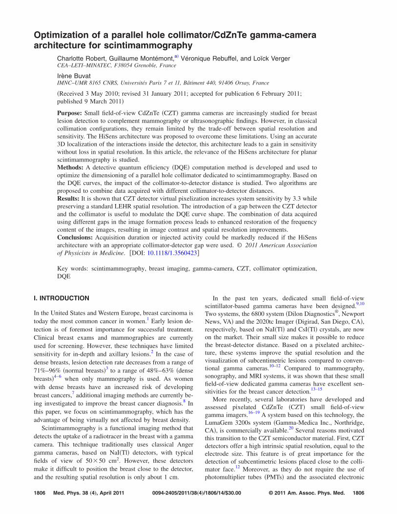
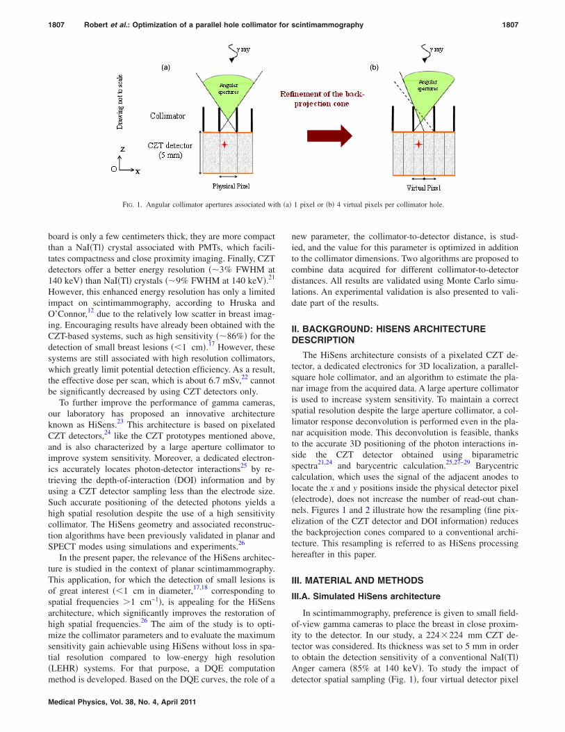
The HiSens architecture consists of a pixelated CZT de-tector, a dedicated electronics for 3D localization, a parallel-square hole collimator, and an algorithm to estimate the pla-nar image from the acquired data. A large aperture collimatoris used to increase system sensitivity. To maintain a correctspatial resolution despite the large aperture collimator, a col-limator response deconvolution is performed even in the pla-nar acquisition mode. This deconvolution is feasible, thanksto the accurate 3D positioning of the photon interactions in-side the CZT detector obtained using biparametricspectra21,24 and barycentric calculation.25,27–29 Barycentriccalculation, which uses the signal of the adjacent anodes tolocate the x and y positions inside the physical detector pixel�electrode�, does not increase the number of read-out chan-nels. Figures 1 and 2 illustrate how the resampling �fine pix-elization of the CZT detector and DOI information� reducesthe backprojection cones compared to a conventional archi-tecture. This resampling is referred to as HiSens processinghereafter in this paper.
III. MATERIAL AND METHODS
III.A. Simulated HiSens architecture
In scintimammography, preference is given to small field-of-view gamma cameras to place the breast in close proxim-ity to the detector. In our study, a 224�224 mm CZT de-tector was considered. Its thickness was set to 5 mm in orderto obtain the detection sensitivity of a conventional NaI�Tl�Anger camera �85% at 140 keV�. To study the impact of
1 pixel or �b� 4 virtual pixels per collimator hole.
detector spatial sampling �Fig. 1�, four virtual detector pixel
�a� on
1808 Robert et al.: Optimization of a parallel hole collimator for scintimammography 1808
sizes were considered: 1.6, 0.8, 0.4, and 0.2 mm, which cor-responded to 1, 4, 16, and 64 virtual pixels per collimatorhole, respectively. The detector was also divided into threeequally sensitive virtual layers �the thickness of each layerwas set in such a way that layers detected equal numbers ofphotons� to take advantage of the DOI information. Finally, aconfiguration with only one 5 mm thick CZT detector layerwas studied as a reference.
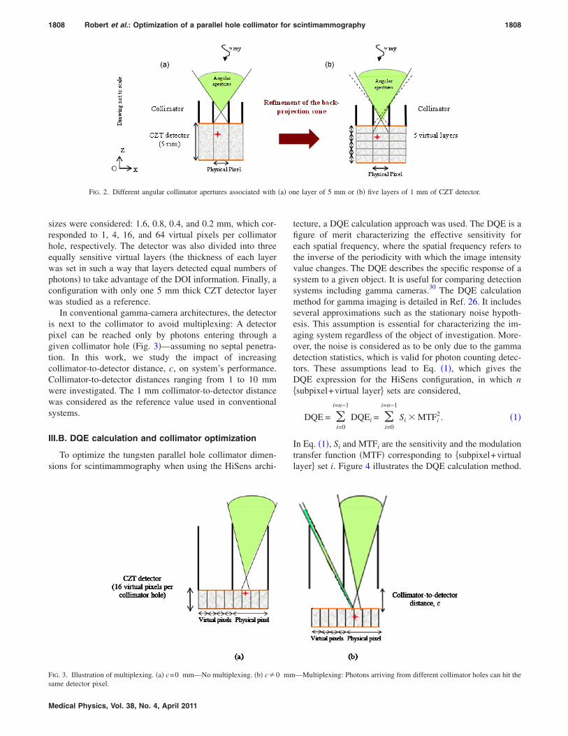
In conventional gamma-camera architectures, the detectoris next to the collimator to avoid multiplexing: A detectorpixel can be reached only by photons entering through agiven collimator hole �Fig. 3�—assuming no septal penetra-tion. In this work, we study the impact of increasingcollimator-to-detector distance, c, on system’s performance.Collimator-to-detector distances ranging from 1 to 10 mmwere investigated. The 1 mm collimator-to-detector distancewas considered as the reference value used in conventionalsystems.
III.B. DQE calculation and collimator optimization
To optimize the tungsten parallel hole collimator dimen-sions for scintimammography when using the HiSens archi-
FIG. 2. Different angular collimator apertures associated with
tecture, a DQE calculation approach was used. The DQE is afigure of merit characterizing the effective sensitivity foreach spatial frequency, where the spatial frequency refers tothe inverse of the periodicity with which the image intensityvalue changes. The DQE describes the specific response of asystem to a given object. It is useful for comparing detectionsystems including gamma cameras.30 The DQE calculationmethod for gamma imaging is detailed in Ref. 26. It includesseveral approximations such as the stationary noise hypoth-esis. This assumption is essential for characterizing the im-aging system regardless of the object of investigation. More-over, the noise is considered as to be only due to the gammadetection statistics, which is valid for photon counting detec-tors. These assumptions lead to Eq. �1�, which gives theDQE expression for the HiSens configuration, in which n�subpixel+virtual layer� sets are considered,
DQE = �i=0
i=n−1
DQEi = �i=0
i=n−1
Si � MTFi2. �1�
In Eq. �1�, Si and MTFi are the sensitivity and the modulationtransfer function �MTF� corresponding to �subpixel+virtuallayer� set i. Figure 4 illustrates the DQE calculation method.
e layer of 5 mm or �b� five layers of 1 mm of CZT detector.
—Multiplexing: Photons arriving from different collimator holes can hit the
mm
1809 Robert et al.: Optimization of a parallel hole collimator for scintimammography 1809
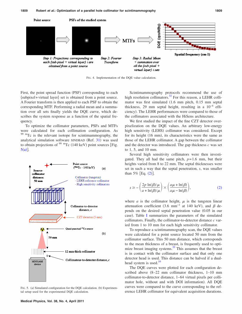
First, the point spread function �PSF� corresponding to each�subpixel+virtual layer� set is obtained from a point source.A Fourier transform is then applied to each PSF to obtain thecorresponding MTF. Performing a radial mean and a summa-tion over all sets finally yields the DQE curve, which de-scribes the system response as a function of the spatial fre-quency.
To optimize the collimator parameters, PSFs and MTFswere calculated for each collimation configuration. As99 mTc is the relevant isotope for scintimammography, theanalytical simulation software SINDBAD �Ref. 31� was usedto obtain projections of 99 mTc �140 keV� point sources �Fig.5�a��.
FIG. 4. Implementation o
FIG. 5. �a� Simulated configuration for the DQE calculation. �b� Experimen-
tal setup used for the experimental DQE calculation.
Medical Physics, Vol. 38, No. 4, April 2011
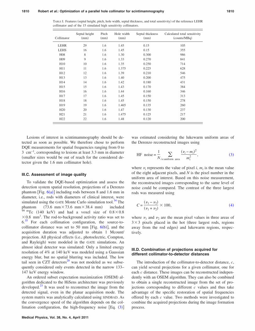
Scintimammography protocols recommend the use ofhigh resolution collimators.32 For this reason, a LEHR colli-mator was first simulated �1.6 mm pitch, 0.15 mm septalthickness, 29 mm septal height, resulting in a 10−4 effi-ciency�. The LEHR performances were compared to those ofthe collimators associated with the HiSens architecture.
We first studied the impact of the fine CZT detector over-pixelization on the DQE values. An arbitrary low-energyhigh sensitivity �LEHS� collimator was considered. Exceptfor its height �16 mm�, its characteristics were the same asthose of the LEHR collimator. A gap between the collimatorand the detector was introduced. The gap thickness c was setto 1, 5, and 10 mm.
Several high sensitivity collimators were then investi-gated. They all had the same pitch, p=1.6 mm, but theirheights varied from 8 to 22 mm. The septal thicknesses wereset in such a way that the septal penetration, s, was smallerthan 5% �Eq. �2��.
s � − 2p ln���/�a + ln���/� � a� + ln���
a� − ln��� , �2�
where a is the collimator height, � is the tungsten linearattenuation coefficient �3.6 mm−1 at 140 keV�, and � de-pends on the desired septal penetration value �0.05 in ourcase�. Table I summarizes the parameters of the simulatedcollimators. Finally, the collimator-to-detector distance c var-ied from 1 to 10 mm for each high sensitivity collimator.
To reproduce a scintimammography scan, the DQE valueswere calculated for a point source located 50 mm from thecollimator surface. This 50 mm distance, which correspondsto the mean thickness of a breast, is frequently used to opti-mize breast imaging systems.33 This assumes that the breastis in contact with the collimator surface and that only onedetector head is used. This distance can be halved if a dual-head system is used.16
The DQE curves were plotted for each configuration de-scribed above �8–22 mm collimator thickness, 1–10 mmcollimator-to-detector distance, 1–64 virtual pixels per colli-mator hole, without and with DOI information�. All DQEcurves were compared to the curve corresponding to the ref-
DQE value calculation.
f the
erence LEHR collimator for equivalent acquisition durations.
1810 Robert et al.: Optimization of a parallel hole collimator for scintimammography 1810
Lesions of interest in scintimammography should be de-tected as soon as possible. We therefore chose to performDQE measurements for spatial frequencies ranging from 0 to3 cm−1, corresponding to lesions at least 3.3 mm in diameter�smaller sizes would be out of reach for the considered de-tector given the 1.6 mm collimator hole�.
III.C. Assessment of image quality
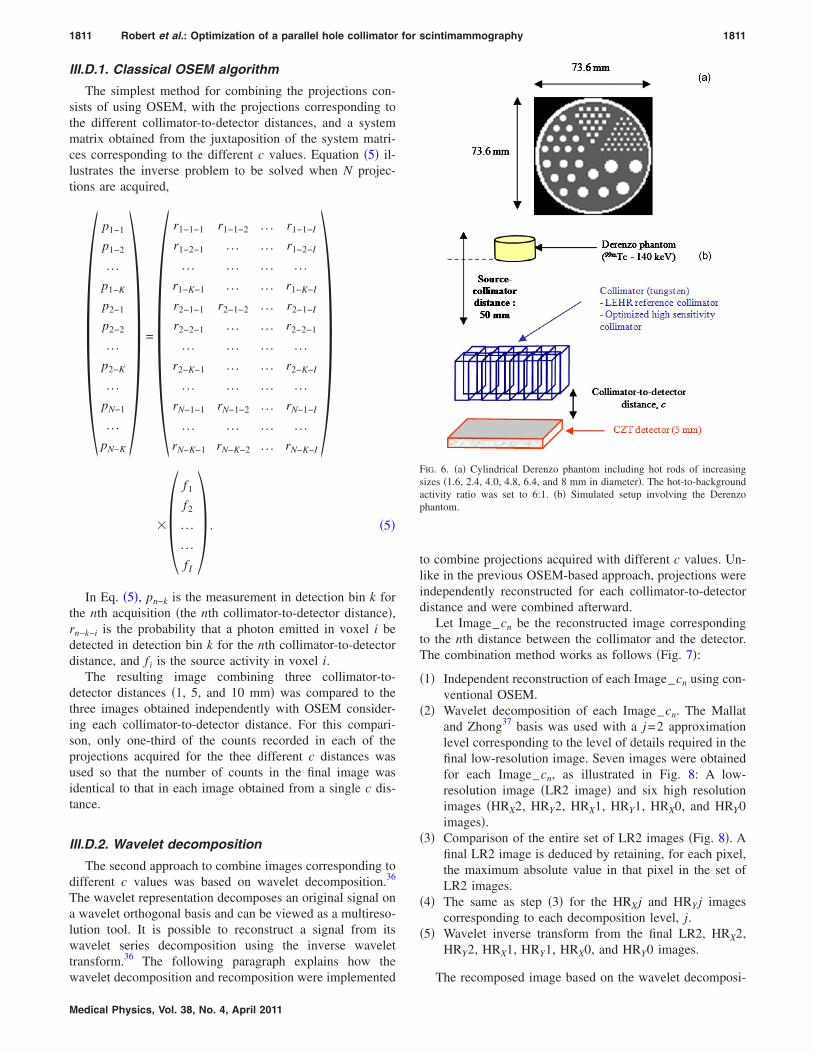
To validate the DQE-based optimization and assess thedetection system spatial resolution, projections of a Derenzophantom �Fig. 6�a�� including rods between 8 and 1.6 mm indiameter, i.e., rods with diameters of clinical interest, weresimulated using the GATE Monte Carlo simulation tool.34 Thephantom �73.6 mm�73.6 mm�38.4 mm� included99 mTc �140 keV� and had a voxel size of 0.8�0.8�0.8 mm3. The rod-to-background activity ratio was set to6.35 For each collimation configuration, the source-to-collimator distance was set to 50 mm �Fig. 6�b��, and theacquisition duration was adjusted to obtain 1 Mcount/projection. All physical effects �i.e., photoelectric, Compton,and Rayleigh� were modeled in the GATE simulations. Analmost ideal detector was simulated: Only a limited energyresolution of 4% at 140 keV was modeled using a Gaussianenergy blur, but no spatial blurring was included. The lowtail seen in CZT detectors20 was not modeled as we subse-quently considered only events detected in the narrow 133–147 keV energy window.
An ordered subset expectation maximization �OSEM� al-gorithm dedicated to the HiSens architecture was previouslydeveloped.23 It was used to reconstruct the image from thedetected signal, even in the planar acquisition mode. Thesystem matrix was analytically calculated using SINDBAD. Asthe convergence speed of the algorithm depends on the col-
TABLE I. Features �septal height, pitch, hole width, sepcollimator and of the 15 simulated high sensitivity c
limation configuration, the high-frequency noise �Eq. �3��
Medical Physics, Vol. 38, No. 4, April 2011
was estimated considering the lukewarm uniform areas ofthe Derenzo reconstructed images using
HF noise =1
N�
i�uniform area
��i − mi�2
mi2 , �3�
where �i represents the value of pixel i, mi is the mean valueof the eight adjacent pixels, and N is the pixel number in theuniform area of interest. Based on this noise measurement,the reconstructed images corresponding to the same level ofnoise could be compared. The contrast of the three largestrods was measured using
C =��1 − �2���1 + �2�
� 100, �4�
where �1 and �2 are the mean pixel values in three areas of3�3 pixels placed in the hot �three largest rods, regionsaway from the rod edges� and lukewarm regions, respec-tively.
III.D. Combination of projections acquired fordifferent collimator-to-detector distances
The introduction of the collimator-to-detector distance, c,can yield several projections for a given collimator, one foreach c distance. These images can be reconstructed indepen-dently with an OSEM algorithm. They can also be combinedto obtain a single reconstructed image from the set of pro-jections corresponding to different c values and thus takeadvantage of the specific restoration of spatial frequenciesoffered by each c value. Two methods were investigated tocombine the acquired projections during the image formation
ickness, and total sensitivity� of the reference LEHRators.
1811 Robert et al.: Optimization of a parallel hole collimator for scintimammography 1811
III.D.1. Classical OSEM algorithm
The simplest method for combining the projections con-sists of using OSEM, with the projections corresponding tothe different collimator-to-detector distances, and a systemmatrix obtained from the juxtaposition of the system matri-ces corresponding to the different c values. Equation �5� il-lustrates the inverse problem to be solved when N projec-tions are acquired,
�p1−1
p1−2
. . .
p1−K
p2−1
p2−2
. . .
p2−K
. . .
pN−1
. . .
pN−K
� =�r1−1−1 r1−1−2 . . . r1−1−I
r1−2−1 . . . . . . r1−2−I
. . . . . . . . . . . .
r1−K−1 . . . . . . r1−K−I
r2−1−1 r2−1−2 . . . r2−1−I
r2−2−1 . . . . . . r2−2−1
. . . . . . . . . . . .
r2−K−1 . . . . . . r2−K−I
. . . . . . . . . . . .
rN−1−1 rN−1−2 . . . rN−1−I
. . . . . . . . . . . .
rN−K−1 rN−K−2 . . . rN−K−I
���
f1
f2
. . .
. . .
f I
� . �5�
In Eq. �5�, pn−k is the measurement in detection bin k forthe nth acquisition �the nth collimator-to-detector distance�,rn−k−i is the probability that a photon emitted in voxel i bedetected in detection bin k for the nth collimator-to-detectordistance, and f i is the source activity in voxel i.
The resulting image combining three collimator-to-detector distances �1, 5, and 10 mm� was compared to thethree images obtained independently with OSEM consider-ing each collimator-to-detector distance. For this compari-son, only one-third of the counts recorded in each of theprojections acquired for the thee different c distances wasused so that the number of counts in the final image wasidentical to that in each image obtained from a single c dis-tance.
III.D.2. Wavelet decomposition
The second approach to combine images corresponding todifferent c values was based on wavelet decomposition.36
The wavelet representation decomposes an original signal ona wavelet orthogonal basis and can be viewed as a multireso-lution tool. It is possible to reconstruct a signal from itswavelet series decomposition using the inverse wavelettransform.36 The following paragraph explains how the
wavelet decomposition and recomposition were implemented
Medical Physics, Vol. 38, No. 4, April 2011
to combine projections acquired with different c values. Un-like in the previous OSEM-based approach, projections wereindependently reconstructed for each collimator-to-detectordistance and were combined afterward.
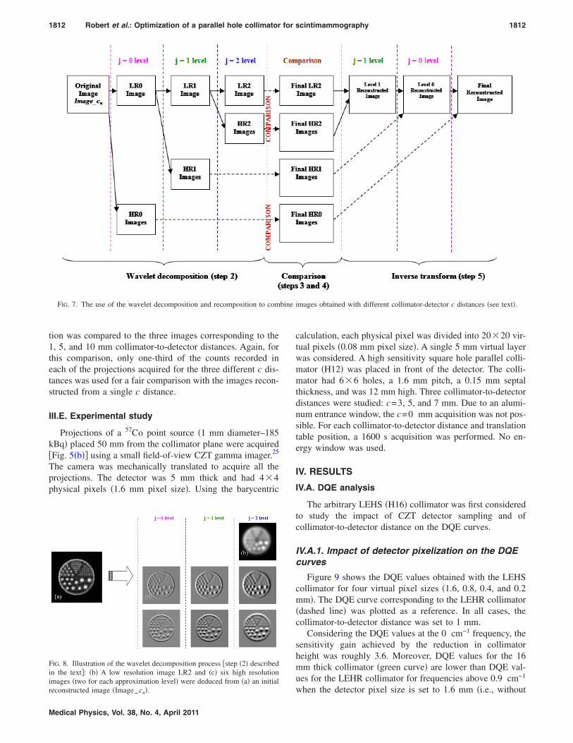
Let Image_cn be the reconstructed image correspondingto the nth distance between the collimator and the detector.The combination method works as follows �Fig. 7�:
�1� Independent reconstruction of each Image_cn using con-ventional OSEM.
�2� Wavelet decomposition of each Image_cn. The Mallatand Zhong37 basis was used with a j=2 approximationlevel corresponding to the level of details required in thefinal low-resolution image. Seven images were obtainedfor each Image_cn, as illustrated in Fig. 8: A low-resolution image �LR2 image� and six high resolutionimages �HRX2, HRY2, HRX1, HRY1, HRX0, and HRY0images�.
�3� Comparison of the entire set of LR2 images �Fig. 8�. Afinal LR2 image is deduced by retaining, for each pixel,the maximum absolute value in that pixel in the set ofLR2 images.
�4� The same as step �3� for the HRXj and HRY j imagescorresponding to each decomposition level, j.
�5� Wavelet inverse transform from the final LR2, HRX2,HRY2, HRX1, HRY1, HRX0, and HRY0 images.
FIG. 6. �a� Cylindrical Derenzo phantom including hot rods of increasingsizes �1.6, 2.4, 4.0, 4.8, 6.4, and 8 mm in diameter�. The hot-to-backgroundactivity ratio was set to 6:1. �b� Simulated setup involving the Derenzophantom.
The recomposed image based on the wavelet decomposi-
bine
1812 Robert et al.: Optimization of a parallel hole collimator for scintimammography 1812
tion was compared to the three images corresponding to the1, 5, and 10 mm collimator-to-detector distances. Again, forthis comparison, only one-third of the counts recorded ineach of the projections acquired for the three different c dis-tances was used for a fair comparison with the images recon-structed from a single c distance.
III.E. Experimental study
Projections of a 57Co point source �1 mm diameter–185kBq� placed 50 mm from the collimator plane were acquired�Fig. 5�b�� using a small field-of-view CZT gamma imager.25
The camera was mechanically translated to acquire all theprojections. The detector was 5 mm thick and had 4�4physical pixels �1.6 mm pixel size�. Using the barycentric
FIG. 7. The use of the wavelet decomposition and recomposition to com
FIG. 8. Illustration of the wavelet decomposition process �step �2� describedin the text�: �b� A low resolution image LR2 and �c� six high resolutionimages �two for each approximation level� were deduced from �a� an initial
reconstructed image �Image_cn�.
Medical Physics, Vol. 38, No. 4, April 2011
calculation, each physical pixel was divided into 20�20 vir-tual pixels �0.08 mm pixel size�. A single 5 mm virtual layerwas considered. A high sensitivity square hole parallel colli-mator �H12� was placed in front of the detector. The colli-mator had 6�6 holes, a 1.6 mm pitch, a 0.15 mm septalthickness, and was 12 mm high. Three collimator-to-detectordistances were studied: c=3, 5, and 7 mm. Due to an alumi-num entrance window, the c=0 mm acquisition was not pos-sible. For each collimator-to-detector distance and translationtable position, a 1600 s acquisition was performed. No en-ergy window was used.
IV. RESULTS
IV.A. DQE analysis
The arbitrary LEHS �H16� collimator was first consideredto study the impact of CZT detector sampling and ofcollimator-to-detector distance on the DQE curves.
IV.A.1. Impact of detector pixelization on the DQEcurves
Figure 9 shows the DQE values obtained with the LEHScollimator for four virtual pixel sizes �1.6, 0.8, 0.4, and 0.2mm�. The DQE curve corresponding to the LEHR collimator�dashed line� was plotted as a reference. In all cases, thecollimator-to-detector distance was set to 1 mm.
Considering the DQE values at the 0 cm−1 frequency, thesensitivity gain achieved by the reduction in collimatorheight was roughly 3.6. Moreover, DQE values for the 16mm thick collimator �green curve� are lower than DQE val-ues for the LEHR collimator for frequencies above 0.9 cm−1
images obtained with different collimator-detector c distances �see text�.
when the detector pixel size is set to 1.6 mm �i.e., without
1813 Robert et al.: Optimization of a parallel hole collimator for scintimammography 1813
HiSens processing�. As expected, restoration of high spatialfrequencies is markedly reduced if only a large aperture col-limator is used. Spatial resampling of the CZT detector �0.8,0.4, and 0.2 mm virtual pixels� increases the DQE values�Fig. 9�. Virtual pixel size was therefore set to 0.2 mm �64virtual pixels per collimator hole� in the remainder of thisstudy.
IV.A.2. Impact of collimator-to-detector distance onthe DQE curves
Figure 10 shows the DQE values obtained with the LEHScollimator when the collimator-to-detector distance was setto 1 and 10 mm, without HiSens processing �1 DOI—1.6mm pixel size�. DQE values corresponding to c=10 mm arelower than DQE values obtained for c=1 mm. This explainswhy no gap between the collimator and the detector has beenintroduced in the gamma camera up to now.
Figure 11 shows the DQE curves corresponding to theLEHS collimator when HiSens processing was used �3 DOI–0.2 mm virtual pixel size�, and a gap between the collimator
FIG. 9. DQE measured for a 50 mm source-to-collimator distance for twocollimation settings �septal heights of 29 and 16 mm�. For the LEHR colli-mator, pixel size was set to 1.6 mm. For the LEHS, four virtual pixel sizeswere studied: 1.6, 0.8, 0.4, and 0.2 mm.
FIG. 10. DQE measured for a 50 mm source-to-collimator distance with theLEHS �H16� collimator for two collimator-to-detector distances: c=1 mm
and c=10 mm, without HiSens processing.
Medical Physics, Vol. 38, No. 4, April 2011
and the detector was introduced �c=1, 5, and 10 mm�. TheDQE curve corresponding to the LEHR collimator is plottedas a reference. The shape of the DQE curves is modulateddepending on collimator-to-detector distance. Consideringthe LEHS–c=10 mm configuration, the gap between thecollimator and the detector decreases the low-frequencyDQE values and increases the high-frequency DQE valuescompared to smaller gaps. Moreover, comparing theLEHS–c=5 mm and the LEHR DQE curves, the 5 mmcollimator-to-detector distance yields greater DQE values forall frequencies of interest.
IV.B. Collimator optimization
Figure 12 compares the DQE curves corresponding toseveral collimation configurations for a source-to-collimator
FIG. 11. DQE measured for a 50 mm source-to-collimator distance with theLEHR �H29� and the LEHS �H16� collimators. For the LEHR collimator, noHiSens processing was used and c=1 mm. For the LEHS collimator, HiS-ens processing was used �3 DOI–0.2 mm virtual pixel size� and threecollimator-to-detector distances �c=1, 5, and 10 mm� were studied.
FIG. 12. DQE measured for a source-to-collimator distance of 50 mm withthe LEHR �H29� and the high sensitivity collimators. For the LEHR colli-mator, no HiSens processing was used. For the high sensitivity collimators,HiSens processing was used �3 DOI–0.2 mm virtual pixel size�. c was set to
1 mm in all configurations.
1814 Robert et al.: Optimization of a parallel hole collimator for scintimammography 1814
distance of 50 mm and a collimator-to-detector distance of 1mm when HiSens processing is used. The LEHR collimatorcurve is plotted as a reference.
A desirable collimator should recover or improve thehigh-frequency content �measurable, thanks to the DQE val-ues� captured by the reference LEHR collimator �Eq. �6��with a maximum sensitivity gain �Eq. �7��. Comparing allcurves plotted in Fig. 12, the H17 collimator fulfills thesecriteria �Fig. 13�. A 3.3 increase in detection sensitivity cantherefore be achieved while maintaining the spatial reso-lution of the LEHR collimator,
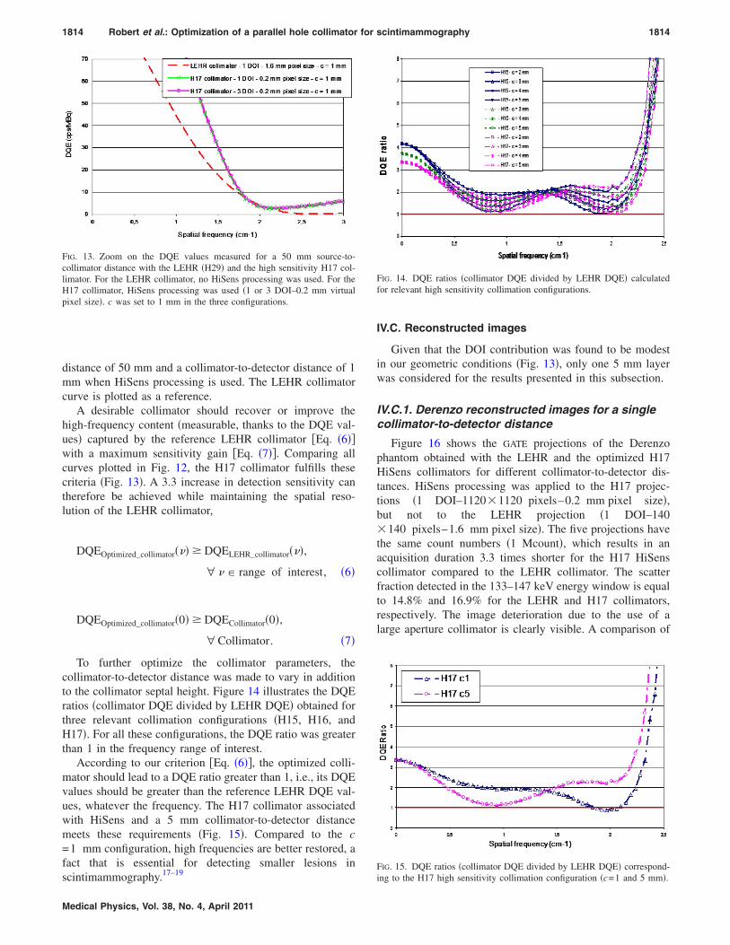
To further optimize the collimator parameters, thecollimator-to-detector distance was made to vary in additionto the collimator septal height. Figure 14 illustrates the DQEratios �collimator DQE divided by LEHR DQE� obtained forthree relevant collimation configurations �H15, H16, andH17�. For all these configurations, the DQE ratio was greaterthan 1 in the frequency range of interest.
According to our criterion �Eq. �6��, the optimized colli-mator should lead to a DQE ratio greater than 1, i.e., its DQEvalues should be greater than the reference LEHR DQE val-ues, whatever the frequency. The H17 collimator associatedwith HiSens and a 5 mm collimator-to-detector distancemeets these requirements �Fig. 15�. Compared to the c=1 mm configuration, high frequencies are better restored, afact that is essential for detecting smaller lesions in
17–19
FIG. 13. Zoom on the DQE values measured for a 50 mm source-to-collimator distance with the LEHR �H29� and the high sensitivity H17 col-limator. For the LEHR collimator, no HiSens processing was used. For theH17 collimator, HiSens processing was used �1 or 3 DOI–0.2 mm virtualpixel size�. c was set to 1 mm in the three configurations.
scintimammography.
Medical Physics, Vol. 38, No. 4, April 2011
IV.C. Reconstructed images
Given that the DOI contribution was found to be modestin our geometric conditions �Fig. 13�, only one 5 mm layerwas considered for the results presented in this subsection.
IV.C.1. Derenzo reconstructed images for a singlecollimator-to-detector distance
Figure 16 shows the GATE projections of the Derenzophantom obtained with the LEHR and the optimized H17HiSens collimators for different collimator-to-detector dis-tances. HiSens processing was applied to the H17 projec-tions �1 DOI–1120�1120 pixels–0.2 mm pixel size�,but not to the LEHR projection �1 DOI–140�140 pixels–1.6 mm pixel size�. The five projections havethe same count numbers �1 Mcount�, which results in anacquisition duration 3.3 times shorter for the H17 HiSenscollimator compared to the LEHR collimator. The scatterfraction detected in the 133–147 keV energy window is equalto 14.8% and 16.9% for the LEHR and H17 collimators,respectively. The image deterioration due to the use of alarge aperture collimator is clearly visible. A comparison of
FIG. 14. DQE ratios �collimator DQE divided by LEHR DQE� calculatedfor relevant high sensitivity collimation configurations.
ing to the H17 high sensitivity collimation configuration �c=1 and 5 mm�.
1815 Robert et al.: Optimization of a parallel hole collimator for scintimammography 1815
Figs. 16�c�–16�e� illustrates the multiplexing phenomenon:The gap between the collimator and the detector leads toblurred images.
Figure 17 compares the reconstructed images of the Der-enzo phantom corresponding to the LEHR and the optimizedH17 HiSens collimators for the same level of noise in thereconstructed images. When a conventional architecture �1.6mm pixel size� is associated with the 17 mm thick collimator,the image quality is inferior to that obtained with the LEHRcollimator. However, when the HiSens architecture �0.2 mmvirtual pixel size� is associated with the H17 collimator, the
FIG. 16. GATE projections of the Derenzo phantom acquired with �a� theLEHR collimator–1.6 mm detector pixel size–c=1 mm, �b� the H17collimator–1.6 mm detector pixel size–c=1 mm, �c� the H17 collimator–0.2mm detector pixel size–c=1 mm, �d� the H17 collimator–0.2 mm detectorpixel size–c=5 mm, and �e� the H17 collimator–0.2 mm detector pixelsize–c=10 mm.
FIG. 17. Reconstructed images of the Derenzo phantom with the same no
GATE-simulated projections used here had the same number of counts �1 Mcount
Medical Physics, Vol. 38, No. 4, April 2011
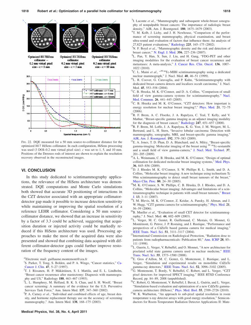
image features are markedly improved. Comparison of thelast three columns of Fig. 17, which correspond to threedifferent collimator-to-detector distances, shows that increas-ing c has a favorable effect on the high-frequency rod imagecontrast. The 4.0 mm rods �yellow arrow� are more visiblewith a 5 mm gap than with a classical 1 mm gap between thecollimator and the detector. The contrast of the largest rods isslightly deteriorated due to this increased gap �see dashedarrow and contrast values�. We checked that these resultsremained unchanged when a lower noise level �i.e., a smallernumber of iterations� for each method is considered �resultsnot shown�.
Considering the DQE curves, the H17 collimator associ-ated with the HiSens architecture and a collimator-to-detector distance of 5 mm was defined as the optimized col-limation configuration. Figure 17 shows that the contrast inthe 4.0 mm rods observed with the reference collimator isrecovered when this optimized collimation configuration isused. Moreover, the smallest rods �1.6 and 2.4 mm�, whichcorrespond to the highest frequencies, are slightly better re-covered with the optimized H17 HiSens collimator than withthe reference LEHR collimator. These results are consistentwith the DQE analysis �see Sec. V�.
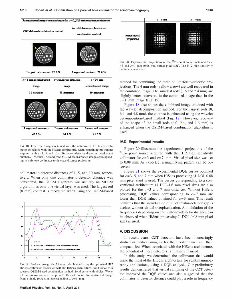
Figure 18 shows the image obtained with the adaptedOSEM algorithm �see Sec. III D 1�, which combines thethree HiSens H17 projections �c=1, 5, and 10 mm�. Onlyone-third of each projection count number was used for a faircomparison with the reconstructed images corresponding to
evel. Images are shown using common min and max for all images. All
ise l �.
1816 Robert et al.: Optimization of a parallel hole collimator for scintimammography 1816
collimator-to-detector distances of 1, 5, and 10 mm, respec-tively. When only one collimator-to-detector distance wasconsidered, the OSEM algorithm was actually an MLEMalgorithm as only one virtual layer was used. The largest rod�8 mm� contrast is recovered when using the OSEM-based
FIG. 19. Profiles through the 2.4 mm rods obtained using the optimized H17HiSens collimator associated with the HiSens architecture. Solid curve withsquares: OSEM-based combination method. Solid curve with circles: Wave-let decomposition-based approach. Dashed curve: Reconstructed image
FIG. 18. First row: Images obtained with the optimized H17 HiSens colli-mator associated with the HiSens architecture, when combining projectionsacquired with c=1, 5, and 10 collimator-to-detector distances �total countnumber=1 Mcount�. Second row: MLEM reconstructed images correspond-ing to only one collimator-to-detector distance projection.
from a single projection corresponding to c=1 mm.
Medical Physics, Vol. 38, No. 4, April 2011
method for combining the three collimator-to-detector pro-jections. The 4 mm rods �yellow arrow� are well recovered inthe combined image. The smallest rods �1.6 and 2.4 mm� areslightly better recovered in the combined image than in thec=1 mm image �Fig. 19�.
Figure 18 also shows the combined image obtained withthe wavelet decomposition method. For the largest rods �8,6.4, and 4.8 mm�, the contrast is enhanced using the waveletdecomposition-based method �Fig. 18�. However, recoveryof the shape of the small rods �4.0, 2.4, and 1.6 mm� isenhanced when the OSEM-based combination algorithm isused.
IV.D. Experimental results
Figure 20 illustrates the experimental projections of the57Co point source acquired with the H12 high sensitivitycollimator for c=3 and c=7 mm. Virtual pixel size was setto 0.08 mm. As expected, a magnifying pattern can be ob-served.
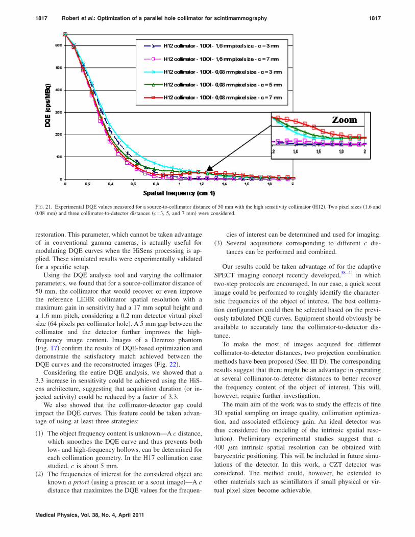
Figure 21 shows the experimental DQE curves obtainedfor c=3, 5, and 7 mm when HiSens processing �1 DOI–0.08mm pixel size� is used. The curves corresponding to a con-ventional architecture �1 DOI–1.6 mm pixel size� are alsoplotted for the c=3 and 7 mm distances. Without HiSensprocessing, DQE values corresponding to c=7 mm arelower than DQE values obtained for c=3 mm. This resultconfirms that the introduction of a collimator-detector gap isuseless without virtual overpixelization. A modulation of thefrequencies depending on collimator-to-detector distance canbe observed when HiSens processing �1 DOI–0.08 mm pixelsize� is used.
V. DISCUSSION
In recent years, CZT detectors have been increasinglystudied in medical imaging for their performance and theircompact size. When associated with the HiSens architecture,the potential of these detectors is further enhanced.
In this study, we determined the collimator that wouldmake the most of the HiSens architecture for scintimammog-raphy applications, using a DQE analysis. Our preliminaryresults demonstrated that virtual sampling of the CZT detec-tor improved the DQE values and also suggested that the
FIG. 20. Experimental projections of the 57Co point source obtained for c=3 and c=7 mm �0.08 mm virtual pixel size�. The H12 high sensitivitycollimator was used.
collimator-to-detector distance could play a role in frequency
re co
1817 Robert et al.: Optimization of a parallel hole collimator for scintimammography 1817
restoration. This parameter, which cannot be taken advantageof in conventional gamma cameras, is actually useful formodulating DQE curves when the HiSens processing is ap-plied. These simulated results were experimentally validatedfor a specific setup.
Using the DQE analysis tool and varying the collimatorparameters, we found that for a source-collimator distance of50 mm, the collimator that would recover or even improvethe reference LEHR collimator spatial resolution with amaximum gain in sensitivity had a 17 mm septal height anda 1.6 mm pitch, considering a 0.2 mm detector virtual pixelsize �64 pixels per collimator hole�. A 5 mm gap between thecollimator and the detector further improves the high-frequency image content. Images of a Derenzo phantom�Fig. 17� confirm the results of DQE-based optimization anddemonstrate the satisfactory match achieved between theDQE curves and the reconstructed images �Fig. 22�.
Considering the entire DQE analysis, we showed that a3.3 increase in sensitivity could be achieved using the HiS-ens architecture, suggesting that acquisition duration �or in-jected activity� could be reduced by a factor of 3.3.
We also showed that the collimator-detector gap couldimpact the DQE curves. This feature could be taken advan-tage of using at least three strategies:
�1� The object frequency content is unknown—A c distance,which smoothes the DQE curve and thus prevents bothlow- and high-frequency hollows, can be determined foreach collimation geometry. In the H17 collimation casestudied, c is about 5 mm.
�2� The frequencies of interest for the considered object areknown a priori �using a prescan or a scout image�—A c
FIG. 21. Experimental DQE values measured for a source-to-collimator dista0.08 mm� and three collimator-to-detector distances �c=3, 5, and 7 mm� we
distance that maximizes the DQE values for the frequen-
Medical Physics, Vol. 38, No. 4, April 2011
cies of interest can be determined and used for imaging.�3� Several acquisitions corresponding to different c dis-
tances can be performed and combined.
Our results could be taken advantage of for the adaptiveSPECT imaging concept recently developed,38–41 in whichtwo-step protocols are encouraged. In our case, a quick scoutimage could be performed to roughly identify the character-istic frequencies of the object of interest. The best collima-tion configuration could then be selected based on the previ-ously tabulated DQE curves. Equipment should obviously beavailable to accurately tune the collimator-to-detector dis-tance.
To make the most of images acquired for differentcollimator-to-detector distances, two projection combinationmethods have been proposed �Sec. III D�. The correspondingresults suggest that there might be an advantage in operatingat several collimator-to-detector distances to better recoverthe frequency content of the object of interest. This will,however, require further investigation.
The main aim of the work was to study the effects of fine3D spatial sampling on image quality, collimation optimiza-tion, and associated efficiency gain. An ideal detector wasthus considered �no modeling of the intrinsic spatial reso-lution�. Preliminary experimental studies suggest that a400 �m intrinsic spatial resolution can be obtained withbarycentric positioning. This will be included in future simu-lations of the detector. In this work, a CZT detector wasconsidered. The method could, however, be extended toother materials such as scintillators if small physical or vir-
f 50 mm with the high sensitivity collimator �H12�. Two pixel sizes �1.6 andnsidered.
nce o
tual pixel sizes become achievable.
1818 Robert et al.: Optimization of a parallel hole collimator for scintimammography 1818
VI. CONCLUSION
In this study dedicated to scintimammography applica-tions, the relevance of the HiSens architecture was demon-strated. DQE computations and Monte Carlo simulationsboth showed that accurate 3D positioning of interactions inthe CZT detector associated with an appropriate collimator-detector gap made it possible to increase detection sensitivitywhile maintaining or improving the spatial resolution of areference LEHR collimator. Considering a 50 mm source-collimator distance, we showed that an increase in sensitivityby a factor of 3.3 could be achieved, suggesting that acqui-sition duration or injected activity could be markedly re-duced if this HiSens architecture was used. Processing ap-proaches to make the most of the acquired data were alsopresented and showed that combining data acquired with dif-ferent collimator-detector gaps could further improve resto-ration of the frequency content of the images.
a�Electronic mail: [email protected]. Parker, T. Tong, S. Bolden, and P. A. Wingo, “Cancer statistics,” Ca-Cancer J. Clin. 47, 5–27 �1997�.
2T. J. Rissanen, H. P. Mäkäräinen, S. I. Mattila, and E. L. Lindholm,“Breast cancer recurrence after mastectomy: Diagnosis with mammogra-phy and US,” Radiology 188, 463–467 �1993�.
3L. L. Humphrey, M. Helfand, B. K. S. Chan, and S. H. Woolf, “Breastcancer screening: A summary of the evidence for the U.S. PreventiveServices Task Force,” Ann. Intern Med. 137, 347–360 �2002�.
4P. A. Carney et al., “Individual and combined effects of age, breast den-sity, and hormone replacement therapy use on the accuracy of screening
FIG. 22. DQE measured for a 50 mm source-to-collimator distance for theoptimized H17 HiSens collimator. In each configuration, HiSens processingwas used �3 DOI–0.2 mm virtual pixel size�. c was set to 1, 5, and 10 mm.Positions of the Derenzo rods of interest are shown to explain the resolutionrecovery observed in the reconstructed images.
mammography,” Ann. Intern Med. 138, 168–175 �2003�.
Medical Physics, Vol. 38, No. 4, April 2011
5I. Laconte et al., “Mammography and subsequent whole-breast sonogra-phy of nonpalpable breast cancers: The importance of radiologic breastdensity,” AJR, Am. J. Roentgenol. 180, 1675–1679 �2003�.
6T. M. Kolb, J. Lichy, and J. H. Newhouse, “Comparison of the perfor-mance of screening mammography, physical examination, and breastultra-sound and evaluation of factors that influence them: An analysis of27,825 patient evaluations,” Radiology 225, 165–175 �2002�.
7N. F. Boyd et al., “Mammographic density and the risk and detection ofbreast cancer,” N. Engl. J. Med. 356, 227–236 �2007�.
8L. Pan, Y. Han, X. Sun, J. Liu, and H. Gang, “FDG-PET and otherimaging modalities for the evaluation of breast cancer recurrence andmetastases: A meta-analysis,” J. Cancer Res. Clin. Oncol. 136, 1007–1022 �2010�.
9C. L. Maini et al., “99-mTc-MIBI scintimammography using a dedicatednuclear mammograph,” J. Nucl. Med. 40, 46–51 �1999�.
10L. R. Coover, G. Caravaglia, and P. Kuhn, “Scintimammography withdedicated breast camera detects and localizes occult carcinoma,” J. Nucl.Med. 45, 553–558 �2004�.
11C. B. Hruska, M. K. O’Connor, and D. A. Collins, “Comparison of smallfield of view gamma-camera systems for scintimammography,” Nucl.Med. Commun. 26, 441–445 �2005�.
12C. B. Hruska and M. K. O’Connor, “CZT detectors: How important isenergy resolution for nuclear breast imaging?,” Phys. Med. 21, 72–75�2006�.
13R. F. Brem, A. C. Floerke, J. A. Rapelyea, C. Teal, T. Kelly, and V.Mathur, “Breast-specific gamma imaging as an adjunct imaging modalityfor the diagnosis of breast cancer,” Radiology 247, 651–657 �2008�.
14R. F. Brem, M. Loffe, J. A. Rapelyea, K. G. Yost, J. M. Weigert, M. L.Bertrand, and L. H. Stern, “Invasive lobular carcinoma: Detection withmammography, sonography, MRI, and breast-specific gamma imaging,”AJR, Am. J. Roentgenol. 192, 379–383 �2009�.
15E. A. Jones, T. D. Phan, D. A. Blanchard, and A. Miley, “Breast-specificgamma-imaging: Molecular imaging of the breast using 99 mTc-sestamibiand a small field of view gamma-camera,” J. Nucl. Med. Technol. 37,201–205 �2009�.
16A. L. Weinmann, C. B. Hruska, and M. K. O’Connor, “Design of optimalcollimation for dedicated molecular breast imaging systems,” Med. Phys.36, 845–856 �2009�.
17D. J. Rhodes M. K. O’Connor, S. W. Phillips R. L. Smith, and D. A.Collins, “Molecular breast imaging: A new technique using technetium Tc99m scintimammography to detect small breast tumours of the breast,”Mayo Clin. Proc. 80, 24–30 �2005�.
18M. K. O’Connor, S. W. Phillips, C. B. Hruska, D. J. Rhodes, and D. A.Collins, “Molecular breast imaging: Advantages and limitations of a scin-timammographic technique in patients with small breast tumours,” BreastJ. 13, 3–11 �2007�.
19I. M. Blevis, M. K. O’Connor, Z. Keidar, A. Pansky, H. Altman, and J.W. Hugg, “CZT gamma camera for scintimammography,” Phys. Med. 21,56–59 �2006�.
20B. Mueller et al., “Evaluation of small CET detector for scintimammog-raphy,” J. Nucl. Med. 44, 602–609 �2003�.
21L. Verger, M. C. Gentet, R. Guillemaud, C. Mestais, O. Monnet, G.Montémont, G. Petroz, J. P. Rostaing, and J. Rustique, “Performance andperspectives of a CdZnTe based gamma camera for medical imaging,”IEEE Trans. Nucl. Sci. 51, 3111–3117 �2004�.
22International Commission on Radiological Protection, “Radiation dose topatients from radiopharmaceuticals: Publication 80,” Ann. ICRP 28, 85–111 �1998�.
23L. Guerin, L. Verger, V. Rebuffel, and O. Monnet, “A new architecture forpixelated solid state gamma camera used in nuclear medicine,” IEEETrans. Nucl. Sci. 55, 1573–1580 �2008�.
24E. Gros d’Aillon, M. C. Gentet, G. Montemont, J. Rustique, and L.Verger, “Simulation and experimental results on monolithic CdZnTegamma-ray detectors,” IEEE Trans. Nucl. Sci. 52, 3096–3102 �2005�.
25G. Montemont, T. Bordy, V. Rebuffel, C. Robert, and L. Verger, “CZTpixel detectors for improved SPECT imaging,” IEEE RTSD ConferenceRecord, pp. 84–89, 2008 �unpublished�.
26C. Robert, G. Montemont, V. Rebuffel, I. Buvat, L. Guérin, and L. Verger,“Simulation-based evaluation and optimization of a new CdZnTe gamma-camera architecture �HiSens�,” Phys. Med. Biol. 55, 2709–2726 �2010�.
27W. K. Warburton, “An approach to sub-pixel spatial resolution in roomtemperature x-ray detector arrays with good energy resolution,” Semicon-
ductors for Room-Temperature Radiation Detector Applications II: Mate-
29J. Kim, B. Dönmez, K. Nelson, and Z. He, “Three-dimensional signalcorrection on UltraPeRL CZT detectors,” IEEE NSS Conference Record,Vol. 2, pp. 1289–1293, 2007 �unpublished�.
30S. Starck, M. Bath, and S. Carlsson, “The use of detective quantum effi-ciency �DQE� in evaluating the performances of gamma cameras sys-tems,” Phys. Med. Biol. 50, 1601–1609 �2005�.
31J. Tabary, R. Guillemaud, and F. Mathy, “Combination of high resolutionanalytically computed uncollided flux images with low resolution MonteCarlo computed scattered flux images,” IEEE Trans. Nucl. Sci. 51, 212–217 �2004�.
32I. Khalkhali, L. E. Diggles, T. Taillefer, P. R. Vandesstreek, P. J. Peller,and H. H. Abdel-Nabi, “Procedure guidelines for breast scintigraphy,” J.Nucl. Med. 40, 1233–1235 �1999�.
33C. B. Hruska and M. K. O’Connor, “Effect of collimator selection ontumor detection for dedicated nuclear breast imaging systems,” IEEETrans. Nucl. Sci. 53, 2680–2689 �2006�.
34S. Jan et al., “GATE: A simulation toolkit for PET and SPECT,” Phys.Med. Biol. 49, 4543–4561 �2004�.
Medical Physics, Vol. 38, No. 4, April 2011
35J. Maublant, “Technetium-99m-sestamibi uptake in breast tumor and as-sociated lymph nodes,” J. Nucl. Med. 37, 922–925 �1996�.
36S. G. Mallat, “A theory for multiresolution signal decomposition: Thewavelet representation,” IEEE Trans. Pattern Anal. Mach. Intell. 11, 674–693 �1989�.
37S. Mallat and S. Zhong, “Characterization of signals from multiscaleedges,” IEEE Trans. Pattern Anal. Mach. Intell. 14, 710–732 �1992�.
38H. Barrett, L. R. Furenlid, M. Freed, J. Y. Hesterman, M. A. Kupinski, E.Clarkson, and M. K. Whitaker, “Adaptive SPECT,” IEEE Trans. Med.Imaging 27, 775–788 �2008�.
39L. Caucci, M. A. Kupinski, M. Freed, L. R. Furenlid, D. W. Wilson, andH. Barrett, “Adaptive SPECT for tumor necrosis detection,” IEEE Trans.Nuclear Science Conference Record, Vol. 27, pp. 5548–5551, 2008 �un-published�.
40J. W. Moore, L. R. Furenlid, and H. H. Barrett, “Instrumentation designfor adaptive SPECT/CT,” IEEE Nuclear Science Symposium ConferenceRecord, pp. 5585–5587, 2008 �unpublished�.
41L. R. Furenlid, J. W. Moore, M. Freed, M. A. Kupinski, E. Clarkson, Z.Liu, D. W. Wilson, J. M. Woolfender, and H. H. Barrett, “Adaptive small-animal SPECT-CT,” Biomedical Imaging: From Nano to Macro �ISBI�,pp. 1407–1410, 2008 �unpublished�.


![arXiv:2005.12071v1 [physics.acc-ph] 25 May 2020a) b) e-Block collimator Block collimator (hidden) Wedge collimator Figure 2: 3D CAD model of the three collimator device. (a) The block](https://static.documents.pub/doc/80x56/5f99e989b5ff3471203ba93f/arxiv200512071v1-25-may-2020-a-b-e-block-collimator-block-collimator-hidden.jpg)


