15
Steffen Rieger Wieland-Werke AG Technical Marketing Industrial Tubes Dallas, TX 01/29/2013 AHR New Product & Technology Theater Optimization of Copper Tubes for ACR Fin Coil Heat Exchangers

Extruded and Drawn Products Division
slide 1
Steffen RiegerWieland-Werke AG Technical Marketing Industrial Tubes
Dallas, TX 01/29/2013
AHR New Product & Technology Theater
Optimization of Copper Tubes for ACR Fin Coil Heat Exchangers

Extruded and Drawn Products Division
slide 2
Agenda
Ø Introduction of WielandØ Inner-grooved copper tubes for fin coil heat exchangers:
§ Why using copper?§ Why using inner-grooved tubes?
Ø Correlation of tube unit weight and inside surface enhancementØ Potential of high performance inner-grooved tubesØ Reduction of tube unit weight
§ Light weight tube design§ Thinner bottom wall
Ø Miniaturization: Effect of reducing tube outside diameterØ Development of inner-grooved tubes on customer demand

Extruded and Drawn Products Division
slide 3
About Wieland
Manufacturer of semi-finished products
Founded in 1820
Headquartered in Germany
> 30 locations worldwide
2 manufacturing sitesin the US (NC and IL)
Specialized in copper and copper alloys
Extruded and Drawn Products Division
slide 4
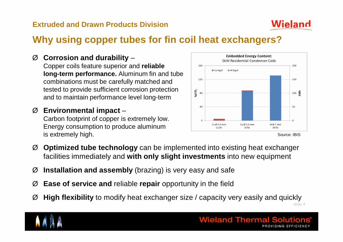
Why using copper tubes for fin coil heat exchangers?
Ø Corrosion and durability –Copper coils feature superior and reliable long-term performance. Aluminum fin and tube combinations must be carefully matched and tested to provide sufficient corrosion protection and to maintain performance level long-term
Ø Environmental impact –Carbon footprint of copper is extremely low.Energy consumption to produce aluminum is extremely high.
Ø Optimized tube technology can be implemented into existing heat exchanger facilities immediately and with only slight investments into new equipment
Ø Installation and assembly (brazing) is very easy and safe
Ø Ease of service and reliable repair opportunity in the field
Ø High flexibility to modify heat exchanger size / capacity very easily and quickly
Source: IBIS

Extruded and Drawn Products Division
slide 5
Why using inner-grooved copper tubes?
With inner-grooved tubes (IGT), the inside heat transfer performance can be increased considerably.
Results:
Ø Higher capacity of heat exchanger (HEX)
Ø Improved energy efficiencyØ Reduced size of heat
exchanger possible → smaller footprint→ less material costs

Extruded and Drawn Products Division
slide 6
Correlation of tube unit weight and inside surface enhancement of IGT
Ø Lower inside surface results in lower unit weightØ High performing tubes are heavier
Result: Tube type should be customized to achieve optimum unit weight at required performance level
Standard tube
Reduced weight gen. 1Reduced
weight gen. 2Low weight low perform.
High weight high perform.
Not feasible
Feasible
Feasibility limit
Smooth bore

Extruded and Drawn Products Division
slide 7
Parameters of fin patterns
h… fin heightn… number of finsα… lead angle (helical angle)β… apex angle (fin angle)
sk… bottom wall thicknessd1… outside diameter

Extruded and Drawn Products Division
slide 8
Optimized tube design for increased tube side performanceExample: Condensation of R410A in 3/8“ diameter tubes
Description Outside Diam. Bottom wall Number Lead angle Surface[inch] [inch] [inch] of fins [deg] increase increase
Plain tube - Reference 3/8 0,0118 0,0000 0 0 100% 100%Industry standard - Base line 3/8 0,0118 0,0079 60 18 120% 154%High performance config. 3/8 0,0118 0,0079 85 30 123% 192%
Fin height Unit weight
100%
>200%
>300%

Extruded and Drawn Products Division
slide 9
Optimized tube design for reduced unit weightExample cuprolite®: Light weight drop-in for 3/8“ diameter IGTs
Description Outside Diam. Bottom wall Number Lead angle Apex angle[inch] [inch] [inch] of fins [deg] [deg] increase
Plain tube - Reference 3/8 0,0118 0,0000 0 0 0 100%Industry standard - Base line 3/8 0,0118 0,0079 60 18 53 120%Light weight - cuprolite 3/8 0,0118 0,0079 50 25 25 113%
Fin height Unit weight
Ø Slimmer fin, decreased number of fins, higher lead angleØ Comparable performance levelØ Fin height unchanged → Drop-in
Result: Unit weight reduction of > 6%

Extruded and Drawn Products Division
slide 10
Reduction of bottom wall thickness
Example: 3/8“ x 0.0118“ reduced to 0.011“ bottom wall thickness
Issues to be considered when reducing the wall thickness:Ø Tools for bending & expansion may have to be replacedØ Pressure level requirements must be checked
Result: metal cost savings of ~7%
Description Outside diam. Unit weight[inch] [inch] factor
Base line 3/8 0,0118 100%Reduced wall 3/8 0,0110 93%
Bottom wall

Extruded and Drawn Products Division
slide 11
Miniaturization: Decreased outside diameter
Example: Optimization of 5.7 ton condenser implementing microgroove technology
Ø Cuts metal costs nearly into halfØ Improves energy efficiencyØ Significantly reduces heat exchanger weightØ Maintains all advantages of copper tube based heat exchangersØ Reduces refrigerant charge by >50%
Description Outside Required Material Refrigerantdiameter [inch] decrease tube length ratio charge
Base line 3/8'' 0,0118 100% 280 ft 100% 100%microgroove 5 mm 0,0083 36% 420 ft 54% 44%
Bottom wall Unit weight

Extruded and Drawn Products Division
slide 12
Air-cooled condenserCapacity 20 KW
Equal frontal areaEqual fans
100 85
60
80
100
Refri
gera
nt C
harg
e [%
]
micro channel microgroove® 5mm
IGT Outside Diameter
Influence of Tube Outside Diameter on Refrigerant Charge
- 15 %
microgroove® - Refrigerant Charge

Extruded and Drawn Products Division
slide 13
Development of IGT on customer demand
Example: Development task: Design optimized microgroove fin patternfor condensation of R410A
0
500
1000
1500
2000
2500
0 100000 200000 300000 400000 500000 600000 700000 800000
mass flow rate [lb/ft²hr]
heat
tran
sfer
coe
ffici
ent [
Btu
/ft²h
rF]
Standard microgroove
Wieland Design
Smooth Bore Tube
Condensation - 0,197 inch tubesR410A (no oil), T''=95°Fsubcooling 3.6°F, inlet superheat ~9°Ftube length 6.56 ft
Heat transfer performance
15.02.2011
0
0,5
1
1,5
2
2,5
0 100000 200000 300000 400000 500000 600000 700000 800000
mass flow rate [lb/ft²hr]
pres
sure
dro
p [p
si]
Condensation - 0,197 inch tubesR410A (no oil), T''=95°Fsubcooling 3.6°F, inlet superheat ~9°Ftube length 6.56 ft
Pressure drop
Significant heat transfer enhancement in condensation mode was achieved.

Extruded and Drawn Products Division
slide 14
Development of IGT on customer demand
Example: Development task: Design optimized microgroove fin patternfor condensation of R410A
Moderate enhancement for evaporation compared to standard microgroove, as this design favors condensation.

Extruded and Drawn Products Division
slide 15
Überschrift
Thank you for your attention!
For questions: [email protected]


