8
Optimizing Reactive Compensation for Wind Farms: Meeting Today's Utility and Regulatory Requirements A White Paper by American Superconductor Corporation
Optimizing Reactive Compensation for Wind Farms: Meeting Today's Utility
and Regulatory RequirementsA White Paper by American Superconductor Corporation
2
How Dynamic VAR Technology Enables Wind Farmsto Meet Grid Interconnection Requirements
Executive Summary
Wind energy is one of thefastest-growing sourcesof electricity in the
United States and around the world.The growing importance of windpower has subjected it to greaterscrutiny and more rigorousoperational standards than everbefore. As wind-generated powertransitions from boutique status to afull-fledged power source, it hasbecome apparent that the industryneeds smarter and more appropriatesolutions to address common voltage regulation and dynamic voltage stability-related interconnec-tion requirements.
Advances in dynamic voltampere reactive (VAR) technology,coupled with innovative applicationsand services, eliminate the draw-backs of traditional voltage andpower factor control methods andenable wind developers to meettoday’s more stringent and specificinterconnection requirements. Thiswhite paper explores the background issues, available solution alternatives, including the installation of a dynam-ic reactive compensation system manufactured by AmericanSuperconductor (AMSC) and operational considerations foraddressing voltage and power factor control in the contextof a wind farm and its interconnection to the grid.
Historically, wind farm operators have employedmechanically-switched capacitor banks to regulate voltageat the point of utility interconnection. However, due to itshighly and continuously variable nature, wind-dependenttechnology is poorly served by this traditional approach.There are two reasons for this. First, wind turbines, especially many of the induction type, can draw largeamounts of reactive power (VARs) from the grid. This dependency triggers frequent remedial action to maintain voltage levels within the tolerances established byregulatory requirements. Although wind energy is variable,capacitors are able to switch only fixed amounts of VARs,
and furthermore once they havebeen switched off they must wait five minutes until they can be re-energized in order to allow theirtrapped charge to dissipate.Accordingly, it is often difficult to maintain optimum amounts of reactive compensation for any length of time using switchedcapacitor banks alone. Second, insome instances, switching banks of capacitors to regulate voltage levels has been reported to causeexcess stress on the wind turbinegearboxes.
Capacitor banks typically offerthe lowest first-cost option for thecontrol of voltage on a scheduledbasis, and will undoubtedly remaina central element of almost everywind farm reactive compensationsystem. However, wind farm
interconnection requirements oftencan not be satisfied with capacitorbanks alone. Optimizing reactivecompensation for wind farms merits
a wider perspective that addresses the physical interconnec-tion with utility grids, specific interconnection regulatoryrequirements, the business relationship with the utility itself,and the cost of operation and ownership of wind farmequipment. In extreme cases, especially in weaker areas ofthe grid, deficient interconnection schemes can even affect awind farm’s megawatt output and jeopardize revenues byforcing wind farms off-line. In this broader context, it is very important to design the reactive compensation system after careful analysis of the grid dynamics at thepoint of interconnection.
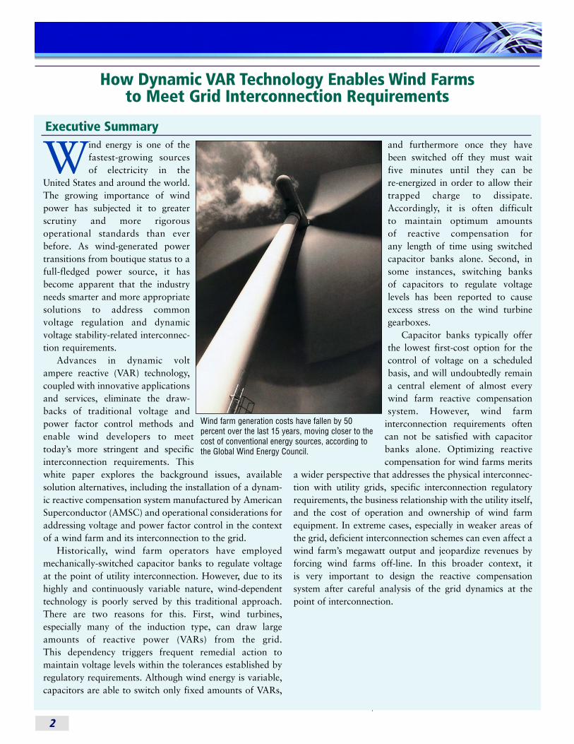
Wind farm generation costs have fallen by 50 percent over the last 15 years, moving closer to thecost of conventional energy sources, according tothe Global Wind Energy Council.
3
Executive Overview of Voltage and PowerFactor Control
This overview section discusses basicbackground information and issues, and is intended to provide the frame-work for understanding the problemsthat Dynamic VAR technology canresolve and the extended benefits that it provides.
What Are VARs?
Power consists of two components:real power and reactive power. Realpower, which is the functional elementthat can do work (driving machines,lighting lights, etc.) exists when the volt-age and the current are in phase witheach other. Reactive power, on the otherhand, exists when the voltage and thecurrent are out of phase by 90 degrees.Although reactive power is unable toprovide actual working benefit, it isoften used to adjust voltage; so it’s a useful tool for maintaining desiredvoltage levels. Every AC transmission system always has a reactive compo-nent, which can be expressed as “powerfactor.” If the power factor is low andinductive (due to the wind turbine orother electrical equipment), then VARsare being drawn off of the grid, whichreduces the system voltage. If the powerfactor is capacitive, then VARs are beingadded to the grid, which raises the system voltage. Some method is neededto manage power factor by injecting orabsorbing VARs as necessary in order tomaintain optimum voltage levels andoptimize real power flow.
How is Voltage CommonlyControlled?
Traditionally, the easiest and least-cost way to manage VARs is to installshunt capacitor or reactor banks on the transmission system.Calculations determine how manyVARs are needed at any given point, and appropriately sized banks
of capacitors are strategically placed(usually rated in MegaVARs; 5 MegaVARs or 10 MegaVARs, forexample). As voltage levels fluctuate,capacitor banks are switched on or offto either inject more VARs into the system or remove them, as required. Theeffect is that the system voltage is main-tained within tolerances established by the transmission owner as well as regulatory requirements.
Capacitor Bank SwitchingStresses Wind FarmEquipment
Although a cheap way of compensat-ing for VAR losses, capacitor bankswitching also results in an immediate,abrupt step-change in the voltage on thegrid or the bus to which they are con-nected. The step-change instantaneouslyincreases the torque, or twisting force,on a wind turbine gearbox. The variablenature of wind generation itself oftentriggers an extremely high number ofthe switching events that in some casescan begin to affect the reliability of thegearboxes. Like all induction motors,many induction-type wind turbinesdraw VARs off of the grid in amountsthat fluctuate with changes in windspeed at the turbines. This, in turn, cancause an unacceptably large voltagedrop at or near the wind farm intercon-nection point with the grid. So, giventhat these VARs need to be compensated in order to maintain voltage, it is not uncommon for a large
site to experience fifty to a hundredswitching events a day. In some cases the resulting gearbox stresses eventuallytake a toll, accelerating maintenancecycles of the gearbox.
Remote LocationsComplicate the Issue
The size of capacitor banks that canbe used is governed by the strength ofthe grid or bus. Conventionally, the sizeof step-change in voltage from a switch-ing event must be kept below a certainpercentage of total voltage (typicallytwo percent or below). A step change involtage of any larger magnitude canpotentially cause problems with otherequipment in the substation at the windfarm. While first cost considerationsmay drive a preference for solutionsemploying fewer and larger capacitorbanks, local conditions often require theuse of a series of smaller banks relativeto the strength of the grid at that location. Given that most wind farmsare located in remote areas, the typicalgrid to which they connect is quite often relatively weak at that point becausethese grids are isolated from the genera-tion sources.
The Business Side of Voltage and Power Factor Control
The party responsible for regulatingthe voltage at the wind farm is typicallythe wind farm owner. With the increas-ing prevalence of wind generation inrecent years, the issue of grid connectionrequirements for wind farms has comeunder heightened scrutiny by regulatorsas well as regional transmission organi-zations and reliability councils. As aresult of new rules such as those issuedby the Federal Energy RegulatoryCommission, wind farm owners in theUnited States are responsible for comply-ing with more stringent and specificrequirements related to voltage controland high or low voltage ride-through(the ability of the wind turbines to stay
“Wind energy has nowreached the milestone of 50GWof worldwide installed capacityand the industry is ready for a
broader roll out. Wind energy hasthe maturity, clout and
global muscle to deliver deep cutsin CO2, while providing a hedge
against fluctuating fossil fuelprices and reducing energy import
dependence.”
Arthouros ZervosChairman, Global Wind Energy Council
September 2005
4
connected to the grid during voltage disturbances) for their wind farm thanwas the case in the early years of theemerging wind power industry. Thatresponsibility is, in turn, driving windfarm owners and turbine manufacturersto incorporate dynamic VAR technologyinto their projects to enable compliancewith these standards.
Regardless of who is responsible, all the parties have a vested interest ineffectively and economically meeting thegrid connection requirements. The ultimate objective, of course, is to ensurethat wind farms provide a consistent,dependable source of real power genera-tion while operating at peak efficiency anduptime with manageable cost of owner-ship. But also important to the utility is thepower quality and reliability delivered totheir other customers on the grid.
D-VAR® Systems: An IdealStrategy for Wind FarmApplications
In recent years, AMSC’s D-VARtechnology has become a preferred andinnovative solution to address grid interconnection requirements associatedwith wind farms. In addition to address-ing grid connection requirements, the D-VAR system provides additional operational benefits such as mitigatingstep-voltage changes. It does this byusing advanced power electronics, oftenin combination with traditional capaci-tor banks, to dynamically inject orabsorb precise amounts of VARs intothe system. Where capacitor bankswitching alone is a binary on-offaction, dynamic voltage control is moreakin to a radio volume control withfluid, continuously adjustable levels.
D-VAR technology offers an economic strategy for complying withinterconnection requirements that alsocan act as a two-way shock absorber,not only resolving VAR demand and/orvoltage control issues created by thewind farm, but also enhancing the ability of sensitive wind turbine generators to avoid tripping off-line due
to common voltage disturbances thatoccur on the transmission grid. Keepingwind turbine generators on-line hasproven to be, in some locations, a signif-icant problem with today’s wind farms,and dynamic VAR technology is oftenworth the investment for this reasonalone.
For wind farm owners, the D-VAR solution delivers several significant sidebenefits beyond ensuring compliancewith standards. The elimination of switching-related stress on the gearboxes in some cases reduces maintenance requirements and extendsthe life of the equipment. Furthermore,because sudden voltage disturbances onthe collector bus are mitigated, by usingthis solution, the wind farm has enhanced ability to ride throughtransient high or low voltage conditions.This maximizes the megawatt outputand increases revenues.
For utilities, the D-VAR system eliminates large VAR demands and theresulting voltage swings caused byuncompensated wind farm operation.With this system in place, the wind farmlooks to the utility much more like a
conventional synchronous generator, in terms of the ability to dynamicallycontrol voltage. This mitigates or elimi-nates the need to install capacitor bankson the transmission system to controlvoltage. In cases where capacitor banksare called for, solutions may involve asmaller number of units with larger ratings — leading to lower costs for theutility with the added ability of the D-VAR system to offset these larger stepvoltage changes and smoothly switchcapacitor banks.
With its integral control system, thepatented D-VAR system can be custom-fitted to specific wind farm facilities. For example, a small (8 MVA) D-VARdevice can be combined with a numberof low-cost, medium-voltage capacitorbanks to create an integrated, effectivevoltage and power factor control systemfor a wind farm.
AMSC has also developed DVC™
(Dynamic VAR Compensator) solutionsand SuperVAR® machines that can address similar issues as the D-VAR system. DVC systems have been developed to address the need for large-scale solutions requiring
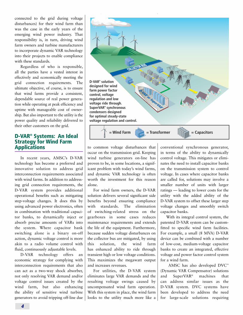
= Capacitors= Transformer = Wind Farm
D-VAR® solution designed for wind farm power factor control, voltage regulation and low voltage ride through. SuperVAR® synchronous condensers designed for optimal steady-state voltage regulation and control.
D-VAR ® or SuperVAR ®
5
hundreds of megaVARs (MVARs) ofreactive compensation connected directly to the transmission grid.AMSC’s DVC solutions are based on thewidely successful D-VAR platform.They are a hybrid STATCOM/SVC solution that utilizes inverter-basedFACTs (Flexible AC TransmissionSystems) technology similar to D-VARsystems along with proprietary fast-switched capacitors and reactors.
SuperVAR machines use standardsynchronous condenser frames and stator coils paired with advanced power-dense rotor coils made from AMSC’ssuperconductor wire. The result is a synchronous condenser that is more efficient than conventional rotatingmachines — without the high rotormaintenance costs typical of older, conventional synchronous condensers.
SuperVAR machines are specificallydesigned for continuous, steady-statedynamic VAR support, with lowerstandby losses, higher output, andgreater reliability than conventional synchronous condensers.
SuperVAR machines are cost- effective solutions that can provide tight voltage regulation and power factor correction to alleviate fluctuating volt-age and VAR demands at wind farms.
How D-VAR Systems Work
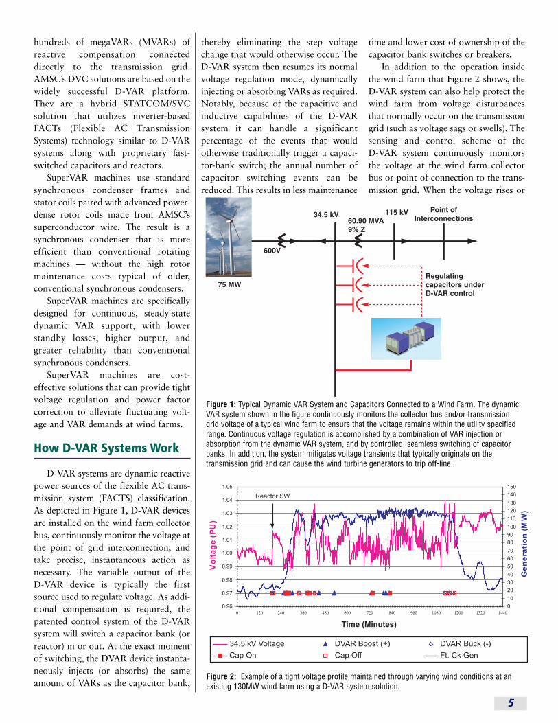
D-VAR systems are dynamic reactivepower sources of the flexible AC trans-mission system (FACTS) classification.As depicted in Figure 1, D-VAR devicesare installed on the wind farm collectorbus, continuously monitor the voltage atthe point of grid interconnection, andtake precise, instantaneous action asnecessary. The variable output of the D-VAR device is typically the firstsource used to regulate voltage. As addi-tional compensation is required, thepatented control system of the D-VARsystem will switch a capacitor bank (orreactor) in or out. At the exact momentof switching, the DVAR device instanta-neously injects (or absorbs) the sameamount of VARs as the capacitor bank,
thereby eliminating the step voltagechange that would otherwise occur. TheD-VAR system then resumes its normalvoltage regulation mode, dynamicallyinjecting or absorbing VARs as required.Notably, because of the capacitive andinductive capabilities of the D-VAR system it can handle a significant percentage of the events that would otherwise traditionally trigger a capaci-tor-bank switch; the annual number ofcapacitor switching events can bereduced. This results in less maintenance
time and lower cost of ownership of thecapacitor bank switches or breakers.
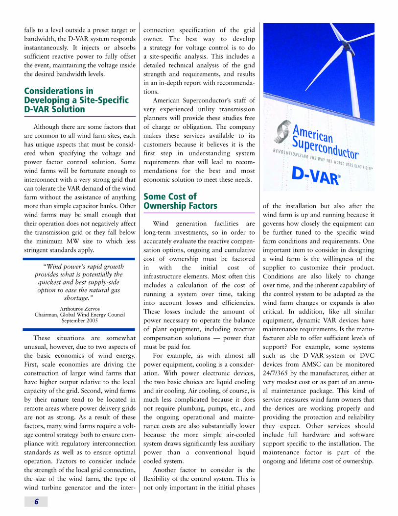
In addition to the operation insidethe wind farm that Figure 2 shows, theD-VAR system can also help protect thewind farm from voltage disturbancesthat normally occur on the transmissiongrid (such as voltage sags or swells). Thesensing and control scheme of the D-VAR system continuously monitorsthe voltage at the wind farm collectorbus or point of connection to the trans-mission grid. When the voltage rises or
Figure 2: Example of a tight voltage profile maintained through varying wind conditions at anexisting 130MW wind farm using a D-VAR system solution.
Figure 1: Typical Dynamic VAR System and Capacitors Connected to a Wind Farm. The dynamicVAR system shown in the figure continuously monitors the collector bus and/or transmissiongrid voltage of a typical wind farm to ensure that the voltage remains within the utility specifiedrange. Continuous voltage regulation is accomplished by a combination of VAR injection orabsorption from the dynamic VAR system, and by controlled, seamless switching of capacitorbanks. In addition, the system mitigates voltage transients that typically originate on the transmission grid and can cause the wind turbine generators to trip off-line.
6
falls to a level outside a preset target orbandwidth, the D-VAR system respondsinstantaneously. It injects or absorbs sufficient reactive power to fully offsetthe event, maintaining the voltage insidethe desired bandwidth levels.
Considerations inDeveloping a Site-SpecificD-VAR Solution
Although there are some factors thatare common to all wind farm sites, eachhas unique aspects that must be consid-ered when specifying the voltage andpower factor control solution. Somewind farms will be fortunate enough tointerconnect with a very strong grid thatcan tolerate the VAR demand of the windfarm without the assistance of anythingmore than simple capacitor banks. Otherwind farms may be small enough thattheir operation does not negatively affectthe transmission grid or they fall belowthe minimum MW size to which lessstringent standards apply.
These situations are somewhatunusual, however, due to two aspects ofthe basic economics of wind energy.First, scale economies are driving theconstruction of larger wind farms thathave higher output relative to the localcapacity of the grid. Second, wind farmsby their nature tend to be located inremote areas where power delivery gridsare not as strong. As a result of thesefactors, many wind farms require a volt-age control strategy both to ensure com-pliance with regulatory interconnectionstandards as well as to ensure optimaloperation. Factors to consider includethe strength of the local grid connection,the size of the wind farm, the type ofwind turbine generator and the inter-
connection specification of the gridowner. The best way to develop a strategy for voltage control is to do a site-specific analysis. This includes adetailed technical analysis of the gridstrength and requirements, and resultsin an in-depth report with recommenda-tions.
American Superconductor’s staff ofvery experienced utility transmissionplanners will provide these studies freeof charge or obligation. The companymakes these services available to its customers because it believes it is thefirst step in understanding systemrequirements that will lead to recom-mendations for the best and most economic solution to meet these needs.
Some Cost of Ownership Factors
Wind generation facilities are long-term investments, so in order toaccurately evaluate the reactive compen-sation options, ongoing and cumulativecost of ownership must be factored in with the initial cost of infrastructure elements. Most often thisincludes a calculation of the cost of running a system over time, taking into account losses and efficiencies.These losses include the amount ofpower necessary to operate the balanceof plant equipment, including reactivecompensation solutions — power thatmust be paid for.
For example, as with almost allpower equipment, cooling is a consider-ation. With power electronic devices,the two basic choices are liquid coolingand air cooling. Air cooling, of course, ismuch less complicated because it doesnot require plumbing, pumps, etc., andthe ongoing operational and mainte-nance costs are also substantially lowerbecause the more simple air-cooled system draws significantly less auxiliarypower than a conventional liquid cooled system.
Another factor to consider is theflexibility of the control system. This isnot only important in the initial phases
of the installation but also after thewind farm is up and running because itgoverns how closely the equipment canbe further tuned to the specific windfarm conditions and requirements. Oneimportant item to consider in designinga wind farm is the willingness of thesupplier to customize their product.Conditions are also likely to changeover time, and the inherent capability ofthe control system to be adapted as thewind farm changes or expands is alsocritical. In addition, like all similarequipment, dynamic VAR devices havemaintenance requirements. Is the manu-facturer able to offer sufficient levels ofsupport? For example, some systemssuch as the D-VAR system or DVCdevices from AMSC can be monitored24/7/365 by the manufacturer, either atvery modest cost or as part of an annu-al maintenance package. This kind of service reassures wind farm owners thatthe devices are working properly andproviding the protection and reliabilitythey expect. Other services shouldinclude full hardware and software support specific to the installation. Themaintenance factor is part of the ongoing and lifetime cost of ownership.
“Wind power's rapid growthprovides what is potentially thequickest and best supply-sideoption to ease the natural gas
shortage.”
Arthouros ZervosChairman, Global Wind Energy Council
September 2005
7
Summary
It is very commonplace for today’sgeneration of wind farms – larger-scaleoperations located in remote areas of thegrid – to require more sophisticatedvoltage control strategies than theirearly predecessors. Wind farms also can have unique circumstances andoperational considerations that warrantevaluation of the merits of traditional“voltage control by capacitor banks”approach. Employing dynamic VARdevices, sometimes in combination with control of capacitor banks, eliminates many of the negative consequences of traditional solutions.Both the wind farm developer/ownerand ultimately the utility benefit fromthis approach.
The D-VAR system advantages for the wind farm include:• Grid interconnection standards
are met.
• Voltage sags or swells originatingfrom the transmission grid are mitigated. This enhances the abilityof the wind farm to stay online andhelps to prevent nuisance tripping of the wind turbine generators. This also helps maximize the poweroutput of the wind farm which leads to increased revenues.
• Step-voltage changes due to local or remote capacitor-bank switchingare mitigated, or eliminated, thuspreventing excess gearbox stress or failure.
• Capacitor-bank switching events are minimized, which reduces switch maintenance costs.
•Overall grid interconnection costsare minimized.
The D-VAR system advantages for the utility:• Large VAR demands are eliminated,
as are the resulting voltage swingscaused by uncompensated wind farmoperation. The wind farm maintainsa consistent, smooth voltage profile.
• In some cases, the need to installadditional capacitor banks on thetransmission system is eliminated.
• If transmission capacitor banks areinstalled for any reason, their impactto the local wind farm is minimized.
About AmericanSuperconductorCorporation
American Superconductor (AMSC)is the manufacturer of the D-VAR andDVC dynamic reactive compensationsystems which provide voltage supportto utility transmission and distributionsystems. In addition to wind farms,AMSC D-VAR systems are also beingused worldwide to address a variety ofgrid-related problems such as voltageinstability, power transfer constraintsand steady-state voltage regulation.
AMSC is the world’s principal vendor of high temperature supercon-ductor (HTS) wire and large rotatingsuperconductor machinery, and it is aworld leading supplier of dynamic reactive power grid stabilization products. AMSC's HTS wire and powerelectronic converters are at the core of abroad range of new electricity transmis-sion and distribution, transportation,medical and industrial processing applications, including dynamic reactivepower grid stabilization solutions, largeship propulsion motors and generators,smart, controllable, superconductorpower cables and advanced defense systems. The company’s products aresupported by hundreds of patents and licenses covering technologies fundamental to Revolutionizing the Way the World Uses Electricity™. More information is available at http://www.amsuper.com.
American Superconductor anddesign, AMSC, POWERED BY AMSC,Revolutionizing the Way the World UsesElectricity and DVC are trademarks and D-VAR and SuperVAR are registered trademarks of AmericanSuperconductor Corporation. All othertrademarks are the property of theirrespective owners.
© 2006 American Superconductor Corporation
For more information, please contact:American Superconductor
Two Technology DriveWestborough, MA 01581
toll-free USA/Canada: +1 800 315 3319tel +1 978 842 3362fax +1 978 842 [email protected]
© 2006 American Superconductor Corporation. All rights reserved. Printed in USA.American Superconductor and design, AMSC and Revolutionizing the Way the World Uses Electricity are trademarks of American Superconductor.
All other trademarks are either property of American Superconductor or property of their respective owners.
WF_WP_0306


