12
PDP Series Positive displacement dosing pump The right dosing choice

PDP SeriesPositive displacement dosing pump
The right dosing choice

PDP SeriesMAIN ELEMENTS TO SUPPORT OUR PRODUCTS
VersatilityDifferent piston sizes are available to suit each application, starting from 1,3 until 4,000 l/h.
ReliabilityThe high degree of accuracy and reproducibility with high quality materials selection make the piston pump series PDP to assure the maximum reliability.
QualityAppropriate materials are selected for each application.
Positive displacement plunger dosing pump
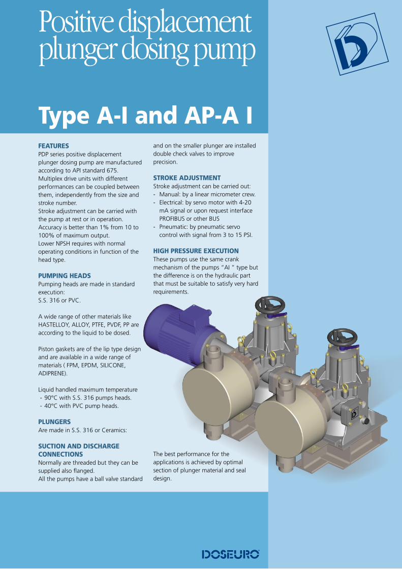
FEATURESPDP series positive displacement plunger dosing pump are manufactured according to API standard 675.Multiplex drive units with different performances can be coupled between them, independently from the size and stroke number.Stroke adjustment can be carried with the pump at rest or in operation.Accuracy is better than 1% from 10 to 100% of maximum output.Lower NPSH requires with normal operating conditions in function of the head type.
PUMPING HEADSPumping heads are made in standard execution:S.S. 316 or PVC.
A wide range of other materials like HASTELLOY, ALLOY, PTFE, PVDF, PP are according to the liquid to be dosed.
Piston gaskets are of the lip type design and are available in a wide range of materials ( FPM, EPDM, SILICONE, ADIPRENE).
Liquid handled maximum temperature�- 90°C with S.S. 316 pumps heads.�- 40°C with PVC pump heads.
PLUNGERSAre made in S.S. 316 or Ceramics:
SUCTION AND DISCHARGE CONNECTIONSNormally are threaded but they can be supplied also flanged.All the pumps have a ball valve standard
and on the smaller plunger are installed double check valves to improve precision.
STROKE ADJUSTMENTStroke adjustment can be carried out:- Manual: by a linear micrometer crew.- Electrical: by servo motor with 4-20
mA signal or upon request interface PROFIBUS or other BUS
- Pneumatic: by pneumatic servo control with signal from 3 to 15 PSI.
HIGH PRESSURE EXECUTIONThese pumps use the same crank mechanism of the pumps “AI ” type but the difference is on the hydraulic part that must be suitable to satisfy very hard requirements.
The best performance for the applications is achieved by optimal section of plunger material and seal design.
Type A-I and AP-A I
PDP Series
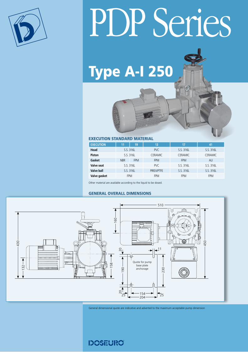
General dimensional quote are indicative and adverted to the maximum acceptable pump dimension
GENERAL OVERALL DIMENSIONS
Type A-I 250
EXECUTION STANDARD MATERIAL EXECUTION 11 19 13 17 41
Head S.S. 316L PVC S.S. 316L S.S. 316L
Piston S.S. 316L CERAMIC CERAMIC CERAMIC
Gasket NBR FPM FPM FPM AU
Valve seat S.S. 316L PVC S.S. 316L S.S. 316L
Valve ball S.S. 316L PIREX/PTFE S.S. 316L S.S. 316L
Valve gasket FPM FPM FPM FPM Other material are available according to the liquid to be dosed.
510
132
430
158
160
450
Quote for pump base plate anchorage
190
25
2020
230
25204
11
154
Pump type
Reducer ratio Capacity Max Press. Kg/cm2 ConnectionsPiston Diam.
SPM L/1’ L/h SS316 PVC Threaded Flanged
(*1) 50 Hz 60 Hz 50 Hz 60 Hz 50 Hz 60 Hz 0,55kw 0,75kw 1,1kw 0,55kw 0,75kw 1,1kw ø G.m. UNI ANSI ø mm
A-I 250 - 6
I 35 42 0,02 0,024 1,2 1,44
40 / / / / 10 / / / / 1 / 2 “ 15 1 / 2 “ 6F 60 72 0,03 0,040 2 2,4
C 96 116 0,05 0,064 3,2 3,8
B 120 0,07 0,080 4 4,8
A-I 250 - 11
F 60 72 0,12 0,140 7 8,4
40 / / / / 10 / / / / 1 / 2 “ 15 1 / 2 “ 11.11C 96 116 0,19 0,224 11,2 13,4
B 120 0,23 0,280 14 16,8
A-I 250 - 18
F 60 72 0,31 0,366 18,3 22,0
40 / / / / 10 / / / / 1 / 2 “ 15 1 / 2 “ 17.46C 96 116 0,49 0,586 29,3 35,2
B 120 0,61 0,732 36,6 43,9
A-I 250 - 25
F 60 72 0,68 0,820 41 49,2
40 / / / / 10 / / / / 1 / 2 “ 15 1 / 2 “ 25.4C 96 116 1,10 1,314 65,7 78,8
B 120 1,37 1,640 82 98,4
A-I 250 - 30
F 60 72 1,02 1,220 61 73,2
40 / / / / 10 / / / / 1 / 2 “ 15 1 / 2 “ 30,16C 96 116 1,63 1,960 98 117,6
B 120 2,03 2,440 122 146,4
A-I 250 - 38
F 60 72 1,62 1,940 97 116,4
26 36 40 10 / / / / 1 / 2 “ 15 1 / 2 “ 38,1C 96 116 2,60 3,120 156 187,2
B 120 3,23 3,880 194 232,8
A-I 250 - 47
F 60 72 2,53 3,040 152 182,4
17 23 28 10 / / / / 3 / 4 “ 20 3 / 4 “ 47,63C 96 116 4,07 4,880 244 292,8
B 120 5,07 6,080 304 364,8
A-I 250 - 54
F 60 72 3,27 3,920 196 235,2
13 18 22 10 / / / / 3 / 4 “ 20 3 / 4 “ 53,98C 96 116 5,22 6,260 313 375,6
B 120 6,53 7,840 392 470,4
A-I 250 - 64
F 60 72 4,52 5,420 271 325,2
9,5 13 16 9,5 10 / / 1 “ 25 1 “ 63,5C 96 116 7,22 8,660 433 519,6
B 120 9,03 10,840 542 650,4
A-I 250 - 76
F 60 72 6,50 7,800 390 468,0
6,6 9 11 6,6 9 10 1 “ 25 1 “ 76,2C 96 116 10,40 12,480 624 748,8
B 120 13,00 15,600 780 936,0
A-I 250 - 89
F 60 72 8,85 10,620 531 637,2
4,8 6,6 8 4,8 6,6 8 1 “ 25 1 “ 88,9C 96 116 14,17 17,000 850 1020,0
B 120 17,70 21,240 1062 1274,4
A-I 250 - 98
F 60 72 10,85 13,020 651 781,2
3,9 5,4 6,6 3,9 5,4 6,6 1 -1 / 2 “ 40 1 -1 / 2 “ 98,43C 96 116 17,35 20,820 1041 1249,2
B 120 21,70 26,040 1302 1562,4
A-I 250 - 108F 60 72 13,03 15,640 782 938,4
3,6 5,2 / / 3,6 5,2 / / 1 -1 / 2 “ 40 1 -1 / 2 “ 107,95C 96 116 20,87 25,040 1252 1502,4
A-I 250 - 120F 60 72 17,00 20,400 1020 1224,0
3,3 4,4 / / 3,3 4,4 / / 1 -1 / 2 “ 40 1 -1 / 2 “ 120,65C 96 116 27,42 32,900 1645 1974,0
Positive displacement plunger dosing pump
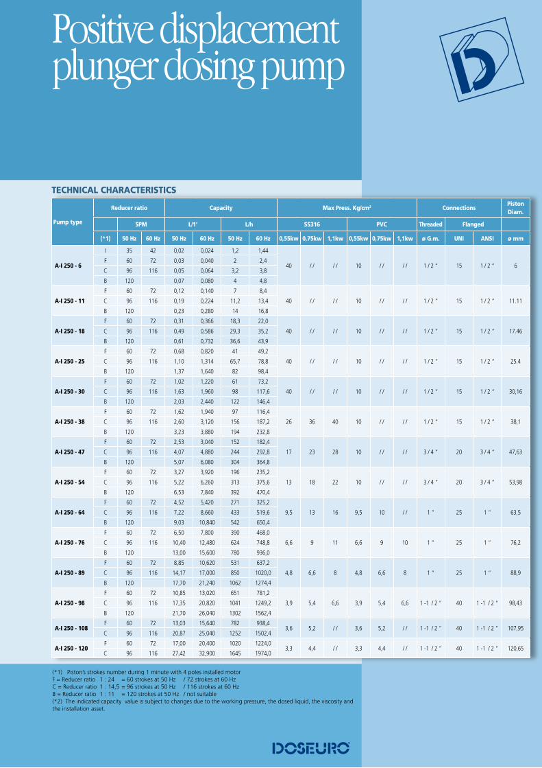
TECHNICAL CHARACTERISTICS
(*1) Piston’s strokes number during 1 minute with 4 poles installed motor F = Reducer ratio 1 : 24 = 60 strokes at 50 Hz / 72 strokes at 60 HzC = Reducer ratio 1 : 14,5 = 96 strokes at 50 Hz / 116 strokes at 60 HzB = Reducer ratio 1 : 11 = 120 strokes at 50 Hz / not suitable (*2) The indicated capacity value is subject to changes due to the working pressure, the dosed liquid, the viscosity and the installation asset.

PDP Series
General dimensional quote are indicative and adverted to the maximum acceptable pump dimension
Type A-I 350
EXECUTION STANDARD MATERIAL EXECUTION 11 19 13 17 41
Head S.S. 316L PVC S.S. 316L S.S. 316L
Piston S.S. 316L CERAMIC CERAMIC CERAMIC
Gasket NBR FPM FPM FPM AU
Valve seat S.S. 316L PVC S.S. 316L S.S. 316L
Valve ball S.S. 316L PIREX/PTFE S.S. 316L S.S. 316L
Valve gasket FPM FPM FPM FPM Other material are available according to the liquid to be dosed.
GENERAL OVERALL DIMENSIONS
Quote for pump base plate anchorage
235
30
2525
285
30250
13
190
690
232
570
158
160
550
Positive displacement plunger dosing pump
Pump type
Reducer ratio Capacity Max Press. Kg/cm2 ConnectionsPiston Diam.
SPM L/1’ L/h SS316 PVC Threaded Flanged
(*1) 50 Hz 60 Hz 50 Hz 60 Hz 50 Hz 60 Hz 1,1 Kw 1,5 Kw 2,2 Kw 3 Kw 1,1 Kw 1,5 Kw 2,2 Kw ø G.m. UNI ANSI ø mm
A-I 350 - 25
F 60 72 0,96 1,150 57,5 69,0
40 / / / / / / 10 / / / / 1 / 2 “ 15 1 / 2 “ 25,4C 96 116 1,53 1,840 92 110,4
B 120 1,92 2,300 115 138,0
A-I 350 - 30
F 60 72 1,42 1,700 85 102,0
40 / / / / / / 10 / / / / 1 / 2 “ 15 1 / 2 “ 30,16C 96 116 2,28 2,740 137 164,4
B 120 2,83 3,400 170 204,0
A-I 350 - 38
F 60 72 2,27 2,720 136 163,2
37,5 40 / / / / 10 / / / / 3 / 4” 20 3 / 4” 38,1C 96 116 3,63 4,360 218 261,6
B 120 4,53 5,440 272 326,4
A-I 350 - 47
F 60 72 3,55 4,260 213 255,6
24 32,8 40 / / 10 / / / / 3 / 4” 20 3 / 4” 47,63C 96 116 5,68 6,820 341 409,2
B 120 7,10 8,520 426 511,2
A-I 350 - 54
F 60 72 4,57 5,480 274 328,8
18,7 25,5 37,5 40 10 / / / / 1” 25 1” 53,98C 96 116 7,30 8,760 438 525,6
B 120 9,13 10,960 548 657,6
A-I 350 - 64
F 60 72 6,32 7,580 379 454,8
13,5 18,5 27 31,6 10 / / / / 1” 25 1” 63,5C 96 116 10,10 12,120 606 727,2
B 120 12,63 15,160 758 909,6
A-I 350 - 76
F 60 72 9,10 10,920 546 655,2
9,4 12,8 18,8 22 9,4 10 / / 1” 25 1” 76,2C 96 116 14,55 17,460 873 1047,6
B 120 18,20 21,840 1092 1310,4
A-I 350 - 89
F 60 72 12,38 14,860 743 891,6
6,9 9,4 13,8 16 6,9 9,4 10 1- 1/2 “ 40 1- 1/2 “ 88,9C 96 116 19,82 23,780 1189 1426,8
B 120 24,77 29,720 1486 1783,2
A-I 350 - 98
F 60 72 15,18 18,220 911 1093,2
5,6 7,7 11,3 13 5,6 7,7 10 1- 1/2 “ 40 1- 1/2 “ 98,43C 96 116 24,28 29,140 1457 1748,4
B 120 30,37 36,440 1822 2186,4
A-I 350 - 108F 60 72 18,25 21,900 1095 1314,0
5,1 7 10 / / 5,1 7 10 1- 1/2 “ 40 1- 1/2 “ 107,95C 96 116 29,22 35,060 1753 2103,6
A-I 350 - 120F 60 72 22,80 27,360 1368 1641,6
4,7 6,4 8,7 / / 4,7 6,4 8,7 2” 50 2” 120,65C 96 116 36,50 43,800 2190 2628,0
A-I 350 - 127F 60 72 25,27 30,320 1516 1819,2
4,2 5,8 7,9 / / 4,2 5,8 7,9 2” 50 2” 127C 96 116 40,43 48,520 2426 2911,2
A-I 350 - 140F 60 72 30,58 36,700 1835 2202,0
3,5 4,8 6,5 / / 3,5 4,8 6,5 2” 50 2” 139,7C 96 116 48,92 58,700 2935 3522,0
A-I 350 - 152F 60 72 36,40 43,680 2184 2620,8
2,9 4 5,5 / / 2,9 4 5,5 2” 50 2” 152,40C 96 116 58,23 69,880 3494 4192,8
A-I 350 - 160F 60 72 39,50 47,400 2370 2844,0
2,7 3,7 5 / / 2,7 3,7 5 2” 50 2” 158,8C 96 116 63,33 76,000 3800 4560,0
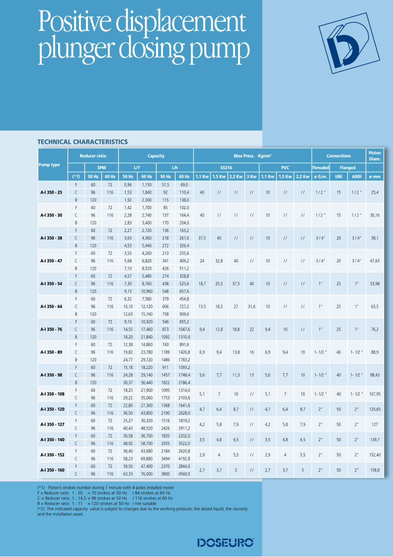
TECHNICAL CHARACTERISTICS
(*1) Piston’s strokes number during 1 minute with 4 poles installed motor F = Reducer ratio 1 : 20 = 70 strokes at 50 Hz / 84 strokes at 60 HzC = Reducer ratio 1 : 14,5 = 96 strokes at 50 Hz / 116 strokes at 60 HzB = Reducer ratio 1 : 11 = 120 strokes at 50 Hz / not suitable (*2) The indicated capacity value is subject to changes due to the working pressure, the dosed liquid, the viscosity and the installation asset.
PDP Series
(*1) Piston’s strokes number during 1 minute with 4 poles installed motor I = Reducer ratio 1 : 40 = 35 strokes at 50 Hz / 42 strokes at 60 HzF = Reducer ratio 1 : 24 = 60 strokes at 50 Hz / 72 strokes at 60 HzC = Reducer ratio 1 : 14,5 = 96 strokes at 50 Hz / 116 strokes at 60 HzB = Reducer ratio 1 : 12 =120 strokes at 50 Hz / 144 strokes at 60 Hz(*2) The indicated capacity value is subject to changes due to the working pressure, the dosed liquid, the viscosity and the installation asset.
Pump type
Reducer ratio Capacity Max Press. Kg/cm2 ConnectionsPiston Diam.
SPM L/1’ L/h S.S.316 Thread. Flanged
(*1) 50 Hz 60 Hz 50 Hz 60 Hz 50 Hz 60 Hz 0,55 Kw 0,75 Kw 1,1 Kw ø G.m. UNI ANSI ø mm
AP-A I 250 - 8
I 35 42 0,04 0,044 2,2 2,64
250 / / / / 1 / 2 “ 15 1 / 2 “ 8F 60 72 0,06 0,076 3,8 4,56
C 96 116 0,10 0,122 6,1 7,3
B 120 0,13 0,152 7,6 9,1
AP-A I 250 - 12
F 60 72 0,15 0,176 8,8 10,6
250 / / / / 1 / 2 “ 15 1 / 2 “ 12C 96 116 0,24 0,284 14,2 17,0
B 120 0,29 0,352 17,6 21,1
AP-A I 250 - 16
F 60 72 0,27 0,322 16,1 19,3
150 203 248 1 / 2 “ 15 1 / 2 “ 16C 96 116 0,43 0,516 25,8 31,0
B 120 0,54 0,644 32,2 38,6
AP-A I 250 - 22
F 60 72 0,51 0,616 30,8 37,0
79 107 131 1 / 2 “ 15 1 / 2 “ 22C 96 116 0,82 0,986 49,3 59,2
B 120 1,03 1,232 61,6 73,9
AP-A I 250 - 25
F 60 72 0,70 0,840 42 50,4
61 83 102 1 / 2 “ 15 1 / 2 “ 25C 96 116 1,12 1,340 67 80,4
B 120 1,40 1,680 84 100,8
AP-A I 250 - 30
F 60 72 1,00 1,200 60 72,0
42 58 70 3 / 4 “ 20 3 / 4 “ 30C 96 116 1,62 1,940 97 116,4
B 120 2,00 2,400 120 144,0
AP-A I 250 - 35
F 60 72 1,37 1,640 82 98,4
31 42 52 3 / 4 “ 20 3 / 4 “ 35C 96 116 2,20 2,640 132 158,4
B 120 2,73 3,280 164 196,8
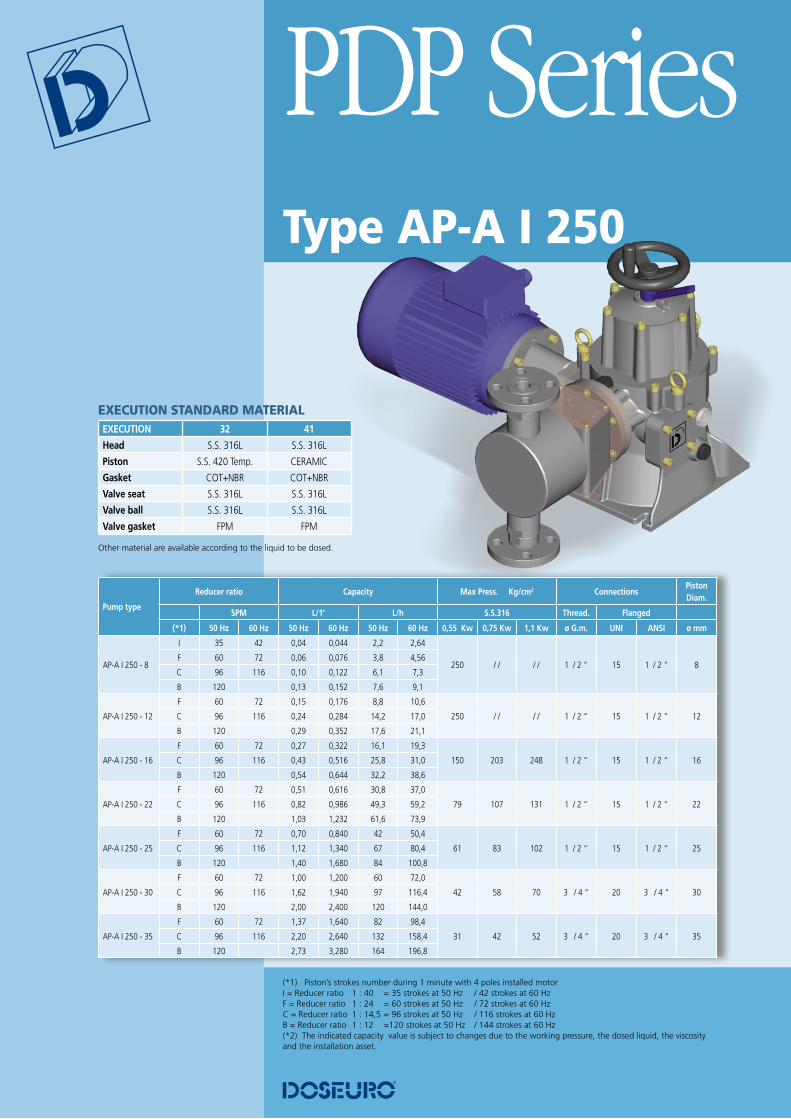
EXECUTION STANDARD MATERIAL EXECUTION 32 41
Head S.S. 316L S.S. 316L
Piston S.S. 420 Temp. CERAMIC
Gasket COT+NBR COT+NBR
Valve seat S.S. 316L S.S. 316L
Valve ball S.S. 316L S.S. 316L
Valve gasket FPM FPM
Other material are available according to the liquid to be dosed.
Type AP-A I 250

Positive displacement plunger dosing pump
(*1) Piston’s strokes number during 1 minute with 4 poles installed motor F = Reducer ratio 1 : 24 = 60 strokes at 50 Hz / 72 strokes at 60 HzC = Reducer ratio 1 : 14,5 = 96 strokes at 50 Hz / 116 strokes at 60 HzB = Reducer ratio 1 : 12 = 120 strokes at 50 Hz / 144 strokes at 60 Hz (*2) The indicated capacity value is subject to changes due to the working pressure, the dosed liquid, the viscosity and the installation asset.
Pump type
Reducer ratio Capacity Max Press. Kg/cm2 ConnectionsPiston Diam.
SPM L/1’ L/h S.S.316 Thread. Flanged
(*1) 50 Hz 60 Hz 50 Hz 60 Hz 50 Hz 60 Hz 1,1 kW 1,5 kW 2,2 kW 3 kW ø G.m. UNI ANSI ø mm
AP-A I 350 - 16
F 60 72 0,36 0,430 21,5 25,8
213 250 / / / / 1 / 2 “ 15 1 / 2 “ 16C 96 116 0,58 0,690 34,5 41,4
B 120 0,72 0,860 43 51,6
AP-A I 350 - 22
F 60 72 0,70 0,842 42,1 50,5
112 153 225 250 1 / 2 “ 15 1 / 2 “ 22C 96 116 1,12 1,348 67,4 80,9
B 120 1,41 1,686 84,3 101,2
AP-A I 350 - 25
F 60 72 0,95 1,140 57 68,4
87 119 174 204 1 / 2 “ 15 1 / 2 “ 25C 96 116 1,48 1,780 89 106,8
B 120 1,90 2,280 114 136,8
AP-A I 350 - 30
F 60 72 1,42 1,700 85 102,0
60 82 121 141 3 / 4 “ 20 3 / 4 “ 30C 96 116 2,27 2,720 136 163,2
B 120 2,83 3,400 170 204,0
AP-A I 350 - 35
F 60 72 1,92 2,300 115 138,0
45 61 89 104 3 / 4 “ 20 3 / 4 “ 35C 96 116 3,07 3,680 184 220,8
B 120 3,83 4,600 230 276,0
AP-A I 350 - 40
F 60 72 2,50 3,000 150 180,0
34 46 68 80 3 / 4 “ 20 3 / 4 “ 40C 96 116 4,00 4,800 240 288,0
B 120 5,00 6,000 300 360,0
AP-A I 350 - 50
F 60 72 3,92 4,700 235 282,0
22 30 44 51 1 “ 25 1 “ 50C 96 116 6,27 7,520 376 451,2
B 120 7,83 9,400 470 564,0
Type AP-A I 350

THE BENEFITS OF FLUID CONTROL ASSURE
- Increase efficiency and pump life.- Decrease maintenance and operating
costs.
The control of fluid dynamics is essential to ensure efficient and safe use of process systems. Uncontrolled fluid in motion can physically destroy a pumping system including the pumping, valves, meters, back pressure valves, in-line instrumentation and equipment.
1 FILTERSWe suggest to install filters (on the suction pipe) to keep back impurities that can be presented on liquid to dose or coming from pipeline system.The use of filters assures a trouble-free dosing.
2 SAFETY VALVESSafety valves are designed to protect the pump and chemical feed system from over pressure damage ‘caused by defective equipment or a blockage in the chemical feed line.
PDP SeriesCorrect installation and accessories
2 SAFETY VALVES
4 PULSATION DAMPENERS

Positive displacement plunger dosing pump
Correct installation and accessories3 BACK PRESSURE VALVESBack pressure valves apply positive discharge pressure to a metering pump system to prevent siphoning and eliminate varying down-stream pressure.
4 PULSATION DAMPENERMetering pumps have a pulsating flow.Both positive displacement pumps and quick closing valves start and stop fluids that are in motion. Positive displacement pumps derive their pumping action by capturing a given amount of fluid in a chamber and pushing it out the pump’s
discharge. Each pump cycle includes a suction stroke during which fluid flow is stopped. This pumping action produces an acceleration/deceleration of the fluid, creating units of uncontrolled energy, resulting in PULSATION, observed as pressure spikes.
Pulsation dampener is required for two reasons:
�- To reduce high, non - permissible pressure fluctuations.
�- To create a nearly continuous flow.
1 FILTERS
3 BACK PRESSURE VALVES

CN
ME0
PDPG
000G
0000
6
The right dosing choice
HEAD OFFICEVia G. Carducci 14120093 Cologno Monzese (MI) ItalyTel.: +39 02 27301324Fax: +39 02 26700883e-mail: [email protected]
DOSEURO (UK) LTD.Unit 8, East Road Industrial EstateSleaford, Lincolnshire NG34 7EHTel.: +44 1529 300045Fax: +44 1529 410967e-mail: [email protected]
Our range of production also includes:
SR series:Plunger dosing pumps “A” typesHydraulic diaphragm dosing pumps “B”, “BR” and “SD” typesMechanical diaphragm dosing pumps “D” typesMechanical diaphragm dosing pumps “FM” types
SDP series:Solenoid dosing pumps “S” typeSolenoid dosing pumps “GA” type
H series:Automatic plants for dissolution and preparation of powder polyelectrolytes “HA”, “HB” types
EM series:Electric mixers for chemical mixing “DMT”, “DEM”, “DRV” and “DRC” types


![Pioneer Pdp 434cmx Pdp 43mxe1 s [ET]](https://static.documents.pub/doc/80x56/55cf8eae550346703b948a48/pioneer-pdp-434cmx-pdp-43mxe1-s-et.jpg)


