www.kraenzle.com Original-Operating manual High-pressure cleaners Read and conform safety instructions before use! Keep instructions in a safe place for later use and pass them on to any future user. - GB - HD 7/122 HD 10/122
Transcript
www.kraenzle.com
Original-Operating manualH i g h - p r e s s u r e c l e a n e r s
Read and conform safety instructions before use!
Keep instructions in a safe place for later use and pass them on to any future user.
- GB -
HD 7/122 HD 10/122
2
Dear customerWe would like to congratulate you on your new high pressure cleaner and to thank you for the purchase.To ease your introduction to the use of the cleaner, we have provided the following pages of explanations, tips and hints, which we ask you to read before using it for the first time.The equipment will assist you professionally in all cleaning tasks, e.g.:
Description
Zulässige Abweichung der Zahlenwerte ± 5 % nach VDMA Einheitsblatt 24411
Technicaldata
Operating pressure, steplessly adjustableNozzle sizePerm. overpressureWater outputHot water input (1-8 bar)Suction heightHigh pressure hoseElectrical ratingsConnect. wattage input outputWeightDimensions in mmSound level acc.to DIN 45 635 with dirtkillerSound level LWARecoil at lance
Vibrations at lance
with dirtkiller
KränzleHD 7/122
10 - 120 bar
20 03135 barat 1400 rpm 7 l/minmax. 60 °C1.0 m10 m230V ; 50 Hz ; 7,5 AP1: 1.6 kW P2: 1.0 kW18,5 kg 300 x 330 x 80071 dB (A) 84dB (A)84 dB (A)ca. 27 N
1.9 m/s²Order n°:41.73041.730 1
*
Muß dem Gerät mindestens zugeführt werden (Siehe Seite 7)*
KränzleHD 10/122
10 - 120 bar
20 045135 barat 2800 rpm 10 l/minmax. 60 °C- -10 m230V ; 50 Hz ; 11 AP1: 2.5 kW P2: 1.8 kW18,5 kg 300 x 330 x 80071 dB (A) 91 dB (A)91 dB (A)ca. 27 N
1.9 m/s²Order n°:41.73141.731 1
- facades- flagstones- terraces
- vehicles of all types- containers- machines etc.
- removing of old paint
3
Connection principleThe KRÄNZLE HD7/122 + HD10/122 - high pressure cleaners are mobile machi-nes. The design can be seen from the diagram.
Components1 Water inlet connection with filter2 Suction hose with filter (special accessory) Order no. 15.038 33 High pressure pump4 Press. gauge with glycerin filling
5 Unloader valve - safety valve6 High pressure hose7 Spray gun8 Interchangeable lance with high pressure nozzle 9 Nonreturn valve (see page 8)
Description8 7
2
Water
6
4
5
3
1
230 V
9
4
Water- and cleaning/detergent systemWater can be connected at mains pressure to the high pressure pump or it can be sucked directly from a storage tank. The water is then forced under pressu-re by the high pressure pump to the lance. The high pressure jet is formed by the nozzle at the end of the lance.
Lance with trigger gunThe machine can only be operated when the safety trigger is squeezed. The machine can only be operated when the safety trigger is squeezed. When the lever is squeezed, the spray gun opens. The liquid is then pumped to the nozzle. The spray pressure increases and quickly reaches the selected opera-ting pressure.When the trigger is released, the trigger gun closes and any further spraying of liquid from the lance is stopped.The increase in pressure when the trigger gun is closed causes the unloader valve-safety valve to open. The pump remains switched on and continues to pump liquid through the pump at reduced pressure. When the trigger gun is opened, the unloader valve - safety valve closes and the pump ressumes pres-sure spraying from the lance.
The trigger gun is a safety device. Repairs should only be performed by qualified persons. Should replacement parts be required, use only components authorized by the manufactu-rer.
Unloader valve - safety valveThe unloader valve - safety valve protects the machine from a build p of ex-cess pressure, and is designed not to permit an excess pressure to be selec-ted for operation. The limit nut on the handle is sealed with a spray coating. *(see page 22:“Stopping leaks from the hose or gun“.) The operating pressure and spray rate can be steplessly adjusted by turning the handle.
Replacements, repairs, new adjustments and sealing should only be performed by qualified persons.
Description
5
Description
The motor is protected from overload by a motor protection switch, which automatically cuts out the motor in the event of overload. However should the switch trip frequently, the cause of the malfunction should be located and recti-fied (see page 6).
Motor protection switch
Setting up
Neither set up and operate the machine in rooms where there is a risk of fire or explosion nor put it into puddles. Do not use the machine under water.
Never use liquid containing solvents such as paint thinners, petrol, oil or similar liquid matter. Pay attention to the instructions of the manufacturers of the cleaning agents. The seals in the machine are not resistant to solvents. The spray of solvents is inflammable, explosive and poisonous.
CAUTION !
CAUTION !
When running your high pressure cleaner with hot water of 60° C raised temperatures occur. Do not touch the machine with-out safety gloves!
Replacements and inspection work should only be performed by qualified persons when the machine is disconnected from the power supply, i.e. pull out the plug from the electrical socket.
Location
6
Electrical connectionThe machine is supplied with an electrical power cable with plug.
The mains plug must be fitted to a standard grounded socket with a 30mA residual current operated device. The socket must be protected with a 16A delay action fuse on the mains side.
KRÄNZLE HD 7/122 230 Volt / 50 Hz KRÄNZLE HD 10/122 230 Volt / 50 Hz
When using an extension cable, this must have an earthed lead which is properly connected to the socket. The conductors in the extension cable must have a minimum cross section of 1.5 mm². Plug connections must be of a spray-proof design, and may not be located on a wet floor. (with extension cables of more than 10 m - 2.5 mm2 )
CAUTION !The use of extension cables which are too long may lead to malfunctions and start up difficulty.
When using a cable drum, always keep the cable wound as far as possible.
Description
230 V
7
Description
Please check that the high pressure cleaner has available the quantity of water specified on page 2 (techn. specifications) (Litres per minute).
Water connection:
Test:
Allow the water to run through the supply hose into a bucket for 1 minute.
The received quantity of water must be at least the quantity given on page 2 !!!
Lack of water causes fast wear on seals (no warranty)
8
Brief operating instructionsWhen operating your high pressure cleaner pay attention that it is in a horizontal position.1. Connect the high pressure hose with the spray gun.2. Connect to suitable water supply.3. Flush the air from the pump (open and close the spray gun several times)4. Make the electrical connection5. Switch on the machine with opened spray gun and commence cleaning.6. After completing the work, completely empty the pump (switch the motor
on for approximately 20 seconds without the suction and spray gun). - Only use clean water ! Protect from frost !
CAUTION !Please pay attention to the regulations of your waterworks company. In accord-ance with EN 61 770, the machine may not be directly connected to the public drinking water supply lines.
A brief connection however is permissible according to DVGW (German Associa-tion for Gas and Water Affairs) if a tube ventilator with check valve (Kränzle Order-No. 41.016 4) is built into the water supply.
Also indirect connection to the public drinking water supply lines is permissible by way of free emission in accordance with EN 61 770; e.g. by using a reservoir with a float valve.
Direct connection to a non-drinking water supply line is permissible.
High pressure hose and spray deviceThe high pressure hose and spraying device supplied with the machine are made of high grade material, they are also optimized for the machine and marked as required by the appropriate regulations. - Hose length max. 20 m.
If replacement parts are required, only such parts that are author-ized by the manufacturer and which bear the markings required by the appropriate regulations may be used. The high pressure hose and spray device must be connected in a pressure-tight manner (no leak). The high pressure hose may not be driven over, pulled exces-sively, or twisted. The hose may under no circumstances be pulled over sharp edges, since otherwise the guarantee is automatically void.
Description
9
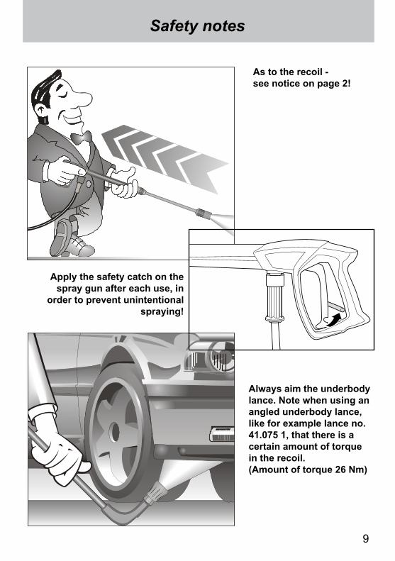
Safety notes
As to the recoil - see notice on page 2!
Always aim the underbody lance. Note when using an angled underbody lance, like for example lance no. 41.075 1, that there is a certain amount of torque in the recoil. (Amount of torque 26 Nm)
Apply the safety catch on the spray gun after each use, in
order to prevent unintentional spraying!
10
1. Spray lance with high pressure nozzle
2. Spray gun with insulated pistol grip and screw connection
3. KRÄNZLE - High pressure cleaners HD7/122 / HD 10/122
6. Water inlet components
This is what you’ve purchased:
is already installed
4. Steel braided high pressure hose 10 m, NW 6
5. Operating instructions
11
Preparation for use
2. Connect the high pressure lance to the spray gun.
High pressure hose connected to machine and spray gun.
1. Check oil level Oil has to be visible in the oil-level sight glass
3. Unroll hose without kinks and con-nect with handgun and pump. Max. extension 20 m-HP hose or 2 x 10 m with hose connections.
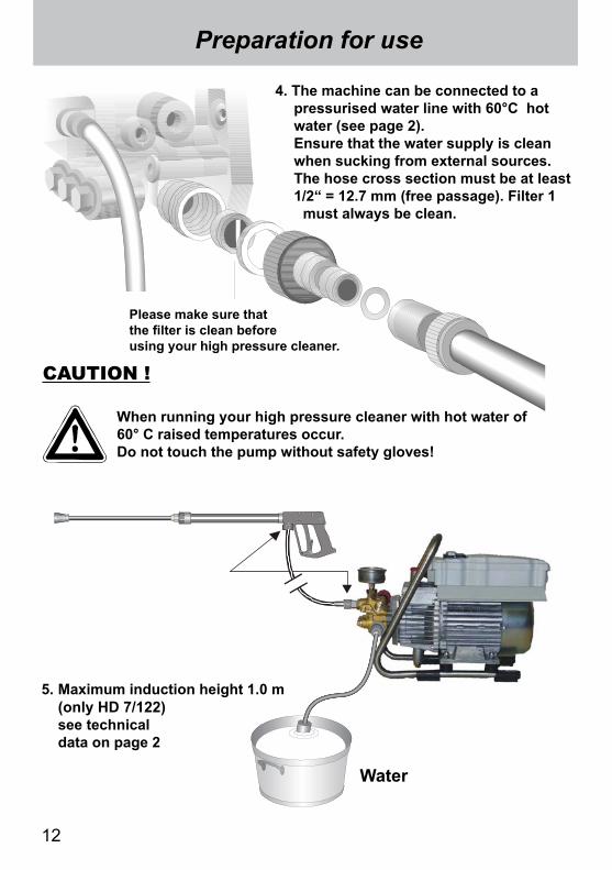
4. The machine can be connected to a pressurised water line with 60°C hot water (see page 2). Ensure that the water supply is clean when sucking from external sources. The hose cross section must be at least 1/2“ = 12.7 mm (free passage). Filter 1
must always be clean.
Please make sure that the filter is clean before using your high pressure cleaner.
CAUTION !
When running your high pressure cleaner with hot water of 60° C raised temperatures occur.Do not touch the pump without safety gloves!
Water
5. Maximum induction height 1.0 m (only HD 7/122) see technical data on page 2
Preparation for use
12
13
When running your high pressure cleaner with hot water of 60° C raised temperatures occur.Do not touch the pump without safety gloves!
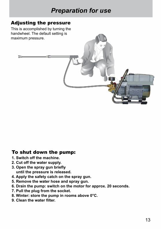
This is accomplished by turning the handwheel. The default setting is maximum pressure.
Adjusting the pressure
Preparation for use
1. Switch off the machine.2. Cut off the water supply.3. Open the spray gun briefly until the pressure is released.4. Apply the safety catch on the spray gun.5. Remove the water hose and spray gun.6. Drain the pump: switch on the motor for approx. 20 seconds.7. Pull the plug from the socket.8. Winter: store the pump in rooms above 0°C.9. Clean the water filter.
To shut down the pump:
14
This is prohibited !
Never direct the water jet at the machine itself !
Never direct the water jet at a power socket !
Never allow children to use the high pressure cleaner !
15
This is prohibited !
Never direct the water jet at people or animals !
Do not damage the power cable or repair it incorrectly !(Replace defective or damaged cables immediately !Never work with a defective app-liance !)
Never pull the high pressure hose if it has formed kinks or “nooses”!Never pull the hose over sharp edges !
16
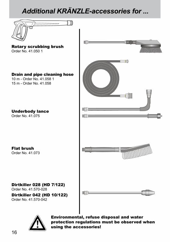
Flat brush Order No. 41.073
Dirtkiller 028 (HD 7/122) Order No. 41.570-028Dirtkiller 042 (HD 10/122) Order No. 41.570-042
Environmental, refuse disposal and water protection regulations must be observed when using the accessories!
Additional KRÄNZLE-accessories for ...
Rotary scrubbing brush Order No. 41.050 1
Drain and pipe cleaning hose 10 m - Order No. 41.058 115 m - Order No. 41.058
Underbody lance Order No. 41.075
17
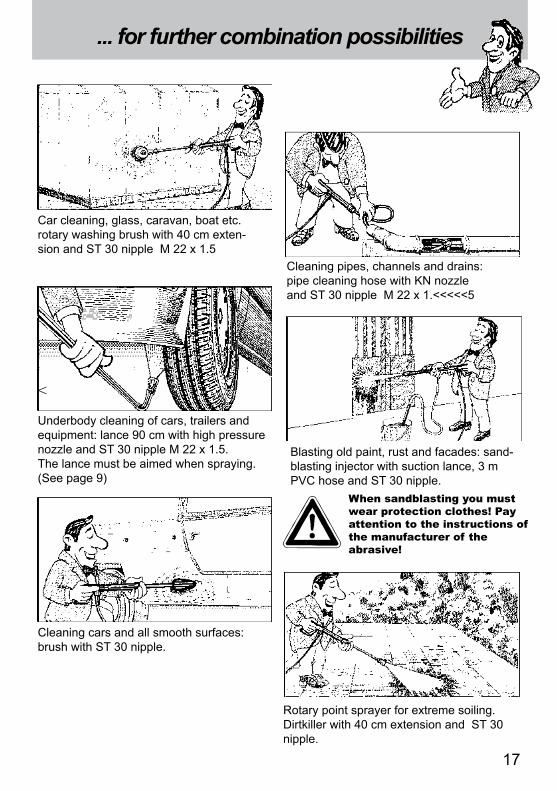
... for further combination possibilities
Car cleaning, glass, caravan, boat etc. rotary washing brush with 40 cm exten- sion and ST 30 nipple M 22 x 1.5
Underbody cleaning of cars, trailers and equipment: lance 90 cm with high pressure nozzle and ST 30 nipple M 22 x 1.5. The lance must be aimed when spraying.(See page 9)
Cleaning cars and all smooth surfaces: brush with ST 30 nipple.
Rotary point sprayer for extreme soiling. Dirtkiller with 40 cm extension and ST 30 nipple.
Cleaning pipes, channels and drains: pipe cleaning hose with KN nozzle and ST 30 nipple M 22 x 1.<<<<<5
Blasting old paint, rust and facades: sand-blasting injector with suction lance, 3 m PVC hose and ST 30 nipple.
When sandblasting you must wear protection clothes! Pay attention to the instructions of the manufacturer of the abrasive!
<
Small repairs -
18
Nozzle dirty or sticky!Pressure gauge does not show full pressure. Water comes out in spurts.If you do not use the high-pressure cleaner for some time the valves can stick
The high-pressure hose vibrates.
Straighten a paper clip...
When a valve is blocked, the gauge shows little pressure or no pressure
at all,
or the high pressure
hose vibra-tes!
Open the valve with a socket
wrench...
and remove the valve screw, the valve and the o-ring.
Replace the rubber o-ring.and remove the dirt from the valve - the valve inside must be closed.
Retighten the valve screw
...and repeat on all 6 valves.
Now it works as well as before!
19
The nozzle is blocked!No water but the gauge shows full pressure !
- Do it yourself!
Rinse the hose through first.
You should now have a powerful stream of water,
but if you only get a few
drops fromthe lance
remove the lance and clean the nozzle.
Using the flat spray lance you only have to clean the front
nozzle.
Straighten a paperclip and clean the
nozzle.Insert pointed object into the hole and pull the cap back!
Check visually whether the nozzle is clean.
Now it works as well as before.
20
Small repairs - Do it yourself!Stopping leaks from hose or gun
After closing the gun the manometer shows full pressure ! The pressure regulator switches on and off continuously!
If the manometer shows full pressure,
Press the trigger to
release the pressure!!!
First dis-connect the
hose!
Then unscrew the pump outlet with an open-jew wrench.
Clean the return element or replace
the O-Ring !
The pressure regulator switches on and off from pressure loss!
Water can emerge at these 3 points.
Check the seals and replace the O-Ringe if necessary
or ave the gun checked by the dealer.
Replace the O-Ring at the lance or at the HP hose respectively!
Reconnect the hose, gun and lance!
Problem solved already!
Pull out the power plug!
21
Gun with lance
No Description Qty. Ord.-No
M2000-Pistole kpl. 12.480 Lance compl. with HP-nozzle 028 12.393-M20028 Lance compl. with HP-nozzle 042 12.393-M20042
1 Pistolenschale re+li 1 12.4502 Schraube 3,5 x 14 10 44.5253 Reparatursatz M2000 12.45418 O-Ring 9,3 x 2,4 1 13.273
51 Düsenschutz M12x1 1 26.002 152 Rohr 500 mm; bds. M12x1 1 41.527 153 ST 30 Nippel M 22 x 1,5 / R1/4“ m. ISK 1 13.36354 Flachstrahldüse 028 (bei HD 7/122) 1 M2002854.1 Flachstrahldüse 042 (bei HD 10/122) 1 M2004255 Aluminium-Dichtring 2 13.275
22
Complete assembly
23
HD 7/122 / HD 10/122
No Description Qty. Ord.-No
Spare parts list KRÄNZLE HD 7/122 / HD 10/122Complete assembly
2 Tragbügel 1 44.581 3 Gummiprofilleiste 2 41.098 1 4 Senkschraube M6x20 1 43.473 1 5 Gummipuffer 30 x 20 4 46.023 1 6 Scheibe 8,4 4 41.409 7 Mutter DIN985 M8 4 41.4108 M2000-Pistole kpl. 12.4809 Lanze mit Flachstrahldüse 028 (HD 7/122) 12.393-M200289.1 Lanze mit Flachstrahldüse 042 (HD 10/122) 12.393-M2004210 Schmutzkiller 028 kpl. mit Lanze (HD 7/122) 41.570-02810.1 Schmutzkiller 042 kpl. mit Lanze (HD 10/122) 41.570-04219 O-Ring 9,3 x 2,4 2 13.27320 HD-Schlauch NW 6 10 m 210 bar 1 43.416
24
Motor
25
No Description Qty. Ord.-No
KRÄNZLE HD 7/122 / HD 10/122
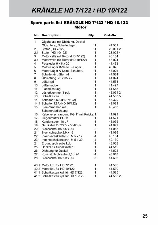
Spare parts list KRÄNZLE HD 7/122 / HD 10/122 Motor
1 Ölgehäuse mit Dichtung, Deckel Öldichtung, Schulterlager 1 44.501 2 Stator (HD 7/122) 1 23.001 2 2.1 Stator (HD 10/122) 1 23.002 4 3 Motorwelle mit Rotor (HD 7/122) 1 43.104 3.1 Motorwelle mit Rotor (HD 10/122) 1 43.024 4 Passfeder 6 x 6 x 20 1 41.483 1 5 Motor-Lager B-Seite Z-Lager 1 43.025 6 Motor-Lager A-Seite Schulterl. 1 43.0267 Schelle für Lüfterrad 1 44.534 1 8 Öldichtung 25 x 35 x 7 1 41.024 9 Lüfterrad 1 44.534 10 Lüfterhaube 1 41.497 11 Flachdichtung 1 44.513 12 Lüsterklemme 3-pol. 1 43.031 2 13 Schaltkasten 1 44.508 5 14 Schalter 8,5 A (HD 7/122) 1 43.329 14.1 Schalter 12 A (HD 10/122) 1 43.033 15 Klemmrahmen mit 1 43.453 Schalterabdichtung16 Kabelverschraubung PG 11 mit Knicks. 1 41.091 17 Gegenmutter PG 11 1 44.521 18 Kondensator 40 µF 1 43.035 19 Netzkabel für 230V / 50/60Hz 1 41.092 20 Blechschraube 3,5 x 9,5 2 41.088 21 Blechschraube 2,9 x 16 1 43.036 22 Innensechskantschr. M 5 x 12 4 40.134 23 Innensechskantschr. M 5 x 30 4 42.130 24 Erdungsschraube kpl. 1 43.03825 Deckel für Schaltkasten 1 44.51226 Dichtung für Deckel 1 44.52227 Kunststoffschraube 5,0 x 20 4 43.01828 Blechschraube 3,9 x 9,5 3 41.636
40.1 Motor kpl. für HD 7/122 1 44.58640.2 Motor kpl. für HD 10/122 1 44.53041.1 Schaltkasten kpl. für HD 7/122 1 44.585 141.2 Schaltkasten kpl. für HD 10/122 1 44.585 2
26
Transmission
27
KRÄNZLE HD 7/122 / HD 10/122
No Description Qty. Ord.-No
Spare parts list KRÄNZLE HD 7/122 / HD 10/122Transmission
1 Gehäuseplatte 1 43.0032 Öldichtung 14 x 24 x 7 3 41.6313 O-Ring 83 x 2 1 43.0394 Plungerfeder 3 43.0405 Federdruckscheibe 14 mm 3 43.0416 Plunger 14 mm AZ-L 3 49.0217 Sprengring 14 mm 3 41.6358.1 Taumelscheibe 12,5° (HD 7/122) 1 41.028-12,58.2 Taumelscheibe 9,75° (HD 10/122) 1 41.028-9,7510 Axial-Rillenkugellager 3-teilig 1 43.48612 Innensechskantschraube M 8 x 25 4 40.05313 Ölablassstopfen M18x1,5 mit Magnet 1 48.02014 O-Ring 12 x 2 3 15.005 115 Ölschauglas 1 42.018 116 Ölverschlussschraube rot 1 43.43717 Dichtung Öldeckel 1 44.501 118 Deckel Ölgehäuse 1 44.501 219 Innensechskantschraube M 5 x 12 4 41.019 4
28
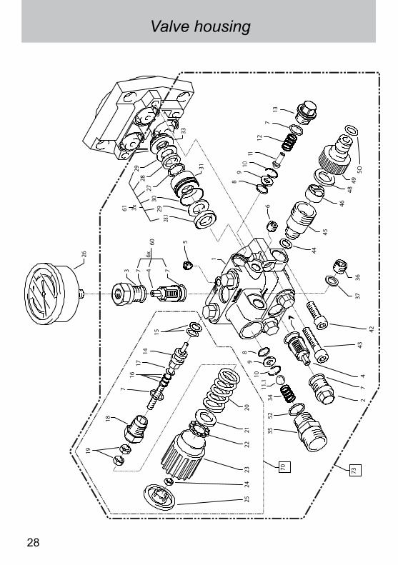
Valve housing
19
18
716
1714
15
3
26
27
4
3552
11.1
98
2524
2322
2120
34
10
7
47
45
4648
495O
44
3736
42
43
6
2930
3129
33
2760
6x
61 3x
28.1
28
7
70
1
73
5
89
1011
127
13
29
KRÄNZLE HD 7/122 / HD 10/122S
pare
par
ts li
st K
RÄ
NZ
LE H
D 7
/122
/ H
D 1
0/12
2 V
alve
hou
sing
No
Des
crip
tion
Q
ty. O
rd.-N
oN
o D
escr
ipti
on
Qty
. O
rd.-N
o
1 Ve
ntilg
ehäu
se
1 49
.020
1
2 Ve
ntils
topf
en
5 41
.011
3
Vent
ilsto
pfen
mit
R1/
4“ IG
1
41.0
11 1
4 Ve
ntile
(rot
) (H
D 1
0/12
2)
6 41
.612
4.
1 Ve
ntile
(grü
n) (H
D 7
/122
) 6
41.6
12 1
5
Dic
htst
opfe
n M
8 x
1
1 13
.158
6
Dic
htst
opfe
n M
10
x 1
1 43
.043
7
O-R
ing
12 x
2
14
15.0
05 1
8
O-R
ing
11 x
1,5
2
12.2
56
9 E
dels
tahl
sitz
2
14.1
18
10
Sic
heru
ngsr
ing
2 13
.147
11
A
nlau
fent
last
ungs
vent
il 1
49.0
41 1
11.1
Ede
lsta
hlku
gel
10,0
mm
1
12.1
22
12
Ede
lsta
hlfe
der
1 49
.042
13
Ve
rsch
luss
schr
aube
1
49.0
43
14
Ste
uerk
olbe
n 6
mm
für A
Z 1
44.5
32
m
it D
icht
unge
n15
P
arba
ks fü
r Kol
ben
14 m
m
1 14
.123
116
P
arba
ks fü
r Spi
ndel
6 m
m
1 14
.123
217
M
S-S
chei
be
1 43
.045
18
Kol
benf
ühru
ng 6
mm
1
14.1
30 1
19
Mut
ter
M 6
2
14.1
27 1
20
Fede
r sch
war
z fü
r AZ-
Pum
pe
1 43
.046
21
Fe
derd
ruck
sche
ibe
1 43
.047
22
Kug
ella
ger
1 43
.048
23
Han
drad
M 6
für A
Z-P
umpe
1
43.0
4924
M
utte
r M
6 m
it S
W 8
1
43.0
1025
K
appe
für H
andr
ad A
Z-P
umpe
1
43.0
5026
M
anom
eter
1
15.0
3927
S
tütz
ring
3 41
.618
28
Man
sche
tte 1
4 x
24 x
5/2
,5
3 41
.613
28.1
Gew
ebe-
Man
sche
tte 1
4 x
24 x
5/2
,5
3 41
.613
129
B
ackr
ing
14
x 24
6
41.6
14
30
O-R
ing
24
x 2
3 49
.024
31
Leck
ager
ing
3 49
.022
33
Zwis
chen
ring
mit
Abs
tütz
ung
3 43
.055
34
Rüc
ksch
lagf
eder
1
14.1
20 1
35
Aus
gang
stei
l für
Kug
elrü
cksc
hlag
v.
1 40
.522
136
Ve
rsch
luss
topf
en
1 13
.181
37
Alu
min
ium
-Dic
htrin
g 2
13.2
7542
In
nens
echs
kant
schr
. M
8 x
25
- A2
2 40
.053
43
Inne
nsec
hska
ntsc
hr.
M 8
x 4
5 - A
2 2
41.0
17
44
Dic
htrin
g K
upfe
r 1
14.1
49
45
Sau
gans
chlu
ss
1 41
.016
46
W
asse
rfilte
r 1
41.0
46 2
48
Gum
mi D
icht
ring
1 41
.047
1
49
Ste
ckku
pplu
ng
1 41
.047
250
O
-Rin
g 1
41.0
47 3
52
O-R
ing
18 x
2
1 43
.446
60
Rep
.-Sat
z Ve
ntile
(rot
) (H
D 1
0/12
2)
41
.648
60.1
Rep
.-Sat
z Ve
ntile
(grü
n) (H
D 7
/122
)
41.6
48 1
61
Rep
arat
ur-S
atz
Man
sche
tten
49
.053
70
Steu
erko
lben
kpl
. m. H
andr
ad
44
.532
173
Ve
ntilg
ehäu
se (H
D 1
0/12
2) k
pl.
44
.590
173
.1 V
entil
gehä
use
(HD
7/1
22) k
pl.
44
.590
2
30
Dirtkiller (special accessory)
Spare parts list Dirtkiller
No Description Qty. Ord.-No
Schmutzkiller 028 kpl. mit Lanze 41.570-028 Schmutzkiller 042 kpl. mit Lanze 41.570-042
1 Sprühkörper 1 41.5202 O-Ring 6,88 x 1,68 1 41.5213 Düsensitz 1 41.5224 Düse 028 (HD 7/122) 1 41.523-0284.1 Düse 042 (HD 10/122) 1 41.523-0425 Stabilisator 1 41.5246 O-Ring 1 40.016 17 Sprühstopfen 1 41.5268 Rohr 500 mm 2x M 12 x 1 1 41.527 19 ST 30-Nippel M 22 x 1,5 / M 12 x 1 ISK 1 13.36311 Kappe vorn für Schmutzkiller 1 41.528 112 Kappe hinten für Schmutzkiller 028 (HD 7/122) 1 41.542 312.1 Kappe hinten für Schmutzkiller 042 (HD 10/122) 1 41.540 210 Rep.-Satz Schmutzkiller 028 41.096 4 bestehend aus je 1x 2; 3; 4; 510.1 Rep.-Satz Schmutzkiller 042 41.096 5 bestehend aus je 1x 2; 3; 4; 5
31
Terminal strip
Weber-Unimat WT 22 - 551 8,5A excess current release (HD 7/122)12A excess current release (HD 10/122)
Motor-Stator
Wiring diagram for KRÄNZLE HD 7/122 / HD 10/122
Wiring diagram / Warranty
C : 40 µF braun = brownblau = blueschw = blackrt = redge = yellowgn = greenws = white
GuaranteeThe guarantee is only valid for material and manufacturing errors. Wearing does not fall within this gurantee.
The instructions in our operating manual must be complied with. The operating instructions form part of the guarantee. The Guarantee is void if other parts are used than genuine Kränzle accessory parts or genuine Kränzle spare parts.
For high-pressure cleaners sold to the user the guarantee period is 24 month.
For high-pressure cleaners sold for industrial use the guarantee period is 12 month. In the case of a guarantee please contact your dealer or authorized seller delivering accessories and your purchase receipt. You can find them in the internet under www.kraenzle.com.
The guarantee is also void if the machine is used with exceeding the temperature and speed limits, a voltage below the required rating, with less than the required amount of water or with dirty water. Pressure gauge, nozzle, valves, sleeves, high pressure hose and spray equipment are wear parts and are not covered by the warranty.
32
InspectionsThe machine must be inspected according to the “Guidelines for Liquid Spray De-vices” at least once every 12 months by a qualified person, to ensure that contin-ued safe operation is guarateed. The results of the inspection are to be recorded in writing. This may be done in any form.
Accident preventionThe machine is designed for accidents to be impossible if used correctly. The operator is to be notified of the risk of injury from hot machine parts and the high pressure water jet. The “Guidelines for Liquid Spray Devices” must be com-plied with. (see page 14 and 15)
Oil change:Check the oil level at the oil sight glass prior to each use.(Ensure horizontal position!) The oil level should be at the middle of the sight glass. With high atmospheric humidity and temperature fluctuation there may be condensation (oil has a greyish colour); Then the oil must be changed.First oil change after approx 50 hours of operation. Thereafter, no more oil change is required for the lifetime of the equipment. If it becomes necessary during re-pairs, or because the oil has a greyish colour to perform an oil change, then the oil sight glass should be opened and the oil emptied into a container. The oil must be caught in a container and disposed of in a responsible, legal manner.New oil: 0.25 l - Motor oil: 10 W40
Oil leakIn the event of an oil leak contact customer service (dealer) immediately. (damage to environment or transmission)
General rules
Kränzle Josef
I. Kränzle GmbHElpke 97 33605 Bielefeld
High-pressure-cleanersHochdruckreiniger
Nettoyeurs À Haute Pression
33(Managing Director)
EC declaration of conformity
Bielefeld, Sept.03.2012
We hereby declare,that the high-pressure models:
(techn. documentation available from):
Nominal flow
comply with the following guidelines and specifications and their amend-ments for high-pressure cleaners:
Sound power level measured: guaranteed:
Applied conformity evaluation proce-dures
Applied specifications andstandards:
Kränzle HD 7/122Kränzle HD 10/122
Manfred Bauer, Fa. Josef Kränzle Rudolf-Diesel-Str. 20, 89257 Illertissen
HD 7/122: 420 l/h; HD 10/122: 600 l/h
Machine guideline 2006/42/EEC Specification for electromagnetic compatibility 2004/108/EECOutdoor noise directive 2005/88/EC, Art. 13, High-pressure water jet machi-nes Appendix 3, part B, chapter 27
HD 7/122: 81 dB (A); HD 10/122: 89 dB (A)HD 7/122: 84 dB (A); HD 10/122: 91 dB (A)
Annex V, noise directive 2005/88/EC
EN 60 335-2-79 :2009EN 55 014-1 :2006EN 61 000-3-2 :2006 EN 61 000-3-3 :2008
34
Notes
35
Notes
Subj
ect
to t
echn
ical
mod
ific
atio
ns. O
rder
no.
30.
800
1
I . K r ä n z l e G m b HE l p k e 9 7
D - 3 3 6 0 5 B i e l e f e l d
R e p r i n t o n l y a l l o w e d w i t h t h e a u t h o r i s a t i o n o f K r ä n z l e .


![CODE: D431388XA- VERS. 3.0 GB · VECTRA 1998 1999 ORIGINAL 4 ZAFIRA[ATW] 1999 ORIGINAL 22 ZAFIRA 1999 ORIGINAL 4 This SW upgrade makes it possible to: - Add/Delete Keys/Remote Controls](https://static.documents.pub/doc/80x56/60655ee79a88763df84de02a/code-d431388xa-vers-30-gb-vectra-1998-1999-original-4-zafiraatw-1999-original.jpg)


