12
OSS Side Access Expandable Device Assembly and Expansion Guide

OSS Side Access Expandable DeviceAssembly and Expansion Guide
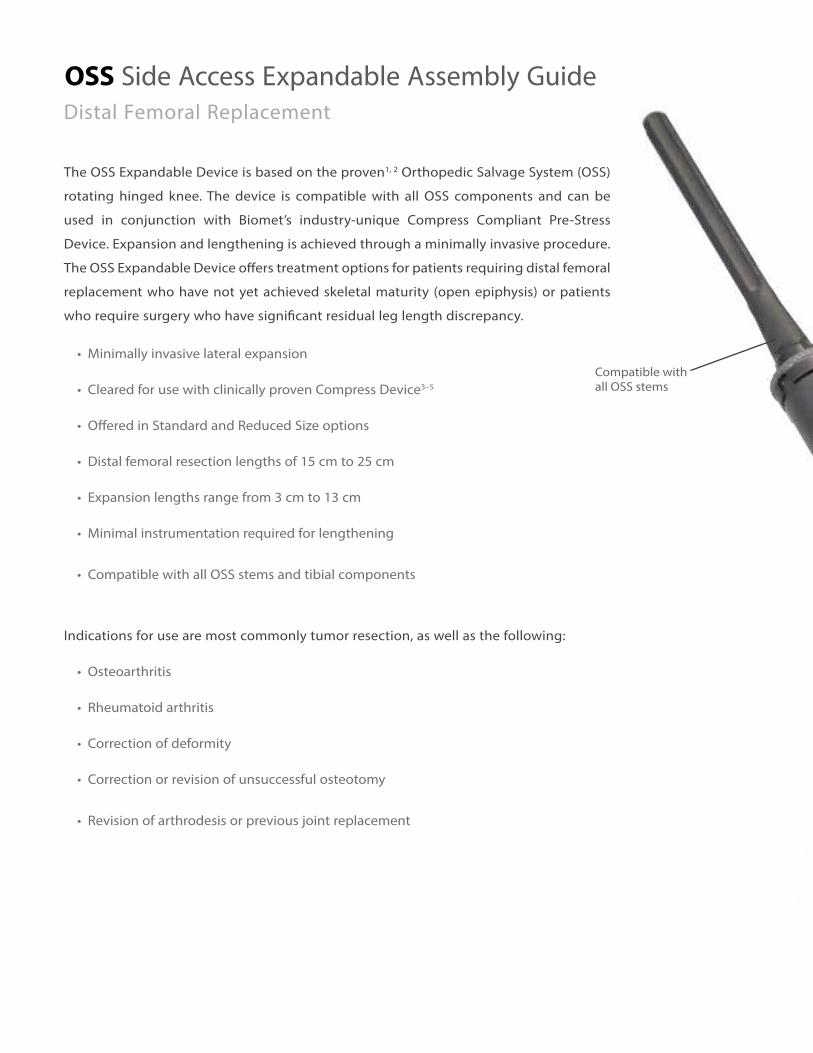
OSS Side Access Expandable Assembly GuideDistal Femoral Replacement
The OSS Expandable Device is based on the proven1, 2 Orthopedic Salvage System (OSS)
rotating hinged knee. The device is compatible with all OSS components and can be
used in conjunction with Biomet’s industry-unique Compress Compliant Pre-Stress
Device. Expansion and lengthening is achieved through a minimally invasive procedure.
The OSS Expandable Device offers treatment options for patients requiring distal femoral
replacement who have not yet achieved skeletal maturity (open epiphysis) or patients
who require surgery who have significant residual leg length discrepancy.
• Minimally invasive lateral expansion
• Cleared for use with clinically proven Compress Device3–5
• Offered in Standard and Reduced Size options
• Distal femoral resection lengths of 15 cm to 25 cm
• Expansion lengths range from 3 cm to 13 cm
• Minimal instrumentation required for lengthening
• Compatible with all OSS stems and tibial components
Indications for use are most commonly tumor resection, as well as the following:
• Osteoarthritis
• Rheumatoid arthritis
• Correction of deformity
• Correction or revision of unsuccessful osteotomy
• Revision of arthrodesis or previous joint replacement
• Compatible with all OSS stems
Compatible with all OSS stems
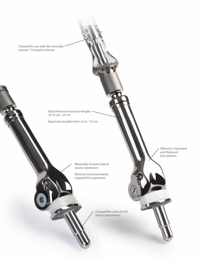
Minimally invasive lateral access expansion
Minimal instrumentation required for expansion
Distal femoral resection lengths of 15 cm –25 cm
Expansion lengths from 3 cm –13 cm
Cleared for use with the clinically proven3-5 Compress Device
Offered in Standard and Reduced Size options
• Compatible with all OSS stems
Compatible with all OSS tibial components

2
OSS Side Access Expandable Assembly Guide
Pre-operative planning:Sizing is based upon the length of the femoral resection and includes the Expandable Device plus 1 cm Compress Spindle or OSS Stem via a 1 cm OSS taper to Compress Taper Adapter (part no. 178548) (Figure 1 and 2).
Note: The product length found on the packaging label includes the length of the 1 cm adapter (ordered separately) or 1 cm Compress Spindle.
Expansion length capabilities related to resection length of device are shown in Chart 1.
Femoral Canal PreparationPlease reference the OSS Segmental Distal Femoral Surgical Technique (BOI0214.0) or the Compress Compliant Pre-Stress Device Surgical Technique (BMET0247.0) for suggested femoral canal preparation.
Tibial PreparationPlease reference the OSS Segmental Distal Femoral Surgical Technique (BOI0214.0) for suggested tibial preparation.
Note: Patellas smaller than 31 mm are not recommended.
Resection LengthExpansion Length
Capability
15 cm 3 cm
16 cm 4 cm
17 cm 5 cm
18 cm 6 cm
19 cm 7 cm
20 cm 8 cm
21 cm 9 cm
22 cm 10 cm
23 cm 11 cm
24 cm 12 cm
25 cm 13 cm
Distal Femoral Replacement
15 cm – 25 cm lengths15 cm – 25 cm lengths
1 cm Compress Spindle1 cm OSS to Compress Taper Adapter
Actual Length is 14 cm – 24 cm Actual Length is 14 cm – 24 cm
Figure 1 Figure 2
Chart 1

3
1 cm OSS to Compress Taper Adapter
Trial SelectionPlease reference the OSS Segmental Distal Femoral Surgical Technique (BOI0214.0) or the Compress Compliant Pre-Stress Device Surgical Technique (BMET0247.0) for suggested femoral and tibial trialing (Figure 3).
Implantation of ConstructIf implanting the Expandable Device with the Compress Spindle, impact the Expandable Device to the Spindle utilizing the OSS modular femoral impactor (Figure 4).
If implanting with an OSS stem, unscrew the large head/small thread locking screw from the stem and set aside. Impact stem to the OSS-to-Compress adapter and secure with the large head/small thread locking screw. Impact the expandable device to the stem construct utilizing the OSS modular impactor and stem holder. Implant the construct into the prepared femoral canal (Figure 5).
Figure 3 Figure 4 Figure 5

4
OSS Side Access Expandable Assembly Guide
Subsequent Expansion ProcedureLocate the access point on the lateral side of the implant.
For the Reduced Size option, the center of the hex is approximately 32 mm above the joint line, 9 mm posterior to the anterior prominence of the patella track, and 37 mm anterior to the posterior condyles (Figure 6).
For the Standard option, the center of the hex is approximately 32 mm above the joint line, 16 mm posterior to the anterior prominence of the patella track, and 41 mm anterior to the posterior condyles (Figure 7).
Note: The above dimensions are constant regardless of the resection length of the device.
Note: The additional screw located inferior and slightly posterior to the 5 mm recessed hex must NOT be tightened or loosened in the operating room. A 5 mm hex driver will not inadvertently engage the 2.5 mm recessed hex of the additional screw. This additional screw is meant to be tightened ONLY at the manufacturing facility. It does not lock the expansion mechanism to prevent unintentional shortening of the implant. Friction and the extremely high mechanical advantage of the internal mechanism resist unintentional shortening of the implant.
Distal Femoral Replacement
Figure 6 – Hex location on RS Expandable Figure 7 – Hex Location on Standard Expandable
32 mm 32 mm
9 mm 16 mm37 mm 41 mm

5
Subsequent Expansion Procedure (cont.)In a lateral view of the device, the center of the 5 mm recess is on a theoretical anterior-to-posterior line running across the top of the condyle radii. It also lies on a theoretical line running parallel to the expansion axis that touches the anterior edge of narrowest part of the expandable, just below the taper (Figure 8 and Figure 9).
Figure 8 – 5 mm Recess Location on RS Expandable Figure 9 – 5 mm Recess Location on Standard Expandable

6
OSS Side Access Expandable Assembly GuideDistal Femoral Replacement
Subsequent Expansion Procedure (cont.)Once the 5 mm recessed hex has been accessed, place the 5 mm straight hex driver or 5 mm ball hex driver into the recessed hex (Figure 10 and Figure 11).
Note: Either hex driver may be used. The straight hex driver provides a more tactile confirmation that the driver is seated in the recessed hex. The ball hex driver is more tolerant of misalignment of the axis of the driver.
Figure 10Straight Hex Driver
Figure 11Ball Hex Driver

7
Subsequent Expansion Procedure (cont.)Connect the revolution counter via the Zimmer-Hudson end of the shaft to the drill (Figure 12).
Using the drill setting, turn the revolution counter in either direction until the “10 mm” mark on the dial is centered in the viewing window (Figure 13).
Figure 12 Figure 13

8
OSS Side Access Expandable Assembly Guide
Subsequent Expansion Procedure (cont.)Assemble the revolution counter to the 5 mm hex driver by pulling back the ring on the revolution counter shaft (Figure 14).
It takes 142 counter-clockwise turns to expand the device 1 cm. The revolution counter displays the number of millimeters past a whole centimeter of amount of expansion that has been achieved. The numbers on the instrument dial start at “10 mm” (corresponding to 0 mm) and goes through “9 mm” in 1 mm increments before going back to “10 mm” (Figure 15). Every time the “10 mm” passes in and out of the viewing window, an additional 1 cm of expansion is achieved (it takes 142 turns to rotate the numbered dial on the instrument once) and the surgeon should use a marker to make a clear tick mark on a surgical drape to indicate that an additional whole 1 cm has been achieved. The total amount of expansion achieved at any time is the number of tick marks recorded times 1 cm added to the millimeter amount displayed in the window of the instrument. For example: 2 tick marks recorded on the drape plus “3 mm” displayed in the window means that 2.3 cm of total expansion has been achieved.
Note: Expansion is displayed in the window as millimeters with the maximum display of 9 mm. To expand beyond 1 cm, the counter will start again at 10 mm (Figure 15 inset).
Note: The expandable implant can be contracted (shortened) with clockwise turns, but ONLY after it has been expanded. The implant cannot be contracted by a greater amount than it has been expanded. Use the revolution counter during shortening to make sure that the total amount of contraction does not exceed the total amount of expansion (the revolution counter will count backwards). It is recommended to create a tick mark on a different area of the surgical drape for each 1 cm the product is contracted. If the implant is being contracted and reaches its original length a torque-limiting feature built into the expansion instrument will prevent over-contraction. The torque limiter will make an audible clicking sound and allow slippage between the input and output ends of the expansion instrument. Any attempt to manually bypass the torque limiting device in order to shorten the implant past the as-manufactured length can cause permanent damage to the internal expansion mechanism of the implant.
The final amount of expansion achieved can be visualized under fluoroscope. It is helpful to document the total amount of expansion achieved in a given procedure.
Figure 14 Figure 15
Distal Femoral Replacement

References
1. Molenaers, B. et al. Complex total knee arthroplasty using resection prostheses at mid-term follow-up. The Knee. 19: 550-554, 2012.
2. Berend, K. et al. Distal Femoral Replacement in Nontumor Cases with Severe Bone Loss and Instability. Clinical Orthopaedics and Related Research. 467:485-492, 2009.
3. Healey, J. et al. Compress Knee Arthroplasty Has 80% 10-year Survivorship and Novel Forms of Bone Failure. Clinical Orthopaedics and Related Research. 471:774-783, 2012.
4. Avedian, R. et al. Effect of Chemotherapy on Initial Compressive Osseointegration of Tumor Endoprostheses. Clinical Orthopaedics and Related Research. 459: 48-53, 2007.
5. 2. Bini, S. et al. Compliant Prestress Fixation in Tumor Prostheses: Interface Retrieval Data. Orthopedics. 23(7): 707-12, 2000.

This publication and all content is protected by copyright, trademarks and other intellectual property rights owned by or licensed to Biomet Inc. or its affiliates unless otherwise indicated.
This material is intended for the sole use and benefit of the Biomet sales force and physicians. It is not to be redistributed, duplicated or disclosed without the express written consent of Biomet.
For product information, including Indications for Use, Contraindications, Warnings, Precautions and Possible Adverse Effects, see the package insert, and Patient Risk Information at www.biomet.com.
Biomet does not practice medicine. The treating surgeon is responsible for determining and utilizing the appropriate treatment, techniques, and products for each individual patient.
Responsible ManufacturerBiomet Orthopedics P.O. Box 58756 E. Bell DriveWarsaw, Indiana 46581-0587 USA
www.biomet.com©2014 Biomet Orthopedics • Form No. BMET0968.0 • REV1014
Authorized RepresentativeBiomet UK, Ltd.Waterton Industrial EstateBridgend, South WalesCF31 3XA UK
Over 1 million times per year, Biomet helps one surgeon provide personalized care to one patient.
The science and art of medical care is to provide the right solution for each individual patient. This requires clinical mastery, a human connection between the surgeon and the patient, and the right tools for each situation.
At Biomet, we strive to view our work through the eyes of one surgeon and one patient. We treat every solution we provide as if it’s meant for a family member.
Our approach to innovation creates real solutions that assist each surgeon in the delivery of durable personalized care to each patient, whether that solution requires a minimally invasive surgical technique, advanced biomaterials or a patient-matched implant.
When one surgeon connects with one patient to provide personalized care, the promise of medicine is fulfilled.
One Surgeon. One Patient.


