OU1 RD/RA Work Plan Washington Gas East Station Site OU1 Remedial Design and Remedial Action Work Plan (Final) Site: Washington Gas East Station Site 12 th and Water Street, SE Washington, DC Prepared for: Washington Gas Light Company 6801 Industrial Road Springfield, VA 22151 Prepared by: AECOM 4840 Cox Road Glen Allen, VA 23060 September 2014 AECOM Project No. 60277480
Transcript
OU1 RD/RA Work Plan Washington Gas East Station Site
OU1 Remedial Design and Remedial Action Work Plan (Final)
Site: Washington Gas East Station Site 12th and Water Street, SE Washington, DC Prepared for: Washington Gas Light Company 6801 Industrial Road Springfield, VA 22151 Prepared by: AECOM 4840 Cox Road Glen Allen, VA 23060 September 2014 AECOM Project No. 60277480
AECOM Washington Gas OU1 RD/RA Work Plan – East Station Site
7.4 Mobilization and Site Preparation ....................................................................................... 7-3 7.4.1 Fencing ................................................................................................................. 7-4 7.4.2 E&S Control .......................................................................................................... 7-4 7.4.3 Trash Removal and Tree Clearing ...................................................................... 7-5 7.4.4 Utility Clearances.................................................................................................. 7-6 7.4.5 Protection of Monitoring Wells and Seawall ........................................................ 7-6 7.4.6 Demolition of Structures ....................................................................................... 7-7 7.4.7 Health and Safety Control Measures................................................................... 7-7 7.4.8 Vehicle/Equipment Decontamination Pad ........................................................... 7-8 7.4.9 Dust and Dirt Control ............................................................................................ 7-9
C-06 Erosion and Sediment Control Standard Details
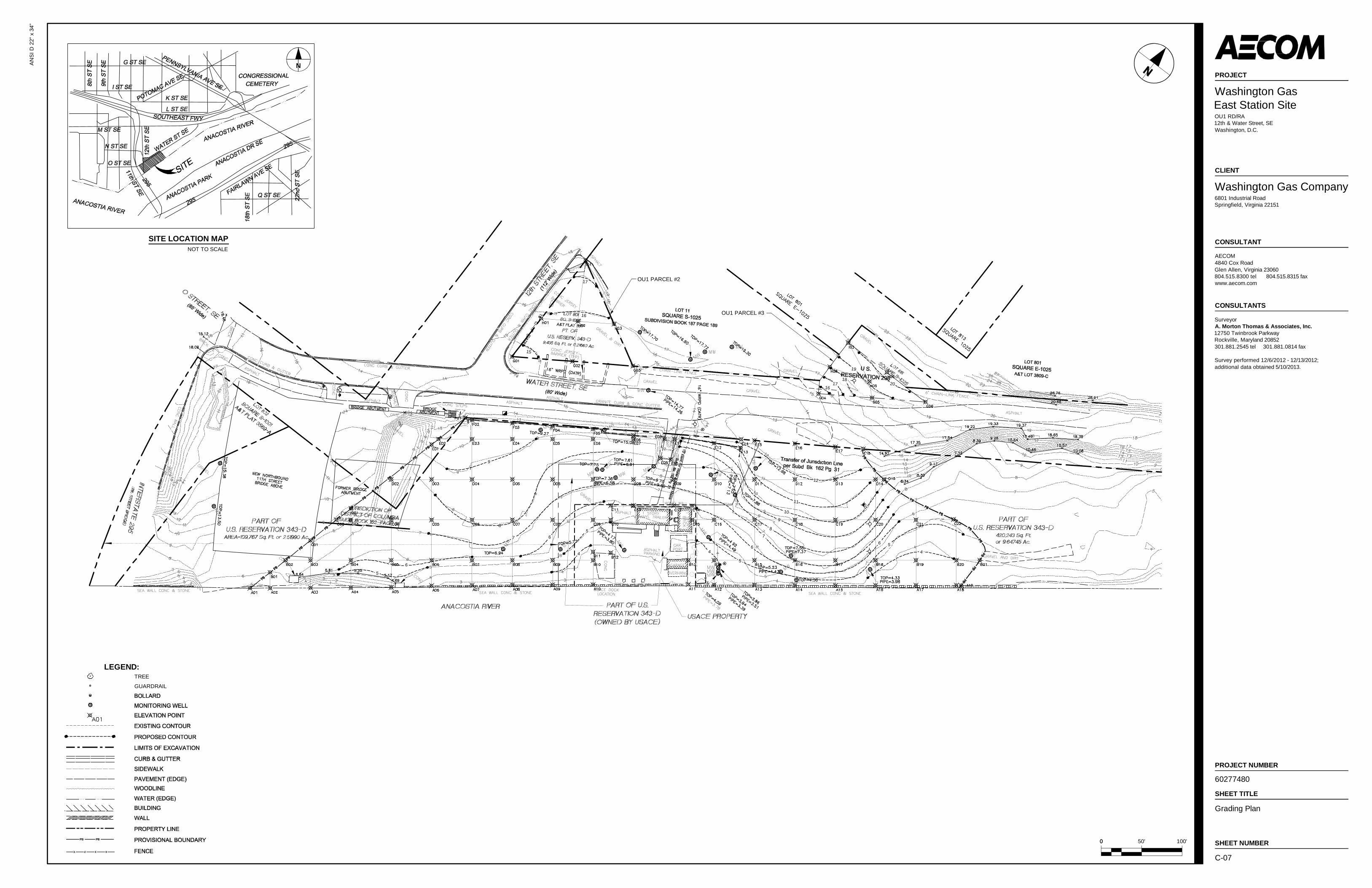
C-07 Grading Plan
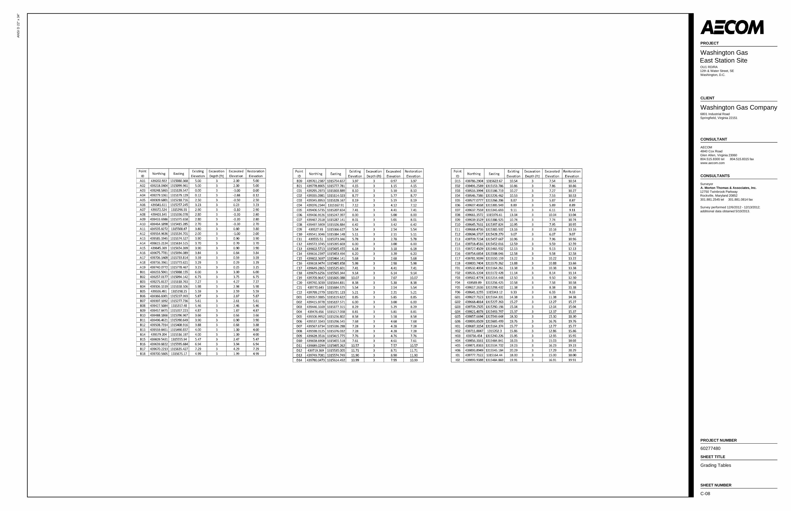
C-08 Grading Tables
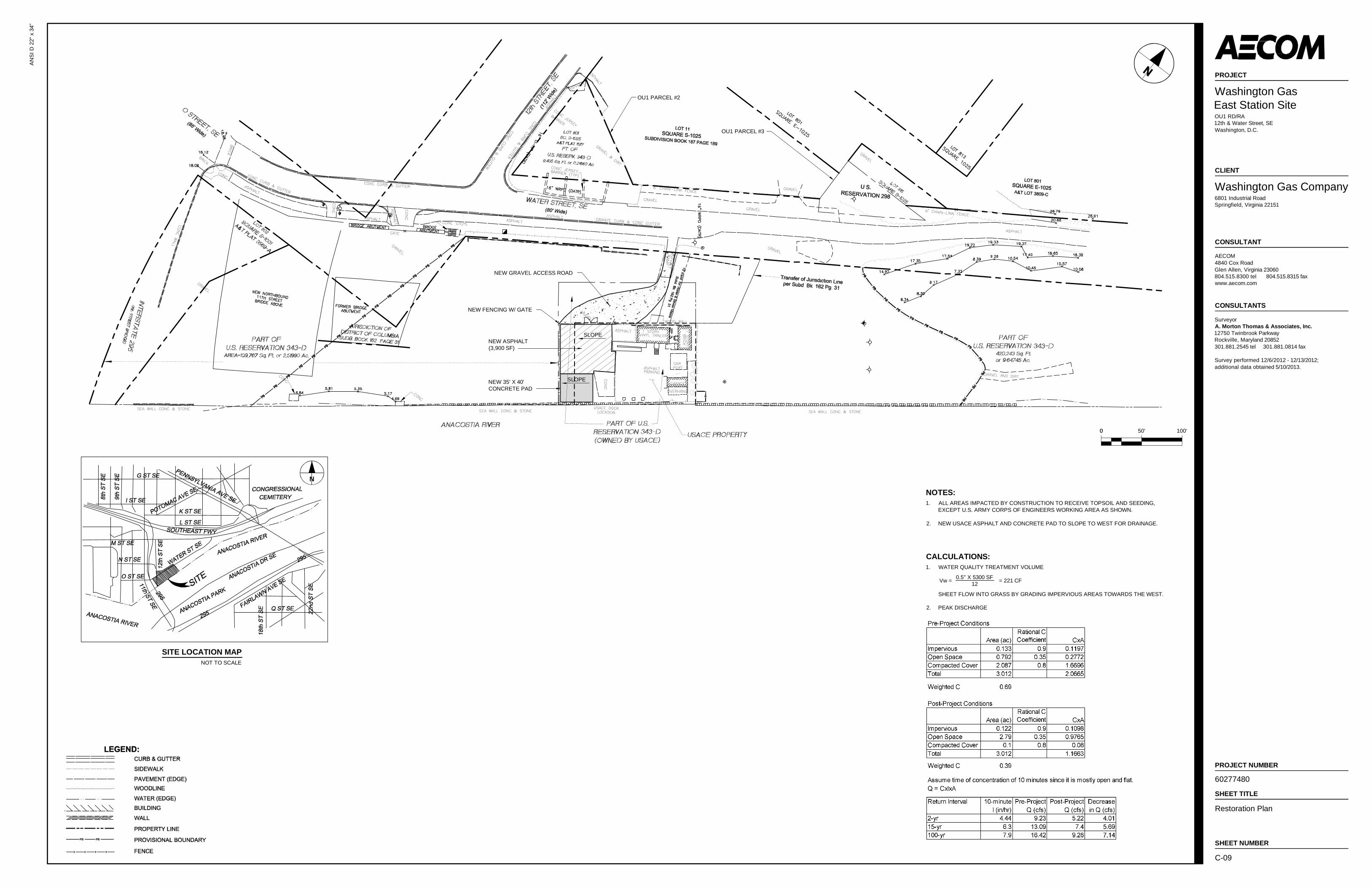
C-09 Restoration Plan
AECOM Washington Gas OU1 RD/RA Work Plan – East Station Site
September 2014
iv
Attachments
Attachment 1 NPS November 13, 2013 No Adverse Impact Letter to SHPO and SHPO November 21, 2013 Concurrence
Attachment 2 USFWS May 9, 2013 No Endangered/Threatened Species Impact Letter to AECOM
AECOM Washington Gas OU1 RD/RA Work Plan – East Station Site
September 2014
iv
List of Acronyms
µg/m3 Micrograms per cubic meter AASHTO American Association of State Highway and Transportation Officials AMP Air Monitoring Plan AMT A. Morton Thomas & Associates, Inc. ARARs Applicable or Relevant and Appropriate Requirements bgs Below Grade Surface BTEX Benzene, Toluene, Ethylbenzene, and Xylenes C&D Construction and Demolition CD Consent Decree CENC Clean Earth of New Castle CERCLA Comprehensive Environmental Response, Compensation, and Liability Act CFR Code of Federal Regulations CO Carbon Monoxide COC Contaminant of Concern CQA Construction Quality Assurance CQAP Construction Quality Assurance Plan CRZ Contamination Reduction Zone CY Cubic Yard DC District of Columbia DCDPW DC Department of Public Works DCMR DC Municipal Regulation DCRA District Department of Consumer and Regulatory Affairs DDOE District Department of the Environment DDOT DC Department of Transportation DoD Department of Defense DOT Department of Transportation DQO Data Quality Objective DRO Diesel Range Organics E&S Erosion and Sediment eV Electron Volts EZ Exclusion Zone FSP Field Sampling Plan Ft Foot or feet GPS Global Positioning System GRO Gasoline Range Organics H2S Hydrogen Sulfide HASP Health and Safety Plan HDPE High-Density Polyethylene IC Institutional Control ICIAP Institutional Controls Implementation and Assurance Plan LEL Lower Explosive Limit MG Manufactured Gas NELAP National Environmental Laboratory Accreditation Program NHPA National Historic Preservation Act NPDES National Pollutant Discharge Elimination System NPS National Park Service O2 Oxygen OU Operable Unit PAH Polycyclic Aromatic Hydrocarbon
AECOM Washington Gas OU1 RD/RA Work Plan – East Station Site
September 2014
v
List of Acronyms (continued)
PCB Polychlorinated Biphenyl PID Photoionization Detector PM Project Manager PM10 Particulate Matter less than 10 Micrometers in Size POP Project Operation Plan PPE Personal Protective Equipment QAPP Quality Assurance Project Plan QA/QC Quality Assurance/Quality Control RA Remedial Action RAO Remedial Action Objectives RCRA Resource Conservation and Recovery Act RD Remedial Design RI/FS Remedial Investigation/Feasbility Study ROD Record of Decision SAP Sampling and Analysis Plan SH&E Safety, Health, and Environmental SHPO State Historic Preservation Office SMDD Standard Maximum Dry Density SMP Site Management Plan SOP Standard Operating Procedure SOW Statement of Work SSO Site Safety Officer SVOC Semi-Volatile Organic Compound SZ Support Zone TCLP Toxicity Characteristic Leaching Procedure TOX Total Organic Halogen TPH Total Petroleum Hydrocarbons TSCA Toxic Substances Control Act UECA Uniform Environmental Covenants Act USACE United States Army Corps of Engineers USC United States Code USEPA United States Environmental Protection Agency USFWS United States Fish and Wildlfe Service US United States VOC Volatile Organic Compound WG Washington Gas Light Company
AECOM Washington Gas OU1 RD/RA Work Plan – East Station Site
September 2014
1-1
1.0 Introduction
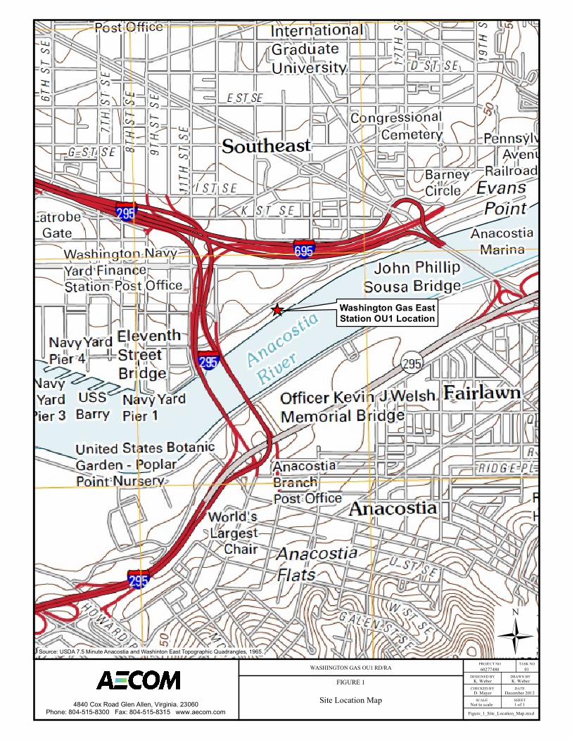
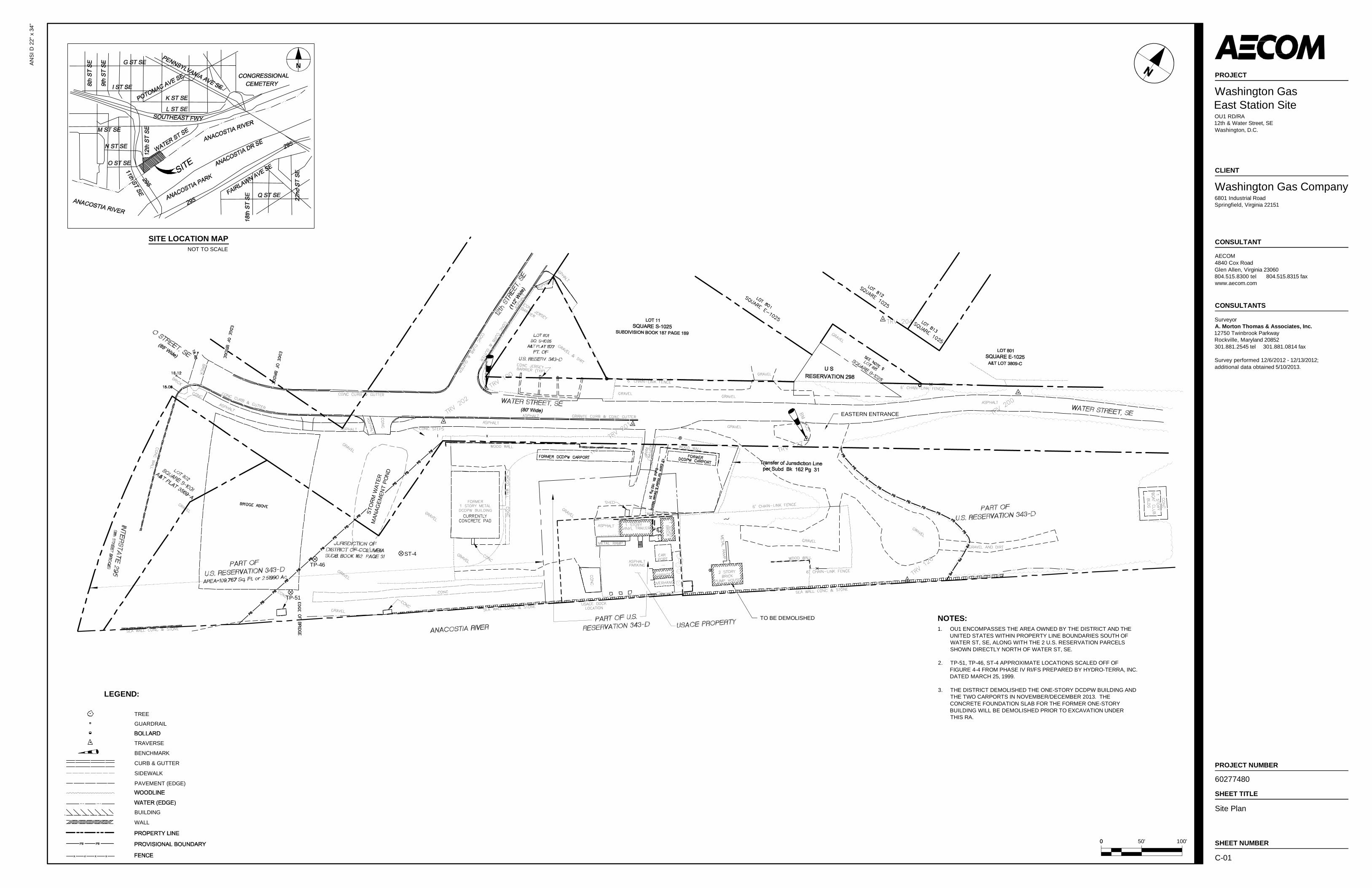
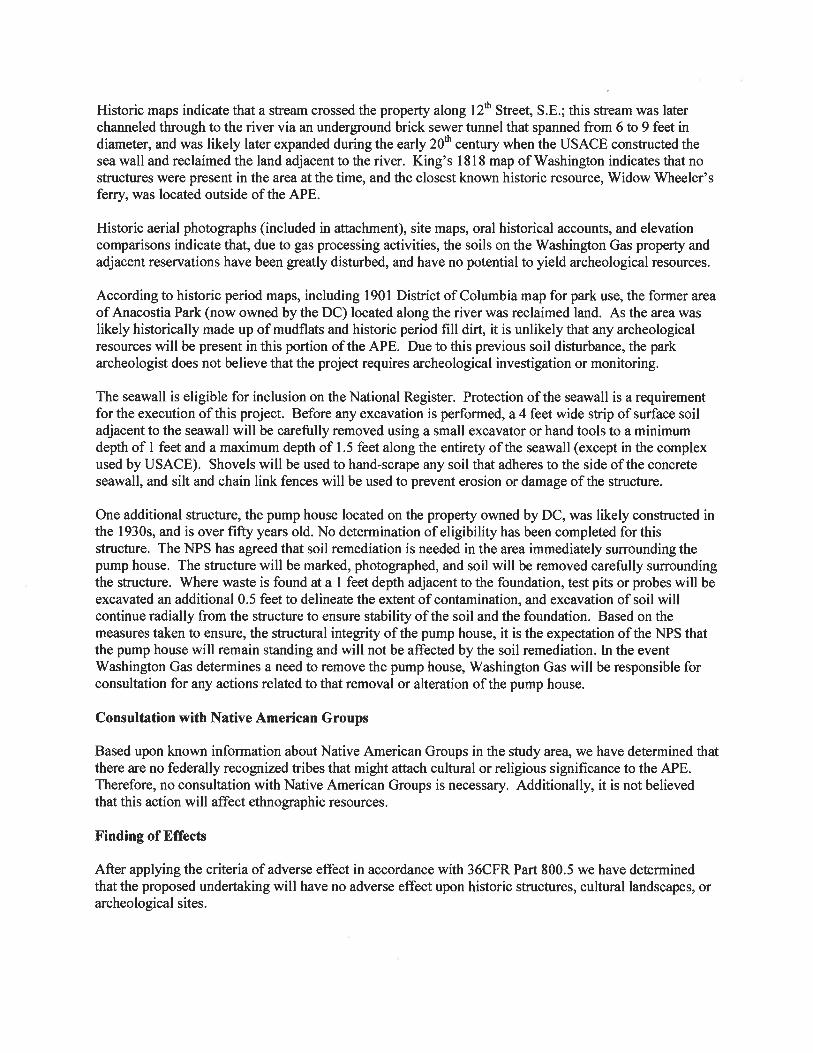
AECOM has prepared this Remedial Design/Remedial Action (RD/RA) Work Plan on behalf of Washington Gas Light Company (WG) to describe the overall technical approach of the RD/RA for Operable Unit 1 (OU1) at the WG East Station site (the Site) located at 12th and Water Streets, SE, Washington, DC, adjacent to the Anacostia River. The general Site location is shown on Figure 1, and further defined in Section IV of the Consent Decree (CD) entered by the U.S. District Court for the District of Columbia on September 26, 2012 between WG, the United States (US), and the District of Columbia (DC or District). The National Park Service (NPS) is the lead CERCLA agency in the implementation and oversight of this RD/RA, which will be conducted pursuant to and in compliance with the Comprehensive Environmental Response, Compensation, and Liability Act (CERCLA) and its implementing regulations. Pursuant to the CD, WG will conduct the OU1 RD/RA work subject to the oversight and approval of NPS, in consultation with the District.
OU1 is defined in Section IV of the CD and comprises the surface and subsurface soils of the property owned by the District and the property owned by the United States and managed by the U.S. Army Corps of Engineers (USACE), as generally depicted by the Site Map incorporated as Appendix D of the Consent Decree and shown on Drawing C-01. The primary portion of OU1 is bounded by Water Street SE to the north, the Anacostia River to the south, the tree line on the eastern side of the property, and the west side of the westernmost portion of the former 11th Street bridge (Welsh Memorial Bridge), as defined in the CD. OU1 also includes two areas north of Water Street SE, a triangular-shaped area north of the eastern entrance to the primary OU1 area defined on property maps as Reservation 298, and a second triangular shaped area at the intersection of 12th and Water Street SE defined as Reservation 343D. A more detailed description of the excavation boundaries is provided in Section 6.1.
The following drawings are included with this Work Plan:
• C-01 Site Plan
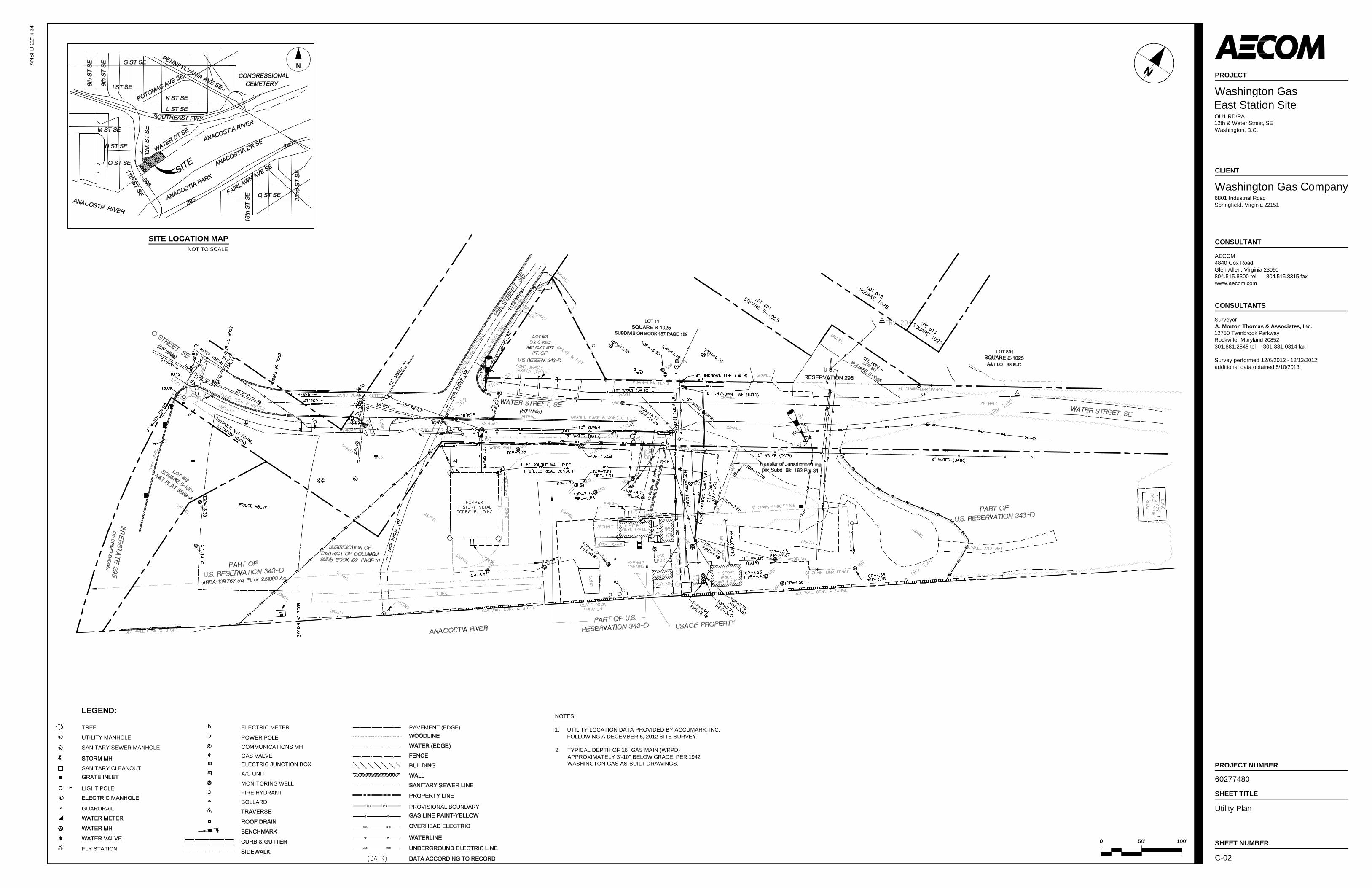
• C-02 Utility Plan
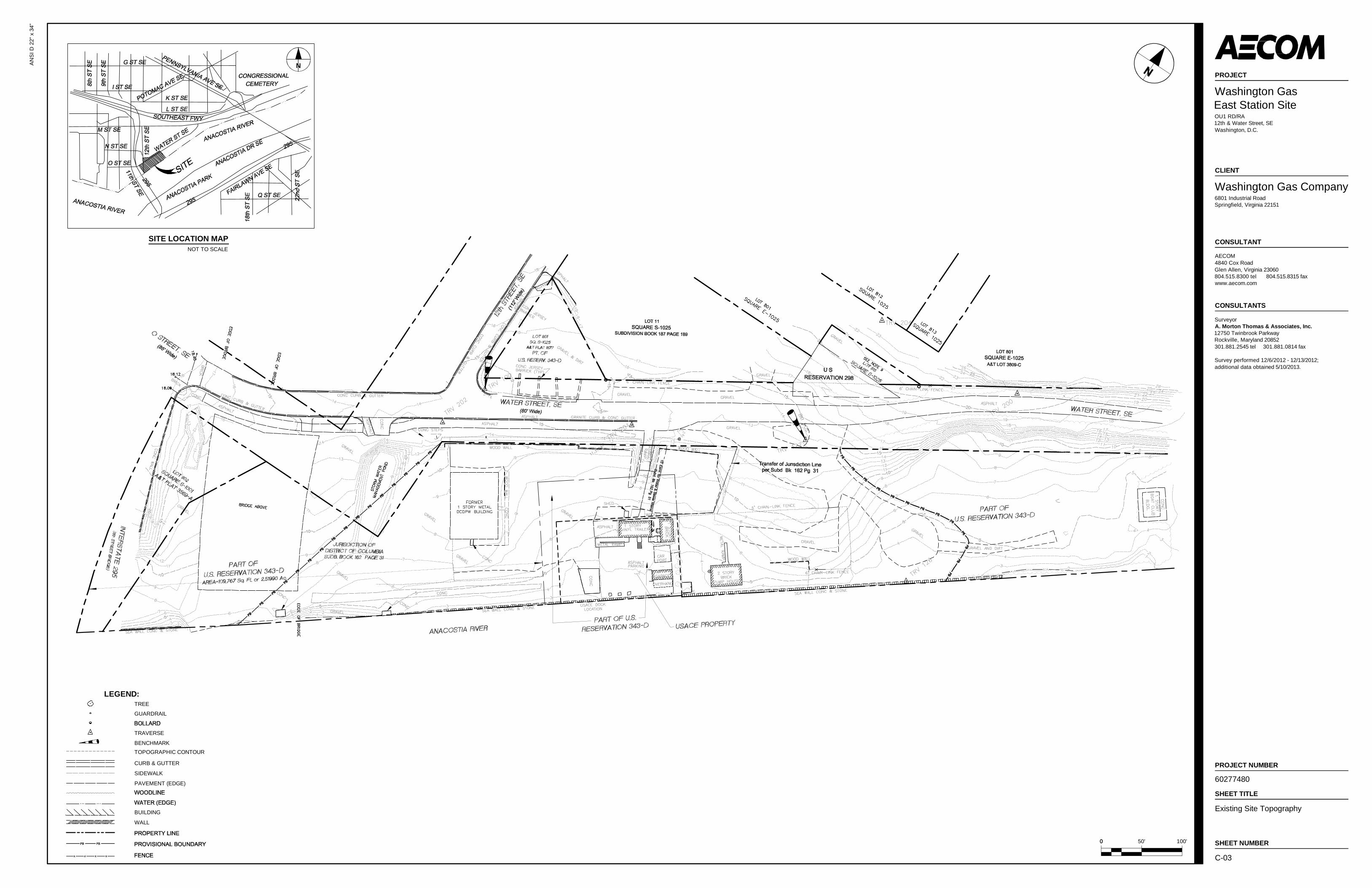
• C-03 Site Topography
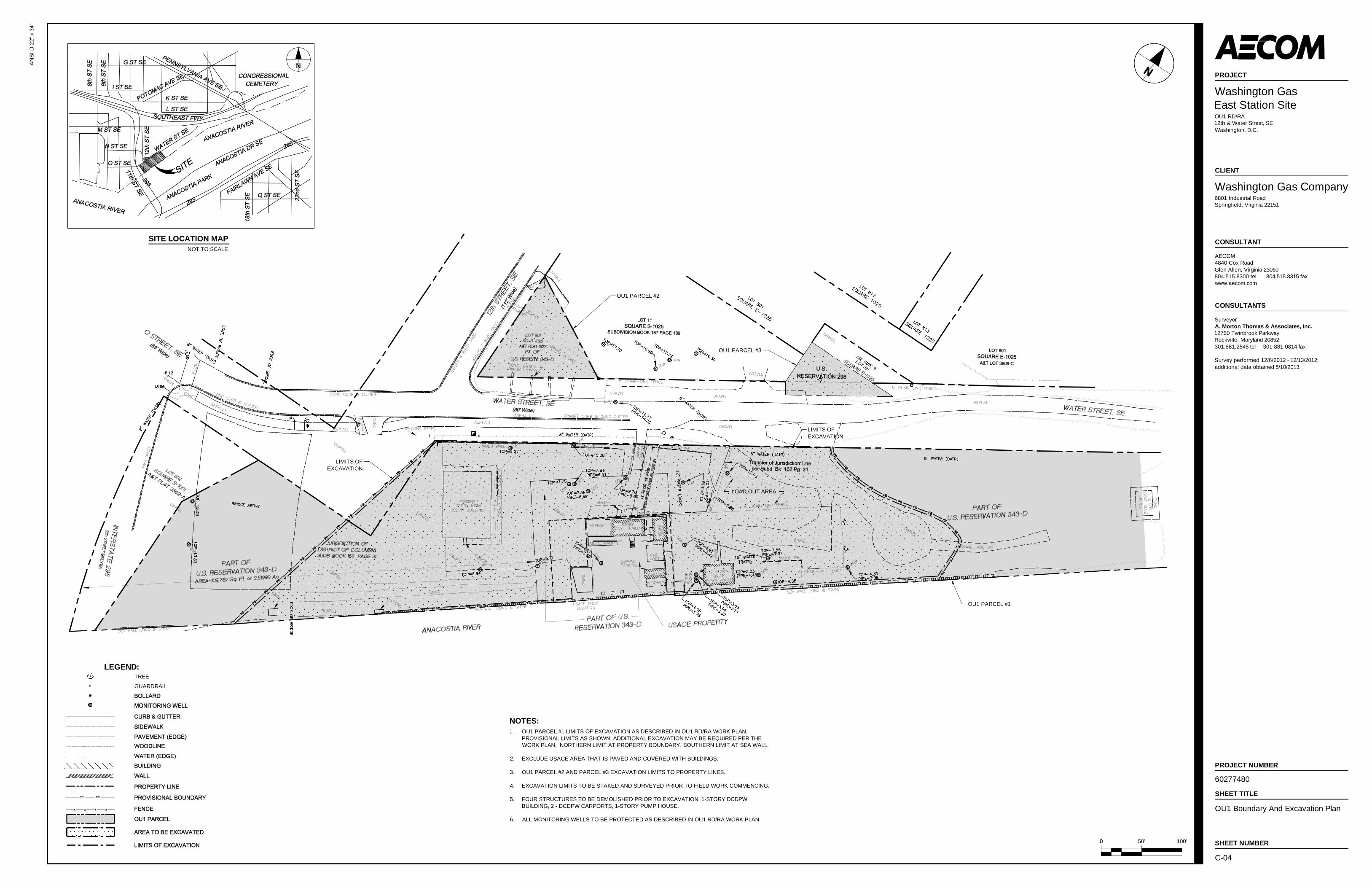
• C-04 OU1 Boundary and Excavation Plan
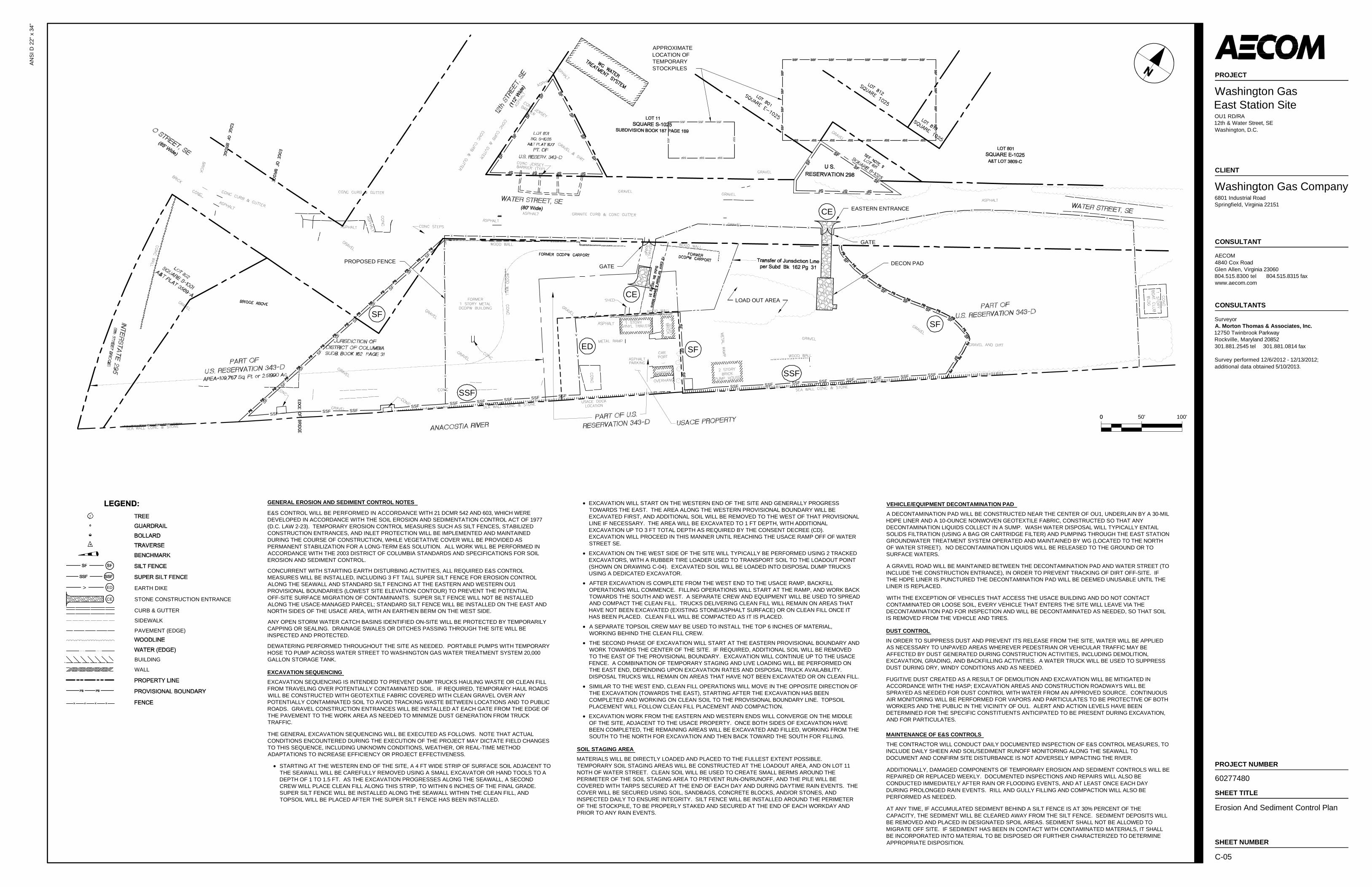
• C-05 Erosion and Sediment Control Plan
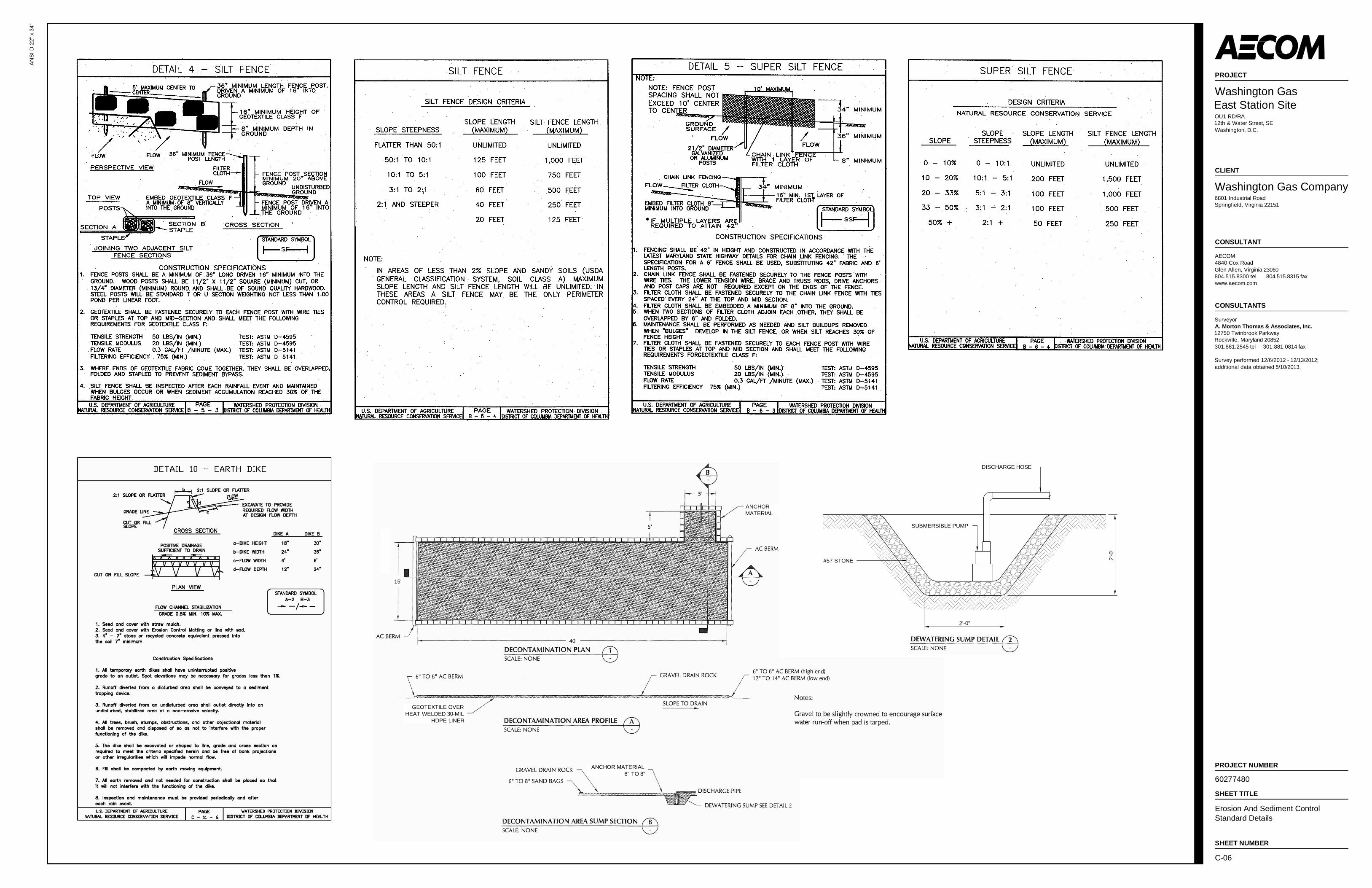
• C-06 Erosion and Sediment Control Standard Details
• C-07 Grading Plan
• C-08 Grading Tables
The area between the one-story DCDPW building and the bridge abutments was resurveyed in May 2013, and the drawings have been updated accordingly.
For definition purposes throughout this document and the companion OU1 planning documents, the term “Site” is used, consistent with the definition in the CD, to mean “any area where hazardous substances released at or from the Washington Gas East Station Property have come to be located. The Site includes OU1, OU2, and the Washington Gas-Owned Soils.” The term “OU1” is used as
AECOM Washington Gas OU1 RD/RA Work Plan – East Station Site
September 2014
1-2
defined in the paragraph above, while “site” with a lower-case “s” is used as a generic term when referencing the work site (e.g., “site preparation”, “site safety”).
The CD incorporates NPS’s August 2006 Record of Decision (ROD) for the Site, which defines the Remedial Action Objectives (RAOs) as the following:
1. Prevention of exposure of Site users and biological receptors to contaminated soils and other media,
2. Remediation of the contaminants or contaminated media to create Site conditions that result in acceptable levels of risk to Site users and biological receptors, and
3. Prevention of the release of contaminants to off-site media.
In summary, the objective of the OU1 RA is to prevent unacceptable risks to employees, visitors, construction/landscape/utility workers, and ecological receptors. The RA also is expected to reduce or eliminate contaminant migration to the Anacostia River via runoff and soil erosion. The RAOs will be satisfied by achieving the Performance Standards outlined in the CD SOW and discussed in Section 3 of this Work Plan.
The remedy will generally include the removal and off-site disposal of all surface soils throughout OU1 (defined as the top 1 foot [ft] below existing grade), and the removal and off-site disposal of subsurface soils (as much as 3 ft below existing grade) where signs of coal-tar or manufactured gas (MG) wastes are observed by visual, tactile, olfactory, or photoionization detector (PID) means. Specific excavation limits and requirements are described in greater detail in Section 6.1. Following implementation of OU1 excavation and backfilling, the remedy will also include compliance monitoring and reporting, and implementation and monitoring of Institutional Controls (ICs).
The RD/RA will be performed in accordance with the CD requirements, which incorporates the ROD as Appendix A and the Statement of Work (SOW) dated December 2011 (Revised August 2012) as Appendix B. The SOW defines specific response activities and obligations that will guide the preparation of this Work Plan and the execution of the work as described herein.
1.1 Work Plan Purpose and Scope
The purpose of this Work Plan is to provide details on the execution of the OU1 RD/RA work, including project planning, site preparation, excavation, disposal, backfilling, revegetation, and monitoring activities. The Work Plan also presents information on project organization and schedule.
Fieldwork activities described in this Work Plan will be performed in accordance with a Construction Quality Assurance Plan (CQAP) and a Project Operation Plan (POP) prepared in conjunction with this Work Plan. The POP incorporates three documents: a Site Management Plan (SMP), a Sampling and Analysis Plan (SAP), and a Health and Safety Plan (HASP). The SMP describes management procedures with regard to OU1 access, site appearance, security, safety, management responsibilities, waste management and disposal, and data management. The SAP consists of two parts: (a) a Field Sampling Plan (FSP) that provides detailed guidance for all field work by defining in detail the sampling locations and the sampling and data gathering methods to be used; and (b) a Quality Assurance Project Plan (QAPP) that describes quality assurance and quality control protocols necessary to achieve Data Quality Objectives (DQOs) dictated by the intended use of the data, including the Performance Standards as specified in the CD. The HASP specifies necessary procedures to ensure safety of Site workers, NPS and District representatives, and the public during the OU1 RA. Procedures for quality assurance and control during construction activities are detailed in the CQAP. Additionally, an Air
AECOM Washington Gas OU1 RD/RA Work Plan – East Station Site
September 2014
1-3
Monitoring Plan (AMP) provides measures for ensuring the protection and safety for construction workers on-site and the surrounding public. These documents are all provided under separate cover.
Upon approval of this Work Plan by NPS, after review and comment by the District, WG will implement the activities authorized by this document. The areas of excavation may be adjusted or expanded during the course of the RA as described in Section 6.1.
The construction remediation work described within this Work Plan, the SMP, and other OU1 project documents may require that changes be made in the document in an expedited manner when unknown or unexpected conditions arise. As such, the SMP will be a living document, with changes able to be made via addenda (in memorandum format) and in compliance with the requirements outlined in the CD and SOW, following a brief discussion between WG, AECOM, NPS, and District representatives, with other personnel involved as needed. During the discussion, NPS will notify WG if written approval to changes will be required before an action proceeds.
1.2 Work Plan Organization
This RD/RA Work Plan is organized into the following sections:
AECOM Washington Gas OU1 RD/RA Work Plan – East Station Site
September 2014
This page intentionally left blank
AECOM Washington Gas OU1 RD/RA Work Plan – East Station Site
September 2014
2-1
2.0 Site Background and Setting
2.1 Site Description
The East Station Site is the location of a former manufactured gas (MG) facility which operated from 1888 to 1983. Drawing C-01 shows a layout of the East Station Site, including the boundaries of the parcels described below, based on surveying and property research performed by A. Morton Thomas & Associates, Inc. (AMT) of Rockville, Maryland, in December 2012 and updated in May 2013. WG maintains ownership of the property north of Water Street SE, with the exception of the two parcels described below. The District owns three of the four parcels in the approximately 4.5 acre property defined as OU1, as shown on Drawing C-01. The four parcels are described as follows; referenced features are noted on Drawing C-01:
• Approximately 3.85 acres of property located south of Water Street SE between Water Street SE and the Anacostia River, in the 1100 to 1300 blocks of Water Street SE, is owned by the District.
• The United States owns and USACE manages approximately 0.35 acres surrounded by the District-owned 3.85 acres. The USACE property was not transferred to the District.
• Reservation 298 is a 0.1-acre triangular-shaped parcel north of the eastern entrance to the primary OU1 area, on the northern side of Water Street SE. This parcel, owned by the District, is fenced and is used by WG for staging equipment.
• A 0.2-acre triangular-shaped area at the northeastern intersection of 12th and Water Streets SE, which is part of Reservation 343D (Lot 801, as shown on Drawing C-01), is owned by the District. This fenced-in area was used by the DC Department of Transportation (DDOT) as a staging area for 11th Street Bridge construction until May 29, 2013, when it was cleared of all construction material.
The area south of Water Street SE is currently used/occupied by several different entities:
• The westernmost portion of the property contains a bridge abutment for the new northbound 11th Street Bridge spans. As part of the bridge construction, excavation for a new stormwater management pond was initiated by DDOT but not completed in this area. The former 11th Street (Northbound) Bridge abutment was partially located within the provisional western boundary of OU1, and there are provisions for potential additional surface and subsurface excavation to the west as defined in Section 6.1.
• Immediately to the east of the bridge abutments, the primary portion of OU1 has historically been used by the DC Department of Public Works (DCDPW). The one-story DCDPW building and the two carports adjacent to Water Street SE were removed by the District in late November/early December 2013. The concrete foundation and related footers for the single-story building will be demolished by WG prior to initiation of the RA work on OU1. The area is fenced with a gate that is controlled by USACE. This area is primarily gravel-covered and is bounded on the north by a steep slope up to Water Street SE. The slope is grass-covered and is supported at the bottom by a timber retaining wall.
• The USACE-managed property is a fenced area within the DCDPW area, consisting primarily of paved parking areas and small support buildings. A dock adjacent to the fenced area is
AECOM Washington Gas OU1 RD/RA Work Plan – East Station Site
September 2014
2-2
used for collecting and staging driftwood that USACE pulls from the river. Access to the USACE facility is provided through a gate in the fence off of Water Street SE, at which a paved ramp leads down to the USACE facility. Safe access for USACE personnel must be maintained throughout this project.
• A fenced area immediately to the east of the USACE property contains the former WG pump house, which may be demolished as a separate activity from the CERCLA response action, in preparation for this RA, if WG receives a Raze Permit from the District Department of Consumer and Regulatory Affairs (DCRA) and approval from the DC State Historic Preservation Office (SHPO). WG controls access to the locked gate for this area, although the property is owned by the District.
• An access driveway off of Water Street SE extends to the seawall at the eastern side of OU1; the curved tree line at the edge of this driveway is the provisional eastern boundary of OU1, but there are provisions for potential additional surface and subsurface excavation to the east as defined in Section 6.1. This area provides public access to the river, although it frequently has been used as an unauthorized dumping ground for household and construction wastes.
• The wooded portion of land on the eastern side of OU1, between the tree line and the adjacent property leased by the Washington Powerboat Club, is part of OU1 but is beyond the provisional eastern boundary and will be excavated only if MG wastes are observed, as described in Section 6.1.
2.2 Site History
The majority of OU1 was created from fill prior to 1912, along with fill from dredging operations conducted between 1908 and 1919. The seawall was constructed by dredging a trench into the soft sediments of the river bottom; the trench was filled with boulders and crushed rock and allowed to settle until stable at the approximately low tide elevation. The seawall was capped with concrete in the area of the Site. The fill behind the seawall consists of dredge spoils and wastes, including MG waste, demolition debris, rock, gravel, ash and cinders, and soil.
Manufactured gas was produced at the East Station facility continuously from 1888 to 1948, and intermittently until 1983. The plant was closed in 1983, and demolition of the MG buildings, holders, tanks, and other facilities proceeded until 1986. The MG-related aboveground oil storage tanks on the portion of the Site north of Water Street SE were removed in 1997.
Historical reports show that byproducts of the MG operations were occasionally placed as fill on the Site, including residual products from the cleaning of coke filter beds, tar that was mixed with solid waste, and wood chips contaminated with absorbed tar and complex cyanides. The thickness of the fill has been observed between 1 ft and 13 ft below existing grade, with an average of approximately 8 ft of fill above the underlying natural silt layer. Leakage of oil from underground pipelines on the WG property and the adjoining property to the east are also potential sources of petroleum contamination on the Site.
The seawall is porous enough to allow tidal flows of river water into and out of the Site. However, a series of pumping wells has been installed by WG to reduce the flow of groundwater off-site to the river.
2.3 Area Description - General Land Use and Demography
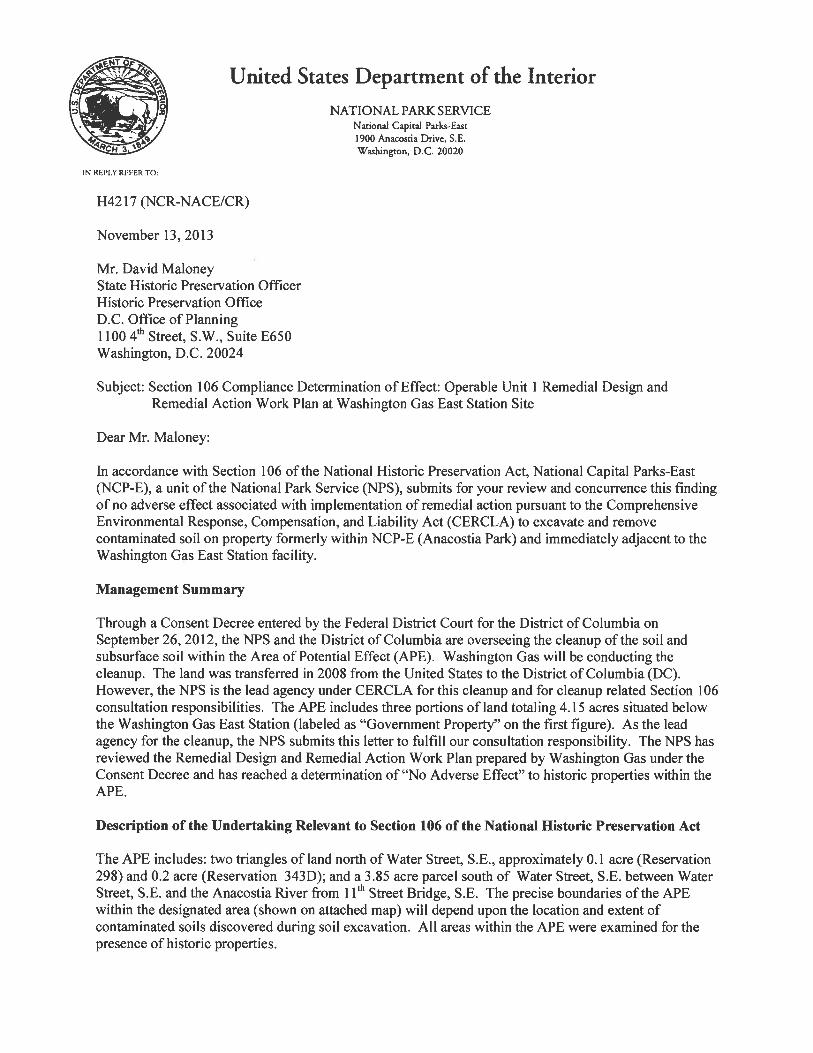
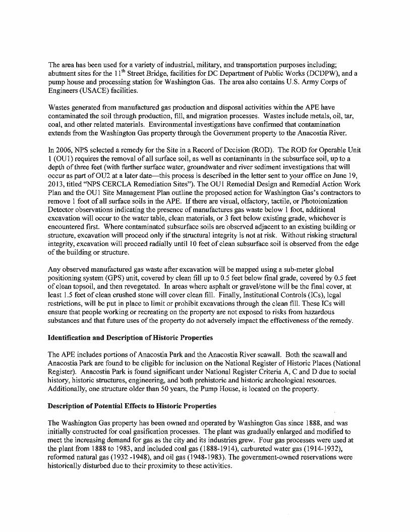
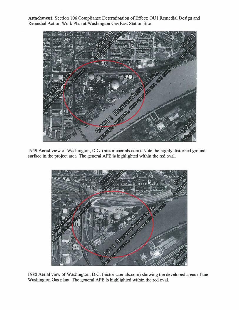
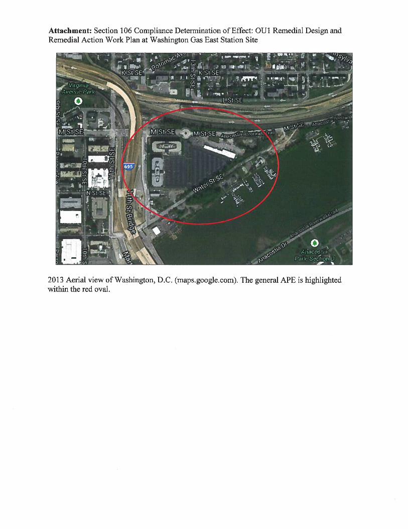
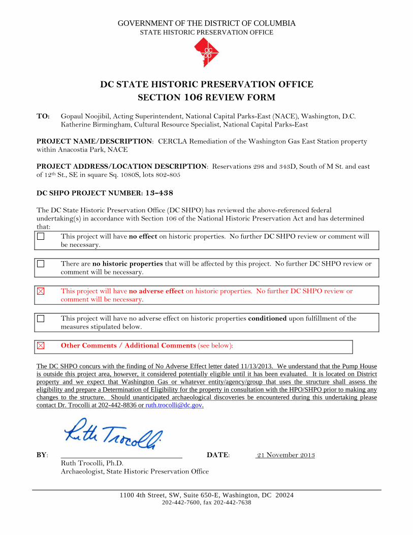
The Site is located within a major city in an area with limited access to the river. A number of surrounding properties are used for recreational purposes (e.g., boating, fishing). The seawall and Anacostia Park are both eligible for inclusion on the National Register of Historic Places due to age and historic significance. The NPS submitted a letter to the DC SHPO on November 13, 2013 (included as
AECOM Washington Gas OU1 RD/RA Work Plan – East Station Site
September 2014
2-3
Attachment 1), stating that “the proposed undertaking will have no adverse effect upon historic structures, cultural landscapes, or archaeological sites.” The DC SHPO provided concurrence to the no adverse effects determination on November 21, 2013 (also included in Attachment 1). The concurrence specifically excludes the pump house, which WG is addressing in conjunction with the raze permit (reference Section 4.1).
The WG property north of Water Street SE has been redeveloped with two large office buildings and associated parking lots. WG maintains offices and groundwater treatment equipment in an older two-story building north of Water Street SE, along with a vacant facility that was formerly used for fueling vehicles with compressed natural gas. Additional commercial development is proposed for the East Station property.
The closest residential area is approximately 1,000’ north of the Site, across a rail and interstate highway corridor. Land uses immediately to the east of the Site are recreational, with the property used by several boat clubs and the Anacostia Community Boathouse Association. At the eastern end of the Site, immediately east of the eastern provisional boundary, is property formerly used by ST Services/ Steuart Petroleum, which imported fuels by barge and pipeline from a pier (since removed) immediately east of the eastern provisional boundary of OU1. There were reportedly pipes running from the ST Services facility north of Water Street SE to a dock/pier on the Anacostia River, crossing the OU1 site approximately at the tree line at the eastern provisional boundary.
The 11th Street Northbound and Southbound (Welsh Memorial) Bridge abutments are located on or adjacent to the western portion of the Site. The Washington Navy Yard, located on the river west of the 11th Street Southbound (Welsh Memorial) Bridge, is a Navy base and former shipyard managed by the Department of Defense (DoD). Part of the Navy Yard has been sold and redeveloped and currently contains federal offices and housing. Additional parkland and an interstate highway are located across the tidal portion of the Anacostia River, which is approximately 760 ft wide in this area.
Following RD/RA actions, the Site is planned for use as a connected part of the Anacostia Riverwalk Trail system to provide public access to the river, and will be traversed by a bicycle/walking path parallel to the river. USACE plans to continue using its current facility as an operating base to remove driftwood from the Anacostia and Potomac Rivers.
2.4 Historical Investigations and Remedial Actions
A summary of historical environmental investigations conducted on the East Station Site by WG is presented in Table 1:
Table 2-1 Historical Environmental Investigations
Title Author Date Preliminary Contamination Investigation (Phase I) Hydro-Terra, Inc. 1983
Contamination and Land-Use Study (Phase II) Hydro-Terra, Inc. 1989
Additional Sampling and Ground-Water Recovery System Design (Phase III) GeoTrans 1991
Site Investigation for WMATA Facility Engineering-Science 1994
Site Inspection of NPS/East Station Site Ecology and Environment, Inc. 1995
Additional Remedial Investigation and Feasibility Study (Phase IV) Hydro-Terra, Inc. 1999
Assessment of Health Risks to Utility and Landscape Workers on National Park Service Property South of East Station
Hydro-Terra, Inc. 2002
AECOM Washington Gas OU1 RD/RA Work Plan – East Station Site
September 2014
2-4
The investigations show that the Site primarily consists of fill containing dredge spoils and industrial waste from historic WG operations along with miscellaneous waste from unknown sources. The primary contaminant of concern (COC) is coal tar, which contains polycyclic aromatic hydrocarbons (PAHs); volatile organic compounds (VOCs), primarily benzene; cyanide; and metals, including arsenic, beryllium, and lead. Shallow soil (fill), deeper soil (sand and gravel aquifer beneath the natural silt that is under the fill), and groundwater are impacted with coal tar and other constituents.
AECOM has compiled and reviewed approximately 50 boring logs created during the drilling and installation of on-site monitoring wells and the descriptions of approximately 80 test pits and test borings throughout the OU1 footprint. These logs and descriptions were developed by previous consultants and provide detailed reports of subsurface conditions across the Site. In general, the 0 to 3 ft below grade surface (bgs) interval consists of fill including, but not limited to, brick, gravel, coal, sand cinders, glass, and organics (roots). There are multiple references to ash, cinders, wood chips, sponge, tar, and coal ash, all of which are potentially indicative of MG materials. The fill materials are generally loose in nature and the soil varies from dry to moist. The descriptions of contamination vary from non-detectable to visible coal tar. Based on the available descriptions, subsurface (up to 3 ft depth) MG waste appears to be prevalent throughout much of OU1 within the provisional boundaries.
This Work Plan only addresses surface and subsurface soils, up to a maximum of 3 ft below existing grade. A separate activity under this CD is to perform an RI/FS for OU2, defined as “groundwater, surface water, and sediments of the Anacostia River where hazardous substances released at or from the Washington Gas East Station Property have come to be located.” The OU2 RI/FS, which is also in the planning stages concurrent with the OU1 RD/RA, will investigate the nature and extent of releases of hazardous substances in groundwater, surface water, and sediments at the Site, and develop and evaluate options for remedial action as needed.
WG performed various remedial actions at the Site before the NPS CERCLA process began. The majority of these actions are related to the groundwater pump-and-treat system designed to remove contaminants from the groundwater and to reduce the flow of groundwater from the Site to the river. In addition, WG periodically pumps liquid coal tar from wells in which it accumulates. These activities have been documented in the ROD and will be described in greater detail in the OU2 RI/FS Work Plan. The recovery wells and related piping, along with the extensive network of monitoring wells throughout the Site, will be protected during the excavation and restoration activities during the OU1 RA.
AECOM Washington Gas OU1 RD/RA Work Plan – East Station Site
September 2014
3-1
3.0 Performance Standards
This section summarizes the Performance Standards for the OU1 RD/RA project, in accordance with Section 5.0 of the CD SOW. Section 6 of this Work Plan provides greater detail regarding the proposed extent of contaminant removal.
3.1 Removal of Contaminants
The CD/SOW requires that soils be removed in accordance with the following Performance Standards:
1. All OU1 surface soils to a 1 ft depth (except on the east end of the site under the “hardwood canopy” to the east of the eastern provisional boundary, and on the west end beyond the western provisional boundary as shown on Drawing C-01, which will be removed upon evidence of MG residuals as described in Section 6.1; and those surface soils that were previously replaced, unless they contain evidence of tar).
2. OU1 subsurface soils (between 1 ft and a maximum depth of 3 ft below existing grade) where visual, olfactory, tactile, or PID observations indicate the presence of MG waste as described in Section 6.1. The maximum excavation depth will be the water table, clean materials, or 3 ft below existing grade, whichever is encountered first.
3. Where contaminated subsurface soils are observed adjacent to an existing building or structure, excavation will proceed only if the structural integrity is not at risk. Without risking structural integrity, excavation will proceed radially until 10 ft of clean subsurface soil is observed from the edge of the building or structure, as detailed in Section 6.1.
WG shall excavate in accordance with the SOW requirements as described in Section 6.3. However, in areas where MG wastes are not observed below 1 ft deep, WG reserves the option to excavate to a 3 ft depth if it determines it is more efficient to do so. WG will notify NPS and its On-Site Representative (to be designated by NPS prior to initiation of Site activities), as well as the District, about its plan for additional excavation and proceed accordingly; the horizontal and vertical limits of excavation will be mapped and included in the as-built drawings as described in Section 7.5.
3.2 Isolation of Contaminants
The following Performance Standards dictate fill, cover, and vegetation requirements:
1. Any observed MG waste remaining after the excavation will be measured for surface area, recorded by a sub-meter global positioning system (GPS) unit, mapped, covered by clean fill up to 0.5 ft below final grade, covered by 0.5 ft of clean topsoil, and then revegetated. In areas where asphalt or gravel/stone will be the final cover, at least 1.5 ft of clean crushed stone will cover clean fill. The fill and vegetated topsoil/cover will be installed to prevent erosion or subsidence after placement.
2. Clean fill and topsoil materials will meet the clean fill requirements specified by the CD SOW.
3. Revegetation will meet the following Performance Standards; the methods for NPS to quantify vegetation are detailed in the CD SOW:
a. The seed mix will be subject to NPS approval.
AECOM Washington Gas OU1 RD/RA Work Plan – East Station Site
September 2014
3-2
b. Grass and legume planting will be successful if the following Performance Standards are met in two successive years following seeding completion:
i. At least 90% of the area must be considered “Good” coverage, with 76 to 100% vegetation established.
ii. A maximum of 10% of the area must meet “Fair” coverage, with 50 to 75% vegetation.
iii. No areas classified as “Poor” (less than 50% coverage) will be acceptable.
c. If any areas fail the revegetation Performance Standards at the first yearly evaluation, a second evaluation will be performed 1 year after the failure determination or reseeding (if performed), whichever occurred later. The original grass mix or an alternative approved by NPS will be used.
d. After the second yearly evaluation, all areas not meeting the Performance Standards will be unacceptable and will be replanted as required by NPS. WG’s revegetation obligations will continue until the Performance Standards are met.
3.3 Institutional Controls
Performance Standards for ICs will be the establishment, maintenance, and enforcement (where necessary) of use restrictions for all media and areas for which ICs are required. ICs required by the CD are discussed in Section 7.8. Documentation of IC maintenance will be included in five-year review reports required by the CD. For property owned or controlled by the United States or the District, WG will design and implement ICs within the limits of their legal capabilities.
AECOM Washington Gas OU1 RD/RA Work Plan – East Station Site
September 2014
4-1
4.0 Attainment of ARARs and Substantive Permit Requirements
CERCLA provides that no Federal, State, or local permit is required for the portion of any response action conducted on-site but requires that the substantive requirements that would be contained in a permit must be satisfied. This section outlines the specific statutes or regulations for which a permit would be required but for the CERCLA permit exemption, and describes how the substantive requirements that would otherwise be established in such permits will be satisfied as the remedy is designed and implemented.
Without the CERCLA permit exemption, a project involving the activities required to implement the OU1 RA would typically be required to obtain permits for demolition, erosion and sediment (E&S) control, and stormwater discharge/management. District regulations and substantive requirements that would be contained in a permit will be addressed and adhered to during OU1 RA activities as detailed in this Work Plan.
4.1 Demolition Permit Equivalency
Demolition of the pump house, which is outside the scope of the OU1 SOW, will be performed in conjunction with the RA, if WG receives all necessary approvals and permits from the District. AECOM will follow all DCRA-specific Raze Permit requirements in the execution of that work, and will ensure that all utility services to the building are inactive prior to beginning demolition. As part of the Raze Permit, the DC SHPO must also approve the pump house demolition.
4.2 Erosion and Sediment Control
Erosion and sediment control will be performed in accordance with 21 DC Municipal Regulations (DCMR) 542 and 603, which were developed in accordance with the Soil Erosion and Sedimentation Control Act of 1977 (D.C. Law 2-23). Temporary erosion control measures such as silt fences, stabilized construction entrances, and inlet protection will be implemented and maintained during the course of construction, while vegetative cover will be provided as permanent stabilization for a long-term E&S solution. All work will be performed in accordance with the 2003 District of Columbia Standards and Specifications for Soil Erosion and Sediment Control. Temporary E&S measures are shown on the E&S Controls Plan, Drawings C-05 and C-06, and long-term measures are described in greater detail in Section 7.8. As described in the SMP, during the remedial construction work AECOM will conduct daily documented inspection of erosion and sediment control measures detailed in the Erosion and Sediment Control Plan (Drawing C-05). Additionally, AECOM will repair or replace damaged components of temporary erosion and sediment controls weekly. Documented inspections and repairs will also be conducted immediately after rain or flooding events, and at least once each day during prolonged rain events. The inspections will include daily sheen and soil/sediment runoff monitoring along the seawall to document and confirm site disturbance is not adversely impacting the River.
4.3 Storm Water Construction Permit
Stormwater control will be performed in accordance with 40 Code of Federal Regulations (CFR) 122.26 and 20 DCMR 6208 and 6209; all work will also be performed in accordance with the Soil Erosion and Sedimentation Control Act of 1977 (D.C. Law 2-23). Activities will comply with the substantive requirements of the National Pollutant Discharge Elimination System (NPDES) General Permit for
AECOM Washington Gas OU1 RD/RA Work Plan – East Station Site
September 2014
4-2
Construction Activities. All work will be performed in accordance with the 2003 DDOE Stormwater Guidebook, which provides design criteria to comply with the DC Storm Water Management Regulations, DCMR Title 21, Chapter 5.
4.4 Air Emissions Control
The National Primary and Secondary Ambient Air Standards, 40 CFR Part 50, establish standards for ambient air quality to protect public health and welfare during activities such as earthwork during remediation projects. Section 5.5 of this Work Plan describes the air monitoring procedures to be implemented to ensure compliance; the HASP also describes air monitoring and corrective actions.
District regulation 20 DCMR Chapter 605, Control of Fugitive Dust, requires the control of dust from earthmoving and demolition activities. Appropriate measures will be taken to control dust particulates, as described in Section 7.4.9 and in the HASP. All work will also be performed in accordance with the Soil Erosion and Sedimentation Control Act of 1977 (D.C. Law 2-23).
20 DCMR Chapter 900 prohibits idling of parked vehicles for more than 3 minutes, so all vehicles will be required to turn off their engines if they will be sitting for 3 minutes or more. 20 DCMR 901 requires that vehicles be equipped to prevent the escape of a trail of visible fumes or smoke for more than 10 consecutive seconds. 20 DCMR 903 prevents the release of odors or other nuisance air pollutants, which will be addressed by air monitoring as described in Section 5.5.
4.5 Noise Control
20 DCMR 2701 and 2802 regulate noise levels at construction sites. The closest residential area is approximately 1,000 ft away, and major bridge construction has been ongoing in the area for the last several years. Noise control provisions for this project are discussed in Section 10.4.
4.6 National Historic Preservation Act
The seawall and Anacostia Park are both eligible for inclusion on the National Register of Historic Places due to age and historic significance. The NPS submitted a letter to the DC SHPO on November 13, 2013 (included as Attachment 1), stating that “the proposed undertaking will have no adverse effect upon historic structures, cultural landscapes, or archaeological sites.” The DC SHPO provided concurrence to the no adverse effects determination on November 21, 2013 (also included in Attachment 1). The concurrence specifically excludes the pump house, which WG is addressing in conjunction with the raze permit (reference Section 4.1). Measures for protecting the integrity of the seawall are described in Section 7.3.5. The DC SHPO will be notified if unanticipated archaeological discoveries are encountered during work for OU1.
4.7 Endangered Species Act
AECOM has solicited consultation from Mr. Trevor Clark of the U.S. Fish and Wildlife Service (USFWS), Chesapeake Bay Field Office (e-mail sent May 7, 2013). According to the USFWS, there are no federally proposed or listed endangered or threatened species known to exist within the project area. An “Online Certification Letter” was received on May 9, 2013, confirming the review of the OU1 Site. A copy of this letter is included in Attachment 2.
Additional Federal ARARs that may be applicable to this project are listed below. These conditions are not anticipated to be present at the Site during this RA, but in the event that findings or events make them applicable, all regulations and requirements will be followed.
AECOM Washington Gas OU1 RD/RA Work Plan – East Station Site
September 2014
4-3
• Migratory Bird Treaty Act – several large trees will be required to be cut down to facilitate this RA; tree cutting will be performed between August 1 and March 15 to avoid nesting season.
• Coastal Zone Management Act – the RA is not anticipated to affect the water quality or wildlife in this area.
AECOM Washington Gas OU1 RD/RA Work Plan – East Station Site
September 2014
This page intentionally left blank
AECOM Washington Gas OU1 RD/RA Work Plan – East Station Site
September 2014
5-1
5.0 OU1 RD/RA Project Plans
This section outlines the RD/RA project plans that supplement and support this Work Plan, provides the framework of each plan, and describes how they interrelate with this Work Plan. Additional elements that do not have plans as separate documents but are considered part of this Work Plan are also discussed in this section, including contingency planning. A separate Air Monitoring Plan (AMP) has been developed for the ambient fence line air monitoring program, to ensure there is no off-site migration of contaminants that would represent any potential exposure concerns to the adjacent public, including USACE personnel working adjacent to or within the OU1 Site.
The following plans have been developed in conjunction with this Work Plan to guide the execution of the OU1 RD/RA work:
• Project Operation Plan (POP), which incorporates:
o Site Management Plan (SMP)
o Sampling and Analysis Plan (SAP), with 2 parts:
Field Sampling Plan (FSP)
Quality Assurance Project Plan (QAPP)
o Health and Safety Plan (HASP)
• Air Monitoring Plan (AMP)
• Construction Quality Assurance Plan (CQAP)
A brief description of each plan element and how it relates to this Work Plan is provided below.
5.1 Site Management Plan
The SMP provides details on Site access, appearance, security, management structure, waste management, safety procedures, contingency planning, and data management. Site access is primarily governed by Section VIII of the CD, as well as the access agreement included as Appendix E of the CD. The SMP also outlines procedures for keeping NPS and the District informed of access requirements and any issues that may arise.
5.2 Sampling and Analysis Plan
The SAP, which includes the FSP and the QAPP, outlines DQOs, field sampling and sample management procedures, analytical requirements, data management, and quality assurance (QA) for sampling and analysis. The field sampling to be performed under this RA consists of four distinct activities:
1. Sampling excavated soils for waste characterization purposes in order to properly dispose of the impacted soils at an off-site facility,
2. Screening the in situ soils in the excavation between 1 and 3 ft using a PID and by visual, olfactory, and tactile means;
AECOM Washington Gas OU1 RD/RA Work Plan – East Station Site
September 2014
5-2
3. Sampling imported fill to assure that all imported materials meet the clean fill standards as required by the CD, to include both clean fill and topsoil; and
4. Compaction testing using a nuclear density gauge to verify that clean fill and topsoil have been compacted appropriately.
The SAP discusses procedures for nuclear density gauge testing to verify that compaction of clean fill and topsoil meets the requirements in Section 7.7. It also describes the use of the PID as a tool during subsurface excavation and post-excavation mapping to help identify the presence of MG waste.
5.3 Health and Safety Plan
The HASP, which was developed in accordance with OSHA 29 CFR 1910.120, provides a general description of the levels of personal protection and safe operating guidelines expected of each employee associated with the OU1 RD/RA. The HASP also identifies chemical and physical hazards known to be associated with the WG-managed activities at the Site. All work will be performed in accordance with the HASP, all personnel working on the Site will have read and will be familiar with the HASP, and a Site Safety Officer (SSO) will be on-site full-time during execution of the work.
5.4 Air Monitoring Plan
Air monitoring is discussed in detail in Section 4.5 of the HASP and in the AMP. In general, WG will provide personnel and instrumentation to monitor dust and VOC emissions quantitatively and odors qualitatively, in order to protect the public and nearby workers (including USACE employees), as well as workers on the Site. The human health risk assessment in the 1999 RI/FS specifically identified hazards to heavy equipment operators due to inhalation of manganese-laden particulates.
The following specific activities will be performed under this task:
• Install three stationary VOC monitors (10.6 electron volt [eV] PIDs) and three stationary dust monitoring instruments measuring particulate matter less than 10 micrometers in size (PM10). Monitoring locations will be upwind on the fence Site boundary line, downwind on the Site boundary line, and the location nearest the Site construction activity adjacent to the USACE facility. When there are no USACE personnel at the Site, the third monitor may be used to address other areas depending on site conditions.
• Operate one set of handheld instruments, to include a PID for VOC measurement and a particulate monitor for PM10 measurements, on-site for real-time perimeter and employee safety monitoring. The PID will be a 10.6 eV Multi-RAE device with four-gas detection, including Lower Explosive Limit (LEL), oxygen (O2), hydrogen sulfide (H2S), and carbon monoxide (CO).
• Operate an additional 10.6 eV PID to help determine extent of subsurface excavation, as well as potential remaining MG waste during post-excavation GPS mapping.
• Collect required background air monitoring data prior to the start of field activities.
• Collect continuous 15-minute average VOC and PM10 readings at two stationary Site boundary fence-line locations (one upwind and one downwind) and adjacent to the USACE facility during excavation and loading activities.
• Collect instantaneous VOC and particulate measurements during surveys of the Site perimeter using hand-held equipment.
AECOM Washington Gas OU1 RD/RA Work Plan – East Station Site
September 2014
5-3
• Use the hand-held equipment to monitor worker exposure in the breathing zone during excavation and loading activities. Personal VOC monitors may also be used for individual equipment operators if observed concentrations warrant this level of monitoring.
• Maintain calibration and monitoring logs.
• Coordinate with the Site Supervisor (see Section 8.1.3) to activate vapor/dust/odor controls, if monitoring data exceed established action levels.
• Download data from the monitoring stations on a daily basis and provide results to NPS and the District by 10 AM the following business day.
• Analyze and present the air monitoring data in the site closure report upon completion of the remediation.
• Maintain at least one back-up particulate monitor and one VOC monitor, in addition to the three stationary instruments being used daily, so a failing instrument can be replaced without a significant gap in data collection.
• Establish a protocol for air monitoring requirements during and immediately following rain and/or snow events.
Site-specific alert (total VOCs 1 ppm above background for 15-minute average, particulates 100 micrograms per cubic meter [µg/m3]) and action (total VOCs 5 ppm above background for 15-minute average, particulates 150 µg/m3) goals have been established and appropriate actions will be taken when these limits are exceeded, including stoppage of work, personal protective equipment (PPE) upgrades, and engineering controls (e.g., covering the source with soil, suppressive foam, water, or odor suppressing agents). The action goals and corrective actions are described in greater detail in the AMP.
5.5 Construction Quality Assurance Plan
The CQAP was developed, in accordance with USEPA guidelines, to describe the approach to quality assurance and the measures to be taken to determine compliance with plans and specifications through tests and systems of inspection during OU1 construction activities. Construction Quality Assurance (CQA) is defined as a planned system of activities that ensures that the remedy is constructed as specified in the design. The system includes inspections, verifications, audits, and evaluations of materials and workmanship necessary to determine and document the quality of the construction elements.
The CQA process will assure that qualified people are monitoring the progress and quality of construction. The process provides an objective overview of project progress and can help identify potential deficiencies or future problem areas during and after construction. The CQAP identifies the personnel involved in construction quality controls, their relationships, and their responsibilities; establishes QC reporting requirements; and requires that any test results, field observations, and as-built plans be compiled into a Final Report to document that construction was completed as designed and the RAOs were met.
The primary quality-controlled aspects of this project include excavation to the required depths and boundaries, soil screening for disposal, safe and appropriate management of the excavated wastes, meeting clean fill specifications, filling to match existing grades, appropriate compaction of placed soils, proper grading and revegetation, and documenting excavation limits and any remaining contaminated areas. The CQAP describes each of these elements, with sampling and inspection procedures to ensure that each element is executed as intended, with corrective actions when necessary.
AECOM Washington Gas OU1 RD/RA Work Plan – East Station Site
September 2014
5-4
5.6 Contingency Plan
Emergency action and contingency planning are described within Section 9.0 of the HASP and Section 3.11 of the SMP. This includes contingencies for serious injuries to on-site workers and such potential incidents as a chemical spill, tornado, fire/explosion, flood, or lightning strike. Emergency planning and response procedures are outlined, including spill containment, accident/incident reporting, and spill reporting. Individual responsibilities and telephone numbers for key personnel and reporting/emergency responders are also provided.
AECOM Washington Gas OU1 RD/RA Work Plan – East Station Site
September 2014
6-1
6.0 Work Plan Rationale
This section provides the rationale behind remedial design elements, including the extent of excavation and how excavation will be planned to maximize efficiency of production, procedures for identifying and verifying clean fill, procedures for invoking the clean fill flexibility language in the CD, waste characterization and disposal strategies, and revegetation procedures.
6.1 Extent of Excavation – CD Requirements
Excavation is required to include the top 1 ft of soil from the entire OU1 area, and additional excavation is required (with some exceptions) to a maximum depth of 3 ft below grade where MG wastes are observed after the first 1 ft of soil has been removed. MG wastes include tar, coke, or purifier box waste wood chips. Tar is coal tar or coal-tar-like material that is a viscous, oily, dark brown or black material that can be identified visually, tactilely with protective gloves, or by odor. Field observations to identify MG waste include visual, tactile, and/or olfactory, and can be supported with PID readings (taken at 4 inches above ground surface). Any one of these conditions will constitute the positive identification of MG waste and dictate whether additional excavation is necessary, as described below.
The areal extent of excavation boundaries is defined as follows and depicted on Drawing C-04:
1. The northern boundary of the primary OU1 area is defined as the property line along Water Street SE right-of-way.
2. The southern boundary is the landside face of the seawall along the Anacostia River.
3. The provisional western boundary of OU1 is defined in the CD as “a line … that shall extend west and north of and encompass the locations of the following pits and excavations in which tar or NAPL has been noted: TP-46, TP-51, WGL-01S, and ST-4. The initial line of excavation shall then extend north from ST-4 towards the former location of TP-57 across Water Street SE and terminate at the District property line along the south side of Water Street.” Excavation to the west between the provisional western boundary and the western Site boundary will be required if MG wastes are observed. The western Site boundary is located at the west side of the westernmost 11th Street (Welsh Memorial) Bridge.
4. The eastern provisional boundary is defined as “the tree line at the western extent of the canopy created by existing live hardwood trees and ground vegetation.” If MG wastes are found at this boundary, excavation will continue eastward concentrically in 10-foot increments until a 10 ft radius can be established around the last evidence of contamination without uncovering further MG waste.
Additional excavation will be performed in two areas north of Water Street, as follows:
• Reservation 298, a 0.1-acre triangular-shaped area north of the eastern entrance to the primary OU1 area, on the northern side of Water Street SE.
• A 0.2-acre triangular-shaped area at the northeastern intersection of 12th and Water Streets SE, which is part of Reservation 343D.
AECOM Washington Gas OU1 RD/RA Work Plan – East Station Site
September 2014
6-2
The minimum required and maximum potential excavation depths (including exceptions) are as follows, in accordance with the CD:
• A minimum of 1 ft throughout all of OU1, including the two areas north of Water Street SE.
• If MG waste is observed at the bottom of the excavation after 1 ft of material has been removed, excavation will continue in 0.5 ft lifts with a 10 ft radius around the positive identification of MG waste until no sign of MG waste is observed, to a maximum depth of 3 ft below existing grade, except beside structures and buildings (see below).
• Maximum excavation depth will be 3 ft, except in the following circumstances:
o If the groundwater table is encountered above the 3 ft maximum depth, excavation will cease at that depth.
o Where MG waste is found at a 1 ft depth adjacent to footers or foundations, test pits or probes will be excavated an additional 0.5 ft to delineate the extent of contamination. Where contamination still exists at the 1.5 ft depth, excavation will proceed laterally until a 10 ft buffer of non-impacted soil has been observed. Excavation deeper than 1.5 ft will only be required at a safe distance away from the foundation (approximately 2.5 ft).
• The USACE property will only be excavated in grassy areas; no excavation is required below pavement or structures unless there is documentation from previous excavation work that MG wastes exist at 1 ft depths.
Areas where MG waste remains, either at 3 ft depths or in areas described above as exceptions, will be located using a sub-meter GPS instrument, shown clearly on the as-built drawings with a notation to explain what type of waste remains in-place, and the coordinates will be recorded as part of the ICs for the Site.
WG proposes to meet the requirements of the CD/SOW using an excavation approach to maximize efficiency, as described in Sections 3.1 and 6.3.
6.2 Extent of Excavation – Additional Design Parameters
This section defines the expected lateral limits of the soil excavation from a practical and safety standpoint. Drawing C-03 shows the current site topography, and Drawing C-04 shows the proposed excavation boundaries for OU1.
1. The northern property boundary is located on the edge of the Water Street SE right-of-way. Based on the boundary survey performed in December 2012, and verified by markout stakes in May 2013, this property line is 1 ft north of the wooden retaining wall in the vicinity of the northwest property boundary and continues due east (as shown on Drawing C-01). Excavation will be performed up to the retaining wall between the eastern and western boundaries described below. The asphalt-covered USACE access ramp to the main gate will not be removed, as the area is built-up approximately 3 ft to 6 ft above existing grade and covered with impervious material, and will remain in place for the duration of the project and beyond to maintain USACE access.
2. For the southern boundary adjacent to the seawall, protection of the seawall and prevention of soil or other materials from entering the river must be achieved in the execution of this project. Before any other excavation is performed, a 4 ft wide strip of surface soil adjacent to the
AECOM Washington Gas OU1 RD/RA Work Plan – East Station Site
September 2014
6-3
seawall will be carefully removed using a small excavator or hand tools to a minimum depth of 1 ft and a maximum depth of 1.5 ft. This action will occur along the full length of the seawall between the western and eastern provisional boundaries, with the exception of the USACE-managed parcel. A chain link fence-supported silt fence (i.e., Super Silt fence) will be installed in accordance with manufacturer specification along the seawall during this excavation (excluding the USACE parcel except as described in bullet 4, below, for the same parcel, protection for that area is shown on Drawing C-05), providing E&S protection during earthwork activities. Shovels will be used to hand-scrape any soil that adheres to the side of the concrete seawall. Clean fill will be placed in conjunction with chain link fence-supported silt fence installation. The location of any MG waste observed at the 1.5 ft depth along this strip will be identified using GPS and included in the as-built map as part of the site closure report.
3. The seawall is continuous along the southern boundary of the Site, with the exception of approximately 70 ft of shoreline adjacent to the western provisional boundary (in the area of the former 11th Street bridge abutment). This area of the shoreline is south of the stormwater retention pond installed by DDOT during 11th Street bridge construction activities, and is currently protected by Super Silt fence. The Super Silt fence was installed as close to the eroding shoreline as possible, and will be used during OU1 excavation to demarcate the southern extent of the excavation and continue to provide protection to the river. Consistent with E&S control measures described in Section 4.2, the Super Silt fence will be inspected prior to and during excavation work, and will be repaired and maintained as necessary.
4. The only other area on the Site where the seawall is not continuous is an approximately 3 ft long gap in the vicinity of the USACE-managed property. This area will be protected in a similar manner as described in items 2 and 3 above, with the installation of Super Silt fence along this gap to prevent damage to the seawall and prevent silt or soil from entering the river. The 4 ft wide strip of surface soil immediately adjacent to the seawall will be carefully removed using a small excavator or hand tools.
5. The western Site boundary is defined in the CD/SOW as the west side of the westernmost 11th Street Bridge, but the CD also defines a provisional western excavation boundary as including the areas defined by “the following pits and excavations in which tar or NAPL has been noted: TP-46, TP-51, WGL-01S, and ST-4. The initial line of excavation shall then extend north from ST-4 towards the former location of TP-57 across Water Street.” Most of these pits were excavated in 1989, and no survey or GPS data is available to determine exact locations. The western provisional boundary is shown on the drawings consistent with the approximate location of the provisional boundary line depicted on Figure 1 of the SOW. The drawings have also been revised to reflect the changes due to 11th Street Bridge construction and demolition activities that have been performed since the Draft Work Plan was submitted (December 2012). These revisions are based on an updated topographic survey performed by AMT on May 10, 2013, and include a temporary sediment basin that is immediately adjacent to the provisional excavation area. This area will initially be excavated to a 1 ft depth, with additional excavation as required by the SOW.
6. The eastern Site boundary as established in the CD is accessible and practical. WG will clear a path and install a chain link fence from Water Street SE to the seawall on the western side of the one-story building used by the boat club adjacent to the tree line. The chain link fence will prevent access to the Site from the east, as shown on Drawing C-05.
AECOM Washington Gas OU1 RD/RA Work Plan – East Station Site
September 2014
6-4
7. The only excavation to be performed within the existing fence line of the 0.35-acre USACE property is within a small strip of grass on the eastern side of the parcel, adjacent to the fence. The remainder of this parcel was previously excavated to 1 ft and paved or is covered with buildings. The small grassy area is surrounded by buildings, and the only significant-sized tree on the USACE property is located here. USACE has tentatively determined that removal of this tree will not be necessary. The small grassy area within the USACE fence will be excavated according to the requirements described above (initially to 1 ft, additional depth as discussed in Section 3.1).
8. Various subsurface features are present at shallow depths (up to 3 ft) throughout the excavation area. These have been identified during the utility markout survey performed in December 2012 and shown in the OU1 Utility Plan (Drawing C-02). Monitoring wells and active utility lines (including the groundwater collection trench and associated infrastructure) will be protected by maintaining a minimum of 1 ft clearance around each and excavating by hand where practical. Before excavation, hand tools will be used to confirm utility location and burial depth as described in Sections 7.1.2 and 7.4.4. Specific protection measures for monitoring wells and the seawall are discussed in Section 7.4.5.
9. A description of structures that will be present on-site, in addition to procedures to protect these structures, during the RA is provided in Section 3.8.4 of the SMP. These structures include monitoring and recovery wells, the seawall, and potentially a bridge abutment (if excavation is required to extend that far west).
6.3 Extent of Excavation – Excavation Efficiency
In the remedial design, field procedures were modified and decision logic was established to maximize excavation efficiency and minimize downtime while making decisions. In general, it is much more efficient to excavate areas to 3 ft depth than it is to make 1 ft cuts and then incrementally dig 0.5 ft deep “potholes” until clean materials are observed. Tracked excavators are built for volume and production, and will operate much more efficiently when digging to 3 ft than 1 ft. With the smaller volumes and slower speeds that would occur during 1 ft excavation, it is not cost-effective to direct load disposal trucks and have them sit for the time that it would take to load them. When site conditions allow a more efficient 3 ft cut, faster production makes direct loading and/or a more efficient loadout process feasible.
More efficient loading and handling of the material also reduces impacts from dust, MG vapors, and potential surface water runoff; and decreases the time required to perform the project. Another advantage to excavating to 3 ft across most of OU1 is the creation of a known 3 ft deep clean zone, which will reduce review and planning requirements for future development/excavation activities.
WG shall excavate in accordance with the SOW requirements as described herein. However, in areas where MG wastes are not observed below 1 ft deep, WG reserves the option to excavate to a 3 ft depth if it determines it is more efficient to do so. WG will notify NPS and its On-Site Representative about its plan for additional excavation and proceed accordingly; the vertical and horizontal excavation limits will be mapped and included in the as-built drawings as described in Section 7.5.
6.4 Clean Fill Verification
Clean fill is defined in the CD as “uncontaminated, non-water-soluble, non-decomposable inert solid material. The term includes soil, rock, stone, dredged material, and brick, block, or concrete from construction and demolition activities that is separate from other waste and recognizable as such. Clean
AECOM Washington Gas OU1 RD/RA Work Plan – East Station Site
September 2014
6-5
fill must be physically similar to the native material removed or must have physical characteristics specified in the remedial design for the Site.”
Clean fill for this project will typically consist of soil, sand, or stone imported from off-site borrow areas or quarries. Due diligence will be performed on potential clean fill sources to ensure the absence of evidence of potential contamination, and samples of proposed sources of clean fill will be collected and analyzed for the series of analytes required by the SOW at a National Environmental Laboratory Accreditation Program (NELAP)-certified laboratory, described in detail in the SAP. A summary of the due diligence performed for potential clean fill sources will be submitted to NPS for review in advance of any sampling activities, along with proposed dates to collect samples of the clean fill source. The complete due diligence report will be submitted as part of the clean fill certification report, and will include a description of the source location, its current and historical uses, neighboring property uses, and a list of databases searched regarding releases and potential contaminant sources. The analytical laboratory will be instructed to retain the samples until NPS has completed its review of the due diligence and has determined whether additional analyses are required, as stated in the SOW.
An additional analytical requirement for topsoil is the presence of between 2 and 10% organic matter. WG proposes to substitute method ASTM D4129-05 for the American Association of State Highway and Transportation Officials (AASHTO) method T 194 referenced in the SOW, as the ASTM method is more conventionally available than AASHTO T 194 and provides the same results.
Samples of clean borrow sources will be collected prior to transporting the materials on-site, in order to obtain pre-approval for the materials. Several local borrow sources will be identified, and due diligence will be performed on the source materials to ensure there are no reasons to believe that the materials are potentially contaminated prior to collecting samples. Local/proximate borrow sources will be investigated first, including excavations from local construction sites where no suspected contamination is present, virgin quarries, and fill suppliers. All clean fill materials brought to the site will be pre-approved by NPS.
Sampling and analytical procedures and methods are described in detail in the SAP. Following receipt of laboratory analytical results, a clean fill certification report will be completed and submitted to NPS documenting the following:
1. Clean fill source origin address and owner contact information;
2. Description of clean fill source area use and host vicinity description (due diligence results);
3. Clean fill supplier and transporter contact information;
4. A description of sampling methodology and frequency, to comply with Table A-a of the SOW;
5. A list of analytes and methods;
6. All laboratory results; and
7. A comparison of laboratory analytical results with the concentration limits in Table A-b of the SOW, including a comparison to background concentrations in the vicinity of the source area, where applicable. Available state or regional background data, subject to NPS review, will be used for the type of soil proposed as clean fill or topsoil.
WG intends to use available state or regional background data for naturally-occurring analytes, subject to NPS review, for comparison of clean fill and topsoil analytical results to the analytical requirements in the SOW. If WG determines that background sampling in the vicinity of the source area will be
AECOM Washington Gas OU1 RD/RA Work Plan – East Station Site
September 2014
6-6
beneficial to getting the specific material approved as clean fill, a brief sampling plan will be submitted to NPS for review and approval.
The clean fill analytical limits are based on USEPA Region 3 ecologically-protective values in soil. As such, many of the levels are low concentrations, and the majority of available, cost-effective borrow sources are expected to exceed one or more of the requirements. To address that concern, the CD contains flexibility language that states “NPS, in its sole discretion exercising its professional judgment, in consultation with DDOE and upon request by Washington Gas, may allow exceedances of these concentration limits. In exercising this discretion, NPS may give consideration to the following factors and others that may be relevant: the availability of backfill material that meets these concentration limits; the potential for human and ecological risk to local receptors posed by trace analyte concentrations in proposed backfill material; and the limitations of conventionally available laboratory testing methods.”
The clean fill certification report will be submitted to the NPS Project Coordinator and the District via e-mail following receipt of analytical data, with a response from NPS provided as soon as possible. The appropriate WG and AECOM representatives will be available during the review period to have a conference call to discuss the analytical results and the proposed approval of the fill source using the flexibility language, if necessary.
6.5 Waste Disposal
In order to efficiently offload all impacted soils for off-site disposal as they are excavated, the soil will be pre-characterized for disposal prior to mobilizing. This will entail the collection of representative in situ samples of the soil to be excavated, laboratory analysis for the analytical parameters required by the designated disposal facility, submittal of the waste profile to the facility, and acceptance of the waste for disposal prior to starting the excavation. This will facilitate efficient loadout of the soils and minimize the amount of time any soil sits in stockpiles on the Site. Along with maintaining productivity and efficiency, it will minimize waste management concerns such as odors, dust, and stormwater runoff. NPS will provide oversight during in situ sampling. Waste management and disposal are discussed in detail in Section 7.6.
AECOM Washington Gas OU1 RD/RA Work Plan – East Station Site
September 2014
7-1
7.0 Remedial Design/Remedial Action Tasks
This section provides a detailed discussion of the various RD/RA tasks, including project planning and design, mobilization and site setup, excavation, backfilling, and site restoration activities.
7.1 Project Planning/Remedial Design
Project planning and remedial design tasks include preparation of this Work Plan and the associated documents listed in Section 5.1. The planning and design task includes preparation of design documents, along with substantive adherence to environmental and construction permits that would be required if this were not a CERCLA action (see Section 4). Permits must be obtained for any off-site activities requiring such a permit.
This Work Plan addresses both Remedial Design and Remedial Action. The information herein will serve as the basis of design, supplemented with construction drawings to include the boundary survey, primary features, utility locations, features that will require protection during excavation, excavation limits, haul routes, site controls, erosion and sediment controls, and a proposed grading plan. A full set of construction drawings is provided with this Final Work Plan.
7.1.1 Topographic Survey
Between December 6 and 13, 2012, AMT performed a topographic survey of the OU1 property, including current surface elevations, temporary benchmarks, and boundaries (both property limits and boundaries of parcels occupied by other entities such as USACE). This information is shown in Drawing C-03. A supplementary survey was performed by AMT on May 10, 2013, to incorporate the features that changed from the December 2012 survey due to 11th Street Bridge construction and demolition activities.
7.1.2 Utility Identification
Known and assumed utility locations have been identified in order to help develop the excavation plan/sequence, as well as to determine how best to protect the utilities and other features to remain during the excavation and restoration activities. Available WG utility plans were reviewed to determine likely locations of obstructions at depths less than or equal to 3 ft across OU1. On December 5, 2012, Accumark, Inc. performed a subsurface utility markout in compliance with CI/ASCE 38-02, Standard Guideline for the Collection and Depiction of Existing Subsurface Utility Data. This included contacting Miss Utility to mark the location of all recorded public utilities servicing OU1. Accumark’s utility markings were picked up during AMT’s survey work that began the following day, and the results of the utility identification are shown on Drawing C-02.
Immediately prior to the start of the field work, the utility information will be refreshed and remarked, as discussed in Section 7.4.4.
7.2 Project Coordination and Meetings
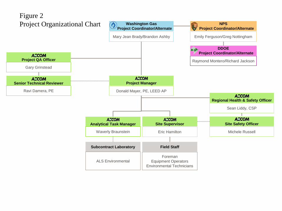
Project management, coordination, and communication will be vital to successful execution of this project. Project organization is described in detail in Section 8, and quality control and communication details are provided in the CQAP.
AECOM Washington Gas OU1 RD/RA Work Plan – East Station Site
September 2014
7-2
WG will schedule and lead project coordination and status update meetings, including the following:
• A project kickoff meeting was held in November 2012 with NPS, the District, and WG to ensure that all parties were in agreement regarding the scope and extent of the RA work.
• A preconstruction conference as required by the SOW with all appropriate parties, including AECOM personnel and specialty subcontractors, WG, NPS and its On-Site Representative, and the District will be held prior to commencing the field work. All project team members will be briefed on the scope of work and project schedule, tasks will be assigned to project personnel, and work will commence. The crew will be briefed on and required to comply with the HASP, and will be required to attend daily tailgate safety briefings.
• Weekly progress meetings will be held throughout the duration of the field work.
• Pre-final and final site walks will be held to identify punch-list items prior to demobilization, as described in Section 7.8.
WG will capture all relevant items discussed during these meetings to identify and communicate action items to the persons/parties responsible for their implementation. The project meetings will be used to effectively maintain communications, and provide a forum for the identification of project performance issues and the development of solutions to minimize delays.
7.3 Excavation Sequencing
The general excavation sequencing will be executed as follows. Note that actual conditions encountered during the execution of the project may dictate field changes to this sequence, including unknown conditions, weather, or real-time method adaptations to increase efficiency or project effectiveness. Excavation operations are described in greater detail in Section 7.5.
• Starting at the western end of the site, a 4 ft wide strip of surface soil adjacent to the full length of the seawall (with the exception of along the USACE-managed parcel, as shown in Drawing C-05) will be carefully removed using a small excavator or hand tools to a minimum depth of 1 ft and a maximum depth of 1.5 ft. If no MG waste is observed per the criteria listed in Section 6.1, the depth will be limited to 1 ft. As the excavation progresses along the seawall, a second crew will place clean fill along this strip, to within 6 inches of the final grade. Super Silt fence will be installed along the seawall within the clean fill, providing E&S protection during earthwork activities. Topsoil will be placed after the Super Silt fence has been installed. The Super Silt fence will be maintained until after the Performance Standards have been met, as described in Section 7.8. Silt fence removal procedures will be provided in the O&M Plan.
• Excavation will start on the western end of the Site and generally progress towards the east. The area along the western provisional boundary will be excavated first, and additional soil will be removed to the west of that provisional line if necessary (in accordance with Section 6.1). The area will be excavated to 1 ft depth, with additional excavation up to 3 ft as required by the CD. Excavation will proceed in this manner until reaching the USACE ramp off of Water Street SE.
• Excavation on the west side of the Site will typically be performed using 2 tracked excavators, with a rubber tire loader used to transport soil to the loadout point. The loadout area (see Drawing C-04) will be located in the gravel area to the north of the pump house, immediately to the east of the former easternmost DCDPW carport (WG intends to demolish the pump house prior to the excavation, if it receives all necessary approvals and permits from the District). Excavated soil will be placed in this area by the loader, on top of soil that will be excavated and
AECOM Washington Gas OU1 RD/RA Work Plan – East Station Site
September 2014
7-3
disposed of later in the sequence, and loaded into disposal dump trucks using a dedicated excavator. This area is adjacent to the primary truck access point (the eastern entrance and decontamination pad shown on drawing C-05) and provides adequate turn-around space for dump trucks, using the existing gravel drive at the east end of the site. Loading the soil from this point will prevent dump trucks from driving across the site, reducing dust and potential cross-contamination. It will also reduce the traffic traveling between the USACE ramp and the fenced USACE facility, which would become a pinch point with dump trucks traveling both directions combined with heavy equipment and USACE access.
• After excavation is complete from the west end to the USACE ramp, backfill operations will commence. Filling operations will start at the ramp, and work back towards the south and west. A separate crew and equipment will be used to spread and compact the clean fill. Trucks delivering clean fill will remain on areas that have not been excavated (existing stone/asphalt surface) or on clean fill once it has been placed. A gravel access road may be installed across excavated areas (approximately 6-inch gravel thickness). During backfill and restoration activities, the gravel will be removed and stockpiled on WG property for future use there (if it has not directly contacted any MG waste), or disposed of offsite as discussed in Section 7.6. Clean fill will be compacted as it is placed.
• A separate topsoil crew may be used to install the top 6 inches of material, working behind the clean fill crew.
• The second phase of excavation will start at the eastern provisional boundary and work towards the center of the Site. If required, additional soil will be removed to the east of the provisional boundary (in accordance with Section 6.1). Excavation will continue up to the USACE fence. A combination of temporary staging and live loading will be performed on the east end, depending upon excavation rates and disposal truck availability. Disposal trucks will remain on areas that have not been excavated or on clean fill.
• Similar to the west end, clean fill operations will move in the opposite direction of the excavation (towards the east), starting after the excavation has been completed and working on clean soil to the provisional boundary line. Topsoil placement will follow clean fill placement and compaction.
• Excavation work from the eastern and western ends will converge on the middle of the site, adjacent to the USACE property. Sequencing will be coordinated with USACE to ensure continual access to their facility. Once both sides of excavation have been completed, the remaining areas will be excavated and filled, working from the south to the north for excavation and then back toward the south for filling.
• The two parcels on the north side of Water Street SE will be excavated and filled towards the end of the project. Both small parcels will be excavated starting on the northern side and working towards Water Street SE, then filling operations will work from south to north using a separate crew and equipment. A decontamination pad will be constructed at the entrance to each of these areas, where all vehicles will be inspected and properly decontaminated in accordance with the procedures described in Section 7.4.8.
7.4 Mobilization and Site Preparation
Prior to mobilization, WG will coordinate with the adjacent property owners or managers (USACE, DDOT, and the boat clubs) and local authorities (the District) regarding emergency planning, E&S control, and traffic control. Access agreements and procedures are described in the SMP that is part of the POP for this project. WG will also provide a letter to NPS and the District documenting initiation of the field construction (RA).
AECOM Washington Gas OU1 RD/RA Work Plan – East Station Site
September 2014
7-4
7.4.1 Fencing
To prevent unauthorized foot and vehicle access to the Site during excavation and vegetation establishment, WG will install chain link security fencing around the perimeter of OU1. The existing fence on the west side of OU1 and along Water Street SE to the eastern entrance/driveway will be maintained, with repairs made as necessary to ensure integrity. New fencing will tie into the existing fence and continue along Water Street SE to the westernmost boat club, where it will turn 90 degrees and extend to the seawall. New fence may be necessary in portions of the western side of OU1, where the DCDPW building has been removed; fence replacement or repair in this area will depend upon discussions with DDOT and their ongoing use of the area between the former DCDPW building and the new 11th Street Bridge abutment. Approximate fence locations are shown on Drawing C-05.
Internal fencing that is not intended for future use will be removed and disposed of off-site. This will include fencing around the pump house and fencing parallel to the seawall south of the former DCDPW building. Fencing around the USACE facility will remain in place.
Two access gates will be provided off of Water Street SE, one maintaining USACE access through the existing gate (at the asphalt ramp, as shown on the drawings), with a second gate at the driveway on the eastern end of OU1 (“Eastern Entrance” on Drawing C-01). The fence will encompass the proposed excavation areas as well as a staging and laydown area. A 3-foot-tall Super Silt fence will be installed on the lowest elevation contour along the seawall to ensure that sediment will not flow from the Site into the Anacostia River. The fences will remain in place and be maintained by WG to protect seeded areas for at least 2 years after vegetation establishment.
7.4.2 E&S Control
The E&S Control Plan for the OU1 RA is provided in Drawings C-05 and C-06. Concurrent with starting earth disturbing activities at OU1, WG will install all required E&S control measures, including 3 ft tall Super Silt fence for erosion control along the seawall (as described in Section 7.3) and standard silt fencing at the eastern and western OU1 provisional boundaries (lowest Site elevation contour) to prevent the potential off-site surface migration of contaminants. Super Silt fence will not be installed along the USACE-managed parcel; standard silt fence will be installed on the east and north sides of the USACE area, with an earthen berm on the west side. The silt fence and Super Silt fence will be installed as described in Section 3.4 of the SMP. If excavation is required beyond the provisional boundaries, the silt fence will be relocated as needed to control stormwater runoff.
Excavation sequencing is intended to prevent dump trucks hauling waste or clean fill from traveling over potentially contaminated soil. If required, temporary haul roads will be constructed with geotextile fabric covered with clean gravel over any potentially MG-contaminated soil that will be traversed by hauling vehicles to avoid tracking waste between locations and to public roads. Gravel construction entrances will be installed at each gate from the edge of the pavement to the work area as needed to minimize dust generation from truck traffic. These measures, among others as necessary, will be employed to prevent soil tracking from the Site to Water Street SE or other public roads. Additional stone will be readily available on-site throughout the effort and will be used as needed to augment the haul corridors or at the entrances.
It is WG’s intention to directly load and place materials to the fullest extent possible, recognizing that some staging of soils will be necessary while site work is ongoing. A temporary soil staging area will be constructed at the loadout area (see Drawing C-04) in the gravel area to the north of the pump house, immediately to the east of the former easternmost DCDPW carport. This area will be excavated after
AECOM Washington Gas OU1 RD/RA Work Plan – East Station Site
September 2014
7-5
the staged material has been removed, and is intended to stage soils for no longer than 2 to 3 days (maximum of 1 week) prior to off-site disposal.
Clean soil (no visual, olfactory, tactile, or PID indication of MG waste) will be used to create small berms around the perimeter of the proposed soil staging area (within the loadout area) to prevent run-on/runoff, and the pile will be covered with 6 mil poly sheeting that will be secured at the end of each day and during daytime rain events. The poly will be secured using soil, sandbags, concrete blocks, and/or stones, and inspected at least daily during the project to ensure integrity. Silt fence will be installed around the perimeter of the stockpile, to be properly staked and secured at the end of each workday and prior to any rain events.
7.4.3 Trash Removal and Tree Clearing
The District has committed to removing the bulk debris and solid waste that has been dumped along the gravel access driveway and in the wooded area adjacent to the eastern provisional boundary, along with any other trash and debris throughout the Site immediately prior to AECOM’s mobilization to begin RA activities. WG will coordinate the timing of the District removal of illegally dumped trash with the installation of the security fence to ensure all trash is removed by the District prior to installing the fence. After the fence has been installed, WG will be responsible for collecting and disposing of wastes generated by contractors and subcontractors working at the Site. Any additional trash or debris that is illegally dumped on OU1 will be cleaned up by WG’s contractor and placed in rolloff boxes for off-site disposal by the District.
Fencing and other features in the excavation area will be removed and recycled or disposed of. The area to the east of OU1 will be cleared to the hardwood canopy tree line (i.e., the provisional eastern boundary) to expose the areas where excavation is anticipated; other trees and vegetation will be removed throughout OU1 where excavation is planned.
The majority of the trees and heavy brush were cut down on April 15 and 16, 2013, prior to final NPS approval of the Work Plans and prior to mobilization for the excavation work. WG obtained NPS approval for this activity in a separate communication with sufficient detail to facilitate NPS’s review.
Trees and brush were cut above the ground, and roots/root balls remain in the ground to be removed during the excavation work. Vegetative debris was cut up and staged in several consolidated areas on site for future disposal. USACE accepted a limited amount of trees and tree limbs, which they disposed of with wood debris that they had removed from the river.
After mobilization for the RA, the remaining vegetative debris will be placed in rolloff boxes or dump trailers for off-site disposal. Root balls and roots will be removed as excavation proceeds and disposed of with the excavated soil. Care will be taken to remove any root systems adjacent to the seawall, in order to avoid damaging the concrete structure with heavy equipment. If roots are intertwined in the seawall, they will be cut to free the remaining root system.
If the lateral excavation limits are required to be extended based on the presence of impacted soils, additional clearing and grubbing may be required to the east of OU1. Trees located within the hardwood canopy east of the eastern provisional boundary are likely to be damaged if their roots are within the planned excavation area. When excavation is occurring within 10 feet of the eastern provisional boundary, increased inspections will be required so that precise locations of MG wastes in soil between 1 and 3 ft will be marked. If a large tree is within the 10 ft radius of the closest MG wastes, it will be removed and excavation will progress concentrically until the 10 ft radius is free of MG wastes.
AECOM Washington Gas OU1 RD/RA Work Plan – East Station Site
September 2014
7-6
7.4.4 Utility Clearances
Proper utility clearances will be obtained prior to any ground disturbing activities, as described in Section 7.1.2. All utilities identified during the design phase will be re-marked, and a valid Miss Utility ticket will be maintained. Stakes marking utility locations and depths will be maintained or replaced (based on recorded location and depth information) as necessary to ensure that all stakes remain visible and can be verified prior to and during operations.
Before initiating excavation, WG will identify buried utilities (both active and presumed inactive) to a depth of 5 ft in the field using grade stakes at 25 ft intervals and flagging (or similar). At each grade stake location, the burial depth (relative to original grade) of each utility will be determined or confirmed using hand tools, surveyed with the GPS, recorded in a bound field notebook, and written on the corresponding grade stake using indelible marker.
A 16-inch diameter gas transmission line runs through OU1 from the former WG facility to the river. The exact depth of this line is unknown, so air knife or hand tool methods will be employed to identify its exact location and depth. WG requirements typically prohibit mechanized equipment within 18 inches of gas lines. Additional utility clearance information is described in Section 7.2.1 and in the SMP.
7.4.5 Protection of Monitoring Wells and Seawall
Proper protection of site features that are designated to remain during and after construction will be an important part of the safe and successful execution of this project. Protection of monitoring wells and utility lines during excavation and restoration activities will be achieved by communication, marking, and physical protection where practical. Prior to excavation, all known utility and treatment system line locations will be clearly marked, and a combination of orange safety cones, orange safety fence, and water-filled orange plastic Jersey barriers will be used to mark well locations and other existing features that will remain in place during the project. All heavy equipment operators and technicians will be briefed on the locations of these features, and daily safety meetings will stress awareness and protection. Careful excavation, guided by AECOM field staff on the ground, will be employed within 5 ft of existing wells and similar features to be preserved. Excavation will be limited to hand tools within 2 ft of the Site feature. At monitoring well locations where the protective casing or flush-mounted cover is encased in concrete, near-surface soil beneath the concrete may remain in place around the wells in order to ensure their continued integrity. Any remaining soil that is determined to be MG impacted will be mapped using a GPS and included in the project closeout report as described in Section 7.10. While every measure possible will be taken to ensure the protection of all monitoring wells, there is still the potential for inadvertent damage as a result of on-site construction activities. Wells may be driven over by heavy equipment, struck by excavator buckets, and/or buried by soil relocation. Although any well identified to be broken will be handled on a case-by-case basis, the plan for repair or relocation will be very similar. If one or more of the monitoring wells becomes covered over by relocated soil or construction debris, the first step will be an attempt to manually unearth the well. The next step would be to utilize a metal detector to locate the metal flush-mount or stickup casing. Finally, all of the on-site wells have previously been surveyed and the well location will be confirmed through GPS coordinates.
If the integrity of the flush-mount or well stickup is compromised and foreign materials enter the well, well redevelopment activities will be required before the well is sampled as part of the OU2 investigation or annual monitoring. In the case that the riser (well casing above-grade) is bent or broken, WG will cut the riser below the damaged area, connect a coupler, and extend the riser back above-grade. If extending the well or replacing a section of damaged PVC near the surface, a minimum of three stainless steel screws will be used to attach each of the PVC casing sections to the coupler. Screws used to join to the
AECOM Washington Gas OU1 RD/RA Work Plan – East Station Site
September 2014
7-7
coupler will be short enough to prevent the screws from entering into the interior of the well casing. No solvent cements will be used in the repair. Once the well riser has been restored and/or well development is complete, a new flush-mount or stickup will be installed to protect the security of the well. Finally, well riser and flush-mount/stickup elevations will be surveyed to ensure accurate future groundwater elevations. If the well is extensively damaged and cannot be adequately repaired, it will be properly abandoned and replaced (if necessary) as part of the OU2 investigation.
Care will be taken to protect the historical seawall, including the excavation setback measures described in Section 6.2. The seawall is continuous along the southern boundary of the Site, with the exception of approximately 70 ft of shoreline adjacent to the western provisional boundary (in the area of the former 11th Street bridge abutment). This area of the shoreline is south of the stormwater retention pond installed by DDOT during 11th Street bridge construction activities, and is currently protected by Super Silt fence. The Super Silt fence was installed as close to the eroding shoreline as possible, and will be used during OU1 excavation to demarcate the southern extent of the excavation and continue to provide protection to the river. Consistent with E&S control measures described in Section 4.2, the Super Silt fence will be inspected prior to and during excavation work, and will be repaired and maintained as necessary. If DDOT removes the Super Silt fence before or during the OU1 RA, WG will replace it before performing any RA excavation, soil placement, or regrading activities within 100 ft upgradient of the fence.
The only other area on the Site where the seawall is not continuous is an approximately 3 ft long gap in the vicinity of the USACE-managed property. This area will be protected in a similar manner as described above, with the installation of Super Silt fence along this gap to prevent damage to the seawall and prevent silt or soil from entering the river. As described in Section 6.2, the 4 ft wide strip of surface soil immediately adjacent to the seawall will be carefully removed using a small excavator or hand tools.
7.4.6 Demolition of Structures
All demolition of existing structures will be performed outside of the RA. Prior to starting the excavation portion of the RA, 4 existing structures in the OU1 area outside the USACE property will be demolished. The District has demolished the DCDPW structures, which include a one-story metal building on the west end of OU1 and two storage shelters (carports) adjacent to Water Street SE. The concrete floor slab and footers for the single-story structure will be demolished and properly disposed of by WG prior to starting the RA excavation. If demolition activities require some temporary soil excavation to depths greater than 3’, the soil will be managed as required by the CD.
WG intends to demolish the abandoned WG pump house under a separate project prior to beginning the OU1 excavation, if it receives the appropriate approvals and permits from the District. The hole created by the pump house basement will be filled with imported coarse aggregate and/or soil, and the surface (i.e., within 3 ft of final grade) will be completed with clean fill and topsoil as required by the CD.
7.4.7 Health and Safety Control Measures
Health and safety control measures are described extensively in the site-specific HASP. Some of the major H&S activities will include the following tasks: establishing control areas; setting up vapor and dust monitoring stations upwind and downwind of the work zones; implementing the daily reporting of air monitoring results; and implementing daily safety tailgate safety meetings.
WG will establish and manage a support zone (SZ), exclusion zone (EZ), and contamination reduction zone (CRZ) as required by 29 CFR 1910.120. When potential exposure has been effectively controlled in accordance with 29 CFR 1926.62, work areas will be established and managed so that only
AECOM Washington Gas OU1 RD/RA Work Plan – East Station Site
September 2014
7-8
authorized personnel enter the work area, proper PPE is in use, equipment/tools are properly cleaned before leaving a work area, and all work areas are effectively identified and marked.
When working under HAZWOPER requirements, WG will set up a SZ at OU1 consisting of an office trailer and necessary storage to serve as its base of operations for all of the site activities. The SZ will be the meeting place for all personnel and subcontractors at the beginning of each shift where the Site Supervisor (defined in Section 8.1.3) will conduct the daily safety meeting and distribute work assignments for the shift. There will be designated space within the trailer for oversight personnel, and the two spaces will be separated by a locking door. WG will supply each side of the trailer with a power source adequate for running two computers, in addition to a wireless internet connection that will be functional and accessible for a minimum of two devices on each side of the trailer during all working hours.
Prior to the start of any excavation activities, AECOM will establish and control an EZ around the work area. The EZ will be identified using construction fence or caution tape and access will be restricted to authorized personnel. One point of entry/exit will be established at the EZ.
A CRZ will be established just outside the entry/exit point of the EZ. All authorized personnel entering/ exiting will be required to pass through the CRZ, which will be equipped with receptacles for trash and PPE, and with washing stations. When entering the EZ through the CRZ, workers will don any necessary PPE. When exiting the EZ, workers will place any equipment, tools, or supplies in the drop area as they enter the CRZ, take off any PPE and place it in the proper receptacle, and wash their hands and face prior to exiting the CRZ. If any hand tools, equipment, or supplies are removed from the EZ, they will be cleaned/decontaminated in the CRZ. For equipment or tools that are too large to pass through the CRZ, WG will establish and control a temporary decontamination area just outside of the EZ where large equipment and tools will be decontaminated and any washwaters and material generated during decon activities will be collected and stored for proper disposal.
7.4.8 Vehicle/Equipment Decontamination Pad
AECOM will construct a decontamination pad near the center of OU1 just outside of the EZ where large equipment and tools and vehicles will be decontaminated. The decontamination pad will be underlain by a 30-mil high-density polyethylene (HDPE) liner and a 10-ounce nonwoven geotextile fabric, constructed so that any decontamination liquids collect in a sump for off-site disposal. All liquids and solid wastes generated during the decontamination process will be collected and containerized, appropriately labeled, and disposed of off-site. Wash water disposal will typically entail solids filtration (using a bag or cartridge filter) and pumping through the East Station groundwater treatment system operated and maintained by WG. No decontamination liquids will be released to the ground or to surface waters. A gravel road will be maintained between the decontamination pad and Water Street SE (to include the construction entrance), in order to prevent tracking of dirt off-site. If the HDPE liner is punctured the decontamination pad will be deemed unusable until the liner is replaced.
With the exception of vehicles that access the USACE building and do not contact contaminated or loose soil, every vehicle that enters the Site during the RA must leave via the decontamination pad for inspection and will be decontaminated as needed, so that soil is removed from the vehicle and tires. This requirement applies to excavating and backfill equipment and trucks, in addition to third-party contractors such as those who enter the site to perform utility work, refuel vehicles, service portable toilets, or make deliveries. If egress cannot be controlled by on-site staff, barricades will be erected to guide all vehicles through the decontamination pad.
AECOM Washington Gas OU1 RD/RA Work Plan – East Station Site
September 2014
7-9
7.4.9 Dust and Dirt Control
In order to suppress dust and prevent its release from the Site, the crew will apply water as necessary to unpaved areas wherever pedestrian or vehicular traffic may be affected by dust generated during construction activities, including demolition, excavation, grading, and backfilling activities. A water truck will be used to suppress dust during dry, windy conditions and as needed.
Fugitive dust created as a result of demolition and excavation will be mitigated in accordance with the HASP; WG will spray excavation areas and construction roadways as needed for dust control with water from an approved source. Trucks leaving the Site will have their tires washed on the decontamination pad as needed to prevent tracking of materials off-site. If there is visible evidence of Site material tracking via truck tires onto public roads, no trucks will exit the Site until the road has been cleaned and the truck tire cleaning procedures have been modified to prevent off-site tracking. All vehicles and heavy equipment will be inspected prior to leaving the Site to ensure they are clean. For waste soil transport vehicles, truck inspection logs will be maintained by WG to ensure the following criteria are met: 1) vehicle arrives on-site clean and free of leaks; 2) the truck bed is equipped with a plastic bed liner; 3) the tailgate latch(es) are secured; 4) the trailer license plate number is recorded; 5) the truck number and hauler identification is recorded; 6) the signed manifest has been exchanged; 7) the departure time is recorded; 8) the truck tires leave the Site clean and no off-site tracking occurs; 9) and the load is covered prior to leaving the Site. All waste haulers must be pre-approved by NPS before working at the Site.
WG will perform continuous air monitoring for vapors and particulates to be protective of both workers and the public in the vicinity of OU1. Monitoring will be performed in accordance with the AMP. Alert and action levels have been determined for the specific constituents anticipated to be present during excavation. Alert levels are total VOCs 1 ppm above background for a 15-minute average, particulates at 100 µg/m3, and action levels are total VOCs 5 ppm above background for a 15-minute average, particulates at 150 µg/m3.
Vapor concentrations above the alert level for a 15-minute average will result in temporary stoppage of work and evaluation of the condition; instantaneous readings above the action level will result in immediate shutdown of operations. If vapor levels cannot be maintained below the alert level, preventive actions will be taken including upgrading PPE for Site workers (assuming perimeter concentrations are below alert levels), use of engineering controls to reduce potential exposure, or potentially erecting a protective structure around the highly impacted area to contain vapors during excavation.
Particulate readings above the alert level for a 15-minute average will also result in temporary work stoppage, and readings above the action level will result in immediate work stoppage. If levels cannot be maintained below the alert level, dust suppression methods such as water sprays will be employed to reduce emissions to an acceptable level.
Odor control will be more subjective; if unacceptable odors are apparent during routine perimeter monitoring, odor suppression measures such as odor-masking agents or odor-suppressing foam will be employed, after written approval for the use of specific odor suppression agents has been provided by NPS. WG will maintain contingency foaming equipment and materials for TVOC and odor suppression, either on-site or immediately available from a supplier.
AECOM Washington Gas OU1 RD/RA Work Plan – East Station Site
September 2014
7-10
7.5 Excavation
WG’s excavation plan is based on efficiency, productivity, and schedule. Sequencing the excavation, backfill, and revegetation work to minimize the area of contaminated soils exposed to the atmosphere will help control odor, vapor, and dust emissions. The planned approach and schedule has been developed to minimize impacts on the USACE, adjacent property owners, and the public caused by dust, construction traffic, and traffic restrictions/diversion during remediation activities. The excavation sequence is discussed in Section 7.3.
Standard construction techniques will be used to control sediment and stormwater run-on and runoff during excavation, and will include Super Silt fence at the seawall, silt fences, earthen berms, hay bales, and gravel construction entrances as described in Section 7.4.2. Backfilling and re-vegetation will be performed as soon as practicable to prevent erosion and stormwater runoff. Erosion control structures will be installed before excavating, if possible, or immediately after excavation and no later than the end of each day to prevent sediment-laden runoff from the excavation.
Standing water that does not drain from low areas will be dewatered before excavation or backfilling. Water removed from the Site will be pumped through the WG East Station wastewater treatment facility.
Excavation will be performed using tracked hydraulic excavators (trackhoes), generally progressing from west to east across OU1, and then east to west, as described in Section 7.3. Direct loading to dump trucks or dump trailers will be maximized as practical to limit double handling. For excavation on the east side of the site, a consolidated loadout area will be established as shown on Drawing C-05 and discussed in Section 7.3. Disposal vehicles will remain on gravel haul roads, clean fill after placement, or existing gravel areas to limit contact between truck tires and potentially contaminated soil. Stone access roads will be created as needed to facilitate clean pathways for the disposal vehicles. The need for these stone access roads will be dictated by whether the public roads can be maintained completely clear of tracked Site material. As stated in Section 7.4.8, any Site-related vehicle will be inspected and decontaminated (as needed) before leaving the Site to prevent soil tracking to the road.
Where direct loading is not practical due to site constraints or when performing excavation to 1 ft depths over large areas, the excavators will pile the removed soil behind the machine in windrows. This approach will minimize cross contamination to clean surfaces, as opposed to blading surface soils with a bulldozer. A rubber tire loader will be used to consolidate the removed soil into the loadout staging area on the eastern side of the property, as shown on Drawing C-05. An excavator or the loader will also be used to place the soil in disposal transport dump trucks as they arrive on-site. Using rubber tire loaders versus tracked loaders will result in less dust and more efficient operation.
WG anticipates loading between 45 and 50 trucks per day for off-site disposal (20 to 22 tons per truck), based on availability of transport vehicles and assuming disposal at the New Castle, Delaware facility described below. Potential issues related to truck traffic on Water Street and other truck routes are discussed in the SMP.
The excavation depths will be monitored and confirmed using a laser level and rod. Grade stakes will be installed on a 50 ft grid throughout the site to delineate proposed cut depths (1 ft or 3 ft as discussed in Section 3.1). The level will be used to verify appropriate cut depths, and these depths will be recorded for the as-built drawings. Similarly, grade stakes will be placed on 50 ft grids to established required fill heights, and the level will be used to spot check and verify appropriate fill depths.
WG will remove soil using a tracked excavator to the boundaries described in Section 6.1. In areas where MG wastes are observed by visual, tactile, or olfactory means or detected with a PID at a 1 ft
AECOM Washington Gas OU1 RD/RA Work Plan – East Station Site
September 2014
7-11
depth, the excavation area will be expanded in 10 ft increments radially or downwards until one of the following occurs:
• Groundwater is encountered;
• A maximum depth of 3 ft is reached (or a maximum depth of 1.5 ft is reached and the excavation is within 2.5 ft of a structure); or
• A 10 ft horizontal radius of non-impacted soil is established beyond the observation of MG waste.
GPS measurements will be taken to identify the boundaries of excavated soil, and depths of soil removed will be carefully recorded for development of as-built drawings. This information, as well as location and depth-specific descriptions of soil, PID readings, olfactory observations, and locations of observed MG wastes at the maximum required excavation depth, will be recorded with GPS and included on the as-built drawings. Information regarding the GPS locations, depths, and specific descriptions of the type of waste left in place will be included with the maps. This information will be provided with the project closeout report.
An indicator fabric layer will be placed at the bottom of the excavation where residual contamination is evident in the remaining soil.
7.6 Impacted Soil Management
All project waste operations will be conducted in accordance with applicable regulations and requirements, including state and federal regulations such as RCRA, Toxic Substances Control Act (TSCA), and Department of Transportation (DOT), as well District-specific requirements outlined in Section 4.7. The selected off-site disposal facility will provide USEPA verification that it operates in compliance with Section 121(d)(3) of CERCLA, 42 U.S. Code (USC) 9621(d)(3), and 40 CFR 300.440, as required by the CD. Prior to shipping the MG waste outside of the District, a notification letter will be sent to the receiving state’s environmental official (anticipated to be Delaware Department of Natural Resources, Division of Waste and Hazardous Substances) as well as the NPS Project Coordinator and the District representative. The written notice will include the name and location of the receiving facility, the type and quantity of waste material to be shipped, the schedule for the shipment, and the method of transportation. Approval from the state environmental official, the NPS Project Coordinator, and the District representative will occur before implementation of any major changes in the shipment plan, such as a decision to ship the Waste Material to a different out-of-District facility. The RA will not commence before NPS approves the disposal facility and hauler(s).
WG will notify NPS of off-site waste shipments at least 15 days in advance. WG will generate a list of waste haulers to be approved by NPS and reviewed by the District representative. WG will provide to NPS for approval the proposed hauler(s) insurance information and licensing, as well as documentation confirming the hauler does not have any outstanding violations.
The soil is planned to be disposed of at a thermal treatment facility, anticipated to be Clean Earth of New Castle, Delaware (CENC). This facility is the most proximate MG waste thermal desorption facility to the Site, and they have provided competitive pricing for transportation and disposal. WG is actively investigating alternative disposal facilities and will submit information regarding all proposed disposal facilities to NPS for approval prior to initiating the RA field work. Final disposal facility selection will be based on waste acceptance, capacity, pricing, and approval of the facility and hauler(s) by NPS in accordance with the terms of the CD.
AECOM Washington Gas OU1 RD/RA Work Plan – East Station Site
September 2014
7-12
The OU1 shallow contaminated soil will be pre-characterized for disposal prior to starting excavation. WG will collect approximately 24 composite waste characterization samples (1 per 1,000 tons) from various depths between 0 and 3 feet below ground surface throughout OU1, and will obtain pre-approval from the waste disposal facility. This includes 2 samples beyond each of the provisional boundaries, in case additional waste is generated in those areas in accordance with Section 3.1. Sampling rationale and procedures are described in Section 3.1 of the FSP.
A letter from the approved waste-receiving facility will be forwarded to NPS documenting that they approve of the number and type of samples to be collected for pre-characterization, and a follow-up letter will be provided when they have received all required data and agree to accept the waste. CENC-required analyses include reactive cyanide and sulfide; ignitability; corrosivity (pH); total organic halogen (TOX); petroleum analyses including BTEX (benzene, toluene, ethylbenzene, and xylenes), total petroleum hydrocarbons (TPH) for both gasoline range and diesel range organics (GRO/DRO), and PAHs; polychlorinated biphenyls (PCBs); metals (suite of 16); and toxicity characteristic leaching procedure (TCLP) with analysis of metals, VOCs, semi-volatile organic compounds (SVOCs), pesticides, and herbicides. Sampling and analysis for waste characterization is described in detail in the SAP.
Prior to shipping waste, WG will complete all facility-required waste profiles. Signed waste profiles will be submitted to the designated and approved facility for waste acceptance/approval, with copies sent to the NPS Project Coordinator and the District representative.
Trucks will be direct loaded using an excavator or loaded from the consolidated loadout area using a rubber tire loader or excavator. To minimize spills and overloading of trucks, loading will be supervised by an individual dedicated to this task who will also be responsible for maintaining the truck inspection log described in Section 7.4.9. A bill of lading/manifest will be prepared for each shipment of impacted soil and will be signed by WG. All trucks for transporting bulk solid wastes will be lined and covered with solid tarps prior to leaving the Site, and trucks will be inspected to ensure that no solids or liquids are able to spill out. All trucks will be required to display appropriate DOT placards and required permits will be checked prior to loading. Vehicles will be inspected for integrity and proper placarding prior to loading, and to ensure appropriate load heights, containment, and clean tires prior to leaving the site. All transport vehicles will be properly decontaminated before leaving the Site to ensure no soil is deposited onto public roads during transport to the disposal facility.
Each transportation vehicle and driver will have all appropriate state and federal permits and WG will be responsible for preparing complete and accurate shipping documents. The shipping documents will also be signed by the driver prior to the waste leaving the Site; these documents will accompany all shipments of waste while in transit at all times.
Transport vehicles containing bulk solid waste (RCRA non-hazardous soils) will be weighed at the receiving disposal facility to track the quantity of soil removed from OU1. The certified disposal facility weight tickets will be collected and tracked. WG will actively maintain and track data and information related to OU1 wastes, including all disposal analyses by waste type, manifests/bills of lading, and disposal facility weight tickets.
7.7 Backfill
Clean fill (in accordance with CD criteria) will be imported and installed to 0.5 ft below final grade, compacted as described below, and topsoil will be installed on the top 0.5 ft to match the proposed grade in accordance with the grading plan (Drawing C-07) and the accompanying grading tables (Drawing C-08). The proposed fill source will be sampled in accordance with the construction specification and analyzed for VOCs, SVOCs, pesticides, PCBs, metals, cyanide (if necessary),
AECOM Washington Gas OU1 RD/RA Work Plan – East Station Site
September 2014
7-13
dioxins/furans, pH, and organic matter. Sampling and analysis will be performed in accordance with the OU1 SAP, and clean fill will be verified in accordance with Section 6.4 of this Work Plan.
Successful fill compaction is critical in order to minimize erosion of the fill, create stable slopes, and control sediment migration. The provisions and procedures in this section will be followed wherever compacted fill is to be placed on-site. Standing water and soft soil will be removed via pump from excavated areas or allowed to infiltrate prior to filling. Collected water will be filtered and discharged to the WG groundwater treatment system. Any soft soil or sediment will be spread in an upland area and allowed to dry before being incorporated into the compaction process. Moist soils may be mechanically aerated or mixed with dry soils to achieve optimum moisture for compaction when such soils are to be used as compacted fill. Compaction and quality control testing will be performed in accordance with the following provisions:
• Whenever possible, compaction of approximately 8-inch uncompacted horizontal lifts will be performed using a sheepsfoot compactor before placing a subsequent lift.
• Hand operated and/or mechanical tampers may be used to compact 4-inch uncompacted lifts in areas that are not accessible by the sheepsfoot roller.
• All compacted soil, except the final 6 inches of topsoil, will meet or exceed 85 percent of Standard Maximum Dry Density (SMDD). The topsoil (top 6 inches) will be compacted to 80% SMDD, as recommended by USACE to balance mechanical stability with plant growth capacity.
• Moisture content shall be maintained during the compaction process to the extent necessary to allow achievement of compaction criteria and control fugitive dust.
• One nuclear moisture/density test (ASTM Method D6938-10) shall be completed for every 100 tons of soil. It is assumed that 100 tons of soil is equal to approximately 75 cubic yards of compacted soil. The required testing frequency is, therefore, once per every approximately 3,000 square feet of compacted soil for 8 inch lifts. Accordingly, for 0.5 ft compacted lifts, one test will be performed for every approximately 4,000 square feet of lift area.
• Care will be taken to measure moisture and density shortly after fill is compacted to ensure the near-surface moisture content represented by the nuclear density gauge measurement is representative of the moisture throughout the entire compacted lift.
• No compaction with large construction equipment (e.g., sheepsfoot compactors) will occur within 5 ft of existing monitoring wells. Such compaction will be performed using hand-operated equipment as described above.
• In accordance with WG procedures, hand-operated compaction equipment will be used within 24 inches of the 16-inch buried gas transmission line.
• Density measurements will not be collected in areas where oversized material (rocks or stone) is obviously present so that the measured densities reflect the compaction of material that would likely pass a #4 sieve.
• Before compaction, the nuclear density gauge moisture measurement, determined by test method ASTM D 6938-10, will be verified according to the procedure in the FSP.
• Moisture/density test locations and associated results will be provided to the NPS On-Site Representative by 10 AM on the next business day after the tests are performed.
The grade will be contoured to promote and facilitate sheet flow surface water drainage throughout OU1, as shown on Drawing C-07.
AECOM Washington Gas OU1 RD/RA Work Plan – East Station Site
September 2014
7-14
7.8 Site Revegetation and Restoration
The finished product of this RA will be consistent with the requirements of the SOW, including returning the OU1 area to existing grade. The final grading design will also promote stormwater sheet flow run-off while protecting the Site soils from erosion. The proposed grading plan is provided as Drawing C-07. Grade stakes placed on 50 ft grids throughout the Site before excavation will be used to confirm depth of cut and depth of fill. Field survey instruments will be used to take spot elevations to verify that re-established grades are similar to the pre-excavation grade. After final grading, the Site will be resurveyed by a licensed surveyor to confirm the contours of the Site match the grading plan (Drawing C-07) and the accompanying grading tables (Drawing C-08).
The unpaved excavation areas will be revegetated in accordance with the Performance Standards as described in Section 3. The Site soil will be seeded with a grass and herbaceous plant seed mixture consisting of at least eight native/naturalized species. The seed mix will include a temporary rye or similar species as a fast soil cover and will include hardy native or naturalized species. The seed mix species, percent purity, germination, and percentage of the mix will be provided to NPS for approval prior to application. Seeded areas will be watered the day of completion of seeding.
After the OU2 RI/FS work is completed, additional shrubs and tree saplings to replicate, as much as possible, the physical characteristics of a typical riparian border of the Anacostia River, will be required upon consultation with the District. If stone is the only practical material that will meet the clean fill analytical requirements, alternative landscaping may not be possible in 6 inches of topsoil underlain by stone. WG will not be required to remove and replace any clean fill materials placed during the OU1 RA in order to support vegetation other than the grass as required by the Performance Standards in the SOW.
Gravel will be installed in areas that require a surface for vehicular traffic; the gravel areas are expected to be limited to an access road connecting the paved USACE entrance ramp to the USACE property gate and their pier. If the bike path areas have been defined prior to execution of this work, those areas will be finished with gravel as specified in the CD. Monitoring and maintenance of pavement or gravel surfaces to ensure a competent cover over clean fill will be performed for 2 consecutive years.
At the request of USACE, new fencing will be installed around the dock and loadout area, tied in to existing fencing. A 40 ft by 37 ft by 10 inch thick reinforced concrete pad will be installed adjacent to the dock for staging rolloff boxes, and the area within the new fence will be paved with asphalt.
The 0.2-acre triangular-shaped area at the northeastern intersection of 12th and Water Streets SE (part of Reservation 343D) may be used in the future as part of a natural gas filling station. Depending upon the timing of an agreement between WG and the District, the surface of this parcel may be stone or material other than topsoil to facilitate future development, following NPS concurrence.
The site drainage is currently poor, with a number of puddles and low spots observed during and immediately after rainfall events. To correct this issue, limited quantities of extra soil will be imported and graded throughout all of OU1 to establish good drainage patterns to promote sheet flow and limit concentrated flow towards the Anacostia River.
After substantial completion of the field RA activities, WG will perform a pre-final inspection with NPS and the District and prepare a punch list of any outstanding items requiring correction prior to acceptance of the work. After all of the punch list items have been appropriately addressed, a final inspection will be performed by NPS, the District, and WG.
AECOM Washington Gas OU1 RD/RA Work Plan – East Station Site
September 2014
7-15
The perimeter fence will remain in place for 2 years following completion of the RA or until a competent vegetative or pavement/gravel cover has been maintained over clean fill for 2 consecutive years, whichever is longer, as required by the CD and discussed in Section 7.9. Silt fencing and other E&S controls will be removed after grass is established and the Performance Standards have been achieved.
During execution of the OU2 RI/FS or subsequent work following the completion of the OU1 RA, care will be taken to protect the areas that were restored as part of the OU1 work. Any impacts to the clean fill/ topsoil, new grade, or vegetation will be repaired as necessary, including reseeding or other appropriate measures needed to continue to meet the Performance Standards as described in Section 3.
7.9 Institutional Controls and Remedy O&M
WG will develop an Institutional Controls Implementation and Assurance Plan (ICIAP) that identifies appropriate ICs for OU1, and provides procedures for implementing, maintaining, monitoring, and reporting on the ICs. The ICIAP will include all ICs necessary to ensure that the remedy implemented under the CD remains protective of human health and the environment and remains compliant with Site ARARs. The ICIAP will also provide for the establishment of ICs under the District’s Uniform Environmental Covenants Act (UECA), D.C. Official Code § 8-671.01, et seq. (2009).
The ICIAP will be submitted for review and approval by NPS; upon approval, WG will record the ICs with the District Recorder of Deeds. ICs will be monitored and enforced by means of an agreement with the District (Appendix E of the CD).
The OU1 ICIAP will include ICs that address the following restrictions:
• Limitations, conditions, or prohibitions on post-remediation excavations in the location of the OU1 soil remedy; and
• Reporting requirements for any previously unmapped tar at the District Property discovered after the completion of the Work at OU1.
An O&M Plan will also be developed in conjunction with the ICIAP. O&M will typically consist of the following measures that WG will perform between the final inspection of the RA completion and achievement of the Performance Standards:
• Inspection of the vegetative growth and E&S controls on a monthly basis to ensure that the measures remain protective and are functioning as designed;
• Repairs to silt fence, Super Silt fence, and other E&S measures as needed;
• Cleaning of accumulated silt/sediment from silt fencing;
• Accumulated sediment will be used to fill erosion channels, ruts, and rills as needed to prevent continued erosion and protect the River;
• Reseeding as needed to provide adequate vegetative cover; and
• Any other maintenance activities required to meet the Performance Standards.
7.10 Project Closeout Report
WG will prepare a project closeout report upon completion of OU1 remediation to document the successful completion of all items described in this and the accompanying project Work Plans, the CD,
AECOM Washington Gas OU1 RD/RA Work Plan – East Station Site
September 2014
7-16
and the CD SOW. The report will document that the Performance Standards were met, along with providing project procedures, any deviations from the design, and the results of the QA/QC inspections and testing. This report will include the following elements, at a minimum:
• A summary of field activities and photographic journal
• Actual quantities of work performed and waste stream information summary
• Deviations from the Work Plan
• QA/QC Data and inspection reports
• Copies of analytical results and field screening data
• Bills of lading/manifests and disposal certificates
• As-built maps and/or GIS map showing the following:
o Excavation boundaries/extents;
o Areas that did not require surface soil excavation;
o Areas that received 1 ft or 1.5 ft of excavation because they were located adjacent to a structure;
o Areas with MG waste at the bottom of the excavation that was left in-place and details regarding the type of waste present; and
o A corresponding GIS locations table with datum specified.
This report will be prepared in Draft form and will be submitted to NPS and the District within 60 days of the final inspection described in Section 7.7. This draft report will be finalized by incorporating NPS’s and the District’s review comments. The end result will be documentation that the performance standards have been attained. There will be a 5-year review process following excavation and revegetation.
AECOM Washington Gas OU1 RD/RA Work Plan – East Station Site
September 2014
8-1
8.0 Project Organization
The RD/RA activities will be performed and managed by AECOM on behalf of WG. AECOM has assembled an integrated team of experienced engineers, scientists, construction resources, and specialty subcontractors to perform the remedial design and remedial action for this project. Our project team has extensive environmental design and remediation experience, having successfully completed similar projects at other locations. An organization chart for the AECOM team that will execute this project is presented in Figure 2. These key project team members will be supported by regional technical and administrative staff as needed.
AECOM will perform the entire scope of work for this project, with the exception of specialty trades such as surveying, utility locating, compaction testing, hydroseeding, transportation, soil treatment, and disposal.
The project will be overseen by NPS in compliance with the CD requirements, CERCLA, and the National Contingency Plan. The WG Project Coordinator will be the primary contact for communications with NPS, and the AECOM Project Manager will support the WG Project Coordinator as needed. The AECOM Project Manager may communicate directly with NPS on technical matters related to the project. To ensure transparency and efficient project coordination, WG and AECOM will discuss all regulatory matters with NPS, who will disseminate information to the District as appropriate. The NPS Project Coordinator will be copied on all communications between AECOM or WG and the District.
8.1 Responsibilities
The following subsections briefly describe the responsibilities of the personnel assigned to this project. All on-site personnel are responsible for complying with the requirements of the project-specific Work Plan and HASP. The AECOM PM and Site Supervisor are to be responsible for implementing the plans and ensuring that all work requirements are enforced.
8.1.1 WG Project Coordinator
Ms. Mary Jean Brady will serve as the WG Project Coordinator. Ms. Brady’s responsibilities include:
• Representing WG management.
• Reviewing AECOM’s work.
• Serving as the primary contact for NPS and the District.
• Securing project funding.
• Reviewing all project documents before submission to NPS.
• Stopping work if an imminently dangerous situation exists. The emergency situation will be immediately reviewed with AECOM’s Site Supervisor, site personnel, and Project Manager.
AECOM Washington Gas OU1 RD/RA Work Plan – East Station Site
September 2014
8-2
8.1.2 AECOM Project Manager (PM)
The AECOM PM, Donald Mayer, PE, LEED AP, will be responsible for overall direction, implementation, and enforcement of project requirements, along with day-to-day management of technical and scheduling matters related to the project. Specific responsibilities include:
• Ensuring the project is being performed in a manner consistent with the AECOM Safety, Health and Environmental (SH&E) Program, the CD/SOW, and this Work Plan.
• Ensuring that all required plans are prepared, submitted in a timely manner, and approved before commencing related work.
• Coordinating all field and laboratory tasks, communications, reports, technical reviews, and other support functions.
• Providing project personnel with information related to SH&E matters and other critical issues related to the project.
• Monitoring compliance with the project plans and specifications by AECOM and subcontractor personnel.
• Ensuring adequate resources are provided to the AECOM staff so that they may carry out their duties.
• Maintaining communication with the WG Project Coordinator.
• Developing cost control documentation and all notifications to WG.
• Delivering all close-out submittals.
The PM will also have the authority to take the following actions:
• Determining personnel assignments on this project.
• Stopping site activities if an imminently dangerous situation exists. The emergency situation will be immediately reviewed with the Site Supervisor, site personnel, and WG’s PM.
8.1.3 Site Supervisor
The Site Supervisor, Eric Hamilton, will direct daily implementation and enforcement of the RA requirements during site activities. He has overall responsibility for completing all field activities in accordance with the Work Plan and other governing documents (e.g., QAPP, AMP, CQAP) and is the communication link between AECOM project management and the field team. Other responsibilities include:
• Ensuring site activities are scheduled and executed with adequate personnel and equipment resources to perform the project safely.
• Planning and maintaining communication between field personnel and emergency response personnel.
• Assigning specific duties to field team members.
• Being informed and staying current on details regarding the scope of work.
• Notifying the PM immediately if site conditions change or new items not defined in the scope of work are encountered during any work.
AECOM Washington Gas OU1 RD/RA Work Plan – East Station Site
September 2014
8-3
• Submitting weekly reports to WG.
• Ensuring that dust/vapor monitoring and necessary dust/vapor suppression measures are ongoing during the project.
• Resolving any logistical problems that could potentially hinder field activities, such as equipment malfunctions or availability, personnel conflicts, sediment and erosion control, or weather-dependent working conditions.
• Providing on-site coordination with NPS, the District, and the NPS On-Site Representative as needed.
• Providing the local police station and fire station with the following:
o Contact information for Site-related emergencies during working hours;
o Contact information for Site-related emergencies outside working hours (see SMP);
o Information regarding the types of contaminants present on-site and protocols in the HASP that could affect emergency responses; and
o Changes to the Site that would affect the protocols in the HASP, including the date when the Site has been covered with clean fill, after which decontamination measures would not be necessary during emergency response.
The Site Supervisor will have the authority to stop site activities if an imminently dangerous situation exists and will immediately review the situation with the PM and report through the proper SH&E channels. The Site Supervisor is AECOM’s appointed manager of the daily project site activities and is responsible for general oversight of the progress of on-site activities, including managing all on-site field personnel, and for implementing actions in compliance with the project plans. The Site Supervisor is responsible for coordinating and providing the necessary labor, equipment, and materials for material-handling activities.
8.1.4 Interim Manager
WG will designate an Interim Manager who will be responsible for knowing conditions and performing maintenance at the Site during periods of inactivity, including weekends and holidays. The Interim Manager will be the point of contact for emergency responders and local authorities for all issues that arise when AECOM/WG personnel are off-site. The Interim Manager will report any major issues affecting health, safety, security, and adverse public perception to the Project Manager and the NPS Project Coordinator. The Interim Manager will be responsible for performing inspections of the Site as described in Section 3.14 of the SMP.
8.1.5 Safety Professional
The Safety Professional, Sean Liddy, will assist the PM in overseeing site safety activities and ensuring compliance with the HASP and AECOM’s SH&E policies and procedures. The Safety Professional will perform project audits and review site safety activities routinely with the site health and safety officer and assist the PM with corrective actions as necessary. He will serve as a health and safety advisor to the Project Manager and AECOM staff, and his responsibilities will include:
• Reviewing and approving the Health and Safety Plan and supplements.
• Reviewing subcontractor safety records.
• Conducting safety audits.
AECOM Washington Gas OU1 RD/RA Work Plan – East Station Site
September 2014
8-4
• Recommending appropriate PPE to protect AECOM personnel from potential hazards.
• Conducting accident investigations.
8.1.6 Site Safety Officer (SSO)
Michele Russell will serve as the SSO and will be responsible for performing the daily dust/vapor monitoring and reporting results on a daily basis. The SSO has the authority to stop work if any of the excursion limits for dust/vapors are exceeded at any time during site work; alert and action levels are summarized in Section 5.5 and described in detail in the AMP. The SSO also has the authority to immediately stop work and evacuate the area if an imminently dangerous situation arises, as summarized in the Emergency Action Plan in Section 10 of the HASP. Other responsibilities include:
• Coordinating with the Safety Professional to ensure all site safety plans, procedures, monitoring, and reporting are performed in accordance with the site-specific HASP and AECOM’s SH&E policies and procedures.
• Assisting in conducting and documenting daily tailgate safety meetings.
• Conducting weekly compliance audits at the project site and discussing audit findings with the Safety Professional, PM, and WG representative.
• Advising the PM on areas of deficiency and steps for corrective action.
• Coordinating with AECOM’s SH&E Department as needed.
• Monitoring safe work practices, AECOM personnel’s adherence to the HASP, and exposure during the project.
8.1.7 Project QA Officer
The AECOM Project QA Officer, Gary Grinstead, has overall responsibility for quality assurance oversight. The AECOM Project QA Officer communicates directly with the AECOM PM; specific responsibilities of the AECOM Project QA Officer include:
• Reviewing the QAPP and CQAP.
• Reviewing and approving QA procedures, including any modifications to existing approved procedures.
• Ensuring that QA audits of the various phases of the project are conducted as required.
• Providing QA technical assistance to project staff.
• Ensuring that data validation/data assessment is conducted in accordance with the QAPP.
8.1.8 AECOM Field Staff
AECOM’s field staff will include a site engineer, equipment operators, and clean-up technicians. The work crew, including all subcontracted personnel, will have the following responsibilities:
• Attending and contributing to daily project meetings.
• Following instructions and work in a safe manner.
• Immediately reporting any unsafe or potentially hazardous conditions to the Site Supervisor.
AECOM Washington Gas OU1 RD/RA Work Plan – East Station Site
September 2014
8-5
• Reporting all incidents, accidents, and near misses, no matter how minor they may seem, immediately to the Site Supervisor.
• Maintaining knowledge of the information, instructions, and emergency response procedures contained in the HASP and Work Plan.
• Complying with requirements and procedures set forth in the HASP, other project documents, and any addenda to project plans.
8.1.9 Oversight
NPS will provide oversight of the RD/RA at OU1 in its role as lead agency for CERCLA response action at the Site. The NPS Project Coordinator is Greg Nottingham. The NPS Site Contact is Emily Ferguson. NPS will designate an On-Site Representative who will act as a liaison between WG’s field staff and the NPS Project Coordinator. The NPS Site Contact may substitute for the On-Site Representative at any time. The On-Site Representative and the NPS Site Contact will have authority to warn WG’s on-site staff of observed deviations from the governing documents and provide an opportunity for immediate correction. The On-Site Representative is responsible for overseeing all Site activities for NPS. The NPS Project Coordinator will be notified by the On-Site Representative and will undertake follow-up actions in accordance with the CD in the following circumstances:
• Work continues to be performed in noncompliance with the governing documents; or
• Site conditions hinder the ability of WG to achieve and maintain the Performance Standards or carry out and maintain the effectiveness of the OU1 RA.
To ensure transparency, the NPS Project Coordinator will maintain communication with the District representative regarding matters related to deviations from the governing documents and the corrective measures agreed upon.
NPS may choose to perform independent laboratory QA activities, such as a laboratory audit or analysis of Performance Evaluation samples. WG will instruct the laboratory to cooperate with NPS data validation contractors and furnish project-related data and information upon request.
AECOM Washington Gas OU1 RD/RA Work Plan – East Station Site
September 2014
This page intentionally left blank
AECOM Washington Gas OU1 RD/RA Work Plan – East Station Site
September 2014
9-1
9.0 Schedule
A tentative project schedule has been prepared (Figure 3) showing the duration of various tasks that will be triggered by the approval of this work plan and associated POP and CQAP. The task durations correspond to the deadlines specified in the Consent Decree. This schedule will be revised with actual calendar dates upon the final approval of the work plans.
The schedule assumes that field work for the OU1 RA will occur in the summer of 2014, with an estimated duration of up to 10 weeks on-site.
AECOM Washington Gas OU1 RD/RA Work Plan – East Station Site
September 2014
This page intentionally left blank
AECOM Washington Gas OU1 RD/RA Work Plan – East Station Site
September 2014
10-1
10.0 Health and Safety
In accordance with the SOW for the project, a site-specific HASP has been prepared based on the best available information regarding the physical and chemical hazards known or suspected to be present at OU1. While it is not possible to discover, evaluate, and protect in advance against all possible hazards which may be encountered during the completion of this project, most of the likely hazards can be anticipated and adherence to the requirements of the HASP will significantly reduce the potential for occupational injury.
The HASP provides a general description of the levels of personal protection and safe operating guidelines expected of each employee or subcontractor associated with the environmental services being conducted. HASP supplements will be generated as necessary to address any additional activities or changes in site conditions which may occur during field operations. Once generated, each supplement will be inserted in the master HASP and reviewed/acknowledged by field personnel prior to the start of applicable work activities.
AECOM’s Corporate H&S Management Team has developed over 100 individual Standard Operating Procedures (SOPs) detailing safe operating procedures for various types of work performed on AECOM job sites. The SOPs are for both environmental- and construction-related activities; they range from performing groundwater sampling and proper decontamination methods for environmental activities to safe excavation practices and working adjacent to the water for construction projects.
A copy of the site-specific HASP, applicable HASP Supplements, and the AECOM SH&E SOPs referenced for this project will be maintained on-site and available for review at all times. Field staff will perform all operations in accordance with the applicable HASP and SOPs unless alternate procedures are presented in the POP.
Through AECOM’s understanding of the SOW, and the work practices that will be involved to achieve the safe execution and successful completion of this project, there are four key aspects that must be considered for the safe execution of this project, as detailed in the following subsections.
10.1 Utility Clearances
Prior to any ground disturbing activities, proper utility clearances must be obtained, verified, and understood by all individuals involved with field activities. AECOM will work with a private (third party) utility verification company and the WG facilities manager to ensure that all utilities are identified and properly marked/located in the proposed areas of work prior to initiating any ground-disturbing activities. AECOM project staff will be present at all times during utility clearance surveys and will maintain complete oversight and control of all work being performed at OU1. In addition, a valid Miss Utility ticket will be maintained for each excavation area. Utility location markings will be refreshed as necessary to ensure that all locations remain visible and can be verified prior to and during operations.
It is expected that abandoned utility lines will be encountered while performing the excavation activities. The contingency plan section of the HASP (Section 9.0) describes how unknown buried lines will be observed and addressed to ensure worker safety and prevent any spills or releases from unknown pipes.
AECOM Washington Gas OU1 RD/RA Work Plan – East Station Site
September 2014
10-2
10.2 Heavy Equipment Operations
Field operations that involve heavy equipment represent a significant risk to ground workers as well as the equipment operators. Heavy equipment may cause serious injury or death during operations as a result of roll-over, contact with ground personnel (crushed-by or struck-by injuries), and contact with overhead or underground utilities. As such, AECOM has developed a specific SOP outlining the specific concerns associated with heavy equipment operations, including communications, personnel clearances, PPE, utility clearances, operator training, inspection/maintenance of the equipment, and general safe operating procedures.
All aspects of this SOP will be strictly adhered to and an appropriately trained individual designated by AECOM as a Competent Person for heavy equipment operations and excavation will be on-site at all times during these operations. This Competent Person will have the necessary training and experience to identify existing and predictable hazards and will be authorized to take prompt corrective measures to eliminate them.
10.3 Excavation Safety
Following the proper precautions associated with safe excavation practices will be essential for the successful completion of this project. Whenever possible, AECOM will minimize the necessity of employees entering the excavation (e.g., to take measurements, guide equipment, or collect GPS data); however, all excavations will be less than 3 feet deep in competent soil or sloped adequately enough to protect the well-being and safety of adjacent people, equipment, and/or property. AECOM has developed an SOP outlining the specific concerns associated with safe excavation and trenching procedures, including utility clearances, protective systems, superimposed loads, weather conditions, and hazardous atmospheres. Copies of relevant AECOM SOPs will be maintained on-site with the HASP, and all employees will be familiar with their requirements. In addition, all excavation and associated activities will be performed in accordance with 29 CFR 1926, Subpart P.
10.4 Dust, Vapor, Odor, and Noise Control
An additional concern during the execution of this project is the protection of the public and site workers from the potential negative impacts of dust, vapors, odor, or noise during excavation, loading, and heavy equipment operations.
The site-specific HASP describes in detail the measures that will be taken to ensure the safety of staff, subcontractors, and the nearby community. The air monitoring program described in Section 5.5 and in the AMP is designed to provide protection from and control of dust/particulate and vapor emissions. Excavation work will be performed in accordance with 29 CFR 1926.62, and performed by 40-hour trained personnel in accordance with HAZWOPER requirements (29 CFR 1910.120) and the site-specific HASP. The human health risk assessment in the 1999 RI/FS identified potential hazards to heavy equipment operators due to inhalation of manganese-laden particulates; these will also be measured and mitigated in accordance with the AMP.
Odor control will be more subjective; if unacceptable odors are observed during routine perimeter monitoring, odor suppression measures such as odor-masking agents or suppressing foam will be employed. WG will maintain contingency foaming equipment and materials for TVOC and odor suppression, either on-site or immediately available from a supplier.
Ambient construction noise and potential impacts on neighbors also remain a concern during construction activities. AECOM will perform periodic perimeter noise monitoring as necessary during
AECOM Washington Gas OU1 RD/RA Work Plan – East Station Site
September 2014
10-3
construction operations, and will implement mitigating engineering controls as required. If necessary, AECOM will consider coordinating noise-intensive work activities with community driven schedules.
AECOM Washington Gas OU1 RD/RA Work Plan – East Station Site
September 2014
This page intentionally left blank
AECOM Washington Gas OU1 RD/RA Work Plan – East Station Site
• Contamination and Land-Use Study (Phase II), Hydro-Terra, Inc., June 1989
• Additional Sampling and Ground-Water Recovery System Design (Phase III), GeoTrans, August 1991
• Site Investigation for WMATA Facility, Engineering-Science, March 1994
• Site Inspection of NPS/East Station Site, Ecology and Environment, Inc., September 1995
• Tar Contamination Mapping and Recovery Well Siting at East Station, September 1996
• Additional Remedial Investigation and Recommended Remedial Action Plan (Phase IV), East Station, 1997
• Additional Remedial Investigation and Feasibility Study (Phase IV), Hydro-Terra, Inc., March 1999
• Proposed Plan for the East Station Site, Washington Gas, June 1999
• Decision Document, East Station Site, September 1999
• Revised Resource Management Plan, National Capital Parks East, National Park Service, 1999
• Assessment of Health Risks to Utility and Landscape Workers on National Park Service Property South of East Station, Hydro-Terra, Inc., March 2002
• Additional Measures Taken to Capture Remaining Shallow Groundwater Flowing to the Anacostia River from the East Station Study Area, January 2003
• Three-Year Review and Evaluation of Ground-Water Pumping and Treatment and Other Remedial Actions on East Station Site, July 2003
• Environmental Impact Statement, Anacostia River Walk, National Park Service, 2005
• Proposed Plan for the Cleanup of the NPS Portion of the Washington Gas – East Station Site, March 2005
• Record of Decision, National Park Service, Washington Gas East Station Site, August 2006
• Statement of Work for Remedial Design/Remedial Action for Operable Unit 1 and Remedial Investigation/Feasibility Study for Operable Unit 2, December 2011, Revised August 2012
• CERCLA Consent Decree Associated with the Washington Gas East Station Site, Case 1:11-cv-02199-RMC, Document 14, filed September 26, 2012
AECOM Washington Gas OU1 RD/RA Work Plan – East Station Site
September 2014
This page intentionally left blank
AECOM Washington Gas OU1 RD/RA Work Plan – East Station Site
September 2014
Figures
AECOM Washington Gas OU1 RD/RA Work Plan – East Station Site
Project: WG East OU1 RD-RA Draft ScDate: Fri 9/12/14
MayerD1
Typewritten Text
Figure 3 - Project Schedule
MayerD1
Typewritten Text
MayerD1
Typewritten Text
AECOM Washington Gas OU1 RD/RA Work Plan – East Station Site
September 2014
This page intentionally left blank
AECOM Washington Gas OU1 RD/RA Work Plan – East Station Site
September 2014
Drawings
AECOM Washington Gas OU1 RD/RA Work Plan – East Station Site
September 2014
This page intentionally left blank
XX
XX
XX
XX
X
X
X
XX
XX
X
X
X X X X X X X X X X X X X X X XX
XX
XX
XX
XX
X
XXXX
XX
XX
X XX
XXXXXXXXXXXXXXXXXXX
XX
X
XX
XXXXXXXXXXXXXXXXXXXX
XXXXXXXX
XX
XX
XXXX
XXXX
XX
XX
XX
XX
XXXXX
XX
XX
XX
XX
XX
X
X
X
X
X
XX
X
XX
X
X
X
X
X
X
X
X
X
X
X
X
X
X
XXXX
X
X
X
X
X
X
X
X
X
X
X
X
X
X
X
X
X
XX
XXX
XX
X
XX
XX
X
XXXXXX
XX
XX
X
XXXXXXXXXXXX
X
X X X X X X X X X X X
XXXXXXXXX
XXXXXXXXXXXXXXXXXXXXXXXXXXXXXXX
TP-51
ST-4
TP-46
N
CONSULTANTS
SurveyorA. Morton Thomas & Associates, Inc.12750 Twinbrook ParkwayRockville, Maryland 20852301.881.2545 tel 301.881.0814 fax
Survey performed 12/6/2012 - 12/13/2012;additional data obtained 5/10/2013.
CONSULTANT
AECOM4840 Cox RoadGlen Allen, Virginia 23060804.515.8300 tel 804.515.8315 faxwww.aecom.com
CLIENT
Washington Gas Company6801 Industrial RoadSpringfield, Virginia 22151
PROJECT
Washington GasEast Station SiteOU1 RD/RA12th & Water Street, SEWashington, D.C.
PROJECT NUMBER
60277480
AN
SI D
22"
x 3
4"
SHEET TITLE
Site Plan
SHEET NUMBER
C-01
00 50' 100'
SITE LOCATION MAPNOT TO SCALE
TRAVERSE
WALL
BUILDING
PAVEMENT (EDGE)
SIDEWALK
TREE
CURB & GUTTER
BENCHMARK
GUARDRAIL
LEGEND:
EASTERN ENTRANCE
1. OU1 ENCOMPASSES THE AREA OWNED BY THE DISTRICT AND THEUNITED STATES WITHIN PROPERTY LINE BOUNDARIES SOUTH OFWATER ST, SE, ALONG WITH THE 2 U.S. RESERVATION PARCELSSHOWN DIRECTLY NORTH OF WATER ST, SE.
2. TP-51, TP-46, ST-4 APPROXIMATE LOCATIONS SCALED OFF OFFIGURE 4-4 FROM PHASE IV RI/FS PREPARED BY HYDRO-TERRA, INC.DATED MARCH 25, 1999.
3. THE DISTRICT DEMOLISHED THE ONE-STORY DCDPW BUILDING ANDTHE TWO CARPORTS IN NOVEMBER/DECEMBER 2013. THECONCRETE FOUNDATION SLAB FOR THE FORMER ONE-STORYBUILDING WILL BE DEMOLISHED PRIOR TO EXCAVATION UNDERTHIS RA.
TO BE DEMOLISHED NOTES:
STO
RMW
ATER
MAN
AGEM
ENT
PON
D
XX
XX
XX
XX
X
X
X
XX
XX
X
X
X X X X X X X X X X X X X X X XX
XX
XX
XX
XX
X
XXXX
XX
XX
X XX
XXXXXXXXXXXXXXXXXXX
XX
X
XX
XXXXXXXXXXXXXXXXXXXX
XXXXXXXX
XX
XX
XXXX
XXXX
XX
XX
XX
XX
XXXXX
XX
XX
XX
XX
XX
X
X
X
X
X
XX
X
XX
X
X
X
X
X
X
X
X
X
X
X
X
X
X
XXXX
X
X
X
X
X
X
X
X
X
X
X
X
X
X
X
X
X
XX
XXX
XX
X
XX
XX
X
XXXXXX
XX
XX
X
XXXXXXXXXXXX
X
X X X X X X X X X X X
XXXXXXXXX
XXXXXXXXXXXXXXXXXXXXXXXXXXXXXXX
N
CONSULTANTS
SurveyorA. Morton Thomas & Associates, Inc.12750 Twinbrook ParkwayRockville, Maryland 20852301.881.2545 tel 301.881.0814 fax
Survey performed 12/6/2012 - 12/13/2012;additional data obtained 5/10/2013.
CONSULTANT
AECOM4840 Cox RoadGlen Allen, Virginia 23060804.515.8300 tel 804.515.8315 faxwww.aecom.com
CLIENT
Washington Gas Company6801 Industrial RoadSpringfield, Virginia 22151
PROJECT
Washington GasEast Station SiteOU1 RD/RA12th & Water Street, SEWashington, D.C.
PROJECT NUMBER
60277480
AN
SI D
22"
x 3
4"
SHEET TITLE
Utility Plan
SHEET NUMBER
C-02
00 50' 100'
SITE LOCATION MAPNOT TO SCALE
PAVEMENT (EDGE)TREE
SANITARY SEWER MANHOLE
LIGHT POLE
UTILITY MANHOLE
SANITARY CLEANOUT
FLY STATION
BOLLARD
FIRE HYDRANTMONITORING WELL
POWER POLE
GAS VALVE
A/C UNIT
ELECTRIC JUNCTION BOX
GUARDRAIL
ELECTRIC METER
COMMUNICATIONS MH
LEGEND:
PROVISIONAL BOUNDARY
NOTES:
1. UTILITY LOCATION DATA PROVIDED BY ACCUMARK, INC.FOLLOWING A DECEMBER 5, 2012 SITE SURVEY.
2. TYPICAL DEPTH OF 16" GAS MAIN (WRPD)APPROXIMATELY 3'-10" BELOW GRADE, PER 1942WASHINGTON GAS AS-BUILT DRAWINGS.
XX
XX
XX
XX
X
X
X
XX
XX
X
X
X X X X X X X X X X X X X X X XX
XX
XX
XX
XX
X
XXXX
XX
XX
X XX
XXXXXXXXXXXXXXXXXXX
XX
X
XX
XXXXXXXXXXXXXXXXXXXX
XXXXXXXX
XX
XX
XXXX
XXXX
XX
XX
XX
XX
XXXXX
XX
XX
XX
XX
XX
X
X
X
X
X
XX
X
XX
X
X
X
X
X
X
X
X
X
X
X
X
X
X
XXXX
X
X
X
X
X
X
X
X
X
X
X
X
X
X
X
X
X
XX
XXX
XX
X
XX
XX
X
XXXXXX
XX
XX
X
XXXXXXXXXXXX
X
X X X X X X X X X X X
XXXXXXXXX
XXXXXXXXXXXXXXXXXXXXXXXXXXXXXXX
N
CONSULTANTS
SurveyorA. Morton Thomas & Associates, Inc.12750 Twinbrook ParkwayRockville, Maryland 20852301.881.2545 tel 301.881.0814 fax
Survey performed 12/6/2012 - 12/13/2012;additional data obtained 5/10/2013.
CONSULTANT
AECOM4840 Cox RoadGlen Allen, Virginia 23060804.515.8300 tel 804.515.8315 faxwww.aecom.com
CLIENT
Washington Gas Company6801 Industrial RoadSpringfield, Virginia 22151
PROJECT
Washington GasEast Station SiteOU1 RD/RA12th & Water Street, SEWashington, D.C.
PROJECT NUMBER
60277480
AN
SI D
22"
x 3
4"
SHEET TITLE
Existing Site Topography
SHEET NUMBER
C-03
00 50' 100'
SITE LOCATION MAPNOT TO SCALE
TRAVERSE
WALL
BUILDING
PAVEMENT (EDGE)
SIDEWALK
TREE
CURB & GUTTER
BENCHMARK
GUARDRAIL
LEGEND:
TOPOGRAPHIC CONTOUR
XX
XX
XX
XX
X
X
X
XX
XX
X
X
X X X X X X X X X X X X X X X XX
XX
XX
XX
XX
X
XXXX
XX
XX
X XX
XXXXXXXXXXXXXXXXXXX
XX
X
XX
XXXXXXXXXXXXXXXXXXXX
XXXXXXXX
XX
XX
XXXX
XXXX
XX
XX
XX
XX
XXXXX
XX
XX
XX
XX
XX
X
X
X
X
X
XX
X
XX
X
X
X
X
X
X
X
X
X
X
X
X
X
X
XXXX
X
X
X
X
X
X
X
X
X
X
X
X
X
X
X
X
X
XX
XXX
XX
X
XX
XX
X
XXXXXX
XX
XX
X
XXXXXXXXXXXX
X
X X X X X X X X X X X
XXXXXXXXX
XXXXXXXXXXXXXXXXXXXXXXXXXXXXXXX
N
CONSULTANTS
SurveyorA. Morton Thomas & Associates, Inc.12750 Twinbrook ParkwayRockville, Maryland 20852301.881.2545 tel 301.881.0814 fax
Survey performed 12/6/2012 - 12/13/2012;additional data obtained 5/10/2013.
CONSULTANT
AECOM4840 Cox RoadGlen Allen, Virginia 23060804.515.8300 tel 804.515.8315 faxwww.aecom.com
CLIENT
Washington Gas Company6801 Industrial RoadSpringfield, Virginia 22151
PROJECT
Washington GasEast Station SiteOU1 RD/RA12th & Water Street, SEWashington, D.C.
PROJECT NUMBER
60277480
AN
SI D
22"
x 3
4"
SHEET TITLE
OU1 Boundary And Excavation Plan
SHEET NUMBER
C-04
00 50' 100'
SITE LOCATION MAPNOT TO SCALE
TREE
GUARDRAIL
LEGEND:
OU1 PARCEL #2
OU1 PARCEL #3
OU1 PARCEL #1
LIMITS OFEXCAVATION
1. OU1 PARCEL #1 LIMITS OF EXCAVATION AS DESCRIBED IN OU1 RD/RA WORK PLAN.PROVISIONAL LIMITS AS SHOWN; ADDITIONAL EXCAVATION MAY BE REQUIRED PER THEWORK PLAN. NORTHERN LIMIT AT PROPERTY BOUNDARY, SOUTHERN LIMIT AT SEA WALL.
2. EXCLUDE USACE AREA THAT IS PAVED AND COVERED WITH BUILDINGS.
3. OU1 PARCEL #2 AND PARCEL #3 EXCAVATION LIMITS TO PROPERTY LINES.
4. EXCAVATION LIMITS TO BE STAKED AND SURVEYED PRIOR TO FIELD WORK COMMENCING.
5. FOUR STRUCTURES TO BE DEMOLISHED PRIOR TO EXCAVATION: 1-STORY DCDPWBUILDING, 2 - DCDPW CARPORTS, 1-STORY PUMP HOUSE.
6. ALL MONITORING WELLS TO BE PROTECTED AS DESCRIBED IN OU1 RD/RA WORK PLAN.
NOTES:
LIMITS OFEXCAVATION
LOAD OUT AREA
SSF SSF SSFSSF SSF SSF SSF SSF SSF
SF SF SF
SSF SSF SSF SSF SSF SSF SSF SSF
SFSF
SSF
SSF
CE
CE
XX
XX
XX
XX
XX
X
X X X X X X X X X X X X X XX
X
XX X X X X X X X X X
XX
XX
XX X X X X X X X
X X
XX
XX
XX
XX
XX
>>
>
ED SF
SF
SF
SF
SF
SF
SF
SF
SF
SF
SF
SSF
SSFSSFSSF
SSF
SSF SSF SSF
CONSULTANTS
SurveyorA. Morton Thomas & Associates, Inc.12750 Twinbrook ParkwayRockville, Maryland 20852301.881.2545 tel 301.881.0814 fax
Survey performed 12/6/2012 - 12/13/2012;additional data obtained 5/10/2013.
CONSULTANT
AECOM4840 Cox RoadGlen Allen, Virginia 23060804.515.8300 tel 804.515.8315 faxwww.aecom.com
CLIENT
Washington Gas Company6801 Industrial RoadSpringfield, Virginia 22151
PROJECT
Washington GasEast Station SiteOU1 RD/RA12th & Water Street, SEWashington, D.C.
PROJECT NUMBER
60277480
AN
SI D
22"
x 3
4"
SHEET TITLE
Erosion And Sediment Control Plan
SHEET NUMBER
C-05
00 50' 100'
WALL
BUILDING
PAVEMENT (EDGE)
SIDEWALK
CURB & GUTTER
EASTERN ENTRANCE
PROPOSED FENCE
STONE CONSTRUCTION ENTRANCECE
DECON PADGATE
GATE
> EARTH DIKE
LOAD OUT AREA
ED
GENERAL EROSION AND SEDIMENT CONTROL NOTES
E&S CONTROL WILL BE PERFORMED IN ACCORDANCE WITH 21 DCMR 542 AND 603, WHICH WEREDEVELOPED IN ACCORDANCE WITH THE SOIL EROSION AND SEDIMENTATION CONTROL ACT OF 1977(D.C. LAW 2-23). TEMPORARY EROSION CONTROL MEASURES SUCH AS SILT FENCES, STABILIZEDCONSTRUCTION ENTRANCES, AND INLET PROTECTION WILL BE IMPLEMENTED AND MAINTAINEDDURING THE COURSE OF CONSTRUCTION, WHILE VEGETATIVE COVER WILL BE PROVIDED ASPERMANENT STABILIZATION FOR A LONG-TERM E&S SOLUTION. ALL WORK WILL BE PERFORMED INACCORDANCE WITH THE 2003 DISTRICT OF COLUMBIA STANDARDS AND SPECIFICATIONS FOR SOILEROSION AND SEDIMENT CONTROL.
CONCURRENT WITH STARTING EARTH DISTURBING ACTIVITIES, ALL REQUIRED E&S CONTROLMEASURES WILL BE INSTALLED, INCLUDING 3 FT TALL SUPER SILT FENCE FOR EROSION CONTROLALONG THE SEAWALL AND STANDARD SILT FENCING AT THE EASTERN AND WESTERN OU1PROVISIONAL BOUNDARIES (LOWEST SITE ELEVATION CONTOUR) TO PREVENT THE POTENTIALOFF-SITE SURFACE MIGRATION OF CONTAMINANTS. SUPER SILT FENCE WILL NOT BE INSTALLEDALONG THE USACE-MANAGED PARCEL; STANDARD SILT FENCE WILL BE INSTALLED ON THE EAST ANDNORTH SIDES OF THE USACE AREA, WITH AN EARTHEN BERM ON THE WEST SIDE.
ANY OPEN STORM WATER CATCH BASINS IDENTIFIED ON-SITE WILL BE PROTECTED BY TEMPORARILYCAPPING OR SEALING. DRAINAGE SWALES OR DITCHES PASSING THROUGH THE SITE WILL BEINSPECTED AND PROTECTED.
DEWATERING PERFORMED THROUGHOUT THE SITE AS NEEDED. PORTABLE PUMPS WITH TEMPORARYHOSE TO PUMP ACROSS WATER STREET TO WASHINGTON GAS WATER TREATMENT SYSTEM 20,000GALLON STORAGE TANK.
EXCAVATION SEQUENCING
EXCAVATION SEQUENCING IS INTENDED TO PREVENT DUMP TRUCKS HAULING WASTE OR CLEAN FILLFROM TRAVELING OVER POTENTIALLY CONTAMINATED SOIL. IF REQUIRED, TEMPORARY HAUL ROADSWILL BE CONSTRUCTED WITH GEOTEXTILE FABRIC COVERED WITH CLEAN GRAVEL OVER ANYPOTENTIALLY CONTAMINATED SOIL TO AVOID TRACKING WASTE BETWEEN LOCATIONS AND TO PUBLICROADS. GRAVEL CONSTRUCTION ENTRANCES WILL BE INSTALLED AT EACH GATE FROM THE EDGE OFTHE PAVEMENT TO THE WORK AREA AS NEEDED TO MINIMIZE DUST GENERATION FROM TRUCKTRAFFIC.
THE GENERAL EXCAVATION SEQUENCING WILL BE EXECUTED AS FOLLOWS. NOTE THAT ACTUALCONDITIONS ENCOUNTERED DURING THE EXECUTION OF THE PROJECT MAY DICTATE FIELD CHANGESTO THIS SEQUENCE, INCLUDING UNKNOWN CONDITIONS, WEATHER, OR REAL-TIME METHODADAPTATIONS TO INCREASE EFFICIENCY OR PROJECT EFFECTIVENESS.
STARTING AT THE WESTERN END OF THE SITE, A 4 FT WIDE STRIP OF SURFACE SOIL ADJACENT TOTHE SEAWALL WILL BE CAREFULLY REMOVED USING A SMALL EXCAVATOR OR HAND TOOLS TO ADEPTH OF 1 TO 1.5 FT. AS THE EXCAVATION PROGRESSES ALONG THE SEAWALL, A SECONDCREW WILL PLACE CLEAN FILL ALONG THIS STRIP, TO WITHIN 6 INCHES OF THE FINAL GRADE.SUPER SILT FENCE WILL BE INSTALLED ALONG THE SEAWALL WITHIN THE CLEAN FILL, ANDTOPSOIL WILL BE PLACED AFTER THE SUPER SILT FENCE HAS BEEN INSTALLED.
EXCAVATION WILL START ON THE WESTERN END OF THE SITE AND GENERALLY PROGRESSTOWARDS THE EAST. THE AREA ALONG THE WESTERN PROVISIONAL BOUNDARY WILL BEEXCAVATED FIRST, AND ADDITIONAL SOIL WILL BE REMOVED TO THE WEST OF THAT PROVISIONALLINE IF NECESSARY. THE AREA WILL BE EXCAVATED TO 1 FT DEPTH, WITH ADDITIONALEXCAVATION UP TO 3 FT TOTAL DEPTH AS REQUIRED BY THE CONSENT DECREE (CD).EXCAVATION WILL PROCEED IN THIS MANNER UNTIL REACHING THE USACE RAMP OFF OF WATERSTREET SE.
EXCAVATION ON THE WEST SIDE OF THE SITE WILL TYPICALLY BE PERFORMED USING 2 TRACKEDEXCAVATORS, WITH A RUBBER TIRE LOADER USED TO TRANSPORT SOIL TO THE LOADOUT POINT(SHOWN ON DRAWING C-04). EXCAVATED SOIL WILL BE LOADED INTO DISPOSAL DUMP TRUCKSUSING A DEDICATED EXCAVATOR.
AFTER EXCAVATION IS COMPLETE FROM THE WEST END TO THE USACE RAMP, BACKFILLOPERATIONS WILL COMMENCE. FILLING OPERATIONS WILL START AT THE RAMP, AND WORK BACKTOWARDS THE SOUTH AND WEST. A SEPARATE CREW AND EQUIPMENT WILL BE USED TO SPREADAND COMPACT THE CLEAN FILL. TRUCKS DELIVERING CLEAN FILL WILL REMAIN ON AREAS THATHAVE NOT BEEN EXCAVATED (EXISTING STONE/ASPHALT SURFACE) OR ON CLEAN FILL ONCE ITHAS BEEN PLACED. CLEAN FILL WILL BE COMPACTED AS IT IS PLACED.
A SEPARATE TOPSOIL CREW MAY BE USED TO INSTALL THE TOP 6 INCHES OF MATERIAL,WORKING BEHIND THE CLEAN FILL CREW.
THE SECOND PHASE OF EXCAVATION WILL START AT THE EASTERN PROVISIONAL BOUNDARY ANDWORK TOWARDS THE CENTER OF THE SITE. IF REQUIRED, ADDITIONAL SOIL WILL BE REMOVEDTO THE EAST OF THE PROVISIONAL BOUNDARY. EXCAVATION WILL CONTINUE UP TO THE USACEFENCE. A COMBINATION OF TEMPORARY STAGING AND LIVE LOADING WILL BE PERFORMED ONTHE EAST END, DEPENDING UPON EXCAVATION RATES AND DISPOSAL TRUCK AVAILABILITY.DISPOSAL TRUCKS WILL REMAIN ON AREAS THAT HAVE NOT BEEN EXCAVATED OR ON CLEAN FILL.
SIMILAR TO THE WEST END, CLEAN FILL OPERATIONS WILL MOVE IN THE OPPOSITE DIRECTION OFTHE EXCAVATION (TOWARDS THE EAST), STARTING AFTER THE EXCAVATION HAS BEENCOMPLETED AND WORKING ON CLEAN SOIL TO THE PROVISIONAL BOUNDARY LINE. TOPSOILPLACEMENT WILL FOLLOW CLEAN FILL PLACEMENT AND COMPACTION.
EXCAVATION WORK FROM THE EASTERN AND WESTERN ENDS WILL CONVERGE ON THE MIDDLEOF THE SITE, ADJACENT TO THE USACE PROPERTY. ONCE BOTH SIDES OF EXCAVATION HAVEBEEN COMPLETED, THE REMAINING AREAS WILL BE EXCAVATED AND FILLED, WORKING FROM THESOUTH TO THE NORTH FOR EXCAVATION AND THEN BACK TOWARD THE SOUTH FOR FILLING.
SOIL STAGING AREA
MATERIALS WILL BE DIRECTLY LOADED AND PLACED TO THE FULLEST EXTENT POSSIBLE.TEMPORARY SOIL STAGING AREAS WILL BE CONSTRUCTED AT THE LOADOUT AREA, AND ON LOT 11NOTH OF WATER STREET. CLEAN SOIL WILL BE USED TO CREATE SMALL BERMS AROUND THEPERIMETER OF THE SOIL STAGING AREA TO PREVENT RUN-ON/RUNOFF, AND THE PILE WILL BECOVERED WITH TARPS SECURED AT THE END OF EACH DAY AND DURING DAYTIME RAIN EVENTS. THECOVER WILL BE SECURED USING SOIL, SANDBAGS, CONCRETE BLOCKS, AND/OR STONES, ANDINSPECTED DAILY TO ENSURE INTEGRITY. SILT FENCE WILL BE INSTALLED AROUND THE PERIMETEROF THE STOCKPILE, TO BE PROPERLY STAKED AND SECURED AT THE END OF EACH WORKDAY ANDPRIOR TO ANY RAIN EVENTS.
VEHICLE/EQUIPMENT DECONTAMINATION PAD
A DECONTAMINATION PAD WILL BE CONSTRUCTED NEAR THE CENTER OF OU1, UNDERLAIN BY A 30-MILHDPE LINER AND A 10-OUNCE NONWOVEN GEOTEXTILE FABRIC, CONSTRUCTED SO THAT ANYDECONTAMINATION LIQUIDS COLLECT IN A SUMP. WASH WATER DISPOSAL WILL TYPICALLY ENTAILSOLIDS FILTRATION (USING A BAG OR CARTRIDGE FILTER) AND PUMPING THROUGH THE EAST STATIONGROUNDWATER TREATMENT SYSTEM OPERATED AND MAINTAINED BY WG (LOCATED TO THE NORTHOF WATER STREET). NO DECONTAMINATION LIQUIDS WILL BE RELEASED TO THE GROUND OR TOSURFACE WATERS.
A GRAVEL ROAD WILL BE MAINTAINED BETWEEN THE DECONTAMINATION PAD AND WATER STREET (TOINCLUDE THE CONSTRUCTION ENTRANCE), IN ORDER TO PREVENT TRACKING OF DIRT OFF-SITE. IFTHE HDPE LINER IS PUNCTURED THE DECONTAMINATION PAD WILL BE DEEMED UNUSABLE UNTIL THELINER IS REPLACED.
WITH THE EXCEPTION OF VEHICLES THAT ACCESS THE USACE BUILDING AND DO NOT CONTACTCONTAMINATED OR LOOSE SOIL, EVERY VEHICLE THAT ENTERS THE SITE WILL LEAVE VIA THEDECONTAMINATION PAD FOR INSPECTION AND WILL BE DECONTAMINATED AS NEEDED, SO THAT SOILIS REMOVED FROM THE VEHICLE AND TIRES.
DUST CONTROL
IN ORDER TO SUPPRESS DUST AND PREVENT ITS RELEASE FROM THE SITE, WATER WILL BE APPLIEDAS NECESSARY TO UNPAVED AREAS WHEREVER PEDESTRIAN OR VEHICULAR TRAFFIC MAY BEAFFECTED BY DUST GENERATED DURING CONSTRUCTION ACTIVITIES, INCLUDING DEMOLITION,EXCAVATION, GRADING, AND BACKFILLING ACTIVITIES. A WATER TRUCK WILL BE USED TO SUPPRESSDUST DURING DRY, WINDY CONDITIONS AND AS NEEDED.
FUGITIVE DUST CREATED AS A RESULT OF DEMOLITION AND EXCAVATION WILL BE MITIGATED INACCORDANCE WITH THE HASP; EXCAVATION AREAS AND CONSTRUCTION ROADWAYS WILL BESPRAYED AS NEEDED FOR DUST CONTROL WITH WATER FROM AN APPROVED SOURCE. CONTINUOUSAIR MONITORING WILL BE PERFORMED FOR VAPORS AND PARTICULATES TO BE PROTECTIVE OF BOTHWORKERS AND THE PUBLIC IN THE VICINITY OF OU1. ALERT AND ACTION LEVELS HAVE BEENDETERMINED FOR THE SPECIFIC CONSTITUENTS ANTICIPATED TO BE PRESENT DURING EXCAVATION,AND FOR PARTICULATES.
MAINTENANCE OF E&S CONTROLS
THE CONTRACTOR WILL CONDUCT DAILY DOCUMENTED INSPECTION OF E&S CONTROL MEASURES, TOINCLUDE DAILY SHEEN AND SOIL/SEDIMENT RUNOFF MONITORING ALONG THE SEAWALL TODOCUMENT AND CONFIRM SITE DISTURBANCE IS NOT ADVERSELY IMPACTING THE RIVER.
ADDITIONALLY, DAMAGED COMPONENTS OF TEMPORARY EROSION AND SEDIMENT CONTROLS WILL BEREPAIRED OR REPLACED WEEKLY. DOCUMENTED INSPECTIONS AND REPAIRS WILL ALSO BECONDUCTED IMMEDIATELY AFTER RAIN OR FLOODING EVENTS, AND AT LEAST ONCE EACH DAYDURING PROLONGED RAIN EVENTS. RILL AND GULLY FILLING AND COMPACTION WILL ALSO BEPERFORMED AS NEEDED.
AT ANY TIME, IF ACCUMULATED SEDIMENT BEHIND A SILT FENCE IS AT 30% PERCENT OF THECAPACITY, THE SEDIMENT WILL BE CLEARED AWAY FROM THE SILT FENCE. SEDIMENT DEPOSITS WILLBE REMOVED AND PLACED IN DESIGNATED SPOIL AREAS. SEDIMENT SHALL NOT BE ALLOWED TOMIGRATE OFF SITE. IF SEDIMENT HAS BEEN IN CONTACT WITH CONTAMINATED MATERIALS, IT SHALLBE INCORPORATED INTO MATERIAL TO BE DISPOSED OR FURTHER CHARACTERIZED TO DETERMINEAPPROPRIATE DISPOSITION.
APPROXIMATELOCATION OFTEMPORARYSTOCKPILES
40'
15'
ANCHORMATERIAL
ANCHOR MATERIAL6" TO 8"
GEOTEXTILE OVERHEAT WELDED 30-MIL
HDPE LINER
2'-0"
2'-0
"
DISCHARGE HOSE
SUBMERSIBLE PUMP
#57 STONE
CONSULTANTS
SurveyorA. Morton Thomas & Associates, Inc.12750 Twinbrook ParkwayRockville, Maryland 20852301.881.2545 tel 301.881.0814 fax
Survey performed 12/6/2012 - 12/13/2012;additional data obtained 5/10/2013.
CONSULTANT
AECOM4840 Cox RoadGlen Allen, Virginia 23060804.515.8300 tel 804.515.8315 faxwww.aecom.com
CLIENT
Washington Gas Company6801 Industrial RoadSpringfield, Virginia 22151
PROJECT
Washington GasEast Station SiteOU1 RD/RA12th & Water Street, SEWashington, D.C.
PROJECT NUMBER
60277480
AN
SI D
22"
x 3
4"
SHEET TITLE
Erosion And Sediment ControlStandard Details
SHEET NUMBER
C-06
8
6
6
5
5
4 456
12
7
6
5
4
8
11
10
9
7
9
16
17
1617
18
19
20
15
N
CONSULTANTS
SurveyorA. Morton Thomas & Associates, Inc.12750 Twinbrook ParkwayRockville, Maryland 20852301.881.2545 tel 301.881.0814 fax
Survey performed 12/6/2012 - 12/13/2012;additional data obtained 5/10/2013.
CONSULTANT
AECOM4840 Cox RoadGlen Allen, Virginia 23060804.515.8300 tel 804.515.8315 faxwww.aecom.com
CLIENT
Washington Gas Company6801 Industrial RoadSpringfield, Virginia 22151
PROJECT
Washington GasEast Station SiteOU1 RD/RA12th & Water Street, SEWashington, D.C.
PROJECT NUMBER
60277480
AN
SI D
22"
x 3
4"
SHEET TITLE
Grading Plan
SHEET NUMBER
C-07
00 50' 100'
SITE LOCATION MAPNOT TO SCALE
TREE
GUARDRAIL
LEGEND:
OU1 PARCEL #2
OU1 PARCEL #3
CONSULTANTS
SurveyorA. Morton Thomas & Associates, Inc.12750 Twinbrook ParkwayRockville, Maryland 20852301.881.2545 tel 301.881.0814 fax
Survey performed 12/6/2012 - 12/13/2012;additional data obtained 5/10/2013.
CONSULTANT
AECOM4840 Cox RoadGlen Allen, Virginia 23060804.515.8300 tel 804.515.8315 faxwww.aecom.com
CLIENT
Washington Gas Company6801 Industrial RoadSpringfield, Virginia 22151
PROJECT
Washington GasEast Station SiteOU1 RD/RA12th & Water Street, SEWashington, D.C.
PROJECT NUMBER
60277480
AN
SI D
22"
x 3
4"
SHEET TITLE
Grading Tables
SHEET NUMBER
C-08
XXX
XX
XX
X
N
CONSULTANTS
SurveyorA. Morton Thomas & Associates, Inc.12750 Twinbrook ParkwayRockville, Maryland 20852301.881.2545 tel 301.881.0814 fax
Survey performed 12/6/2012 - 12/13/2012;additional data obtained 5/10/2013.
CONSULTANT
AECOM4840 Cox RoadGlen Allen, Virginia 23060804.515.8300 tel 804.515.8315 faxwww.aecom.com
CLIENT
Washington Gas Company6801 Industrial RoadSpringfield, Virginia 22151
PROJECT
Washington GasEast Station SiteOU1 RD/RA12th & Water Street, SEWashington, D.C.
PROJECT NUMBER
60277480
AN
SI D
22"
x 3
4"
SHEET TITLE
Restoration Plan
SHEET NUMBER
C-09
00 50' 100'
SITE LOCATION MAPNOT TO SCALE
OU1 PARCEL #2
OU1 PARCEL #3
NEW 35' X 40'CONCRETE PAD
NEW ASPHALT(3,900 SF)
NEW FENCING W/ GATE
NEW GRAVEL ACCESS ROAD
1. ALL AREAS IMPACTED BY CONSTRUCTION TO RECEIVE TOPSOIL AND SEEDING,EXCEPT U.S. ARMY CORPS OF ENGINEERS WORKING AREA AS SHOWN.
2. NEW USACE ASPHALT AND CONCRETE PAD TO SLOPE TO WEST FOR DRAINAGE.
NOTES:
SLOPE
1. WATER QUALITY TREATMENT VOLUME
SHEET FLOW INTO GRASS BY GRADING IMPERVIOUS AREAS TOWARDS THE WEST.
2. PEAK DISCHARGE
CALCULATIONS:
Vw = 0.5" X 5300 SF12 = 221 CF
SLOPE
AECOM Washington Gas OU1 RD/RA Work Plan – East Station Site
September 2014
This page intentionally left blank
AECOM Washington Gas OU1 RD/RA Work Plan – East Station Site
September 2014
Attachments
AECOM Washington Gas OU1 RD/RA Work Plan – East Station Site
September 2014
This page intentionally left blank
AECOM Washington Gas OU1 RD/RA Work Plan – East Station Site
September 2014
Attachment 1
NPS November 13, 2013 No Adverse Impact Letter to SHPO and SHPO November 21, 2013 Concurrence
AECOM Washington Gas OU1 RD/RA Work Plan – East Station Site
September 2014
This page intentionally left blank
GOVERNMENT OF THE DISTRICT OF COLUMBIA STATE HISTORIC PRESERVATION OFFICE
1100 4th Street, SW, Suite 650-E, Washington, DC 20024 202-442-7600, fax 202-442-7638
DC STATE HISTORIC PRESERVATION OFFICE
SECTION 106 REVIEW FORM TO: Gopaul Noojibil, Acting Superintendent, National Capital Parks-East (NACE), Washington, D.C. Katherine Birmingham, Cultural Resource Specialist, National Capital Parks-East PROJECT NAME/DESCRIPTION: CERCLA Remediation of the Washington Gas East Station property within Anacostia Park, NACE PROJECT ADDRESS/LOCATION DESCRIPTION: Reservations 298 and 343D, South of M St. and east of 12th St., SE in square Sq. 1080S, lots 802-805 DC SHPO PROJECT NUMBER: 13-438 The DC State Historic Preservation Office (DC SHPO) has reviewed the above-referenced federal undertaking(s) in accordance with Section 106 of the National Historic Preservation Act and has determined that:
The DC SHPO concurs with the finding of No Adverse Effect letter dated 11/13/2013. We understand that the Pump House is outside this project area, however, it considered potentially eligible until it has been evaluated. It is located on District property and we expect that Washington Gas or whatever entity/agency/group that uses the structure shall assess the eligibility and prepare a Determination of Eligibility for the property in consultation with the HPO/SHPO prior to making any changes to the structure. Should unanticipated archaeological discoveries be encountered during this undertaking please contact Dr. Trocolli at 202-442-8836 or [email protected]. BY: DATE: 21 November 2013 Ruth Trocolli, Ph.D. Archaeologist, State Historic Preservation Office
This project will have no effect on historic properties. No further DC SHPO review or comment will be necessary.
There are no historic properties that will be affected by this project. No further DC SHPO review or comment will be necessary.
This project will have no adverse effect on historic properties. No further DC SHPO review or comment will be necessary.
This project will have no adverse effect on historic properties conditioned upon fulfillment of the measures stipulated below.
Other Comments / Additional Comments (see below):
AECOM Washington Gas OU1 RD/RA Work Plan – East Station Site
September 2014
This page intentionally left blank
AECOM Washington Gas OU1 RD/RA Work Plan – East Station Site
September 2014
Attachment 2
USFWS May 9, 2013 No Endangered/Threatened Species Impact Letter to AECOM
AECOM Washington Gas OU1 RD/RA Work Plan – East Station Site