OVERBURDEN SAMPLING AND TESTING MANUAL PREPARED UNDER CONTRACT By EARTHTECH AND GEOCHEMICAL TESTING DIVISIONS OF ENERGY CENTER INC, CONTRACT No, ME 86120 Small Operator Assistance Program Bureau of Mining and Reclamation Department of Environmental Resources Room 205 Executive House Apartments P. O. Box 2357 Harrisburg, PA 17120
Transcript
OVERBURDEN SAMPLING AND TESTING MANUAL
PREPARED UNDER CONTRACT By
EARTHTECH AND GEOCHEMICAL TESTING
DIVISIONS OF ENERGY CENTER INC,
CONTRACT No, ME 86120
Small Operator Assistance ProgramBureau of Mining and ReclamationDepartment of Environmental ResourcesRoom 205 Executive House ApartmentsP. O. Box 2357Harrisburg, PA 17120
OVERBURDEN SAMPLING
AND
TESTING MANUAL
BY
DENNIS A. NOLLTIMOTHY W. BERGSTRESSER
JEFFREY WOODCOCK
EARTHTEIH AND GEOCHEMICAL TESTINGDIVISIONS OF ENERGY CENTER, INC.
CONTRACT NO. ME 86120
PROJECT OFFICER - LOU DILISSIOSMALL OPERATOR ASSISTANCE PROGRAM
COMMONWEALTH OF PENNSYLVANIADEPARTMENT OF ENVIRONMENTAL RESOURCES
BUREAU OF MINING AND RECLAMATION
APRIL 29, 1988
DISCLAIMER
This report has been reviewed by the Department ofEnvironmental Resources and approved for publication. Mentionof trade names or commercial products does not constituteendorsement or recommendation for use.
OVERBURDEN SAMPLING AND TESTING MANUAL - DRAFT 1
TABLE OF CONTENTS
PART 1: COLLECTION AND PREPARATION OF SAMPLES ................. 1 - 34
1 SITE SELECTION FOR OVERBURDEN HOLES OR COLUMNS.............. 1 - 9
A SCOPE . . . . 1
B PURPOSE . . . . 1
C PLANNING THE OVERBURDEN SAMPLING PROGRAM................ 1 - 8
1. LITERATURE /MAP SEARCH............................... 1 - 3
2. EXPLORATION PROGRAM DESIGN.......................... 3 - 4
3. INTERPRETATION OF EXPLORATION PROGRAM............... 4 - 6
PART 2: ANALYTICAL PROCEDURES.............................. 36 - 75
I MAXIMUM POTENTIAL ACIDITY............................... 36
1 TOTAL SULFUR........................................ 36 - 53
A ESCHKA METHOD................................... 37 - 391. SCOPE AND APPLICATION........................ 372. SUMMARY OF METHOD............................ 373. INTERFERENCES AND PRECAUTIONS................. 374. APPARATUS AND MATERIALS....................... 375. REAGENTS 386. SAMPLE CONSIDERATIONS........................ 387. PROCEDURE 38 - 398. CALCULATIONS................................. 399. QUALITY CONTROL.............................. 39
B. BOMB WASHING METHOD.............................. 40 - 431. SCOPE AND APPLICATION........................ 402. SUMMARY OF METHOD............................ 403. INTERFERENCES AND PRECAUTIONS................. 404. APPARATUS AND MATERIALS....................... 405. REAGENTS 40 - 416. SAMPLE CONSIDERATIONS......................... 417. PROCEDURE 41 - 428. CALCULATIONS................................. 429. QUALITY CONTROL.............................. 42 - 43
C HIGH TEMPERATURE COMBUSTION, INFRARED ABSORPTION.... 44 - 481. SCOPE AND APPLICATION........................ 442. SUMMARY OF METHOD............................ 443. INTERFERENCES AND PRECAUTIONS................. 444. APPARATUS AND MATERIALS ....................... 445. REAGENTS 44 - 46
D HIGH TEMPERATURE COMBUSTION, IODIMETRIC TITRATION .........48 - 501. SCOPE AND APPLICATION.............................. 482. SUMMARY OF METHOD.................................. 483. INTERFERENCES AND PRECAUTIONS....................... 494. APPARATUS AND MATERIALS............................ 495. REAGENTS.......................................... 496. SAMPLE CONSIDERATIONS.............................. 497. PROCEDURE......................................... 49 - 50
The increasing reliance on overburden analyses forthe assessment of potential pollutional impacts and theefficient planning of mining operations has led to thedevelopment of numerous overburden analysis methods. Thevarious methods do not always produce comparable results becauseof interferences and sensitivities of the methods used. Asa result, the Department of Environmental Resources saw aneed for a manual of field and laboratory procedures whichcould be used by the mining industry and regulatory agenciesto select an applicable geochemical testing method for mineoverburdens.
This manual provides a step-by-step descriptionof the most commonly used chemical, physical and mineralogicprocedures for the analysis of coal overburdens, as well asa discussion of the potential interference and precautionswhich must be considered for each method. The manual doesnot recommend or support any specific analytical method, nordoes it establish criteria for the interpretation of dataresulting from the various methods.
The manual was prepared by the Earthtech andGeochemical Testing Divisions of Energy Center Incorporatedin accordance with Contract No. ME 86120 under the sponsorshipof the Federal Office of Surface Mining, Reclamation andEnforcement and the Pennsylvania Department of EnvironmentalResources.
Ernest F. Giovannitti, DirectorBureau of Mining and Reclamation
PART 1
COLLECTION AND PREPARATION OF SAMPLES
I. SITE SELECTION FOR OVERBURDEN HOLES OR COLUMNS
A. SCOPE
This section will address the factors that dictate the placement and
type of overburden sampling points. The relationship between
stratigraphy, structure, hydrogeology, and previous mining development
will be examined. Actual requirements for the number of overburden
sample holes or columns for a given site are addressed in the
Department's Overburden Analysis Manual.
B. PURPOSE
Overburden analyses are performed to satisfy the Department's mining
permit requirements as well as to provide useful data to the coal
operator as a mining management tool. To maximize the information
gained from the laboratory reports, it is necessary to plan the locationof the sampling holes or columns, based upon geologic, hydrologic, andprevious mining elements that exist on or near the proposed mining
site. These elements apply to the Bituminous as well as the Anthracitecoal regions of Pennsylvania.
C. PLANNING THE OVERBURDEN SAMPLING PROGRAM
1. LITERATURE/MAP SEARCH
Planning of the sampling program starts with basic research of the
existing literature that pertains to the site. This should occur
before any dr i l l i ng is planned. Such research will maximize the
results from the initial drilling program, even if the operator
decides to test only the quality of the coal seam before proceeding
to more thorough exploration and permit-related drilling.
A useful guide is the Atlas of Preliminary Geologic Quadrangle Maps
of Pennsylvania, compiled and edited by Thomas M. Berg and Christine
M. Dodge, and distributed by the Bureau of Topographic and Geologic
Survey, through the State Book Store, as "Map 61". This publication
contains a reduced scale (1" = 1 mile) reproduction of most of the7 1/2 minute quadrangles in Pennsylvania. These maps identify some
of the available Formation outcrops and structural geology
information produced by government, academic, and industry sources.
References to existing publications or open-file reports that cover
these quadrangles are listed on the map margins.
1
OVERBURDEN SAMPLING AND TESTING MANUAL
Another source of information to consult is "Pennsylvania GeologicalPublications". This catalogue, prepared by the Bureau of Topographicand Geologic Survey, contains most of the geologic reports writtenabout Pennsylvania. The publications are keyed to 15 minutequadrangles and counties.
The following agencies maintain old and current deep mine maps formany seams in Pennsylvania: U.S. Bureau of Mines in Pittsburgh;Pennsylvania Bureau of Mining and Reclamation, Division of Deep MinePermitting in McMurray; and Pennsylvania Bureau of Deep Mine Safetyin Pottsville. These agencies have map repositories consisting ofprints, originals, or micro-film and copies are readily obtained.Included in these archives are the W.P.A. (Works ProgressAdministration) deep mine maps, generated in the 1930's, coveringnearly all the coal fields by 15 1 quadrangle.
The Pennsylvania Bureau of Mining and Reclamation maintains permitapplication files, the non-confidential portions of which can bereviewed by any interested party. These files contain geologic andhydrologic data, as well as previous mining information. Specificpermit applications may be reviewed at the District Offices atGreensburg, Knox, Hawk Run, Ebensburg, and Pottsville. The centraloffice in Harrisburg maintains a mapping file of most of the miningpermit boundaries in the state, plotted on 7 1/2 1
quadrangles. Thisoffice can also be contacted to obtain information on OperationScarl•ift reports. These reports, prepared in the late 1960's andearly 1970's, contain valuable geologic, hydrologic, and mininghistory data for major watersheds impacted by mining.
The Bureau also maintains water quality data, derived from miningpermit applications as well as numerous other sources. Chapter 93 ofTitle 25, Rules and Regulations, contains watershed useclassifications for every stream and tributary in Pennsylvania.
The Bureau of Topographic and Geologic Survey maintains a state-widecomputer file of ground water quality and hydraulic properties forwells and aquifers. This information has been compiled from therequired dr i l l er l s forms, completed when a well is newly developed orrenovated. It also includes information from the various hydrologicpublications that cover Pennsylvania. The catalogue for thisinformation is entitled "A Guide to DER's Bureau of Topographic andGeologic Survey Well Data System - An Inventory of Water WellInformation". Computer print-outs are available by county.Driller's completion forms, too recent to be on the print-out, are on.open-file and may be reviewed in Room 903, Executive House, at 2ndand Chestnut Streets in Harrisburg.
2
OVERBURDEN SAMPLING AND TESTING MANUAL
Existing aerial photographs are also a source of geologic and
hydrologic data as well as mining history. These are available in a
number of different formats from the U.S. Soil Conservation Serviceand the Pennsylvania Bureau of Topographic and Geologic Survey.
Photos can be viewed at any Soil Conservation office or at the
Bureau's Pittsburgh or Harrisburg offices. Other agencies, such as
the Pennsylvania Department of Transportation, have repositories of
aerial photos and photogrammetric mapping.
It is good practice to consult all of the available literature as anintegral part of the property evaluation procedure. This
information, when interpreted by properly trained professionals, can
provide insight into the geologic and hydrologic framework of thesite. It also provides an alert to any potential operational orenvironmental problems that may be incurred. This data will usuallysave time and money in planning the exploration program forevaluation or permitting purposes because cropline positions and
structural, stratigraphic, and hydrologic elements can be anticipatedin advance.
2. EXPLORATION PROGRAM DESIGN
It is recommended that projected structure contours for key marker
beds, existing mine entries, and other mining or exploration related
features be placed on a map (7 1/2' topos are adequate). Previous
strip mining and surface features of deep mining activities are
evident on existing topographic maps and aerial photos. Using thestructure contours and the previous mining or exploration
Information, it is possible . to project the positions of coal
croplines. This is accomplished by determining the average
stratigraphic distances between the coal seams and adding or
subtracting these distances from the structure contour elevation
datum to represent the various seams. This results in structure
contour overlays for each seam.
Coal croplines are delineated by mapping the intersection of the
structure contour elevations with the corresponding topographic
elevations. The same procedure can be followed to project thehighwall development heights for each seam. The cropline positions
can be checked with the previous mining data by comparing the
horizontal and vertical positions of deep mine entry points and
abandoned contour strip mine spoil piles with the projected
crop-line. The elevations of the spoil piles must be scrutinized to
be sure that one is not observing a slide on a steep slope. Careful
observation can distinguish features that will indicate the outcrop
position and pit bottoms.
3
OVERBURDEN SAMPLING AND TESTING MANUAL
A site investigation will provide additional data and will confirm ormodify the literature review presumptions. This should maximize theinformation to be gathered during drilling and/or trenching.Additional benefits include observation of site conditions that willaffect the efficiency of the exploration program and the permittingprocedure.
Planning of the initial drilling program will be most effective afterresearching the literature and investigating the site. Sometimesthese tasks can be combined, particularly during the fieldinvestigation phase. Upon selection of the borehole locations, theDepartment requires that the Notice of Intent to Explore(ER-MR-30:4/85) be filed with the appropriate District Office. Thisform must be accompanied by a 7 1/2 1
topographic map, showing thel ocations of each test hole, test pit or trenches and the extent ofthe exploration area. Two copies of this form must be submitted atl east seven (7) days in advance of the proposed drilling operationdate.
The position of the initial exploration boreholes is dependent uponthe goals of the exploration program. The following discussionapplies to a comprehensive exploration effort as opposed to apreliminary quality determination project. The exploration boreholepositions should be located to maximize information about thestructural and stratigraphic framework of the site to obtain datafrom maximum to minimum cover. Sometimes it is possible to includethe sampling of overburden -and coal In the initial explorationeffort. However, this is difficult in a steeply dipping, multipleseam area, which can occur in the Bituminous region and almost alwaysdoes in the Anthracite region.
3. INTERPRETATION OF EXPLORATION PROGRAM
a. MAPPING
Examination of the exploration data is an important step in theplanning of overburden sampling sites. This will determine thearea to be mined, the position of the deposit, the stratigraphicvariability, and also provide some information about the pre andpost-mining ground water available to the site. The explorationboreholes and any other field data should be carefully mapped by asurvey crew. Accurate measurement of the horizontal position andvertical elevation (keyed to U. S. G. S. mapping) of the boreholesand field data is essential for accurate strata correlation. Oncethe strata are correlated it is possible to determine the site's'stratigraphic, structural, and hydrologic elements.
4
OVERBURDEN SAMPLING AND TESTING MANUAL
b. STRATIGRAPHY
Prior to strata correlation it is sometimes necessary to convert
the measured thicknesses to true thicknesses. Failing to adjust
the thickness can result in correlation and structural
interpretation mistakes, especially where the dip of the strata is
variable. The formula to convert to true thickness is (measured
thickness) X (cosine of dip angle) = true thickness. This factoris significant for dip angles under 30 degrees, but the true
thickness at 40 degrees is 76.5% of the measured thickness. This
degenerates to 64% at 50 degrees, 50% at 60 degrees, 34% at 70degrees, 17% at 80 degrees, and 1.3% at 89 degrees.
The exploration data is correlated by plotting the drilling and/orchannel-section logs on forms, such as those provided by theDepartment for Surface Mining Permit applications (ER-MR-311-13:Rev. 5/86). These forms provide space for written and graphic
descriptions of the strata encountered at a consistent scale.
Comparison of the lithologic descriptions is accomplished by
observing the lithotype characteristics and the vertical distancesthat separate the marker beds. The graphic log columns can be
"cut-and-pasted" to generate either elevation controlled
cross-sections or stratigraphic sections that are "hung" on aneasily identified marker bed. Isometric fence diagrams or panel
diagrams are a l so useful.
Cross-section type comparison of the graphic logs of drill holes,hlghwall sections, trench sections or any other columnar
representations of the strata in the area illustrates both
horizontal and vertical - stratigraphic variations and facies
changes. It is important to note the presence and extent of alldistinct lithotypes, including coal seams and their carbonaceous
remnants, limestones or calcareous deposits, channel type
mine spoil, mine or tipple refuse), potential water-bearing zones,
and potential aquitards or aquicludes. This information can be
transferred to the horizontal plane to illustrate the spacial
extent of these bodies.
5
OVERBURDEN SAMPLING AND TESTING MANUAL
c. STRUCTURE
Correlation of the strata is followed by the structuralinterpretation. The structural elements of concern are beddingand fault plane orientations (attitudes). According to Marland P.Billings, attitude refers to the three dimensional orientation ofa geological feature. The attitude of planar features, such asbeds, faults or joints is defined by their strike and dip. Thestrike of a bedding, fault or joint plane is defined as thedirection of a line formed by the intersection of that feature anda horizontal plane. The dip of a geological feature is the anglebetween its plane and the horizontal plane, measured at a rightangle to the strike. The apparent dip is any vertical angle,measured from the horizontal plane, that is not at a right angleto the strike. This angle will be less than the true dip.
The strike and dip of bedding can be physically measured in thefield where there is adequate exposure. This will result in anactual compass direction for the strike of the bedding and avertical angle for the dip. Usually, however, the bedding strikeand dip is calculated by using the elevations derived from thedrill logs.
The integration of the various strikes and dips that can bemeasured or calculated for a given bedding plane on a site resultsin a structure contour map. The structure contour map willillustrate the variations in the strike and dip, facilitatingdetection of folds and faults. It will also provide theprofessional with a clearer picture of the relationship betweentopography and bedding.
The structure contour map can only be accurate if the strata areproperly identified (correlated) because it is based upon acomparison of the elevations of a given bedding plane at itspoints of measurement. It is preferrable to use the elevations ofthe bottom of the beds, particularly the coal seams, because thetop elevations may be inconsistent, due to erosion by streamchannels. Additionally, the elevation of the bottom of the coalseams will represent the furthest down-slope development.
The comparison of the bedding elevations results in a combinationof slopes that range from 0 degrees (0%) to 90 degrees. The zerodegree slope defines the strike of the bedding and the largestvalue represents the true dip. All vertical angle values inbetween are apparent dips. The structure contour map for the sitecan be generated by projecting "straight-line" structure, based onstrike and dip, derived through solving a few 3-point problems.However, this method becomes difficult when dealing with a largenumber of drill-holes in a bed that is folded or faulted,producing variable strikes and dips. For this reason thestructure contour map should be constructed by generating equalelevation contour lines, based upon the slope lines between alldata points.
6
OVERBURDEN SAMPLING AND TESTING MANUAL
4. DEFINING OVERBURDEN SAMPLING ZONES
a. STRATIGRAPHY
Following the generation of the structure contour map, the coalseam or marker bed crop-lines and maximum highwall limits can beplotted. This will help to define the coal extraction area.Reference to the graphic sections or lithotype map will help to
define the critical zones to be sampled for overburden analysis.
It is important to sample all zones that could contribute to acidand dissolved metals production as well as alkaline zones that mayneutralize such products.
To date we know that those strata that contribute to acid anddissolved metals production are coal seams (including pit wasteand tipple refuse), carbonaceous mudstones and claystones, andstrata immediately in contact with these zones. Channel sandstonedeposits can also contribute acids and dissolved metals becausethey may contain sulfides transported from erosion of coal seams
and associated strata. The channel sand depositional environmentmay also contain ideal conditions for pyrite deposition (i.e.,
fresh water detrital iron contacting sulfate from marine waters inbrackish mixing areas.)
In general, those strata that contribute alkalinity to the aquaticsystem at the mine sites are limestones, calcareous mudstones and
claystones, and some glacial tills. Some sandstones also have
calcium carbonate cement.
b. HYDROLOGIC FRAMEWORK
The history of water quality produced by previous mining on thesame seam(s) in the permit area and the sensitivity of thewatershed will heavily influence the number and spacing of theoverburden sampling holes or columns for a site. This is becausethe importance of the stratigraphic framework will be perceiveddifferently for each situation. For instance, if the seam planned
to be mined has been previously mined in the subject watershed andit has been demonstrated that post-mining discharges have beenconsistently of the quality that present and future watershed usecan tolerate, overburden sampling will generally not have to be as
thorough as when the opposite is true. Less easily definedsituations in sensitive watersheds will usually require rigoroussampling of the strata to be affected, especially if the strata
exhibits variability.
The history of water quality produced by previous mining can bedetermined by sampling discharges from mined areas on the same
seam(s) on or near the permit area. The quality of receiving
streams at points upstream and downstream of any mined areas
should also be determined. Additionally, one can gauge the
effects of previous mining by sampling private or public water
supply sites that are down-gradient from the mine sites.
7
OVERBURDEN SAMPLING AND TESTING MANUAL
Another useful tool is sampling of water that enters theexploration boreholes. This is particlarly true if the boreholesare developed in spoil, generated from mining of the seam ofinterest, or in unconsolidated deposits, such as glacial till oralluvial gravels. Boreholes developed in such unconsolidateddeposits, if developed down-gradient of mining that produced oraffected the deposit, may intercept ground water flow from theseareas.
Watershed sensitivity refers to the influence that the quality oruse of the receiving streams and/or down-gradient aquifers exerton determining the details of the overburden sampling program.All the streams in Pennsylvania have been classified according tovariations in water quality and water use. These classificationsare published in 25 Pa. Code Chapter 93 of the Department's Rulesand Regulations. Additionally, some streams have been informallyclassified as "high quality" or "sensitive" by the PennsylvaniaFish Commission and others. The proximity of the proposed miningsite to water supplies also contributes to the sensitivity of thewatershed.
The sensitivity of the watershed area may also be influenced bythe total amount of acreage affected by mining. This factor ismost important when the proposed mining is located in theheadwaters of a receiving stream and will change as miningprogresses in a watershed and as the uses for the watershed change.
D. PROPOSAL TO CONDUCT OVERBURDEN SAMPLING AND TESTING
Before collecting the overburden samples it is advisable to contact theappropriate District Office in person or in writing to propose thesampling program. The Department's Hydrogeologists will review theproposal and will provide the applicant with input regarding theadequacy of the plan to address the factors described above. If theproposal is supported by sufficient research, the value of theDepartment's input is increased because of the positive effect upon theefficiency of the sample collection ' program.
The proposal should include the following information:
1. U.S.G.S. based topographic mapping (preferably a Module 6.2 map)showing, at a minimum, surface contours and features, propertylines, exploration hole locations, crop I i nes, proposed coalextraction areas, and proposed overburden hole locations.
2. Correlated logs of all exploratory logs (keyed to Module 6.2).
3. A narrative explaining the depth of the proposed overburden holesand the coal seams to be encountered.
8
OVERBURDEN SAMPLING AND TESTING MANUAL
4. A description of the sampling methods.
5. A description of the analytical techniques to be employed; and
6. Name of the consultant and laboratory who w i l l perform theoverburden analysis.
It is also advisable to include information about the structure of thesite and water quality associated with previously mined coal seams.
Part 1, Section 2 of this manual addresses methods of sample collection,collection devices, sampling techniques, identification of gross
mineralogy, and logging methods. Part 1, Section 4 addresses thecompositing of the samples according to lithology and mineralogy and theactual crushing, riffling and pulverizing of air rotary chips andcores. Please refer to these sections for discussions of samplecollection method(s), sampling technique(s), and sample compositing andtheir applicability to the stratigraphic conditions, previous miningeffects (spoil, underlying deep mines, etc.), and watershed sensitivityconditions.
9
OVERBURDEN SAMPLING AND TESTING MANUAL
PART I
COLLECTION AND PREPARATION OF SAMPLES
2. SAMPLE COLLECTION
A. SCOPE
This section addresses the most common methods of overburden samplecollection. Included in this section will be collection equipment,collection devices, sampling techniques, logging methods, and methods ofidentification of selected gross lithology and mineralogy.
B. SAMPLE COLLECTION
The importance of representative (unbiased) sampling cannot beoveremphasized. The following methods of sample collection are thosecommonly used in Pennsylvania today. However, it is advisable toconsult the "Applicability" section to understand the limitationswith respect to representative sampling.
1. DRILLING
a. AIR ROTARY - STANDARD CIRCULATION
(1) EQUIPMENT AND SAMPLING DEVICES
Standard-circulation air rotary is the most common method ofcollecting overburden samples employed in Pennsylvania. It isgenerally the least expensive drilling option available and canusually deliver samples to the surface very quickly.
The essential equipment consists of a drilling rig, hollowdrill stems, a hollow bit, and an air compressor. The aircompressor is usually mounted on the rig truck and the air isforced down the hollow drill stem and through the bottom of thecutting bit. The cutting bits used for this type of samplingrange from approximately four to eight inches in diameter. Thebit extracts the samples through a rotary cutting or percussivemotion and the air forces the cuttings up to the surface viathe hole annulus.
The size of the cuttings that are delivered to the surface are
approximately 1/2 inch maximum diameter and are delivered at arate relative to the pressure of the compressed air, themoisture and competency of the material being drilled, and thedegree of fracturing of the rock.
10
OVERBURDEN SAMPLING AND TESTING MANUAL
(2) SAMPLING TECHNIQUES
Prior to sampling the underside and aprons of the drilltable must be cleaned to prevent caking of the air-blown
material and contamination of the sample. During sampling,care must be taken to insure that any build-up of this
material is scraped off. The pile of cuttings that build up
around the hole entrance must be shoveled away from the holeto prevent further contamination of the sample. This lattertype of contamination can be minimized by installing a short
l ength of casing into .the top of the hole so that the
cuttings exit through the top of the casing, preventingcontact with the cuttings pile.
The samples are generally caught on a shovel after theyricochet off of the underside of the drill table. Separate
samples should be collected for every one-foot interval orIithology break, if shorter. The bit advance should be
halted for each sampling and the hole should be blown cleanbefore subsequent drilling. (The drive chain or drill stemcan be marked to facilitate measurement.) Each one-foot
increment should be separately containerized (see Part 1,
Section 3) for subsequent compositing (see Part 1, Section4). The cooperation of the driller is essential to proper
sampling. Since many air-rotary drillers are unaccustomedto stopping and blowing out the hole every foot, advance
warning of this requirement should be given before enteringthe site.
For damp or wet holes it is advisable to use a perforated
screen device to collect the cuttings because the water willflow through the screen, leaving the cuttings intact and,
usually, much cleaner than if collected on a shovel or in a
bag.
(3) APPLICABILITY
The standard-circulation air rotary drilling method has
inherent limitations with respect to representative
sampling. These are listed below.
1. The air does not deliver a representative sample to the
surface in highly fractured rocks. This may occur over a
deep mine, near an active or abandoned highwall, or in anaturally fractured or faulted zone.
2. The air does not generally deliver a representative
sample to the surface if the material is unconsolidated,especially if it is moist. In this category are mine spoil,tipple refuse, glacial till, al l uvial sands or gravels, and
lacustrine clays.
1 1
OVERBURDEN SAMPLING AND TESTING MANUAL
3. Sampling of discrete, critical zones is sometimesdifficult, due to the inability to anticipate exactly whenthe evidence of a I i thol ogy break will exit through the topof the hole. This can result in contamination of the sampleby potentially acidic or alkaline material present in strataadjacent to the sample zone. This problem is especiallycommon in the strata within one to two feet above and belowcoal seams and the strata below calcareous zones. This cansometimes be minimized by drilling a pilot hole first or bydrilling the overburden sample hole very close to anexploration hole for which an accurate log has been kept.
b. AiR ROTARY - REVERSE CIRCULATION
(1) EQUIPMENT AND SAMPLING DEVICES
Reverse-circulation air rotary drilling equipment is similarto standard-circulation air rotary, except that it utilizesdouble-walled drill stems to isolate the sample stream fromthe perimeter of the hole. The compressed air is drivendown the opening between the drill stems and forces thecuttings to the surface via the inside of the inner tube.
The drilling rig may or may not be equipped with anautomatic sampling device. Ingersoll Rand has developed anautomatic, continuous bagging mechanism that collects thesamples in plastic tube bags. Usually, however, the samplesare caught in a hand held sampling bag or on a shovel.
(2) SAMPLING TECHNIQUES
Unless the drill rig is equipped with a continuous samplingdevice, separate samples should be collected for everyone-foot interval or I i thol ogy break, if shorter. The b i tadvance should be halted for each sampling and the holebottom blown clean before subsequent drilling. Eachone-foot increment should be separately containerized (seePart 1, Section 3) for subsequent compositing (see Part 1,Section 4).
(3) APPLICABILITY
This type of air rotary drilling generally does not lose thecompressed air to' voids in the rock and is, therefore, moresuitable than standard-circulation for extractingrepresentative samples above deep mine subsidence zones,near active or abandoned highwalls or in a normallyfractured or cavernous rock zone.
12
OVERBURDEN SAMPLING AND TESTIiG MANUAL
This method is especially well suited for delivering
representative samples of unconsolidated deposits to thesurface, even if they are moist. This is possible becausethe outer casing holds the hole open and the cuttings flowto the surface, unimpeded by unconsolidated materialsqueezing against the drill stems. It has been usedextensively for sampling glacial tills, mine spoil, andtipple refuse.
Except when an automatic, continuous sampling device isused, representative sampling of discrete, critical zones issometimes difficult. This is due to the inability toanticipate exactly when the evidence of a Iithology breakwill exit through the top of the hole. This can result incontamination of the sample by potentially acidic oralkaline material present in strata adjacent to the samplezone. This problem is especially common in the strata
within one to two feet above and below coal seams and thestrata below calcareous zones. Contamination can beminimized by drilling a pilot hole first or by drilling theoverburden sample hole very close to an exploration hole forwhich an accurate log has been kept.
c. AIR ROTARY AUGMENTED WITH CORING
(1) EQUIPMENT AND SAMPLING DEVICES
This method is applicable to standard and reversecirculation air rotary drilling and involves the use of acontinuous core barrel to extract relatively undisturbedsamples for critical zones. It is the method normally usedto determine coal quality in surface mine exploration.
The equipment used is considered auxiliary to an air rotary
d r i l l i n g outfit. I t consists of a hollow steel barrel,usually eight to ten feet long, threaded at one end toattach to the end of the drill stem string and similarlyfixtured at the other end to receive a doughnut-shaped,diamond-studded bit.
(2) SAMPLING TECHNIQUES
The air rotary drill bit advancement is stopped one to twofeet short of a critical zone, such as a coal seam, and the
drill stem string is pulled up to the surface and the bit isremoved. The core barrel and bit are then attached to theend of the drill stem that will access the bottom of thehole and the remaining drill stems are attached and fed downthe hole until there is a continuous string from the holebottom to the drive mechanism on the drill rig.
13
OVERBURDEN SAMPLING AND TESTING MANUAL
The bit advancement mechanism is again activated and thezone of concern is cored for the effective sampling lengthof the barrel, which is usually at least 80% of the totallength. For a coal seam five feet thick, this techniqueshould obtain the coal seam, plus one to two feet of thestrata that immediately overlays and underlies the coalseam. The sample is hoisted to the surface and is extractedfrom the core barrel as a solid column of rock,approximately three inches in diameter. The sample is thencontainerized (see Part 1, Section 3) for subsequentbreakdown (see Part 1, Section 4).
(3) APPLICABILITY
This method is especially useful for representative samplingof critical zones, such as coal seams and adjacent strata.It provides a very clear picture of the rock that will beencountered at that spot and precludes sample contaminationif correctly handled. It is also valuable to the operatoras an additional coal quality determinant.
d. CONTINUOUS CORING
(1) EQUIPMENT AND SAMPLING DEVICES
This method utilizes a drilling rig that advances a doughnutshaped, diamond-studded bit through the entire column ofrock to be sampled. The sample is collected as acontinuous cylinder five to fifteen foot increments,depending upon the length of the core barrel. As the bit isadvanced by a rotary motion water is injected down the holeto cool and lubricate the bit. The water is pumped to thesite or can be transported by tanker.
This method is much slower than the air rotary methods, dueto the frequent core barrel sample extractions and set-uptime, but it generally delivers a more representative sample.
(2) SAMPLING TECHNIQUES
Sampling is continuous from the surface to the bottom of thehole, although the initial soil/regolith horizon may beaugered to the point where less weathered rock isencountered. Each time the core barrel is filled it ishoisted to the surface. The sample is extracted from thecore barrel as a solid column of rock, normally ranging fromtwo to four inches in diameter. The sample is thencontainerized (see Part 1, Section 3) for transport andlaboratory preparation (see Part 1, Section 4).
14
OVERBURDEN SAMPLING AND TESTING MANUAL
(3) APPLICABILITY
This method of sampling w i l l generally deliver the most
complete sample of the entire column of strata to be
affected and is the best method to use when evaluating a
site in a sensitive watershed. It will produce a sample
that will facilitate detailed macro or micro-descriptions oflithology and mineralogy. This increases the ability to
test discrete zones and insures that compositing does not
misrepresent the potential of the sample to produce acidity
or alkalinity.
Continuous coring does not necessarily guarantee a
continuous sample in all situations. Unconsolidated or
highly fractured or friable zones can create sampling gaps.This may be due to the barrel's inability to either smoothly
progress through the zone or retain the sample during
ascension. A faulty barrel may also cause sample loss.
Field personnel should check this by comparing the measured
l ength of the sample column with the total depth of the
hole. Nuclear l ogging techniques are also useful for
determining sample recovery.
Continuous coring machines can also be adjusted to drill at
steep angles. This is a valuable asset for samplingsteeply dipping strata that is common in the Anthracite
region and can sometimes occur in the Bituminous region
(Broadtop). The ability . to drill more or less perpendicular
to bedding will insure that the strata to be affected is
adequately sampled. Adequate sampling of the strata to beaffected in steeply dipping areas can be accomplished by
drilling a series of vertical holes, but this is time
consuming and expensive.
2. HIGHWALL SAMPLING
(1) EQUIPMENT AND SAMPLING DEVICES
H ighwal I sampling is usually accomplished with a hammer,
pick, chisel or other hard, sharp object. The samples can
also be dislodged using air or gasoline-powered
"jack-hammers" and percussion-type attachments on heavy
equipment, such as "G radalls".
15
OVERBURDEN SAMPLING AND TESTING MANUAL
(2) SAMPLING TECHNIQUES
The face of the highwal I must be cleaned of all debris, downto the lowest strata to be sampled. Talus piles must beremoved in the sampling area to insure that sloughing ofthis material will not contaminate the samples beingextracted near the bottom of the column. The face must thenbe prepared by removing weathered rock to the maximum depthpossible. Upon developing a channel of less weathered rock,actual sampling for analysis purposes can begin.
The samples should be dislodged carefully and in a mannerthat will discourage excessive propulsion. Normally, thesamples are caught in a bag, on a shovel, or on a groundcloth. The samples should be containerized (see Part 1,Section 3) in one-foot increments to insure that there is nomixing or cross-contamination. Subsequent compositing cantake place in the field or at the preparation facility asPer Part 1, Section 4.
(3) APPLICABILITY
H ighwal I sampling should only be employed to supplementexisting data or for mine development sampling on a fresh,unweathered face. Generally it is very difficult to extractan unweathered sample from an abandoned h ighwal l or highwaycut. Therefore, the analysis of the sample could bemeaningless. Relatively unweathered samples can be obtainedfrom newly developed highwalls. This is frequently done tosatisfy the special handling requirements of permits.
The sampler(s) must exercise great caution in samplingabandoned highwalls, fresh highwalls, and highway cutsbecause the danger of injury is great.
16
OVERBURDEN SAMPLING AND TESTING MANUAL
C. SAMPLE LOGGING
Documentation of the physical characteristics of the overburden
samples is accomplished by logging the information on forms that
address the following items:
. Sampling date
. Site identification (Location and sample site number)
. Container identification number
. Laboratory identification number
. Depth range
. Thickness
.
Lithotype (see Part 1, Section 2, Item D.1. - Gross Lithology)
.. mineral inclusions (see Sect. 2, Item D.2.- Gross Mineralogy)
. Structural features (fractures, faults)
. Bedding characteristics (fissility, attitude)
. Fossils (marine or freshwater, invertebrates or plants)
The three basic types of samples extracted by the sampling methodsdiscussed in Section B are air-rotary chips, cores, and highwall
rock fragments. Because of the consistency of these samples some
of the items addressed in logging one type of sample may not apply
to the others.
1. AIR ROTARY CHIPS
Air rotary chips generally have a mean diameter of 1/2 inch to
200 mesh. For a one foot increment it is possible to have aslittle as a few teaspoons of material to enough to nearly fill
a one-gallon zip-lock bag.
The chips must be broken to obtain a fresh face for theIithologic description because the chips are usually coated
with dust that masks the true color and, sometimes, the
lithology of the sample. Because of the small size of the
particles it is difficult to detect mineral inclusions and
impossible to determine structural features. Care must be
exercised during the application of diluted HCL to observe if
the effervescence is confined to the fresh face or the dust
that usually covers the chips.
17
OVERBURDEN SAMPLING AND TESTING MANUAL
2. CORES
Cores are usually two to four inches in diameter and of varyinglengths, depending upon the core barrel dimensions and thenumber of continuous core samples extracted. They must also bebroken to obtain a fresh face for the lithologic descriptionbecause there is often an outer coating of silt or mud,generated by the water used as the drilling fluid.
Certain types of structural features can be distinguished incore samples. Fracturing is usually obvious and brecciatedareas are many times the evidence of a fault zone. Beddingcharacteristics, such as fissility, are easily observed as arebedding plane inclinations and fossils. The latter two can beuseful tools for correlation and structural interpretation,particularly when an anomalous incline is observed. Thepresence of cross-bedding in sandstones may also be anindicator of a channel-sandstone deposit.
3. HIGHWALL SAMPLES
All of the logging requirements discussed above can be met withhighwall sampling because the structural and bedding planefeatures can be identified beyond the actual sample extracted.Usually a far greater exposure of highwall is available forobservation than the sample channel and these observationsshould be noted on the log form.
18
OVERBURDEN SAMPLING AND TESTING MANUAL
D. SAMPLE IDENTIFICATION
1. GROSS L I THOLOGY
The following lithotypes are common in Pennsylvania and thesemacro-descriptions should be consulted when determining gross
ithol ogy:
a. SANDSTONE
Sandstone contains more than 50% sand-size (less than 2 mm andgreater than 1/16 mm median diameter) particles. The particlesare predominately quartz and may be cemented with silica, ironoxide, carbonates, or clays. Qualitative modifiers, such as
calcareous (noticeable fizz), argillaceous (mud inclusions),micaceous, and pyritic, for example, may be added to the
description when they provide useful information.
b. MUDROCK (MUDSTONE, S iLTSTONE, AND SHALE)
Mudrock is a broad term for a sedimentary rock dominated bysilt-size (1/256 mm to 1/16 mm mean diameter) and/or clay-size
( < 1/256 mm) particles. The term is used when a rock cannotbe definitely distinguished as either a mudstone or a shale.Mudrock may contain as much as 50% sand-size particles ifproperties are Judged to be dominated by silt and/or clay(sandy mudstone or shale). Mudrocks may contain any proportionof carbonates or carbonaceous material, provided the propertiesare dominantly silt and/or clay when rubbed in water.
Mudstones are mudrocks that do not exhibit fissility. Shalesare mudrocks that do exhibit fissility.
Claystone is a mudrock that is dominated by clay-size
particles. It can contain up to 50% sand-size particles if theproperties are Judged to be dominated by clay. It can also
contain any proportion of carbonates or carbonaceous matter ifthe same criteria are met. Claystones can be competent if they
contain a high enough proportion of sand or silt particles and
are sufficiently indurated or incompetent (plastic) when
dominated by clay size particles and not highly indurated.This is the lithology that is most often associated with the
common term "underclay".
19
OVERBURDEN SAMPLING AND TESTING MANUAL
c. LIMESTONE
Limestone is a sedimentary rock primarily consisting of calciumcarbonate, although it can have fairly high proportions ofclay, mud, or sand-size particles, depending upon the
depositional environment. When dominated by high proportions
of calcium carbonate, limestone will have a distinctlycrystalline appearance and will fizz vigorously when contactedby 1 0% HCL. The calcium can be easily replaced by otherminerals, such as magnesium or iron, which noticeably affectsthe rock's ability to fizz in acid.
d. COAL
Coal is a black, or brownish-black, solid, combustible mineralsubstance that is formed by the partial decomposition ofvegetable matter without free access of air, under the
influence of moisture, and in many cases, increased temperatureand pressure.
Coal is classified according to rank by the amount of organicand volatile matter present. The lowest rank is lignite, whichcontains the lowest amount of organic material, and the highestis anthracite, which contains the highest amount of organicmaterial. Coal can contain varying amounts of non-organicimpurities (ash) and moisture, but organic content should be atleast 50% of the total of all constituents.
e. CARBOLITH
Carbolith is a name that has been coined (Smith et al., 1974)to cover dark colored sedimentary rocks that will make a blackor very dark (Munsell color value of 3 or less) streak orpowder. Rocks under this name include coal not scheduled formining, impure waste coal, bone coal, high-carbon mudrock, andhigh-carbon claystones. In general, such rocks will contain atleast 25% carbonaceous matter.
Any carbonaceous Iithotype can be termed a carbolith if itmeets the criteria stated above.
f. INTERCALATE
intercalate is a term coined by Sobek et al. to describe rockswhich contain at least two different rock types that are sointimately interlayered or "intercalated" that they cannotconveniently be sampled separately. Intercalates have at leastthree or more layers within a 5 inch measured section. This
rock type can be defined in greater detail by listing in orderof abundance some or all of the kinds of rocks included. (e.g.Intercalate - sandstone/mudstone).
20
OVERBURDEN SAMPLING AND TESTING MANUAL
g. GLACIAL TILL
Till is unconsolidated, unstratified, poorly sorted drift,
deposited directly by glacial ice. Till consists of clay,
silt, sand, gravel, and boulder-size particles of varied rocktypes which can be intermixed in any proportion.
Pennsylvania tills have been classified according to glaciation
period and have varying properties with respect to overburdenacidity or neutralization potential.
h. GLACIAL OUTWASH
Glacial outwash was deposited by melt-water streams fed by theactive glacial ice. In contrast to till, outwash is stratified
and well-sorted.
In addition to the identification of the lithotype thefollowing descriptions should be noted.
a. COLOR
Color is most accurately determined by applying the Munsell
System. This system uses sample chips of predetermined color
classifications to compare with freshly broken surfaces of the
rock to be identified. It is very accurate because it
eliminates the variance in color perception among loggers, dueto habit, lighting conditions, and color differentiation
problems.
References that may be purchased are "The-Rock Color Chart",
distributed by the Geological Society of America; and "Munsell
Soil Color Charts", published and distributed by the Munsell
Color Company.
b. GRAIN SIZE
Grain sizes are expressed by the following ranges measured in
millimeters. Claystone, mudstone, and limestone are composed
of grains < 1/256 mm median diameter. Silt is composed of
grains ranging in median diameter from 1/256 mm to 1/16 mm.
Very fine sand ranges from 1/16 mm to 1 /8 mm, fine sand from
1 /8 mm to 1/4 mm, medium sand from 1/4 mm to 1/2 mm, coarsesand from 1/2 mm to 1 mm, and very coarse sand from 1 to 2 mm.
21
OVERBURDEN SAMPLING AND TESTING MANUAL
Unconsolidated deposits also can be differentiated by grainsizes. Those found in the Pennsylvania coal fields can rangefrom clay ( 1/256 mm) to boulder size ( > 256 mm) but,except for some mine spoil, till, and landslide deposits,rarely exceed 256 mm (1 inch).
Grain sizes can give an indication of the water-bearing
potential for the strata sampled. Generally, the larger andbetter sorted the grain sizes are, the more suitable the rockor unconsolidated deposit will be as an aquifer.
c. MOISTURE
The moisture content of the sample will indicate the presenceof saturated or non-saturated zones. It also can indicate thedegree of weathering.
d. WEATHERING
The degree of sample weathering is an indicator of numeroustypes of processes that may be operating on the strata. Thedisintegration of a sandstone, for instance, is a goodindicator that the cement has been dissolved by aqueoussolutions.
A highly weathered sample will generally be soft and crumblywhile less weathered samples will merely exhibit some stainingor efflorescence, due to oxidation of iron or other metals.
Weathered rock will almost always contain less calcareousmaterial and sulfides than the same rock in an unweatheredstate.
Weathering is often the reason for misidentification oflithotypes, particularly by loggers with little or noprofessional training. It is not uncommon to see logs thathave identified a weathered sandstone as "shale", simplybecause the sandstone had decomposed to the point that it hadbecome soft. Weathered calcareous mudstones are oftenmisclassified as "shale".
e. EFFERVESCENCE (FIZZ) IN 10% HYDROCHLORIC ACID (HCL)
Certain minerals.will react with varying intensity when
contacted with acid. A solution of one part HCL and nineparts water works well as a qualitative identification ofcarbonate based rocks. The test must be performed on a freshly
broken face of the sample.
22
OVERBURDEN SAMPLING AND TESTING MANUAL
Pure limestone ( > 99% calcium carbonate) will fizz stronglywhen exposed to this solution. Calcareous rocks with lesscalcium carbonate will fizz less vigorously. Certain carbonate
minerals that are created through replacement of the calcium by
other elements will fizz only when the face of the sample isscraped to produce a powder. Such minerals are dolomite, inwhich magnesium replaces some of the calcium, and siderite, inwhich iron replaces the calcium. Either of these minerals can
fizz weakly without powdering if the degree of calcium
replacement is low.
f. STREAK
Streak is noted by scraping a freshly broken face of the sampleon a white surface such as porcelain. The scraping action willproduce a powder and the color of this powder is recorded.Streak plates can be purchased, but any surface that is lightand is hard enough to powder the sample face when scraped w i l lsuffice.
Streak is a widely used diagnostic tool for rock and mineralidentification. in overburden sample identification it is
primarily used to determine if a sample is carbonaceous. A
carbonaceous black shale will leave a sooty, black streak,
whereas a non-carbonaceous black shale will leave a gray streak.
2. GROSS MINERALOGY
It is important to identify and describe certain minerals whenthey are observed. Usually this is only possible with core orh ighwa I I samples, but careful scrutiny of air rotary chip samplescan result in some discoveries. The most significant mineralsthat should be noted are the iron sulfides (pyrite and marcasite),carbonates (calcite, and siderite), iron sulfates, and limonite.
The following brief descriptions provide a guide to identificationof these minerals, but there are many excellent reference worksthat provide in-depth diagnostic tools. Among these are Dana'sManual of Mineralogy and The Audubon Society Field Guide to North
American Rocks and Minerals. The latter provides many excellentphotographs of "museum-quality" specimens, but these can be usefulfor describing less perfect crystals.
23
OVERBURDEN SAMPLING AND TESTING MANUAL
a. PYRITE
Pyrite is iron sulfide that often crystallizes in isometricforms, ranging from cubic to octahedral. I t will also occur in
nodules and massive forms, sometimes described as framboidal.It is colored pale to brass-yellow and is often tarnished witha brown film of iron oxide.
Pyrite is very common in the coal deposits and will occur onbedding planes, Joint planes, and cleats of the coal seam andassociated strata as distinct crystals, nodules, or f rambo i ds.These same morphologies abound when the pyrite is disseminatedthroughout the sediments. Although framboidal pyrite issuspected to be the most significant contributor to acidproduction, determination of this form without a microscope isdifficult. Notation of visible pyrite and a hand-lensdescription of the morphology is acceptable.
b. MARCASITE
Marcasite is also iron sulfide that crystallizes in a differentsymmetry classified as orthorhombic. It will not produce cubiccrystals like pyrite and can also be differentiated from pyriteby the fact that it is generally much whiter. Marcasite isalso known to be a significant contributor to acid production.
c. HYDROUS IRON SULFATES
Hydrous iron sulfates. can be significant acid producers.Melanterite, Jarosite, and alunite are very similar inappearance and are produced as a white efflorescence fromoxidation of iron sulfides. The evidence of thismineralization is especially noticeable in black shales,carboliths, and coals.
d. CALCITE
Calcite is calcium carbonate. Although it is the primaryconstituent of limestone, it can occur in any type of sediment,including coal seams. Ca l c i to effervesces strongly in 10%HCL. It forms hexagonal crystals, but frequently inrhombohedral and tabular form. The color is usually white,although it can be translucent or fairly dark, depending uponthe amount of impurities. Calcite is a significant producer ofalkalinity.
24
OVERBURDEN SAMPLING AND TESTING MANUAL
e. SIDERITE
Siderite is iron carbonate In which iron has replaced calcium.
It is very common in sedimentary rocks and can be distinguished
from calcite by its brown color, its resistance to fizzing in
1 0% HCL, and the fact that it becomes strongly magnetized when
heated.
Because of the replacement of calcium with iron, s i der i te' s
role as a producer of alkalinity is tempered by the degree ofreplacement which can be more or less empirically determined by
the fizz test.
f. LIMONITE
Limonite is a mixture of hydrous iron oxides of indefinite
composition. It is yellow to brown, forming as an amorphous
earthy or fibrous substance. Limonite is the result of
alteration of iron-bearing minerals, especially sulfides such
as pyrite and marcasite. It is often- responsible for the
characteristic rusty brown color on the weathered surfaces of
rocks.
25
OVERBURDEN SAMPLING AND TESTING MANUAL
3. SAMPLE STORAGE AND CHAIN OF CUSTODY
A. SCOPE
This section addresses methods of containing and labeling theoverburden samples for storage and for transportation to the laboratoryand/or preparation facility.
B. CONTAINERIZATION
1. CORES
Cores are the most fragile types of samples extracted in terms oftheir ability to remain intact after transport and during storage.The containers must be designed with this in mind. The personnelpacking cores into the containers must also take care to protect thesamples.
Cores are usually extracted when detailed logging and criticalsampling are desired. The intact core samples are generallytransported from the site because detailed logging is much moreconvenient in a protected location. For those situations in whichthe logger records the information and extracts the analysis samplesin the field, containerization will be no different than forair-rotary or highwall samples.
There are two different types .of containers for cores that arecommonly used in Pennsylvania and both serve to protect the sampleswell if care is used.
a. SEGMENTED CONTAINERS
These are divided boxes made of wood, plastic, or laminatedcardboard that hold approximately 10 feet of two inch diametercore. These boxes are approximately two to three feet long andhold four to five lengths of core in separate channels, eachlength separated by a partition.
To secure those core samples not long enough to snugly fill achannel, the core must be rigidly blocked with a piece of wood orsimilarly inflexible material. It is also a good idea to linethe channels with paper or rags if they are too wide for a snugfit. The top of the box is either nailed down or secured withhinges and a clasp.
26
OVERBURDEN SAMPLING AND TESTING MANUAL
b. SINGLE CHANNEL BOXES
Single channel boxes are usually used for cores obtained with an
air rotary drilling rig, although they can be used for continuous
core samples. The core sample is pushed out of the core barreldirectly into the box, which is generally long enough to hold the
entire length of core. This results in an unbroken sample, if
extracted properly.
As in segmented boxes, if the core does not fit snugly against
one of the box ends, it must be blocked with rigid material.
Paper or rags should be used to pack the sides and top of the
core sample. The lid is usually nailed down because thesecontainers are often assembled by the driller in the field.
2. CHIP OR HIGHWALL SECTION SAMPLES
Overburden samples extracted by air rotary drill or highwall
sampling are usually stored in various types of bags, ranging from
plastic to burlap or cloth. One-gallon zip-lock bags are best for
short and long term storage of the one-foot sample increments
extracted by air-rotary drilling. They are durable, easily labeled,
and hold moisture well for long term storage. Because of their
clearness these containers also make sample recognition and
organization very easy. Larger samples can be stored in plastic
coal sampling bags or common rock and soil sample bags made of clothor burlap. The plastic bags hold the moisture longer, however.
C. LABELING
1. CORES
This discussion pertains to transportation and storage of core
samples in the containers addressed in Part 1, Section 3, Item B.Cores placed in bags will be treated the same as air-rotary and
highwall samples.
Both types of core boxes discussed above should be labeled followingthe same conventions. Each box should be labeled on the outside
with permanent marker to identify the site and the hole number.
This is the same designation that should appear in that slot on the
logging form described in Part 1, Section 2, Item C and later
referenced in Part 1, Section 4, Item A. The depth limits of the
samples should also be indicated on the outside of the box.
27
OVERBURDEN SAMPLING AND TESTING MANUAL
The inside of the box should be also labeled with permanent markerto indicate the positions of the top and bottom of the core as wellas the depths the core represents in each channel. There should
also be indicators to represent section of the rock column notrecovered by the core.
2. CHIP OR HIGHWALL SECTION SAMPLES
Each bag used for storage of a given sample increment must beclearly and permanently labeled directly by permanent marker or byattaching a tag marked with permanent marker or indelible ink. It isalso good practice to place a folded piece of paper, indicating thesample identification, inside the bag.
The identification labeled on each bag should include at least acoded designation for the hole number and depth range. This can bekeyed to a log book kept by the geologist. The identification on orin the bags should match that used on the log form discussed above.The log form should also reflect any sampling gaps due to poorrecovery.
28
OVERBURDEN SAMPLING AND TESTING MANUAL
PART I
COLLECTION. AND PREPARATION OF SAMPLES
4. PREPARATION OF SAMPLES
A. ANALYSIS SAMPLE SELECTION/COMPOSITING
Overburden analysis samples are selected or composited, based upon thefollowing criteria:
1. L i th o l ogy
2. Identifiable mineralogy3. Stratigraphic variability4. History of same seam(s) mining near the site being tested5. Watershed sensitivity6. Advance knowledge of potential acid/metals production7. Advance knowledge of potential alkalinity production
I t is critical that 100% of the sample volume be included for singlesample or compositing purposes. Splitting of samples should beperformed, with riffles at the preparation f a c i l i t y . (See Part 1,Section B, Item 4.)
The compositing procedure for non-core type samples is designed tominimize the number of samples tested while not sacrificing accuracy indetermining the potential of the strata to produce acidity oralkalinity. This procedure reduces the number of samples in a 75 feetdeep hole from a theoretical maximum of 75 to 80 samples (based uponsampling in one-foot increments) to approximately 25 to 30 samples.
The following table lists the Department's required maximum thicknessesto be tested for certain lithotypes. Lithotypes are not to be combined.
LITHOTYPE MAXIMUM COLUMN THICKNESS (FT)
Sandstone * 3Limestone or calcareous deposits 3Mudstone or claystone 3
Coal ** 3Mine spoil 5Tipple refuse 5Glacial till or outwash 5
Unspecified unconsolidated deposits 5
* Channel sandstones with coal inclusions should be tested separately.
** Strata within 1 foot above and below coal should be tested separately.
29
OVERBURDEN SAMPLING AND TESTING MANUAL
The notes for compositing should be indicated on the logging form,discussed under Part 1, Section 2, Item C (Sample Logging). Thelaboratory sample number column can be utilized for this purpose becausebrackets or vertical arrows can be inserted to mark the sampleincrements to be composited and the laboratory number, when assigned,can be entered in that segment of the form.
The physical act of combining the sample increment bags into analysissamples can be handled by the logger or by personnel at the preparation
facility. In the case of core sample selection, this work should beperformed by the logger. If core sample selection or sample bagcompositing is performed by the logger, the following procedure is to beused:
1. The core section or the contents of the individual sample bags areto be put into a container that will hold the contents of theanalysis sample. In the case of bagged sample increments theindividual samples may be kept in their original containers (onereason may be for individual splitting before compositing) or theymay be dumped out of their original containers and mixed together inthe container used for the analysis sample.
2. Each container used to hold an analysis sample should be labeled,preferably with a laboratory identification card. Instructions forpreparation and analysis of the sample should be written on the card.
3. A copy of the complete log form should accompany the group ofanalysis samples so that the preparation supervisor understands thefull scope of the task assigned.
If the sample bag compositing Is assigned to personnel at thepreparation facility the following procedure should be used:
1. The individual sample increment bags are to be well labeled as perthe discussion under Part 1, Section 3 - Sample Storage andChain-of-Custody.
2. A copy of the complete log form should accompany the group ofindividual sample increment bags so that the preparation supervisorunderstands the full scope of the task assigned.
3. The preparation supervisor will fill out sample identificationcards for each analysis sample indicated by the complete log form.
30
OVERBURDEN SAMPLING AND TESTING MANUAL
B. LABORATORY PREPARATION METHODS FOR OVERBURDEN SAMPLES
1. SCOPE
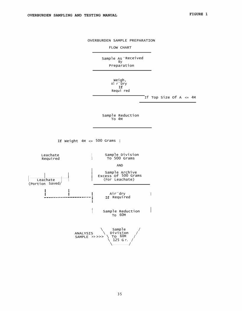
1.1 The purpose of overburden sample preparation is to provide thelaboratory with an analytical sample that accurately represents thechemical composition of the overburden sample. The preparationfacility may receive overburden samples that range in size from rockdust to solid core borings at the other end of the range. Theweight of the samples may range from less than a few hundred grams tomore than 50 pounds. The laboratory sample will be pulverized to amaximum particle size of 60M (mesh) or 0.25 millimeters.
1.2 The preparation methods discussed here are designed to addressprocesses of reducing (crushing) and dividing (splitting) theoverburden sample to generate the final analysis sample.
1.3 It is not in the scope of this procedure to address the health
and safety or regulatory aspects that may apply. These aspects mustbe considered by those performing the tasks inherent in this
procedure.
2. APPARATUS AND MATERIALS
2.1 The apparatus listed here is not the exclusive set of apparatusrequired for overburden sample preparation. Reference to a
particular product does not imply an endorsement of that product.Apparatus designed to accomplish similar results are also acceptable.
2.2 Jaw Crusher (Marcy 4 inch X 6inch): Capable of reducing thesample to a 4M (mesh) top size as defined by the Tyler system.
2.3 Riffle (splitter) (Humbolt 3962): Capable of dividing 4Mmaterial in a representative manner. Chute openings should be 3/8"to 3/4" wide.
2.4 Air-Dry Oven (Blue-M EM166F): Capable of maintaining an inside
temperature of 40 Deg. C. and air flow rate of 2 oven volumes per
minute.
2.5 Balance (Mettler PC24): Capable of weighing up to 20,000 grams
to the nearest gram.
2.6 Pulverizer (Holmes 500): Capable of reducing 4M material to a
size passing a 60M screen.
2.7 Screen (Gilson 4M, 8" round): Capable of determining the amount
of 4M material in a sample.
2.8 Containers: Capable of maintaining an air-tight seal around a
sample. One quart freezer bags are recommended for most samples.
31
OVERBURDEN SAMPLING AND TESTING MANUAL
3. IDENTIFICATION
3.1 Before any reduction or division is performed on any
overburden sample, it must identified by supervisory personnel as a
discrete sample. This may involve any or all of the followingsteps:
3.1.1 Verifying that the sample to be processed is anoverburden sample.
3.1.2 Checking the sample card identification against a drillhole log, if available.
3.1.3 Labelling the sample with a unique identificationsystem. This is usually accomplished by assigning a "LabNumber" to the sample. It is recommended practice to implementa labelling system that causes the identifying label to bephysically associated with the sample throughout the preparationprocedure.
3.1.4 A determination of the size consist of -the sample is tobe made so that the proper processing techniques are applied tothe sample.
3.1.5 The weight of the overburden sample is determined andrecorded.
3.1.6 Any unusual characteristics inherent in the sample are tobe noted and documented (sample very wet, etc.).
4. PROCEDURE
4.1 For overburden samples that are too wet to be processedthrough the first applicable stage of preparation, a grosssample air-drying procedure must be performed on the sample tolower the level of surface moisture in the sample. Dependingupon the size of the sample, the procedure described in 4.5
below may be suitable for this purpose. For larger samples, itmay be necessary to spread the sample on a clean surface (a tarpis recommended) and allow the sample to air dry. Air drying isaccomplished by allowing the sample to reside in the ambientconditions of a room for a period sufficient to lower thesurface moisture content to acceptable levels. (Overnight or1 2-16 hours is adequate for most samples.)
32
OVERBURDEN SAMPLING AND TESTING MANUAL
4.2 For overburden samples that have a "top-size" (95% or morepassing) that is greater than 4M (4.75 mm), the entire sample will
be reduced to a 4M or smaller top size. A "jaw" crusher or other
suitable device will be used for this purpose. Care must beexercised in this process to avoid loss of material. The crushingdevice is to be thoroughly cleaned with brushes and/or compressed
air between usage on different samples.
4.3 Samples that are received with a 4M or smaller top size orthat have been reduced to 4M are to be divided in a riffle or
other suitable dividing device to a weight of not less that 500grams. (Some overburden samples may have an initial weight of 500grams or less - these samples are not to be divided unlessleachate testing is anticipated.) The dividing device must bethoroughly cleaned between the processing of different samples.The 500 gram portion of 4M overburden Is now the subsample that,
after further processing, will be used to generate the laboratory60M sample.
4.4 For samples that have a weight of more than 500 grams, thematerial that is not used for the 500 gram subsample will be saved
for archiving. Because of storage considerations the archivedsample may be limited to 2000 grams by division (splitting).Samples that have an initial weight of 500 grams or less will not
have an archived 4M subsample, unless leachate testing isanticipated (See 4.3 above). Archived samples will be properly
identified and sealed in air-tight containers to retard
degradation.
4.5 Many of the 500 gram subsamples will require air-drying priorto further reduction (grinding or pulverizing). Excessive surface
moisture may cause caking and plugging of reduction equipment.For subsamples that may contain excessive surface moisture, an
air-drying procedure is implemented. For this purpose, an ovenwith the capability to maintain a temperature of 40 Degrees C andthe capability to effect 2 oven volume air changes per minute isrecommended, but not required. The air-drying procedure may be
also accomplished_ by spreading the sample in a pan or othersuitable container until it has dried sufficiently.
4.6 The 4M sample should now be ready for further size reduction
to 60M via the pulverization process. In cases when samples are
very hard (e.g. sandstone) reduction to sub-4M sizes may be
necessary, prior to pulverization. Most 500 gram subsamples may
be directly reduced to 60M. Until the entire subsample is reduced
to 60M, however, no division (splitting) is permitted. A
pulverizer or other suitable device is used to reduce the entire
500 gram subsample to 60M. This reduction device must be
thoroughly cleaned between usage on different samples.
33
OVERBURDEN SAMPLING AND TESTING MANUAL
4.7 The 60M subsample is then divided in a riffle or othersuitable device to a weight of approximately 125 grams. Theremainder of the 500 gram 60M material may be discarded. The 125gram lab sample is to be placed into an air-tight container whereit will remain during testing and storage. This container shouldhave a capacity such that the lab sample occupies no more than 3/4of the volume of the container.
4.8 The 60M sample is to be thoroughly mixed on a mechanicalmixing device (e.g., mixing wheel) or by a manual method designedto thoroughly mix the sample. This procedure is to be performedprior to any analytical testing and is to be repeated if asignificant time period has elapsed between analytical testing onany given sample.
4.9 The 125 gram subsample is delivered to the analytical lab forthe required testing. All pertinent information, such as drilllogs, is also delivered to the lab with the analytical sample.
34
I Sample ArchiveI I I Excess Of 500 GramsI Leachate I I I (For Leachate)(Portion Saved/
These procedures are modification of standard methods which have beenadapted for the analysis of Pennsylvanian overburden. The procedures arepresented in a step-by-step manner and include lists of needed equipment andreagents. The essentials for a Quality Assurance plan are given along withquality control measures which are required so that data submitted to thestate will be of a consistent quality.
A complete list of references which were used in the preparation of thismanual is given In the appendix.
This manual may contain procedures that involve hazardous materials,operations, and equipment. This manual does not purport to address all ofthe safety problems associated with their use. It is the responsibility ofwhoever uses this manual to consult and establish appropriate safety andhealth practices and determine the applicability of regulatory limitationsprior to use.
I. MAXIMUM POTENTIAL ACIDITY
Sulfur occurs in three basic forms in the coal bearing strata ofPennsylvania; sulfate sulfur, sulfide sulfur, and organic sulfur. Sulfatesulfur is usually only found in minor quantities and is frequently theresult of recent oxidation of sulfide sulfur. Sulfide sulfur is thepredominate sulfur species in the majority of overburden samples and is thespecies of greatest concern. The breakdown of pyrite, either chemically orbiologically, is the primary cause of acid mine drainage. Following commonconvention, sulfide sulfur will be referred to as pyrite. Organic sulfur is
only found in appreciable quantities in coal seams and in other carbonaceousrock strata.
Maximum Potential Acidity is the amount of acid that overburden couldproduce from the oxidation of the sulfide sulfur that it contains. In manycases, the total sulfur determination is an adequate estimation of thesulfide sulfur content and Is a easier test to perform. Organically boundsulfur is the only major form of sulfur which is generally considered not toproduce any acid.
1. TOTAL SULFUR
This section will cover In detail the instrumental and wet chemicalprocedures that are most prevalent. Included are the Eschka Method, BombWashing Method, and high temperature combustion methods that useInfrared absorption, iodimetric and acid base titration sulfur detectionsystems.
36
OVERBURDEN SAMPLING AND TESTING MANUAL
A. ESCHKA METHOD (ASTM D3177)
1. SCOPE AND APPLICATION
The Eschka Method is a gravimetric procedure that is appropriatefor the determination of total sulfur in all coals and overburden.
2. SUMMARY OF METHOD
A portion of the laboratory sample is heated with eschka mixture
to convert all sulfur to the sulfate form. The sulfate sulfur isthen leached with hot water and precipitated as barium sulfate.The total sulfur content is calculated from the weight of barium
sulfate.
3. INTERFERENCES AND PRECAUTIONS
3.1 Furnaces that have been used for ashing coal or any material
that would evolve large amounts of sulfur shall not be used forthe initial heating of the sample and eschka mixture. Sulfur is
absorbed during one heating cycle and will desorb readily, from
furnace elements and insulation during the next. Eschka mixture
can absorb this sulfur, thereby causing high results. For this
reason, a separate furnace shall be used for the initial eschka
sulfur burnoff.
3.2 The major reason for errors is poor analytical technique.
Specific areas of concern would be, 1) Improper mixing of the
sample with the eschka mixture and using an insufficient amount of
eschka mixture to cover the sample. 2) Poor transfer technique
which results in the physical loss of sample.
4. APPARATUS AND MATERIALS
4.1 MUFFLE FURNACE: Capable of maintaining 800°C. (refer to 3.1)
4.2 CRUCIBLES: 30 ml platinum or porcelain for igniting the sample
and 15 ml platinum, porcelain, or silica for igniting the barium
sulfate.
4.3 HOTPLATE: Size is dependent on sample quantity.
4.4 GLASSWARE: 200 and 400 ml beakers
4.5 FILTER PAPER: #40 and #42 Whatman or equivalent.
4.6 FILTER RACK AND FUNNELS
37
OVERBURDEN SAMPLING AND TESTING MANUAL
5. REAGENTS
5.1 All chemicals should be reagent grade and the water should beType Ill reagent water. (ASTM D1193)
5.2 BARIUM CHLORIDE SOLUTION: Dissolve 100 grams of BaCl2.2H20 inwater and dilute to a final volume of 1 liter.
5.3 ESCHKA MIXTURE: This is available commercially or can be madeby mixing 100 g. of anhydrous sodium carbonate with 200 g. ofcalcined magnesium oxide.
5.4 HYDROCHLORIC ACID (1:3): Dilute one volume of concentratedhydrochloric acid in 3 volumes of water.
5.5 METHYL ORANGE INDICATING SOLUTION: Dilute 5 ml of saturatedmethyl orange solution in 500 ml of water.
6. SAMPLE CONSIDERATIONS
6.1 This procedure does not require any special sample handlingconsiderations. The normal -60m sample is all that is required.
7. PROCEDURE
7.1 Weigh approximately 1 gram of sample to the nearest .1 mg. Mixthis thoroughly with approximately 3 grams of eschka mixture.(refer to 3.2)
7.2 Settle this mixture into a clean 30 ml crucible and covercompletely with approximately 2 gram of eschka mixture.
7.3 Heat the crucible in a muffle furnace (refer to 3.1) to atemperature of 500°0 C and hold for 1 /2 hour. Increase thetemperature to 800
0C and maintain for 2 hours. (Total time is
approximately 3 hours)
7.4 Transfer the contents to a 200 ml beaker and add 100 ml of hotwater. Rinse any remaining sample from the crucible into thebeaker with a stream of hot water. Periodically stir the sampleuntil it has been leached for 1/2 hour. (refer to 3.2)
7.5 Filter the supernatant, by decanting thru #40 Whatman, into a400 ml beaker.
7.6 Wash the residue in the beaker with hot water and decant as in7.5. Repeat this procedure a total of three times.
7.7 Wash the residue out of the beaker onto the filter paper,rinse the beaker twice and then wash the filter paper and residuean additional three times with hot water.
38
OVERBURDEN SAMPLING AND TESTING MANUAL
7.8 Adjust the volume of filtrate to approximately 250 ml and make
the solution slightly acidic with 1:3 HCI using the methyl orangesolution as the indicator, then add an additional 1 ml of 1:3 HCI.
7.9 Place the beakers on the hotplate and heat to boiling. Note:
The samples will evolve CO 2 gas prior to coming to a boil.
7.10 Slowly add 10 ml of barium chloride solution and continue toboil for 15 minutes. Cover the samples with a watch glass and let
them remain standing for several hours at a temperature just belowboiling. This will facilitate quantitative filtration of the
BaSO4 due to the formation of larger crystals.
7.11 After cooling, filter the precipitate using #42 Whatman
filter paper. Wash the beaker twice after triturating with a
policeman and then wash the filter paper and precipitate an
additional 8 times.
7.12 Transfer the filter paper, lightly folded, to a 15 ml
crucible and place in a cool muffle furnace.
7.13 Smoke off the filter paper b, heating to 500° C. After 1/2hour raise the temperature to 800 C and maintain for 1/2 hour.
7.14 Weigh the residue after the crucible has cooled.
8. CALCULATIONS
8.1 % SULFUR = (A-B) * 13.738 / C
A = weight of BaSO4 precipitateB = weight of blank residue
C = weight of sample
9. QUALITY CONTROL
9.1 A blank determination shall be made with every set of samples.
9.2 Precision shall be checked by the running of duplicates. A
minimum of 1 in 20 is required and 1 in 10 is considered optimum.
Acceptable precision is as follows:
% Sulfur less than 2 +/- .05%% Sulfur of 2 or more +/- .10%
9.3 Accuracy shall be checked by the monthly running of a SRM,
such as the NBS Sulfur in Coal Standards. Each standard specifies
an acceptable range of values that can be used to judge an
analyst's performance.
39
OVERBURDEN SAMPLING AND TESTING MANUAL
B. BOMB WASHING METHOD (ASTM D3177)
1. SCOPE AND APPLICATION
The Bomb Washing method of determining total sulfur is applicableto all coals without modifications and to all overburden if acombustion aid is used.
2. SUMMARY OF METHOD
A portion of the laboratory sample is combusted in an oxygenbomb, the contents of the bomb are washed into a beaker,neutralized and filtered. The sulfur in the filtrate isprecipitated as BaSO4, filtered, ashed and the BaSO4 residueweighed to determine the amount of sulfur in the sample. Mostoverburden samples will not sustain combustion so a combustion aidmust be used to quantitatively determine the sulfur content.
3. INTERFERENCES AND PRECAUTIONS
3.1 This procedure is dependent on good analytical technique foraccurate and precise results. Specific areas of concern are:releasing the bomb pressure too rapidly and incomplete washing ofthe bomb interior and valves. Both of these errors w i l l result inan underestimation of the total sulfur content.
4. APPARATUS AND MATERIALS
4.1 COMBUSTION BOMB: Parr #1108 or equivalent
4.2 CRUCIBLES: 15 ml platinum, porcelain, or silica for ignitingthe barium sulfate.
4.3 HOTPLATE: Size is dependent on sample quantity.
4.4 GLASSWARE: 200 and 400 ml beakers
4.5 FILTER PAPER: #40 and #42 Whatman or equivalent.
4.6 FILTER RACK AND FUNNELS
4.7 COMBUSTION CRUCIBLE: Parr #43AS or equivalent
5. REAGENTS
5.1 All chemicals should be reagent grade and the water should beType Ill reagent water.
5.2 BARIUM OHLOR I DE SOLUTION: Dissolve 100 grams of BaCl2.2H20 inwater and dilute to a final volume of 1 liter.
40
OVERBURDEN SAMPLING AND TESTING MANUAL
5.3 HYDROCHLORIC ACID (1:3): Dilute one volume of concentrated
hydrochloric acid in 3 volumes of water.
5.4 METHYL ORANGE INDICATING SOLUTION: Dilute 1 ml of saturated
solution in 500 ml of water.
5.5 COMBUSTION AID: mineral oil
5.6 NaOH SOLUTION: Dissolve 20 grams of NaOH in 1 liter of water.
6. SAMPLE CONSIDERATIONS
6.1 This procedure does not require any special sample handlingconsiderations. The normal -60m sample is all that is required.
7. PROCEDURE
7.1 Weigh approximately 1 gram of sample, to the nearest .1 mg.,
into a clean combustion capsule.
a. For samples that will not sustain combustion, reduce theweight of the sample to .75 gram and add .75 gram of mineral oil.
After the oil has soaked into the sample continue with 7.2. Thesample weight may need to be decreased further if the sample does
not completely react when the oil burns.
7.2 Thoroughly wash the bomb, including through the valves, with
water.
7.3 Follow the manufacturers recommended procedure for loading thebomb and charging with oxygen.
7.4 Immerse the bomb in water, connect the firing circuit and firethe bomb. Wait a minimum of five minutes before removing the bomb
from the water.
7.5 Rinse the bomb head with water and dry with a clean towel.
7.6 Release the pressure in the bomb at a very slow and evenrate.(1 minute minimum) A loss of sulfur will result if the
pressure is released to rapidly.
7.7 Wash the contents of the bomb into a 400 ml beaker using
methyl orange solution. Rinse the capsule and all bomb parts. Be
especially careful to completely wash through all valves. The
methyl orange solution will stay yellow in the bomb when it iscompletely washed. Transfer all washings to the beaker.
41
OVERBURDEN SAMPLING AND TESTING MANUAL
7.8 Neutralize the washings with dilute NaOH to the methyl orangeendpoint. Heat to boiling and then filter thru #40 Whatman filter
paper into a 400 ml beaker. Wash the beaker twice and the filterpaper an additional four times.
7.9 Adjust the volume of filtrate to approximately 250 ml and makethe solution slightly acidic with 1:3 HCI using the methyl orangesolution as the indicator, then add an additional 1 ml. of 1:3 HCI.
7.10 Place the beakers on the hotplate and heat to boiling.
7.11 Slowly add 10 ml of barium chloride solution and continue toboil for 15 minutes. Cover the samples with a watch glass and letthem remain standing for several hours at a temperature just belowboiling. This will facilitate quantitative filtration of the BaSO 4
due to the formation of larger crystals.
7 12 After cooling, filter the precipitate using #42 Whatmanfilter paper. Wash the beaker twice after triturating with apoliceman and then wash the filter paper and precipitate anadditional 8 times.
7.13 Transfer the filter paper, lightly folded, to a 15 mlcrucible and place in a cool muffle furnace.
7.14 Smoke off the filter pager by heating to 500° C. After 1/2hour raise the temperature to 800 C and maintain for 1/2 hour. Ifany carbon remains, retrn the crucible to the furnace for anadditional 1/2 hour at 800' C.
7.15 Weigh the residue after the crucible has cooled.
7.16 A blank determination is made by using the above procedure on.75 gram of mineral oil.
8. CALCULATIONS
8.1 % SULFUR = (A-B) * 13.738 / C
A = weight of BaSO4 precipitateB = weight of blank residueC = weight of sample
9. QUALITY CONTROL
9.1 A blank determination shall be made with every set of samples.
42
OVERBURDEN SAMPLING AND TESTING MANUAL
9.2 Precision shall be checked by the running of duplicates. A
minimum of 1 in 20 is required and 1 in 10 is considered optimum.Acceptable precision is as follows:
% Sulfur less than 2 +/- .05%
% Sulfur of 2 or more +/- .10%
9.3 Accuracy shall be checked by the monthly running of a SRM,such as the IBS Sulfur in Coal Standards. Each standard specifies
an acceptable range of values that can be used to judge ananalyst's performance.
43
OVERBURDEN SAMPLING AND TESTING MANUAL
C. HIGH TEMPERATURE COMBUSTION, INFRARED ABSORPTION (ASTM D 4239)
1. SCOPE AND APPLICATION
The high temperature instrumental technique of total sulfur
analysis is applicable to all coal samples and, if prescribedmeasures are followed, to overburden samples.
2. SUMMARY OF METHOD
A portion of the laboratory sample is combusted in a stream ofoxygen at a temperature of approximately 1350 °C. The resultantS02 gas is detected by infrared absorption and compared to astandard calibration.
3. INTERFERENCES AND PRECAUTIONS
3.1 Samples of limestones and highly calcareous strata can
absorb S02 gas being evolved during combustion and thereby causel ow results. Operationally this problem can be minimized with theuse of an accelerator such as vanadium pentoxide.
3.2 Comparative techniques such as this are only as good as thestandards that are being used to calibrate the instrument so it isessential that only the highest quality standards be used.
3.3 Preventive maintenance is essential for the proper operationof this instrument.
4. APPARATUS AND MATERIALS -
4.1 LECO SC—32 or equivalent
4.2 SAMPLE BOATS
4.3 GLASS WOOL
5. REAGENTS
5.1 VANADIUM PENTOXIDE: reagent grade
5.2 OXYGEN: 99.999% purity
5.3 MAGNESIUM PERCHLORATE: reagent grade, 10m x 20m.
5.5 SECONDARY STANDARDS: Those standards that are purchased orprepared and which have been validated with Primary Standards.
44
OVERBURDEN SAMPLING AND TESTING MANUAL
a. VALIDATION PROCEDURE FOR PURCHASED SECONDARY STANDARDS
I. Use the manufacturer's recommended procedure to calibrate theinstrument with an NBS primary standard of approximately 3.00% sulfur.
This calibration should be confirmed by analyzing the 3.00% sulfur
standard to make sure that its determined value falls within itscertified range of values. If the determined value is outside thecertified range, repeat the process. After acceptable calibration, maketwo determinations for the secondary standard. The secondary standardis acceptable if both of the obtained values are within the certified
range as stated for that standard. If the values are not within thatrange, that secondary standard is not suitable for use with thisprocedure.
b. IN-HOUSE PREPARATION OF SECONDARY STANDARDS
i. Twenty sulfur determinations shall be performed using any one of theproposed methodologies: eschka, bomb washing, or high
temperaturecombustion. These twenty determinations shall consist of tendeterminations for the proposed secondary standard and tendeterminations of a primary standard of comparable sulfur content. If
one of the high temperature combustion techniques is used, instrumentcalibration shall be performed as described in 5.5.a.i. Also, if a high
temperature combustion procedure is used, the running of samples shallbe alternated, primary then secondary, until the required number of
determinations has been made. The corresponding averages and standarddeviations shall be computed for the ten (10) primary determinations
and the ten (10) proposed secondary determinations.
ii. Data validation of primary standard determinations - All ten values
as determined for the primary standard shall fall within the certifiedrange of the standard. I f any of the values fail to be within thecertified range, step 5.5.b.i must be repeated.
iii. Data validation of proposed secondary standard determinations- Theten values as determined for the proposed secondary standard shall meet
the following criterion: two standard deviations shall be equal to orless than one-half the repeatability interval for the given methodology
(i.e. 2 S.D. < I(r)/2 ). The repeatability interval shall be defined
based on the average value (x) of the 10 proposed secondary standarddeterminations as fol lows:
If the proposed secondary standard data set fails to meet thiscriterion ( 2 S.D. _< I(r)/2 ) then step 5.5.b.i must be repeated.
iv. Certified range of the proposed secondary standard- Assuming boththe primary and secondary data sets satisfy the required validationcriteria, the certified value of the proposed secondary standard shallbe calculated as follows:
c = x + (p - px) where
c = certified value of secondary standard
x = computed average of the ten secondary standard determinationsp = certified average of primary standard
px = computed average of the ten primary standard determinations
The certified range of the secondary standard shall be computed asfollows:
cr = c ± I(r)/2 where
cr = certified range of secondary standardc = certified value of secondary standardI(r) = repeatability interval as defined in 5.5.b.iii
6. SAMPLE CONSIDERATIONS
6.1 This procedure does not require any special sample handlingconsiderations. The normal -60m sample is all that is required.
7. PROCEDURE
7.1 Insure that the instrument is functioning properly. (Refer tosection # 9 on Quality Control)
7.2 Calibrate the instrument at the 3.0 % +/- 0.5% sulfur levelusing the manufacturer's recommended procedure.
46
OVERBURDEN SAMPLING AND TESTING MANUAL
7.3 Verify that the instrument is properly calibrated by running a
secondary standard with a nominal value of 1 or 2 % sulfur.
Compare the obtained value to the certified range for that
standard.
7.4 For each sample, tare a sample boat and then weigh between
0.300 and 0.400 grams of sample.
a. I f the sample has a Fizz rating of 2 or 3, (refer to section
II, Neutralization Potential), the sample has to be covered
with vanadium pentoxide to insure that all sulfur is releasedfrom the sample and not trapped by the calcium carbonate
present in the sample.
7.5 Verify that the instrument is properly calibrated by running a
secondary standard after each group of samples.
a. Maximum group = 20 samples
b. Optimum group = 10 samples
c. If the standard is outside the certified limits repeat steps
7.2 and 7.3. If the standard is still outside the certifiedlimits the instrument will have to be recalibrated. Reanalyze
the previous group of samples after the conditions of 7.3 have
been met.
d. I f the standard is within the certified range continue with
the next group of samples.
7.6 Replace the first moisture trap after every 75 runs or
whenever the top 1/3 of the trap is saturated.
8. CALCULATIONS
8.1 % Sulfur is calculated directly with a properly calibrated
instrument.
9. QUALITY CONTROL
9.1 Prepare the instrument for analysis by performing the
recommended weekly maintenance.
a. Perform an oxygen system leak test
b. Clean the main fan filter
c. Replace the liner and boat stops after every 1000 runs.
47
OVERBURDEN SAMPLING AND TESTING MANUAL
d. Verify the calibration with a primary standard.
e. Inspect the dust traps and replace if necessary.
9.2 Prepare the instrument for analysis by performing therecommended daily maintenance.
a. Clean the collection tube, boat stop and delivery tube
b. Replace the first moisture trap.
c. Inspect the second moisture trap and replace if necessary.
d. Check the lance tube for proper operation.
e. Check the gas pressures and flow rates and adjust tospecifications if necessary.
f. Verify that all system constants are correct.
9.3 Precision shall be checked by the running of duplicates. Aminimum of 1 in 20 is required but 1 in 10 is considered optimum.Acceptable precision is as follows:
a. 0.03 + 0.04 * X where X = the average of the two results.
9.4 Accuracy shall be checked by the weekly running of a standardreference material such as the NBS Sulfur in Coal Standards. Eachstandard specifies an acceptable range of values that can be usedto judge the acceptability of secondary standards as well as ananalyst's performance.
D. HIGH TEMPERATURE COMBUSTION, IODIMETRIC TITRATION (ASTM D 4329)
1. SCOPE AND APPLICATION
The high temperature instrumental technique of total sulfuranalysis is applicable to all coal samples and, if prescribedmeasures are followed, to overburden samples.
2. SUMMARY OF METHOD
A portion of the laboratory sample is combusted in a stream ofoxygen at a temperature of approximately 1350 °C. The resultantS02 gas is scrubbed from the gas stream and titrated with iodinesolution. The percent sulfur is calculated from a standardcalibration.
48
OVERBURDEN SAMPLING AND TESTING MANUAL
3. INTERFERENCES AND PRECAUTIONS
3.1 Refer to section 3 of Infrared Absorption.
3.2 Chlorine and iron concentrations in the samples that are
dissimilar to those in the standards used for the instrument
5.5 SECONDARY STANDARDS: Those standards that are purchased orprepared and which have been validated with Primary Standards.
Refer to this section C.1. 5:5.
6. SAMPLE CONSIDERATIONS
6.1 This procedure does not require any special sample handlingconsiderations. The normal -60m sample is all that is required.
7. PROCEDURE
7.1 Insure that the instrument is functioning properly by
performing preventive maintenance as recommended by the
manufacturer.
7.2 Calibrate the instrument at the 3.0 % +/- 0.5 sulfur levelusing the manufacturer's recommended procedure.
7.3 Verify that the instrument is properly calibrated by running asecondary standard with a nominal value of 1 or 2 % sulfur.
Compare the obtained value to the certified range for that
standard.
49
OVERBURDEN SAMPLING AND TESTING MANUAL
7.4 For each sample, tare a sample boat, then weigh approximately0.150 grams and proceed with the analysis.
a. I f the sample has a Fizz rating of 2 or 3, (refer to sectionII, Neutralization Potential ), the sample has to be covered
with vanadium pentoxide to insure that all sulfur is releasedfrom the sample and not trapped by the calcium carbonatepresent in the sample.
7.5 Verify that the instrument is maintaining calibration byrunning a secondary standard after each group of samples.
a. Maximum group = 20 samples
b. Optimum group = 10 samples
c. If the standard is outside the certified limits repeat steps7.1. If the standard is still outside the certified limits theinstrument will have to be recalibrated. Reanalyze the previousgroup of samples after the conditions of 7.3 have been met.
d. If the standard is within the certified range continue withthe next group of samples.
8. CALCULATIONS
8.1 % Sulfur is calculated directly with a properly calibratedinstrument.
9. QUALITY CONTROL
9.1 Precision shall be checked by the running of duplicates. Aminimum of 1 in 20 is required but 1 in 10 is considered optimum.Acceptable precision is as follows:
a. 0.08 * X where X = the average of the two results.
9.2 Accuracy shall be checked by the weekly running of a standardreference material such as the PBS Sulfur in Coal Standards. Eachstandard specifies an acceptable range of values that can be usedto judge the acceptability of secondary standards as well as ananalyst's performance.
50
OVERBURDEN SAMPLING AND TESTING MANUAL
E. HIGH TEMPERATURE COMBUSTION, ACID BASE TITRATION (ASTM D 4239)
1. SCOPE AND APPLICATION
The high temperature instrumental technique of total sulfur
analysis is applicable to all coal samples and, if prescribedmeasures are followed, to overburden samples.
2. SUMMARY OF METHOD
A portion of the laboratory sample is combusted in a stream of
oxygen at a temperature of approximately 1350 C. The resultant
gas is absorbed in a solution of H202 and forms dilute. solutionsof H2SO4 and HCI which is titrated with dilute NaOH to determine
5.6 SECONDARY STANDARDS: Those standards that are purchased orprepared and which have been validated with Primary Standards.
Refer to this section B.1. 5.5.
6. SAMPLE CONSIDERATIONS
6.1 This procedure does not require any special sample handling
considerations. The normal -60m sample is all that is required.
5 1
OVERBURDEN SAMPLING AND TESTING MANUAL
7. PROCEDURE
7.1 Insure that the instrument is functioning properly byperforming preventive maintenance as recommended by themanufacturer.
7.2 Verify that the instrument is properly calibrated by running asecondary standard with a nominal value of 1 or 2 % sulfur.Compare the obtained value to the certified range for thatstandard.
7.3 For each sample, tare a sample boat, then weigh approximately0.400 grams and proceed with the analysis.
a. I f the sample has a Fizz rating of 2 or 3, (refer to sectionII, Neutralization Potential), the sample has to be coveredwith vanadium pentoxide to Insure that all sulfur is releasedfrom the sample and not trapped by the calcium carbonatepresent in the sample.
7.4 Verify that the instrument is maintaining calibration byrunning a secondary standard after each group of samples.
a. Maximum group = 20 samples
b. Optimum group = 10 samples
c. If the standard is outside the certified limits repeat steps7.1. If the standard is still outside the certified limits theinstrument will have to be recalibrated. Reanalyze the previousgroup of samples after the conditions of 7.2 have been met.
d. If the standard is within the certified range continue withthe next group of samples.
8. CALCULATIONS
8.1 % Sulfur is calculated directly when an exact weight is usedfor all standards and samples.
8.2 The % Sulfur needs to be corrected for %CI if optimum accuracyis to be obtained.
9.1 Precision shall be checked by the running of duplicates. A
minimum of 1 in 20 is required but 1 in 10 is considered optimum.
Acceptable precision is as follows:
a. 0.06 + 0.03 * X where X = the average of the two results.
9.2 Accuracy shall be checked by the weekly running of a standardreference material such as the IBS Sulfur in Coal Standards. Eachstandard specifies an acceptable range of values that can be usedto judge the acceptability of secondary standards as well as ananalyst's performance.
53
OVERBURDEN SAMPLING AND TESTING MANUAL
2. FORMS OF SULFUR
This section covers in detail the procedures which are used to quantify
the amount of sulfate, sulfide and organic sulfur in coal and
overburden. The ASTM procedure that is presented is applicable for coalbut it is not always appropriate for overburden. The EPA procedure isadequate for coal and overburden but is not as precise as thecombination procedure which uses the best features of the ASTM and EPAmethods.
A. ASTM STANDARD METHOD D2492
1. SCOPE AND APPLICATION
The ASTM Method D2492 is appropriate for the determination ofthe forms of sulfur in all coals but was not intended to be usedwith any other sample matrix. Mineralogies can exist inoverburden that can cause an over estimation of the pyriticcontent of some samples. This is possible since the ASTMprocedure assumes that all iron extracted with nitric acid,after the sample has been leached with hydrochloric acid, is ofpyritic origin.
2. SUMMARY OF METHOD
A portion of the laboratory sample is heated with a dilutesolution of HCI to remove sulfate sulfur and to remove Ironthat would interfere with the pyritic iron determination.Thesulfate sulfur content is calculated from the weight of bariumsulfate which is precipitated from the HCI extraction filtrate.Pyritic and organic sulfur remain in the sample residue sinceneither are soluble in hydrochloric acid. The sample residuefrom the HCI extraction is then extracted with dilute nitricacid to dissolve the pyrite in the sample. The iron in thisextract is quantified by titration or by atomic absorptionspectrophotometry. This value is used to calculate the amount ofpyritic sulfur in the sample. Organic sulfur is calculated fromthe difference between the total sulfur determination and thesum of the sulfate and pyritic sulfurs.
3. INTERFERENCES AND PRECAUTIONS
3.1 This procedure was developed solely for the analysis of coaland may not be appropriate for the analysis of some overburdensamples.
54
OVERBURDEN SAMPLING AND TESTING MANUAL
3.2 Low results may be obtained on the determination of pyritic
iron due to the incomplete dissolution of the pyrite if a large
sample size is used with a sample of high pyritic sulfur
content. This problem can easily be overcome by choosing
reasonable sample weights and by further size reduction of
samples with exceptionally high pyritic sulfur contents.
4. APPARATUS AND MATERIALS
4.1 MUFFLE FURNACE : Capable of maintaining 800°C.
4.2 CRUCIBLES: 1 5 ml platinum, porcelain, or silica for igniting
the barium sulfate.
4.3 HOTPLATE: Size is dependent on sample quantity.
4.4 GLASSWARE: 150 and 400 ml beakers
4.5 FILTER PAPER: #4, #40 and #42 Whatman or equivalent.
4.6 FILTER RACKS AND FUNNELS:
4.7 ATOMIC ABSORPTION SPECTROPHOTOMETER:
4.8 Refer to the total sulfur technique that w i l l be used toanalyze the subsamples.
5. REAGENTS
5.1 All chemicals should be reagent grade and the water should
be Type III reagent water.
5.2 BARIUM CHLORIDE SOLUTION: Dissolve 100 grams of BaCl2.2H20in water and dilute to a final volume of 1 liter.
5.3 HYDROCHLORIC ACID (40%) : Dilute two volumes of
concentrated hydrochloric acid in 3 volumes of water.
5.4 METHYL ORANGE INDICATING SOLUTION: Dilute 5 ml of
saturated solution in 500 ml of water.
5.5 AMMONIA HYDROXIDE SOLUTION (1:1): Dilute one volume of
concentrated NH40H with one volume of water.
5.6 BROMINE WATER: saturate water with liquid bromine and store
in a dark bottle under a hood.
5.7 METHANOL (25%): Dilute one volume of methanol in three
volumes of water.
55
OVERBURDEN SAMPLING AND TESTING MANUAL
5.8 NITRIC ACID(12.5%): Dilute 1 volume of concentrated nitricacid in seven volumes of water.
5.9 LANTHANUM SOLUTION: Dissolve 175 grams of LaCI3 or 265 gramsof LaCI3.7H20 in water and dilute to 1 liter.
5.10 Refer to the total sulfur technique that will be used toanalyze the subsamples.
6. SAMPLE CONSIDERATIONS
6.1 This procedure does require special sample handlingconsiderations. The normal -60m sample is not adequate forsamples with high sulfur contents. Samples that contain morethan 8% sulfur need to be ground to pass a 200m screen in orderto insure a complete extraction of the pyritic iron.
7. PROCEDURE
7.1 Sample weights are based on the following:
% Total Sulfur
Weight of analysis sample
< 2.0 % 1.0 gram2.0 to 4.0 % 0.5 gram4.0 to 8.0 % 0.3 gram> 8.0 % 0.15 gram
7.2 Analyze the sample for sulfate sulfur.
a. Weigh an amount of sample based on the chart in 7.1,record the weight to the nearest .1 mg.
b. Transfer the sample to a 150 ml beaker, wet with 25%methanol and add 50 ml of 40% HCI.
c. Boil gently for 30 minutes and remove from the hotplate.
d. Filter thru #40 Whatman filter paper into a 400 mlbeaker. Rinse the beaker twice and the residue six timeswith cold water. Save the residue and filter paper for thepyritic iron determination. (refer to 7.3)
e. Add approximately 5 ml of bromine water to the filtrateand boil for 5 minutes. This step insures that all ironpresent in the filtrate will be oxidized to the ferric formfor subsequent removal as ferric hydroxide. Heat for a fewminutes to insure a complete reaction.
56
OVERBURDEN SAMPLING AND TESTING MANUAL
f. Stir in 25 ml of 1:1 NH40H to precipitate any iron andmanganese in the filtrate.
g. Filter into a 400 ml beaker using #4 Whatman filterpaper. Rinse the beaker twice and the residue six times withhot water. Discard the filter paper and residue.
NOTE: If a large amount of manganese was dissolved with theiron, as evidenced by a fine textured brown precipitateinstead of an orange colloidal precipitate, #42 Whatman
filter paper will have to be used to effectively remove themetals. Some samples have such a high concentration of ironand manganese that steps (e) thru (g) have to be repeated inorder that a clear filtrate will be obtained.
h. Adjust the volume of filtrate to approximately 250 ml andmake the solution slightly acidic with 40% HCI using themethyl orange solution as the indicator, then add anadditional 1 ml of 40% HCI.
i. Place the beakers on the hotplate and heat to boiling.
j. Slowly add 10 ml of hot barium chloride solution and
continue to boil for 15 minutes. Cover the samples with awatch glass and let the samples remain standing for severalhours at a temperature just below boiling. This willfacilitate quantitative filtration of the BaSO4 due to theformation of larger crystals.
k. After cooling, filter the precipitate using #42 Whatmanfilter paper. Rinse the beaker twice with water aftertriturating with a rubber policeman. Rinse the filter paperand precipitate an additional 8 times.
I.Transfer the filter paper, lightly folded, to a 15 ml
crucible and place in a cool muffle furnace.
m. Smoke off the filter paper by heating to 500° C After
1 /2 hour raise the temperature to 8000 C and maintain for
1/2 hour. If any carbon remains, return the crucible to the
furnace for an additional 1/2 hour at 8000 C.
n. Weigh the barium sulfate after the crucible has cooled.
7.3 Analyze the residue from 7.2d for pyritic iron.
a. Return the filter paper and residue from 7.2d to the 150
ml beaker that was used for the HCI extraction.
5 7
OVERBURDEN SAMPLING AND TESTING MANUAL
b. Add 50 ml of 1 2.5% nitric acid to the beaker and stirthoroughly until the filter paper has disintegrated. Coverthe beaker with a watch glass and either boil gently for 1/2hour (fume hood required.) or let the sample stand overnightat room temperature.
c. Filter the sample into a 100 ml volumetric flask, washingthe beaker twice and the filter paper plus residue anadditional six times.
I. If an air/acetylene flame is going to be used, add 10 mllanthanum solution before diluting to volume. The lanthanumsolution is added to minimize interferences that can occurin the relatively cool air/acetylene flame. An easieralternative is to simply use the hotter nitrousoxide/acetylene flame for the elimination of interferences.
d. Prepare standards that have the same acid concentrationas the samples and which have iron concentrations thatbracket the samples. Add 10 ml of lanthanum solution per 100ml of standard if the air /acetylene flame is to be used.
e. Set the atomic absorption spectrophotmeter operatingconditions according to the manufacturers recommendations.Let the light source and the flame reach equilibrium priorto running any samples. (approx. 15 min.)
f. Determine the concentration of iron in the samples to thenearest 0.1 mg/I.
g. Refer to ASTM volume 05.05, Gaseous Fuels; Coal and Coke,D2492 Forms of sulfur in Coal if the titration technique forthe iron determination is used.
7.4 Analyze the sample for total sulfur using one of theprocedures that are explained in this manual.
8. CALCULATIONS
8.1 % SULFATE SULFUR = (A-B) * 13.738 / C
A = weight of BaSO4 precipitateB = weight of blank residueC = weight of sample
8.2 % PYRITIC SULFUR = A * B * .01148 / C
A = ppm of iron as determined by AASB = dilution factorC = weight of sample
58
OVERBURDEN SAMPLING AND TESTING MANUAL
8.3 % ORGANIC SULFUR = A - (B + C )
A = % TOTAL SULFURB = % SULFATE SULFURC = % PYRITIC SULFUR
9. QUALITY CONTROL
9.1 Precision shall be checked by the running of duplicates. Aminimum of 1 in 20 is required but 1 in 10 is consideredoptimum. Acceptable precision is as follows:
% S < 2.0 % % S > 2.0 %
Sulfate sulfur +/- 0.02 % +/- 0.02 %
Pyritic sulfur +/- 0.05 % +/- 0.10 %
Organic sulfur +/- 0.10 % +/- 0.20 %
9.2 Currently accuracy can not be determined since there are no
NBS certified standards available.
B. MODIFIED EPA METHOD
1. SCOPE AND APPLICATION
This procedure is applicable to all coals and overburden withthe following qualifications: 1) The precision of the sulfate
sulfur determination is limited to twice the total sulfur
precision which means that the possible error could be an orderof magnitude greater than the actual sulfate sulfur content. 2)
The organic sulfur content could be over estimated since any
unreacted pyrite will be determined as organic sulfur.
Modifications must be made to the procedure to ensure completedissolution of the pyritic sulfur. Both of these errors would in
most cases cause an underestimation of the pyritic sulfurcontent and therefore would underestimate the maximum potential
acidity.
2. SUMMARY OF METHOD
In this procedure three portions of the laboratory sample are
analyzed for sulfur. One portion is analyzed without any
pretreatment to determine the total sulfur content of thesample. A second portion is analyzed for pyritic plus organic
sulfur after the sample has been leached with dilute
hydrochloric acid. The third portion is analyzed for organic
sulfur after the sample has been leached with dilute nitric
acid. The concentrations of the forms of sulfur are then
calculated from the three results.
59
OVERBURDEN SAMPLING AND TESTING MANUAL
3. INTERFERENCES AND PRECAUTIONS
3.1 Low results may be obtained for the calculated pyriticsulfur if a large sample size is used with a sample of highpyritic content, due to possible positive errors in thedeterminations of sulfate and organic sulfur.
4. APPARATUS AND MATERIALS
4.1 FUNNEL RACK:
4.2 BEAKERS: 100 ml pyrex
4.3 FILTER PAPER: glass fiber or cellulose, depending on whichtotal sulfur procedure is chosen.
4.4 Refer to the total sul fur technique that w i l l be used toanalyze the subsamples.
5. REAGENTS
5.1 All chemicals should be reagent grade and the water shouldbe Type III reagent water.
5.2 HYDROCHLORIC ACID (40%): Dilute 2 parts of concentrated HCIin 3 parts of water.
5.3 NITRIC ACID (12.5%): Dilute 1 part of concentrated HNO3 in 7parts of water.
5.4 Nessler's Reagent
5.5 Silver Nitrate Solution (10%)
5.6 Refer to the total sulfur technique that w i l l be used toanalyze the subsamples.
6. SAMPLE CONSIDERATIONS
6.1 This procedure requires special sample handlingconsiderations. The normal -60m sample is not adequate forsamples with high sulfur contents. Samples containing more than8% sulfur shall be ground to pass a 200m screen in order toinsure a complete extraction of the pyritic iron.
7. PROCEDURE
7.1 Analyze the sample for total sulfur using one of theprocedures in this manual.
60
OVERBURDEN SAMPLING AND TESTING MANUAL
7.2 Analyze the sample for pyritic plus organic sulfur.
a. Weigh approximately 0.5 gram of sample,to the nearest 0.1mg, into a clean 100 ml beaker.
b. Add 50 ml of 40% HCI to the beaker, cover with a watch
glass and boil gently for 1/2 hour.
c. Filter the sample, washing the beaker twice and theresidue an additional six times. Discard the filtrate.
I. Use # 40 Whatman if you use the Eschka method foranalyzing the residue. Use glass fiber filters if you useany of the high temperature combustion methods to analyzethe residue.
ii. If the iodimetric or the acid base titration techniquesare to be used then the filtrate will have to be tested forthe presence of chlorides with 10% AgNO3 solution. Ifchlorides are detected, wash the residue until the filtratedoes not produce a white precipitate. upon the addition ofAgNO3.
d. Dry the sample and determine the sulfur content using oneof the total sulfur methods. The bomb washing method wouldbe cumbersome due to the mass of the filter paper.
7.3 Analyze the sample for organic sulfur.
a. Weigh approximately 0.5 gram of sample,to the nearest 0.1mg, into a clean 100 ml beaker.
b. Add 50 ml of 1 2.5% nitric acid to the beaker and stirthoroughly until the filter paper has disintegrated. Coverthe beaker with a watch glass and either boil gently for 1/2hour (fume hood required) or let the sample stand overnightat room temperature.
c. Filter the sample, washing the beaker twice and the
residue an additional six times.
i. Use # 40 Whatman if you use the Eschka method for
analyzing the residue. Use glass fiber filters if you useany of the high temperature combustion methods to analyzethe residue.
ii. If the iodimetric or the acid base titration totalsulfur method is to be used to analyze the residue then the
filtrate will have to be tested for the presence of nitrates
with Nessler's reagent. If nitrates are detected, wash theresidue until the filtrate does not turn yellow upon theaddition of Nessler's reagent. (Allow one minute for the
reaction.)61
OVERBURDEN SAMPLING AND TESTING MANUAL
d. Dry the sample and determine the sulfur content using oneof the total sulfur techniques. The initial sample weightfrom 7.3a must be used in all calculations. The bombwashing method would be cumbersome due to the mass of thefilter paper.
8. CALCULATIONS
8.1 Calculate the forms of sulfur from the results of the threedeterminations from section 7 as follows:
9.1 Precision shall be checked by the running of duplicates. Aminimum of 1 in 20 is required but 1 in 10 is consideredoptimum. Acceptable precision is as follows:'
9.2 Currently accuracy can not be determined since there are noNBS certified standards available.
C. ASTM/EPA COMBINATION METHOD
1. SCOPE AND APPLICATION
This procedure is applicable to all coals and overburden samplescommon to Pennsylvania.
2. SUMMARY OF METHOD
The sulfate sulfur content is accurately determined using agravimetric procedure that is essentially ASTM method D2492. Theorganic sulfur content is determined on a subsample that hasbeen leached with nitric acid using a procedure that is close tothe EPA procedure. The sulfide sulfur content of the sample iscalculated from the difference of the total sulfur and the sumof the sulfate and organic sulfurs.
3. INTERFERENCES AND PRECAUTIONS
The modifications of the ASTM and EPA methods contained in thisprocedure minimize the errors that were possible with thoseprocedures.
62
OVERBURDEN SAMPLING AND TESTING MANUAL
4. APPARATUS AND MATERIALS
4.1 MUFFLE FURNACE : Capable of maintaining 800°C.
4.2 CRUCIBLES: 15 ml platinum, porcelain, or silica for ignitingthe barium sulfate.
4.3 HOTPLATE: Size is dependent on sample quantity.
4.4 GLASSWARE: 150 and 400 ml beakers.
4.5 FILTER PAPER: Glass fiber #4, #40 and #42 Whatman or
equivalent.
4.6 FILTER RACK AND FUNNELS:
4.7 Refer to the total sul fur technique that will be used toanalyze the subsample for organic sulfur.
5. REAGENTS
5.1 All chemicals should be reagent grade and the water should
be Type Ill reagent water.
5.2 BARIUM CHLORIDE SOLUTION: Dissolve 100 grams of BaCl2.2H2Oin water and dilute to a final volume of 1 liter.
5.3 HYDROCHLORIC ACID (40%): Dilute two volumes ofconcentrated hydrochloric acid in 3 volumes of water.
5.4 METHYL ORANGE INDICATING SOLUTION: Dilute 5 ml of
saturated solution in 500 ml of water.
5.5 AMMONIA HYDROXIDE SOLUTION (1:1): Dilute one volume ofconcentrated NH4OH with one volume of water.
5.6 BROMINE WATER: saturate water with liquid bromine and storein a dark bottle under a hood.
5.7 METHANOL (25%): Dilute one volume of methanol in three
volumes of water.
5.8 NITRIC ACID(12.5%): Dilute 1 volume of concentrated nitricacid in seven volumes of water.
5.9 Refer to the total sulfur technique that will be used toanalyze the subsample for organic sulfur.
63
OVERBURDEN SAMPLING AND TESTING MANUAL
6. SAMPLE CONSIDERATIONS
6.1 This procedure does require special sample handlingconsiderations. The' normal -60m sample is not adequate forsamples with high sulfur contents. Samples that contain more
than 8% sulfur shall be ground to pass a 200m screen in order to
insure a complete extraction of the pyritic iron.
7. PROCEDURE
7.1 Analyze the sample for total sulfur using one of the
procedures that are explained in this manual.
7.2 Analyze the sample for sulfate sulfur.
a. Weigh approximately 2 grams of sample and record theweight to the nearest .1 mg.
b. Transfer the sample to a 150 ml beaker, wet with 25%methanol and add 50 ml of 40% HCI.
c. Boil gently for 30 minutes and remove from the hotplate.
d. Filter through #40 Whatman filter paper into a 400 mlbeaker. Rinse the beaker twice and the residue six timeswith cold water. Discard the filter paper and residue.
e. Add approximately 5 ml of bromine water to the filtrateand boil for 5 minutes. This step insures that all Ironpresent in the filtrate will be oxidized to the ferric form
for subsequent removal as ferric hydroxide.
f. Stir in 25 ml of 1:1 NH40H to precipitate any iron and
manganese in the filtrate.
g. Filter into a 400 .ml beaker using #4 Whatman filterpaper. Rinse the beaker twice and the residue six times withhot water. Discard the filter paper and residue.
NOTE: If a large amount of manganese was dissolved with theiron as evidenced by a fine textured brown precipitateinstead of an orange colloidal precipitate, #42 Whatmanfilter paper will have to be used to effectively remove themetals. Some samples have such a high concentration of ironand manganese that steps (e) thru (g) will have to berepeated in order that a clear filtrate is obtained.
h. Adjust the volume of filtrate to approximately 250 ml andmake the solution slightly acidic with 40% HCI using themethyl orange solution as the indicator, then add anadditional 1 ml of 40% HCI.
64
OVERBURDEN SAMPLING AND TESTING MANUAL
I. Place the beakers on the hotplate and heat to boiling.
j. Slowly add 10 ml of barium chloride solution and boil for
15 minutes. Let the samples remain standing for several
hours,
preferably
overnight.
This
will
facilitate
quantitative filtration of the BaSO4 because of the
formation of larger crystals.
k. Filter the precipitate using #42 Whatman filter paper.
Rinse the beaker twice with water after triturating with a
policeman. Rinse the filter paper and precipitate an
additional 8 times.
I. Transfer the filter paper, lightly folded, to a 1 5 ml
crucible and place in a cool muffle furnace.
m. Smoke off the filter paper by heating to 500° C. After
1/2 hour raise the temperature to 8000 C and maintain for
1 /2 hour.
n. Weigh the residue after the crucible has cooled.
7.3 Analyze the sample for organic sulfur.
a. Weigh approximately 0.5 gram of sample, to the nearest
0.1 mg, into a clean 100 ml beaker.
b. Add 50 ml of 12.5% nitric acid to the beaker and stir
thoroughly until the filter paper has disintegrated. Cover
the beaker with a watch glass and either boil gently for 1/2hour (fume hood required) or let the sample stand overnight
at room temperature.
c. Filter the sample, washing the beaker twice and the
residue an additional six times.
I. Use #40 Whatman if you use the Eschka method foranalyzing the residue. Use glass fiber filters if you use
any of the high temperature combustion methods to analyze
the residue.
ii. If the iodimetric or the acid base titration techniques
are to be used then the filtrate will have to be tested for
the presence of nitrates with Nessler's reagent. If
nitrates are detected, wash the residue until the filtratedoes not turn yellow upon the addition of the Nessler's
reagent. (Allow one minute for the reaction.)
d. Dry the sample and determine the sulfur content using one
of the total sulfur techniques. The bomb washing methodwould be cumbersome due to the mass of the filter paper.
65
OVERBURDEN SAMPLING AND TESTING MANUAL
8. CALCULATIONS
8.1 % SULFATE SULFUR = (A-B) * 13.738 / C
A = weight of BaSO4 precipitateB weight of blank residueC = weight of sample
9.1 Precision shall be checked by the running of duplicates. Aminimum of 1 in 20 is required but 1 in 1 0 is consideredoptimum. Acceptable precision is as follows:
9.2 Currently accuracy can not be determined since there are no 'IBS certified standards available.
66
OVERBURDEN SAMPLING AND TESTING MANUAL
II. NEUTRALIZATION POTENTIAL
1. SCOPE AND APPLICATION
The neutralization potential test procedure quantifies the
neutralizing compounds in coal and overburden. Of the many types ofbasic compounds present, carbonates are the only basic compounds thatoccur in sufficient quantity to be considered as effective deterrents
to the production of acid mine drainage. As always there are
exceptions, siderite (FeCO3) which is a carbonate, is not a desirable
neutralizer since it will produce an alkaline discharge that cancontain a significant amount of iron.
2. SUMMARY OF METHOD
A portion of the laboratory sample is qualitatively ranked as to its
carbonate concentration by means of the fizz rating. A quantity of
dilute hydrochloric acid, based on the fizz rating, is added to
another portion of the laboratory sample which is then heated to
insure complete reaction with the sample. After the sample has cooled,it is back titrated with a dilute solution of sodium hydroxide to
determine the quantity of HCI that was neutralized by the sample. This
value is then used to calculate the neutralization potential of the
sample and is expressed as CaCO3.
The procedure that is presented is a slight modification of the
procedure Sobek et.al. offered in Field and Laboratory Methods
Applicable to Overburdens and Minesoil. The changes are in the acid
digestion procedure which has been simplified by eliminating
unnecessary steps. These changes-do not alter the results obtained by
the Sobek procedure.
3. INTERFERENCES AND PRECAUTIONS
3.1 Many interactions take place in the course of this test that
effect the precision which can be obtained but they do not effect the
usefulness of the results.
I. Certain iron complexes which can be dissolved in the HCI digestion,
consume NaOH in the back titration with the formation of ironhydroxide. This tends to lower the calculated neutralization potential
and also causes a very uncertain endpoint due to the slow hydrolysisprocess below a pH of 7. This is why siderite containing strata does
not show .an appreciable amount of neutralization potential even though
they show a fizz rating of 1 or even a 2.
ii. Pyrite will not dissolve appreciably under the conditions of this
test.
4. APPARATUS AND MATERIALS
4.1 pH METER and ELECTRODE: Automated systems will improve the
precision of the test as well as remove the tedium of the titration,but manual systems are adequate.
67
OVERBURDEN SAMPLING AND TESTING MANUAL
4.2 BURET: automatic or standard
4.3 HOTPLATE:
4.4 BEAKERS or ERLENMYER FLASKS:
4.5 BALANCE:
4.6 WATCHGLASSES:
5. REAGENTS
5.1 All chemicals shall be reagent grade and the water shall be TypeIll reagent water or better.
5.2 HYDROCHLORIC ACID (0.1N):Dilute 8.3 ml of concentrated HCI in 1liter of water, mix well. Standardize as follows:(refer to ASTM E 200)
a. Dry 2 g of anhydrous sodium carbonate at 250 C for 4 hours. Coolin a desiccator.
b. Weigh .22 g of Na2CO3 to the nearest 0.1 mg. Dilute with 50 mlof water.
c. Titrate with the .1N HCI solution to the methyl red endpoint, orpotentiometricly to a pH of 4.5.
d. Calculate the normality:
A = B/(.053*C)
A = normality of the HCI solutionB = grams of Na2CO3 used
C = milliliters of HCI solution used in the titration
e. Use the average of three standardizations for all subsequentcalculations.
5.3 HYDROCHLORIC ACID (0.5N):Dilute 41.5 ml of concentrated HCI in 1liter of water, mix well. Standardize as follows: (refer to ASTM E 200)
a. Dry 5 g of anhydrous sodium carbonate at 250 C for 4 hours. Coolin a desiccator.
b. Weigh 1.10 g of Na2CO3 and record the weight to the nearest .1mg. Dilute with 50 ml of water.
c. Titrate with the .5N HCI solution to the methyl red endpoint, orpotentiometricly to a pH of-4.5.
68
OVERBURDEN SAMPLING AND TESTING MANUAL
d. Calculate the normality:
A = B/(.053*C)
A = normality of the HCI solutionB = grams of Na2CO3 usedC = milliliters of HCI solution used in the titration
e. Use the average of three standardizations for all subsequent
calculations.
5.4 HYDROCHLORIC ACID (25%): Dilute one volume of concentrated HCI inthree volumes of water.
5.5 SODIUM HYDROXIDE (0.1N): Dilute 5.45 ml 50 % NaOH to 1 liter with
water. Mix well. The concentration will not be determined but is apart of the blank data.
5.6 SODIUM HYDROXIDE (0.5N): Dilute 27.25 ml of 50 % NaOH to 1 liter
with water. Mix well. The exact concentration will not be determinedbut is a part of the blank data.
5.7 SODIUM CARBONATE (anhydrous):
5.8 ASCARITE:
5.9 CALCIUM CARBONATE:
6. SAMPLE CONSIDERATIONS
This procedure does not require any special sample handling
considerations. The normal -60m sample is all that is required.
7. PROCEDURE
7.1 Determine the fizz rating of the samples as follows:
a. Place a small amount of sample on a watchglass and make adepression in the center. Add one or two drops of 25% HCL to the
depression. Determine the fizz rating based on the following
criteria:
0 FIZZ (NONE): No reaction or an occasional bubble caused by
trapped air.
1 FIZZ (SLIGHT): Minimal reaction, the reaction ranges from a
few bubbles per second to many fine bubbles that cover the
entire sample/acid interface.
2 FIZZ (MODERATE): Active bubbling with only a small amount ofsplashing.
69
OVERBURDEN SAMPLING AND TESTING MANUAL
3 FIZZ (STRONG): Very active bubbling that includes substantialsplashing of the acid.
Proper identification of the fizz rating will minimize the numberof neutralization potential determinations that will have to bererun due to insufficient addition of acid and will serve as a
qualitative check of the neutralization potential.
7.2 Determine the neutralization potential (NP).
a. Weigh 2.000 gram of sample and transfer to an appropriate sizebeaker or flask.
b. Add the quantity of dilute HCI to the sample that is indicatedin the following Table according to the fizz rating that wasdetermined in the preceding step.
FIZZ RATING VOLUME OF HCI NORMALITY OF HCI
NONE 20 ml O.1NSLIGHT 40 ml 0.1NMODERATE 40 ml 0.5NSTRONG 80 ml 0.5N
c. Add water to make the volume approximately 100 ml.
d. Cover with a watchglass and boil gently for 5 minutes.
e. Cool and then titrate to pH 7.0 with the corresponding normality of NaOH.
f. Determine reagent blank titration values by following the NPprocedure, 7.2 (b. thru e.), for each fizz rating. Boileasers maybe necessary to avoid the loss of acid during the boiling stage ofthe procedure.
8. CALCULATIONS
8.1 A = (B - (C * (D / E))) * 25 * N
A = Tons of CaCO3 equivalent per 1000 tons of material
B = ml of acid added to the sample
C = ml of base used to titrate the sample
D = ml of acid added to the blank
E = ml of base used to titrate the blank
N = normality of the acid
70
OVERBURDEN SAMPLING AND TESTING MANUAL
9. QUALITY CONTROL
9.1 Precision shall be checked by the running of duplicates. A minimum
of 1 in 20 is required but 1 in 10 is considered optimum. Acceptableprecision, categorized by fizz rating, is as follows:
ACCEPTABLE PRECISION(tons / 1000 tons of material)
Neutralization Potential 0 to 30 ± 5.0
Neutralization Potential 30 to 100 ± 10.0
Neutralization Potential 100 to 500 ± 25.0
Neutralization Potential 500 + ± 50.0
9.2 Accuracy shall be based on the analysis of reagent grade calciumcarbonate which has been dried for 4 hours at 250 C.
The CaCO3 standards shall be run at least once per month and whenevernew 0.1 and 0.5 N NaoH or HCI solutions are prepared. Standards shallbe run as follows:
Weight of CaCO3(grams)
Allowable Range(tons / 1000 tons of material)
FIZZ = 1 0.100 50.0 +/- 2.5
FIZZ = 2 1.000 500.0 +/- 25.0
FIZZ = 3 2.000 1000.0 +/- 50.0
III. PASTE pH
1. SCOPE AND APPLICATION
The paste pH is a qualitative test which only indicates the hydrogen
ion activity under the particular test conditions that are used. Thepaste pH can not quantify the amount of acidic or alkaline material in
the sample. For these reasons the paste pH is of limited usefulness inthe assessment of overburden quality.
2. SUMMARY OF METHOD
A portion of the laboratory sample is mixed in a two to one ratio withdeionized water. The pH is measured electrometricly after one hour.
71
OVERBURDEN SAMPLING AND TESTING MANUAL
3. INTERFERENCES AND PRECAUTIONS
The paste pH is subject to many variables such as; sample to waterratio, the partial pressure of CO2, the quantity of soluble salts andthe condition of the pH electrode.
4. APPARATUS AND MATERIALS
4.1 pH METER AND ELECTRODE:
4.2 BALANCE:
4.3 CUPS: approximately 50 ml
5. REAGENTS
5.1 All chemicals shall be reagent grade and the water shall be TypeIll reagent water or better.
5.2 STANDARD BUFFER SOLUTIONS: pH 4.00, 7.00, 10.00
6. SAMPLE CONSIDERATIONS
6.1 This procedure does not require any special sample handlingconsiderations.The normal -60m sample is all that is required.
7. PROCEDURE
7.1 Weigh 10.0 g of sample and place in the measuring cup.
7.2 Add 5.0 ml of water and let soak for 1 hour.
7.3 Standardize the pH electrode according to the manufacturersrecommendations using the 4.00 and 7.00 pH buffers.
7.4 Check the standardization with the 10.00 pH buffer.
7.5 Thoroughly mix the sample
7.6 Read the pH of the sample after making sure that the electrode ismaking good contact with the sample and that the reading hasstabilized (a minimum of 1 minute).
7.7 Rinse the electrode thoroughly before proceeding to the nextsample.
7.8 Verify that the electrode calibration is still valid after every1 2 samples by reading the 4 and 7 pH buffers.
7 2
OVERBURDEN SAMPLING AND TESTING MANUAL
8. CALCULATIONS
No calculations are required for this procedure.
9. QUALITY CONTROL
9.1 Precision shall be checked by the running of duplicates. A minimumof 1 in 20 is required but 1 in 10 is considered optimum. Acceptable
precision is +/- 0.3 pH units.
IV. LEACHING TESTS
1. SCOPE AND APPLICATION
Leaching tests have been utilized in an attempt to simulate what
occurs in nature after mining is completed. The ASTM test D3987 "Shakeextraction with water" is a short term test that only measures readilysoluble components of the sample. The Weathering Cell Method, whichhas several variations, is a longer term, usually 8 weeks, multipleextraction technique that add the dimensions of time and someoxidation to the test as well as the option of seeding with bacteria.Column leaching is a weathering cell that adds the interaction ofseveral strata. Soxhlet extractions are elevated temperature teststhat reduce the time needed to estimate leachate quality. There are
several other tests that may be applicable to overburden, such as theEPA tests for E.P. Toxicity and the T.C.L.P. (Toxicity Characteristic
Leaching Procedure).
73
OVERBURDEN SAMPLING AND TESTING MANUAL
V. QUALITY ASSURANCE / QUALITY CONTROL
1. INTRODUCTION
According to the USEPA, Quality assurance (QA) is a system for ensuringthat all information, data, and resulting decisions compiled under aspecific task are technically sound, statistically valid and properlydocumented. Quality control is the mechanism through which qualityassurance achieves its goals.
Quality control programs define the frequency and methods of checks,audits, and reviews necessary to identify problems and dictatecorrective action, thus verifying product quality.
2. MINIMUM QA/QC REQUIREMENTS
Every lab is required to have a written Quality Assurance Manual whichaddresses the following areas.
2.1 SAMPLE PREPARATION
a. All samples shall be clearly identified throughout the entirepreparation procedure.
b. All preparation equipment shall be inspected before use for properoperation and condition. If any problems are found, corrective actionis taken before the equipment is used for samples.
c. One sample of pulverizer product from each group or every 50thsample, whichever is greater, will be screened on a 60m sieve. If the+60m sieve fraction represents more than 5% of the pulverizerproduct, the pulverizer screen must be replaced.
2.2 ANALYTICAL PROCEDURES
a. The laboratory shall have maintenance plans for all major piecesof equipment that will include periodic inspection, preventivemaintenance and provisions for service.
b. Balances - minimum requirements
i. Monthly calibration checks with class S weights.
ii. Yearly inspection and calibration by a qualified balanceservice.
c. Calibrations standards shall be traceable to NBS standards.
d. A minimum of 5% of the samples must be run in duplicate as a checkon precision.
74
OVERBURDEN SAMPLING AND TESTING MANUAL
e. Participation in interlaboratory comparison studies and use of
primary standards are imperative if a lab is to evaluate the accuracy
of its results.
f. Records must be maintained that include all Quality Control
activities and analytical data.
2.3 DATA HANDLING
a. All manual data transfers and calculations must be verified by a
second person. The use of computers and instruments that are directlylinked greatly reduce the chance of transfer and calculation errors
and increase laboratory productivity.
b. Reporting shall be in format that is acceptable to Pa. DER and
shall include the following information.
I. The analytical techniques which were used and any deviations
from stated procedures.
ii. Sample type; core, rotary chips, etc.
c. Precision and accuracy data shall be maintained on file.
d. All final data shall be reviewed for completeness and correctness.
2.4 PROGRAM COORDINATION
A person knowledgeable in quality assurance is to be assigned the
responsibility of ensuring that the laboratories Quality Assurance
program is followed and that corrective actions are taken when needed.
75
B I B L I OGRAP HY
American Geological Institute (Bates, Robert L., Jackson, Julia A.).Glossary of Geology (Second Edition), Falls Church, Virginia, 1980.
American Society For Testing And Materials 1986. 1986 Annual Book of ASTM
Gypsum) Standard Specification for Agricultural Liming Materials (C 602- 69), pp. 386-393.
American Society For Testing And Materials 1987. 1987 Annual Book of ASTMStandards, Section 5 - Petroleum Products, Lubricants, and Fossil
Fuels, (Volume 05.05 Gaseous Fuels; Coal and Coke) Method of PreparingCoal Samples for Analysis (D 2013 - 86), pp. 282-296.
American Society For Testing And Materials 1987. 1987AnnualBook of ASTM
.Standards, Section 5 - Petroleum Products, Lubricants, and FossilFuels, (Volume 05.05 Gaseous Fuels; Coal and Coke) Test Method forForms of Sulfur in Coal (D 2492 - 84), pp. 336-340.
American Society For Testing And Materials 1987. 1987 Annual Book of ASTMStandards, Section 5 - Petroleum Products, Lubricants, and FossilFuels, (Volume 05.05 Gaseous Fuels; Coal and Coke) Test Methods forTotal Sulfur in the Analysis Sample of Coal and Coke (D 3177 - 84), pp.397-401.
American Society For Testing And Materials 1987. 1987 Annual Book of ASTM,Standards, Section 5 - Petroleum Products, Lubricants, and FossilFuels, (Volume 05.05 Gaseous Fuels; Coal and Coke) Test Methods forSulfur in the Analysis Sample of Coal and Coke Using High TemperatureTube Furnace Combustion Methods (D 4239 - 85), pp. 469-480.
American Society For Testing And Materials 1983. 1983 Annual Book of ASTMStandards, Section 11 - Water and Environmental Technology, (Volume11.04 Pesticides; Resource Recovery; Hazardous Substances and Oil SpillResponse; Waste Disposal; Biological Effects) Test Method for ShakeExtraction of Solid Waste With Water (D 3987 - 81), pp. 32-36.
76
B L BL 10GRAPHY(Continued - Page2),
American Society For Testing And Materials 1982. 1982Annual Book of ASTM,
Standards, Part 31 - Water, Standard Specification for Reagent Water (D
1193 - 77), pp. 29-31.
American Society For Testing And Materials 1982. 1982Annual Book of ASTM
Standards, Part 31 - Water, Preparation, Standardization, and Storage
of Standard Solutions for Chemical Analysis (E 200 - 75), pp. 36-54.
American Society Of Agronomy (Black, C.A., et a l .) . Methods of Soil
Analysis, No. 9 - Part 1, pp. 1-770. Madison, Wisconsin, 1965.
The Audubon Society (Chesterman, Charles W., et al). field Guide to North
American Rocks and Minerals, Alfred A. Knopf, Inc./Chanticleer Press,
Inc., New York, 1978.
Geological Society Of America (Goddard, E.N., et al). Rock - Color Chart.
Huyskes-Enschede, Netherlands, Distributed by Geological Society of
America, Boulder, Colorado.
Harper's Geoscience Series (Pettijohn, F.J.). SedimentaryRocks (Second
Edition), Harper & Row - Publishers, New York
Mineralogy (Hurlbut, Cornelius S.). Dana's Manual of Mineralogy (Eighteenth
Edition), John Wiley & Sons, Inc., New York, 1971.
Illinois State Geological Survey (Schuller, Rudolph M., Krapac, Ivan G,
Griffin, Robert A). ,Evaluation Of Laboratory-Produced Leachates UsedFor Environmental Assessment Of Coal Refuse, 12/81
Munsell Color (Macbeth - A Division of Kollmorgen Corporation). Munsell
Soil Color Charts (1975 Edition), Baltimore, Maryland.
Pennsylvania Geological Survey - Fourth Series (Shepps, V.C., et al).Glacial Geology of Northwestern Pennsylvania, 1 959.
77
Quarterly Of The Colorado School Of Mines (Travis, Russell B.).Classification of Rocks, Volume 50, Number 1, pp. 1-98, 1956.
Attitude of Beds, (Billings, Mar l and P.), Structural Geology, (Third
Edition) pp 36-37, Prentice Hall, Inc., Englewood Cliffs, New Jersey
United States Department Of The Interior - Bureau Of Mines (Thrush, Paul W.,et al, comp.). A Dictiopary Of Mining, Mineral, And Related Terms,United States Government Printing Office, Washington, D.C., 1968.
United States Environmental Protection Agency (Sobek, Andrew A., et al).. S • ..• u= 1 •. ;•. . 1 . U 1
West Virginia University, Morgantown, West Virginia, March 1978.
United States Environmental Protection Agency (Smith, Richard M., et al)..Mine Spoil Potentials for Soil an;l Water Quality, West VirginiaUniversity, Morgantown, West Virginia, October 1974..
United States Environmental Protection Agency. Handbook forAnalyticalQualityControl IrL Water and Wastewater Laboratories, EnvironmentalMonitoring and Support Laboratory, Cincinnati, Ohio, March 1979.
United States Environmental Protection Agency (Caruccio, Frank T., et al).Paje v ironmerli Of CQa I And Its gelation To Drainage Quality
(Interagency Energy-Environment Research and Development ProgramReport), Industrial Environmental Research Laboratory, Cincinnati,
Ohio, June 1977.
West Virginia Geological and Economic Survey (Stanton, Ronald W., Renton,John J.) Organic And Pyritic Sulfur i n Coal: Potential Errors i n