20
Overhead Wiring Conductor System Selection T HR EL 08010 ST Standard Version 2.0 Issue date: 20 September 2018 © State of NSW through Transport for NSW 2018

Overhead Wiring Conductor System Selection
T HR EL 08010 ST
Standard
Version 2.0
Issue date: 20 September 2018
© State of NSW through Transport for NSW 2018
T HR EL 08010 ST Overhead Wiring Conductor System Selection
Version 2.0 Issue date: 20 September 2018
Important message This document is one of a set of standards developed solely and specifically for use on
Transport Assets (as defined in the Asset Standards Authority Charter). It is not suitable for any
other purpose.
The copyright and any other intellectual property in this document will at all times remain the
property of the State of New South Wales (Transport for NSW).
You must not use or adapt this document or rely upon it in any way unless you are providing
products or services to a NSW Government agency and that agency has expressly authorised
you in writing to do so. If this document forms part of a contract with, or is a condition of
approval by a NSW Government agency, use of the document is subject to the terms of the
contract or approval. To be clear, the content of this document is not licensed under any
Creative Commons Licence.
This document may contain third party material. The inclusion of third party material is for
illustrative purposes only and does not represent an endorsement by NSW Government of any
third party product or service.
If you use this document or rely upon it without authorisation under these terms, the State of
New South Wales (including Transport for NSW) and its personnel does not accept any liability
to you or any other person for any loss, damage, costs and expenses that you or anyone else
may suffer or incur from your use and reliance on the content contained in this document. Users
should exercise their own skill and care in the use of the document.
This document may not be current and is uncontrolled when printed or downloaded. Standards
may be accessed from the Transport for NSW website at www.transport.nsw.gov.au
For queries regarding this document, please email the ASA at [email protected] or visit www.transport.nsw.gov.au © State of NSW through Transport for NSW 2018
T HR EL 08010 ST Overhead Wiring Conductor System Selection
Version 2.0 Issue date: 20 September 2018
Standard governance
Owner: Lead Electrical Engineer, Asset Standards Authority
Authoriser: Chief Engineer, Asset Standards Authority
Approver: Executive Director, Asset Standards Authority on behalf of the ASA Configuration Control Board
Document history
Version Summary of changes
1.0 First issue 9 May 2016
2.0 Second issue, changes include updates to Table 1, Table 2 and Table 5 to align with version 2.0 of T HR EL 08009 ST Designations of Overhead Wiring Conductor Systems and minor amendments and clarification to content
© State of NSW through Transport for NSW 2018 Page 3 of 20

T HR EL 08010 ST Overhead Wiring Conductor System Selection
Version 2.0 Issue date: 20 September 2018
Preface
The Asset Standards Authority (ASA) is a key strategic branch of Transport for NSW (TfNSW).
As the network design and standards authority for NSW Transport Assets, as specified in the
ASA Charter, the ASA identifies, selects, develops, publishes, maintains and controls a suite of
requirements documents on behalf of TfNSW, the asset owner.
The ASA deploys TfNSW requirements for asset and safety assurance by creating and
managing TfNSW's governance models, documents and processes. To achieve this, the ASA
focuses on four primary tasks:
• publishing and managing TfNSW's process and requirements documents including TfNSW
plans, standards, manuals and guides
• deploying TfNSW's Authorised Engineering Organisation (AEO) framework
• continuously improving TfNSW’s Asset Management Framework
• collaborating with the Transport cluster and industry through open engagement
The AEO framework authorises engineering organisations to supply and provide asset related
products and services to TfNSW. It works to assure the safety, quality and fitness for purpose of
those products and services over the asset's whole-of-life. AEOs are expected to demonstrate
how they have applied the requirements of ASA documents, including TfNSW plans, standards
and guides, when delivering assets and related services for TfNSW.
Compliance with ASA requirements by itself is not sufficient to ensure satisfactory outcomes for
NSW Transport Assets. The ASA expects that professional judgement be used by competent
personnel when using ASA requirements to produce those outcomes.
About this document
This standard specifies the requirements for selecting an OHW conductor system to suit the
train operating conditions in the metropolitan rail area.
This is the second issue of this standard. The changes to previous content include the following:
• updates to Table 1, Table 2 and Table 5 to align with version 2.0 of T HR EL 08009 ST
Designations of Overhead Wiring Conductor Systems
• minor amendments and clarification to content
© State of NSW through Transport for NSW 2018 Page 4 of 20
T HR EL 08010 ST Overhead Wiring Conductor System Selection
Version 2.0 Issue date: 20 September 2018
Table of contents 1. Introduction .............................................................................................................................................. 6
2. Purpose .................................................................................................................................................... 6 2.1. Scope ..................................................................................................................................................... 6 2.2. Application ............................................................................................................................................. 6
3. Reference documents ............................................................................................................................. 6
4. Terms and definitions ............................................................................................................................. 7
5. Approved OHW systems ......................................................................................................................... 7
6. Operating conditions .............................................................................................................................. 8 6.1. Ambient temperature range ................................................................................................................... 8 6.2. Maximum train speed ............................................................................................................................ 8 6.3. Operation of electric locomotives .......................................................................................................... 9 6.4. Traction current demand ...................................................................................................................... 13 6.5. OHW junctions ..................................................................................................................................... 17 6.6. Life cycle costs .................................................................................................................................... 18
Appendix A OHW system continuous current carrying capacity ...................................................... 19
© State of NSW through Transport for NSW 2018 Page 5 of 20

T HR EL 08010 ST Overhead Wiring Conductor System Selection
Version 2.0 Issue date: 20 September 2018
1. Introduction Overhead wiring (OHW) is used to transmit power from traction substations to electric trains.
OHW generally consists of catenary and contact wires. The contact wire provides a
mechanically continuous path for train pantographs and the catenary wire is used to support the
contact wire. The traction current to the trains is carried by both the catenary and contact wires.
2. Purpose This standard specifies the requirements for selecting an OHW conductor system to suit the
train operating conditions in the metropolitan rail area.
2.1. Scope This document sets out the technical criteria for the following:
• selecting an OHW conductor system for electrification or major upgrading works that is
most suitable for a particular section of track
• determining if an existing OHW conductor system is suitable for proposed changes to
operating conditions
The different OHW systems are referred to in this document by the system numbers defined in
T HR EL 08009 ST Designations of Overhead Wiring Conductor Systems.
2.2. Application This standard is applicable to new OHW electrification projects and major modifications to
existing OHW. This document can be used in assessing the suitability of an existing OHW
conductor system for proposed changes to operating conditions.
This standard is intended to be used by competent personnel engaged in the provision of
services relating to rail infrastructure. In addition to the requirements of this standard, asset
decisions should take into account the lifecycle cost considerations specified in
T MU AM 01001 ST Life Cycle Costing.
If, when using this standard, it is considered that the intent of stated requirements is not clear, a
clarification should be sought from the Lead Electrical Engineer, Asset Standards Authority
(ASA).
3. Reference documents The following documents are cited in the text. For dated references, only the cited edition
applies. For undated references, the latest edition of the referenced document applies.
© State of NSW through Transport for NSW 2018 Page 6 of 20

T HR EL 08010 ST Overhead Wiring Conductor System Selection
Version 2.0 Issue date: 20 September 2018
Australian standards
AS/NZS 7000 Overhead line design
Transport for NSW standards
EP 00 00 00 13 SP Electrical Power Equipment – Design Ranges of Ambient Conditions
EP 08 00 00 01 SP Overhead Wiring Standards for the Electrification of New Routes
T HR EL 08009 ST Designations of Overhead Wiring Conductor Systems
T MU AM 01001 ST Life Cycle Costing
4. Terms and definitions The following terms and definitions apply in this document:
droop the amount the contact wire is lowered at mid-bay in fixed anchored OHW due to the
heating of its supporting catenary wire. This amount is relative to a flat contact wire through the
bay which corresponds with the design temperature of the conductor system
hog the condition in which the contact wire between two OHW support structures is above the
straight line joining the contact wire registration points at the structures
metropolitan rail area the rail freight network and the rail passenger network within the
metropolitan rail area bounded by Newcastle (in the north), Richmond (in the northwest),
Bowenfels (in the west), Macarthur (in the southwest) and Bomaderry (in the south), and all
connection lines and sidings within these areas, but excluding private sidings
OHW overhead wiring
TfNSW Transport for NSW
5. Approved OHW systems The OHW system selected for the electrification of new routes and major upgrading works for a
particular section of track shall meet the following criteria:
• be one of the systems that are classified as 'current'
• be suitable for operating conditions required in the section of OHW
• have a life cycle cost that satisfies the financial objectives of the investment
Refer to T HR EL 08009 ST and EP 08 00 00 01 SP Overhead Wiring Standards for the
Electrification of New Routes for the OHW conductor systems that are classified as current and
their intended application.
© State of NSW through Transport for NSW 2018 Page 7 of 20

T HR EL 08010 ST Overhead Wiring Conductor System Selection
Version 2.0 Issue date: 20 September 2018
6. Operating conditions Satisfactory train operation requires that the contact wires provide a near flat profile with a
gradual change in height for smooth and uninterrupted pantograph current collection.
The capacities of the different OHW systems to perform under various operating conditions as
provided in Section 6.1 through to Section 6.6 are for new OHW. Where it is required to assess
the suitability of existing OHW for proposed changes in operating conditions, the condition of the
existing OHW shall be taken into account.
6.1. Ambient temperature range The conductor tension of fixed anchored OHW systems varies with temperature variations and
as a result, the contact wire droops or hogs with the temperature variations (hot and cold
respectively).
Fixed anchored systems therefore provide less satisfactory dynamic pantograph performance at
temperatures that are significantly different from the design temperature.
The operating temperature of OHW conductors is a function of the traction current, ambient
temperature and other environmental conditions. Due to variances in conductor tension of fixed
anchored OHW systems, caused by temperature changes, a fixed anchored system will reach
one of the operational limits, specified in Section 6.4, at a wire temperature lower than that for a
regulated system with similar conductors. Therefore, fixed anchored systems have lower current
carrying capacities when compared with regulated systems.
Fixed anchored OHW systems are not suitable for areas with large ambient temperature ranges
where high speed train operations or high current carrying capacities are required. Refer to
Section 6.2 and Section 6.4 for limitations of each OHW system for maximum train speed and
traction current demand.
6.2. Maximum train speed Fixed anchored OHW systems are not suitable for high train speed operations as outlined in
Section 6.1. Table 1 lists the maximum speeds that electric trains can operate under each of the
OHW system. Lower speed restrictions are placed on the operation of coupled electric
locomotives for some OHW systems. Refer to Section 6.3 for operation of multiple coupled
electric locomotives.
© State of NSW through Transport for NSW 2018 Page 8 of 20

T HR EL 08010 ST Overhead Wiring Conductor System Selection
Version 2.0 Issue date: 20 September 2018
Table 1 - Maximum train speeds for OHW systems
System identification number Maximum train speed (km/h)
1 130
2 160
3 130
4 130
5 130
6 130
7 130
8 130
9 130
10 60
12 160
13 130
15 160
16 N/A
21 100
22 80
25 60
26 60
27 100
28 115
29 80
33 25
34 25
36 25
37 100
38 60
39 60
40 25
6.3. Operation of electric locomotives The operation of electric locomotives can result in increased uplift on the contact wire or wires.
This uplift is further increased if both pantographs of each coupled locomotive are raised.
Excessive uplift of the contact wire or wires results in unsatisfactory pantograph operation and,
in extreme cases, can cause damage to the pantograph and OHW equipment.
© State of NSW through Transport for NSW 2018 Page 9 of 20

T HR EL 08010 ST Overhead Wiring Conductor System Selection
Version 2.0 Issue date: 20 September 2018
The effect of uplift forces is limited by having an OHW system with relatively high contact
tension and with more weight in the contact wire.
Table 2 lists the suitability of each OHW system for the operation of multiple coupled electric
locomotives and the number of pantographs that can be raised.
© State of NSW through Transport for NSW 2018 Page 10 of 20

T HR EL 08010 ST Overhead Wiring Conductor System Selection
Version 2.0 Issue date: 20 September 2018
Table 2 - Operation of multiple coupled electric locomotives
System identification number
1 locomotive & 1 pantograph
1 locomotive & 2 pantographs per locomotive
2 locomotives & 1 pantograph per locomotive
2 locomotives & 2 pantographs per locomotive
3 locomotives & 1 pantograph per locomotive
3 locomotives & 2 pantographs per locomotive
4 locomotives & 1 pantograph per locomotive
4 locomotives & 2 pantographs per locomotive
1 Yes Yes Yes Yes Yes No Yes No
2 Yes Yes Yes Yes Yes Yes Yes No
3 Yes Yes Yes Yes * Yes No Yes No
4 Yes Yes Yes Yes * Yes No Yes No
5 Yes Yes Yes Yes * Yes No Yes No
6 Yes Yes Yes Yes Yes No Yes No
7 Yes Yes Yes Yes Yes No Yes No
8 Yes Yes Yes Yes Yes No Yes No
9 Yes Yes Yes Yes Yes No Yes No
10 Yes Yes Yes Yes Yes No Yes No
12 Yes Yes Yes Yes Yes Yes Yes No
13 Yes Yes Yes Yes Yes Yes Yes No
15 Yes Yes Yes Yes Yes Yes Yes No
16 Yes Yes Yes No Yes No Yes No
21 Yes Yes Yes No Yes No Yes No
22 Yes Yes Yes No Yes No Yes No
25 Yes Yes Yes No Yes No Yes No
26 Yes Yes Yes No Yes No Yes No
27 Yes Yes Yes Yes Yes Yes Yes No
28 Yes Yes Yes No Yes No Yes No
29 Yes Yes Yes No Yes No Yes No
© State of NSW through Transport for NSW Page 11 of 20

T HR EL 08010 ST Overhead Wiring Conductor System Selection
Version 2.0 Issue date: 20 September 2018
System identification number
1 locomotive & 1 pantograph
1 locomotive & 2 pantographs per locomotive
2 locomotives & 1 pantograph per locomotive
2 locomotives & 2 pantographs per locomotive
3 locomotives & 1 pantograph per locomotive
3 locomotives & 2 pantographs per locomotive
4 locomotives & 1 pantograph per locomotive
4 locomotives & 2 pantographs per locomotive
33 Yes Yes Yes No Yes No Yes No
34 Yes Yes Yes No Yes No Yes No
36 Yes Yes Yes No Yes No Yes No
37 Yes Yes Yes No Yes No Yes No
38 Yes Yes Yes No Yes No Yes No
39 Yes Yes Yes No Yes No Yes No
40 Yes Yes Yes No Yes No Yes No
Note: * Limited to maximum speed of 80 km/h.
© State of NSW through Transport for NSW Page 12 of 20

T HR EL 08010 ST Overhead Wiring Conductor System Selection
Version 2.0 Issue date: 20 September 2018
6.4. Traction current demand The capacity of any OHW system to carry the required traction current is limited by the
maximum conductor temperature (catenary or contact). The maximum conductor temperature of
an OHW system is the lowest of the conductor operating temperatures corresponding to the
limit conditions detailed in Section 6.4.1 to Section 6.4.5.
6.4.1. Annealing The design operating temperature of OHW conductors shall not exceed 80 °C to avoid damage
from annealing.
6.4.2. Conductor temperature range for regulated OHW The average conductor temperature for regulated OHW over a tension length shall be within the
ranges in EP 08 00 00 01 SP.
6.4.3. Electrical clearance to rolling stock
In a fixed anchored system the catenary wire supports the contact wire such that the contact is
a straight wire or 'flat' at the design temperature, which is typically 21 °C for open route
situations.
Any change in the catenary shape has a direct impact on the level of the contact wire
particularly towards mid-bay. When the catenary heats up, any additional catenary sag will
cause the contact wire to also sag or droop from its flat profile by a similar amount. Refer to
Figure 1 for an example. Under cold conditions the reverse happens, that is, the contact wire
hogs (rises from its flat profile towards mid-bay).
60m bay
(a)Design catenary
sag @ 21 °C
(b)Catenary sag
@ 55 °C
System weight = 42 N/m
Catenary virtual span = 58.5 m
Contact virtual span = 4.57 m(b)
Contact wire droop @ 55 °C catenary
temperature Catenary tension reduced from 15.9 kN @ 21 °Cto 13.0 kN @ 55 °C(18% reduction in tension)
265
mm
Height of trainnot to scale
Top of train = 4.42 m
(a)Design contactheight @ 21 °C
Minimum contact wire height
(EP 08 00 00 01 SP)
© State of NSW through Transport for NSW Page 13 of 20
Figure 1 – Fixed anchored OHW profiles and clearances at (a) 21 °C (design) and (b) 55 °C (hot)

T HR EL 08010 ST Overhead Wiring Conductor System Selection
Version 2.0 Issue date: 20 September 2018
The droop in the contact wire shall not cause the contact wire height to fall below the limits in
EP 08 00 00 01 SP.
In the open route, the contact wire droop under hot conditions can be somewhat compensated
for by having a higher standard contact wire height at the supports. This allows for a greater
range of contact droop before the minimum contact wire height is reached. This means that
longer bay lengths can be used.
However, in a tunnel where the OHW heights are typically much reduced because of the limited
headroom, the lower design contact wire height does not allow for as great a range in droop
before reaching the minimum contact wire height. This necessarily limits the bay lengths.
6.4.4. Contact wire droop The tension in a conductor of a fixed anchored OHW is determined by the virtual span and the
conductor temperature. Refer to AS/NZS 7000 Overhead line design for an explanation of
'ruling span' or 'virtual span'. The catenary tension at its maximum operating temperature sets
the maximum amount of contact wire droop at mid-bay.
The contact wire droop due to temperature rise shall not unduly affect the collection of current
by train pantographs at speed. The maximum contact wire droop at mid-bay from the level
(design) condition shall not exceed the limits provided in Table 3.
Table 3 - Maximum contact wire droop for various train speeds
Track speed (km/h) Maximum contact wire droop (mm)
Up to 80 Bay length in metres x 4.2
80 to 100 Bay length in metres x 3.5
Over 100 Bay length in metres x 2.8
Refer to Figure 2 for an example of contact wire droop in a fixed anchored OHW system with a
60 m bay and train speeds up to 100 km/h.
© State of NSW through Transport for NSW Page 14 of 20

T HR EL 08010 ST Overhead Wiring Conductor System Selection
Version 2.0 Issue date: 20 September 2018
© State of NSW through Transport for NSW Page 15 of 20
Figure 2 – Fixed anchored OHW contact wire droop limit
6.4.5. Contact wire stiffness Excessive pantograph uplift can result in the pantograph hitting OHW fittings. At the maximum
operating temperature the contact wire tension shall be sufficient to withstand pantograph uplift
pressure.
The small virtual span of the contact wire has an enormous impact on its tension change with
temperature. Figure 3 shows the ripple effect as the contact wire sags between supporting
droppers on a contact wire with minimal tension. Figure 4 shows the distorted shape of a
contact wire with insufficient tension interfacing with a pantograph.

T HR EL 08010 ST Overhead Wiring Conductor System Selection
Version 2.0 Issue date: 20 September 2018
Figure 3 - Contact wire profile under hot conditions - contact ripple
© State of NSW through Transport for NSW Page 16 of 20
Figure 4 - Contact wire profile under hot conditions - excessive contact uplift
To ensure that pantograph uplift is controlled, the product of the contact wire tension (at
maximum temperature) and its weight shall not be less than 50,000 N2/m for new contact wire.
That is:
ω x T ≥ 50,000 N2/m
Where:
ω = contact wire weight (N/m), and
T = contact wire tension @ maximum temperature (N)

T HR EL 08010 ST Overhead Wiring Conductor System Selection
Version 2.0 Issue date: 20 September 2018
For systems with multiple contact wires, the sum of the product (ω x T) for each wire shall not
be less than 50,000 N2/m.
Table 4 lists the minimum contact wire tension required to control pantograph uplift.
Table 4 - Minimum contact tensions (new wire) at hottest operating temperature
Contact size (mm²) Minimum contact tension (kN)
193 3.0
137 4.2
2x137 2.1 each
6.4.6. Current carrying capacity The adequacy of the OHW to carry the required traction current can only be ascertained after a
detailed analysis with the following inputs:
• modes of train operation including:
o type of trains, traction current load characteristics under starting, powering and
regenerative modes
o frequency of trains
o frequency of train starting
• track gradient
• type and size of conductors
• contact wire wear
• OHW design parameters including contact height, maximum bay length, virtual span, and
design temperature and wire tensions
• distance of the OHW section from the feeding substations
• ambient temperature
• wind speed
• solar radiation
Refer to Appendix A for the continuous current ratings of the various OHW systems.
6.5. OHW junctions Configurations with a regulated wire run interfacing with a fixed anchored wire run at a wire
junction are not permitted except where existing OHW systems at junctions are being upgraded
or remodelled.
© State of NSW through Transport for NSW Page 17 of 20
T HR EL 08010 ST Overhead Wiring Conductor System Selection
Version 2.0 Issue date: 20 September 2018
Such junctions include turnouts and crossovers.
The risks associated with different wire sags shall be adequately addressed in the design when
such junctions are being upgraded or remodelled.
At such junctions, the designer shall ensure that both wires are supported and registered at
appropriate locations so that there is no risk of a pantograph getting above either of the contact
wires when trains traverse the junction in any direction.
6.6. Life cycle costs The selection of an OHW system for electrification and major upgrading works shall be made on
the basis of minimising the life cycle cost as specified in T MU AM 01001 ST.
© State of NSW through Transport for NSW Page 18 of 20
T HR EL 08010 ST Overhead Wiring Conductor System Selection
Version 2.0 Issue date: 20 September 2018
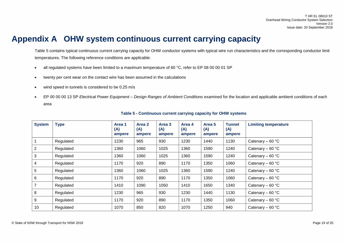
Appendix A OHW system continuous current carrying capacity Table 5 contains typical continuous current carrying capacity for OHW conductor systems with typical wire run characteristics and the corresponding conductor limit
temperatures. The following reference conditions are applicable:
• all regulated systems have been limited to a maximum temperature of 60 °C, refer to EP 08 00 00 01 SP
• twenty per cent wear on the contact wire has been assumed in the calculations
• wind speed in tunnels is considered to be 0.25 m/s
• EP 00 00 00 13 SP Electrical Power Equipment – Design Ranges of Ambient Conditions examined for the location and applicable ambient conditions of each
area
Table 5 - Continuous current carrying capacity for OHW systems
System Type Area 1 (A) ampere
Area 2 (A) ampere
Area 3 (A) ampere
Area 4 (A) ampere
Area 5 (A) ampere
Tunnel (A) ampere
Limiting temperature
1 Regulated 1230 965 930 1230 1440 1130 Catenary – 60 °C
2 Regulated 1360 1060 1025 1360 1590 1240 Catenary – 60 °C
3 Regulated 1360 1060 1025 1360 1590 1240 Catenary – 60 °C
4 Regulated 1170 920 890 1170 1350 1060 Catenary – 60 °C
5 Regulated 1360 1060 1025 1360 1590 1240 Catenary – 60 °C
6 Regulated 1170 920 890 1170 1350 1060 Catenary – 60 °C
7 Regulated 1410 1090 1050 1410 1650 1340 Catenary – 60 °C
8 Regulated 1230 965 930 1230 1440 1130 Catenary – 60 °C
9 Regulated 1170 920 890 1170 1350 1060 Catenary – 60 °C
10 Regulated 1070 850 820 1070 1250 940 Catenary – 60 °C
© State of NSW through Transport for NSW 2018 Page 19 of 20

T HR EL 08010 ST Overhead Wiring Conductor System Selection
Version 2.0 Issue date: 20 September 2018
System Type Area 1
(A) ampere
Area 2 (A) ampere
Area 3 (A) ampere
Area 4 (A) ampere
Area 5 (A) ampere
Tunnel (A) ampere
Limiting temperature
12 Regulated 2100 1650 1580 2100 2450 1910 Catenary – 60 °C
13 Regulated 2350 1850 1780 2350 2750 2130 Catenary – 60 °C
15 Regulated 1850 1450 1420 1850 2150 1640 Catenary – 60 °C
16 Regulated N/A N/A N/A N/A N/A N/A N/A
21 Fixed anchored 890 480 430 890 1155 N/A Contact – 49 °C
22 Fixed anchored 1000 650 605 1000 1200 805 Catenary – 59 °C (open route) Contact – 42 °C (tunnel)
25 Fixed anchored N/A N/A N/A N/A N/A N/A N/A
26 Fixed anchored N/A N/A N/A N/A N/A N/A N/A
27 Fixed anchored (compound) N/A N/A 1150 1715 2070 N/A Catenary – 62 °C
28 Fixed anchored 1545 1160 1105 1545 1810 1180 Catenary – 66 °C (open route) Catenary – 57 °C (tunnel)
29 Fixed anchored N/A N/A N/A N/A N/A N/A N/A
33 Fixed anchored N/A N/A N/A N/A N/A N/A N/A
34 Fixed anchored N/A N/A N/A N/A N/A N/A N/A
36 Fixed anchored N/A N/A N/A N/A N/A N/A N/A
37 Fixed anchored N/A N/A N/A N/A N/A N/A N/A
38 Fixed anchored N/A N/A N/A N/A N/A N/A N/A
39 Fixed anchored N/A N/A N/A N/A N/A N/A N/A
40 Fixed anchored N/A N/A N/A N/A N/A N/A N/A
© State of NSW through Transport for NSW 2018 Page 20 of 20


