Page 1
Overhead Wiring Maintenance Standards
T HR EL 08011 ST
Standard
Version 1.0
Issued Date: 12 March 2015
Important Warning This document is one of a set of standards developed solely and specifically for use on public transport assets which are vested in or owned, managed, controlled, commissioned or funded by the NSW Government, a NSW Government agency or a Transport Agency (as defined in the Asset Standards Authority Charter). It is not suitable for any other purpose. You must not use or adapt it or rely upon it in any way unless you are authorised in writing to do so by a relevant NSW Government agency. If this document forms part of a contract with, or is a condition of approval by a NSW Government agency, use of the document is subject to the terms of the contract or approval. This document may not be current. Current standards are available for download from the Asset Standards Authority website at www.asa.transport.nsw.gov.au.
© State of NSW through Transport for NSW
Page 2
T HR EL 08011 ST Overhead Wiring Maintenance Standards
Version 1.0 Issued Date: 12 March 2015
Standard governance
Owner: Lead Electrical Engineer, Asset Standards Authority
Authoriser: Chief Engineer Rail, Asset Standards Authority
Approver: Director, Asset Standards Authority on behalf of ASA Configuration Control Board
Document history
Version Summary of change
1.0 First issue
For queries regarding this document, please email the ASA at [email protected] or visit www.asa.transport.nsw.gov.au
© State of NSW through Transport for NSW
Page 3
T HR EL 08011 ST Overhead Wiring Maintenance Standards
Version 1.0 Issued Date: 12 March 2015
Preface The Asset Standards Authority (ASA) is an independent unit within Transport for NSW (TfNSW)
and is the network design and standards authority for defined NSW transport assets.
The ASA is responsible for developing engineering governance frameworks to support industry
delivery in the assurance of design, safety, integrity, construction, and commissioning of
transport assets for the whole asset life cycle. In order to achieve this, the ASA effectively
discharges obligations as the authority for various technical, process, and planning matters
across the asset life cycle.
The ASA collaborates with industry using stakeholder engagement activities to assist in
achieving its mission. These activities help align the ASA to broader government expectations of
making it clearer, simpler, and more attractive to do business within the NSW transport industry,
allowing the supply chain to deliver safe, efficient, and competent transport services.
The ASA develops, maintains, controls, and publishes a suite of standards and other
documentation for transport assets of TfNSW. Further, the ASA ensures that these standards
are performance based to create opportunities for innovation and improve access to a broader
competitive supply chain.
This standard supersedes RailCorp document EP 08 00 00 02 SP Overhead wiring
maintenance Standards, Version 4.0.
The changes to previous content include:
• updates to reflect organisation changes and resulting changes in responsibilities
• minor amendments and clarification to content
• conversion of the standard to ASA numbering, format and style
© State of NSW through Transport for NSW Page 3 of 30
Page 4
T HR EL 08011 ST Overhead Wiring Maintenance Standards
Version 1.0 Issued Date: 12 March 2015
Table of contents 1. Introduction ............................................................................................................................................ 5
2. Purpose ................................................................................................................................................... 5 2.1. Scope ..................................................................................................................................................................... 5 2.2. Application ............................................................................................................................................................. 6 3. Reference documents ........................................................................................................................... 6
4. Terms and definitions ........................................................................................................................... 7
5. Vegetation clearances ........................................................................................................................... 8 6. Maintenance of overhead wiring to design ......................................................................................... 8
7. Maintenance of contact wire ................................................................................................................. 9 7.1. Contact wire material ............................................................................................................................................ 9 7.2. Contact wire wear ................................................................................................................................................ 10 8. Conductor splices................................................................................................................................ 15 8.1. Catenary splices .................................................................................................................................................. 15 8.2. Contact splices .................................................................................................................................................... 15 9. Dropper arrangements ........................................................................................................................ 16
10. Section insulators ................................................................................................................................ 16
11. Insulated knuckles ............................................................................................................................... 16 12. Surge arresters .................................................................................................................................... 16
13. Wood pole support structures ........................................................................................................... 16
14. Corrective maintenance triggers........................................................................................................ 17 14.1. General ................................................................................................................................................................. 17 14.2. Conductors .......................................................................................................................................................... 18 14.3. Conductor fittings ............................................................................................................................................... 20 14.4. Switching and feeding arrangements ................................................................................................................ 21 14.5. Support and registration arrangements ............................................................................................................ 22 14.6. Anchor arrangements ......................................................................................................................................... 22 14.7. Support structures .............................................................................................................................................. 23 15. Base safety or operating limits .......................................................................................................... 23 15.1. General ................................................................................................................................................................. 24 15.2. Conductors .......................................................................................................................................................... 25 15.3. Conductor fittings ............................................................................................................................................... 27 15.4. Switching and feeding arrangements ................................................................................................................ 28 15.5. Support and registration arrangements ............................................................................................................ 28 15.6. Anchor arrangements ......................................................................................................................................... 29 15.7. Support structures .............................................................................................................................................. 29 16. Data set associated with overhead wiring maintenance ................................................................. 30
© State of NSW through Transport for NSW Page 4 of 30
Page 5
T HR EL 08011 ST Overhead Wiring Maintenance Standards
Version 1.0 Issued Date: 12 March 2015
1. Introduction Overhead wiring (OHW) is used to transmit power from traction substations to electric trains.
OHW generally consists of catenary and contact wires. The contact wire provides a
mechanically continuous path for train pantographs, and the catenary wire is used to support
the contact wire. The traction current to trains is carried by both the catenary and contact wires.
2. Purpose The purpose of this document is to set out the maintenance requirements for RailCorp's
1500 V dc OHW network.
2.1. Scope This document sets out the maintenance policies and parameters associated with the OHW
system including the following:
• vegetation management
• maintenance tolerances with respect to design
• contact wire
• catenary and contact splices
• section insulators
• insulated knuckles
• surge arresters
• wood pole support structures
Additionally, this document also includes information on the following:
• OHW maintenance tolerances and conditions that trigger corrective maintenance actions
that do not require urgent repair work. The maximum times to complete the corrective
actions are also specified.
• base safety or operating limits, which are the threshold conditions at or below which urgent
or emergency repair work to the OHW work shall be carried out
This document does not include maintenance triggers for OHW structures and their associated
bonding arrangements. OHW structures are maintained by the Civil discipline. Maintenance
triggers for structure bonding arrangements are covered in EP 12 20 00 01 SP Bonding of
Overhead Wiring Structures to Rail. However, this document requires the OHW maintainer to
report obvious visual defects to the maintainers of these assets.
© State of NSW through Transport for NSW Page 5 of 30
Page 6
T HR EL 08011 ST Overhead Wiring Maintenance Standards
Version 1.0 Issued Date: 12 March 2015
This document does not cover the requirements for the preventative maintenance of the
RailCorp 1500 V dc OHW system. This shall be done in accordance with the technical
maintenance plan (TMP).
2.2. Application This document applies to all OHW in RailCorp's 1500 V dc network that is in service.
3. Reference documents Transport for NSW standards
EP 00 00 00 13 SP Electrical power equipment – Design ranges of ambient conditions
EP 08 00 00 01 SP Overhead wiring standards for the electrification of new routes
EP 08 00 00 15 SP Overhead wiring construction and commissioning
EP 08 00 00 24 SP Contact wire
EP 10 01 00 02 SP Aerial line maintenance standards
EP 10 01 00 03 SP Aerial line base safety and operating standards
EP 10 01 00 05 SP Requirements for electric aerials crossing RailCorp infrastructure
EP 12 20 00 01 SP Bonding of overhead wiring structures to rail
EP 19 00 00 01 SP DCCB and Delta I relay setting calculation method
ESC 210 Track geometry and stability
ESC 330 Overhead wiring structures and signal gantries
T HR EL 08003 ST Level crossings – OHW requirements
T HR EL 08009 ST Designations of overhead wiring conductor systems
T HR EL 10003 ST Wood pole serviceability
T MU MD 00009 ST AEO Authorisation Requirements
T HR RS 00100 ST RSU 100 Series - Minimum Operating Standards for Rolling Stock –
General Interface Standards
TMC 212 Survey
TMC 331 Design of overhead wiring structures and signal gantries
© State of NSW through Transport for NSW Page 6 of 30
Page 7
T HR EL 08011 ST Overhead Wiring Maintenance Standards
Version 1.0 Issued Date: 12 March 2015
Transport for NSW standard drawings
CV 0131343 Standard Pantograph Profiles
EL 0002017 Contact Splice
EL 0006421 Mark 2 Cantilever Construction Pantograph Security Description Sht. 1/2
EL 0006422 Mark 2 Cantilever Construction Pantograph Security Description Sht. 2/2
EL 0011035 Catenary Feeding Loop Arrangements
EL 0026992 Contact Wire Wear Strip
EL 0034083 Catenary Terminating Clamp Details
EL 0034703 0.213 in² & 0.3 in² Contact Wire Splice & Terminal Fitting Packing Shims
EL 0040770 Contact Wire Section Area 193 mm²
EL 0189852 Contact Wire Section Area 137 mm²
EL 0251310 Contact Steady Wire Fender 6”
EL 0251311 Contact Steady Wire Fender 4”
4. Terms and definitions The following terms and definitions apply in this document:
ASA Asset Standards Authority
AEO Authorised Engineering Organisation
contact wire gradient is the ratio of the difference in height of the contact wire at two
successive supports to the length of the bay
contact wire elastic limit the elastic limit for a material is the stress beyond which permanent
deformation will occur. For the purpose of this document, the elastic limit of a contact wire is the
thickness of a contact wire at a localised wear point below which permanent deformation will
result when the wire is subjected to the maximum tension at the limits of design operating
conditions.
DCCB direct current circuit breaker
EOC electrical operating centre
heel height is the vertical distance between the contact wire at the pull off arm and the pivot
point at the heel of the pull off arm
ESR Eastern Suburbs Railway
JOS judgement of significance
© State of NSW through Transport for NSW Page 7 of 30
Page 8
T HR EL 08011 ST Overhead Wiring Maintenance Standards
Version 1.0 Issued Date: 12 March 2015
OHW overhead wiring
passing clearance is the minimum clearance required between live parts of OHW equipment
and any earthed material or rail vehicle, or between the pantograph and any earthed material,
under any permissible conditions of operation and maintenance of vehicles, track and OHW
equipment
static clearance is the minimum distance required between live parts of OHW equipment
(under any permissible conditions of maintenance when not subject to uplift from a pantograph)
and a structure or earthed part of the OHW equipment
TCM Track Control Mark
TfNSW Transport for New South Wales
TMP technical maintenance plan
5. Vegetation clearances Vegetation near OHW shall be maintained and controlled so that it is not within the following
clearance envelopes:
• 3 m from live exposed 1500 V dc equipment
• 1.5 m from overhead wiring structures and guys, and dead OHW conductors
Vegetation that has been assessed to be at risk of falling into the OHW shall also be removed,
even if it is located outside of the clearance envelopes specified above.
Allowance for regrowth between inspection and maintenance cycles shall be made when
undertaking vegetation control activities.
All vegetation control activities shall be undertaken in accordance with relevant environmental
and safety management system requirements.
6. Maintenance of overhead wiring to design New or rebuilt OHW shall be constructed and commissioned to the approved and accepted
design and within the tolerances stipulated in EP 08 00 00 01 SP Overhead Wiring Standards
For The Electrification Of New Routes.
After commissioning, the OHW shall be maintained so that deviations from the approved and
accepted design are within the tolerances set out in Table 1. These tolerances are required to
ensure pantograph security with an effective pantograph half-width of 700 mm (refer to drawing
CV 0131343 Standard Pantograph Profiles for further detail), and with the allowable vehicle
movement and track tolerances specified in T HR RS 00100 ST RSU 100 Series - Minimum
Operating Standards for Rolling Stock – General Interface Standards and ESC 210 Track
Geometry And Stability (refer to drawings EL 0006421 and EL 0006422 for further detail). © State of NSW through Transport for NSW Page 8 of 30
Page 9
T HR EL 08011 ST Overhead Wiring Maintenance Standards
Version 1.0 Issued Date: 12 March 2015
The OHW design geometry at a structure is defined with reference to the relevant track control
mark (TCM) for the structure. Within the electrical discipline, this TCM is also referred to as the
'reference nail' when installed on a mast, or 'brass bar' when installed in rock foundation. Critical
dimensions of the design track geometry relative to the TCM at the structure location are given
in the survey plaque associated with the TCM. Refer to ESC 210 Track Geometry and Stability
and TMC 212 Survey.
If the track is positioned outside of tolerances, it may be necessary to temporarily adjust the
OHW outside of the tolerances specified in Table 1 to allow for train running. Under these
circumstances, both track and OHW shall be restored to within the specified tolerances from
design as soon as practicable.
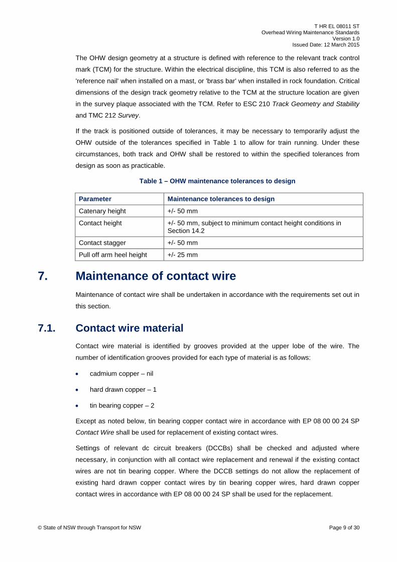
Table 1 – OHW maintenance tolerances to design
Parameter Maintenance tolerances to design
Catenary height +/- 50 mm
Contact height +/- 50 mm, subject to minimum contact height conditions in Section 14.2
Contact stagger +/- 50 mm
Pull off arm heel height +/- 25 mm
7. Maintenance of contact wire Maintenance of contact wire shall be undertaken in accordance with the requirements set out in
this section.
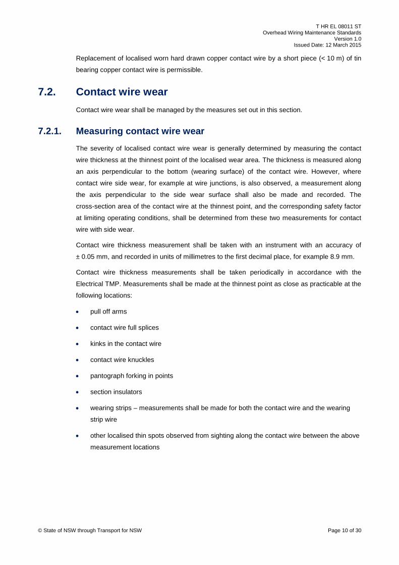
7.1. Contact wire material Contact wire material is identified by grooves provided at the upper lobe of the wire. The
number of identification grooves provided for each type of material is as follows:
• cadmium copper – nil
• hard drawn copper – 1
• tin bearing copper – 2
Except as noted below, tin bearing copper contact wire in accordance with EP 08 00 00 24 SP
Contact Wire shall be used for replacement of existing contact wires.
Settings of relevant dc circuit breakers (DCCBs) shall be checked and adjusted where
necessary, in conjunction with all contact wire replacement and renewal if the existing contact
wires are not tin bearing copper. Where the DCCB settings do not allow the replacement of
existing hard drawn copper contact wires by tin bearing copper wires, hard drawn copper
contact wires in accordance with EP 08 00 00 24 SP shall be used for the replacement.
© State of NSW through Transport for NSW Page 9 of 30
Page 10
T HR EL 08011 ST Overhead Wiring Maintenance Standards
Version 1.0 Issued Date: 12 March 2015
Replacement of localised worn hard drawn copper contact wire by a short piece (< 10 m) of tin
bearing copper contact wire is permissible.
7.2. Contact wire wear Contact wire wear shall be managed by the measures set out in this section.
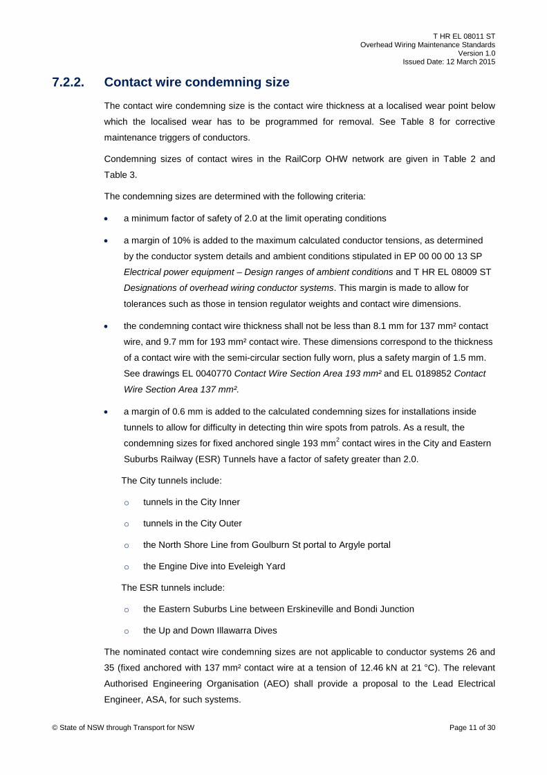
7.2.1. Measuring contact wire wear The severity of localised contact wire wear is generally determined by measuring the contact
wire thickness at the thinnest point of the localised wear area. The thickness is measured along
an axis perpendicular to the bottom (wearing surface) of the contact wire. However, where
contact wire side wear, for example at wire junctions, is also observed, a measurement along
the axis perpendicular to the side wear surface shall also be made and recorded. The
cross-section area of the contact wire at the thinnest point, and the corresponding safety factor
at limiting operating conditions, shall be determined from these two measurements for contact
wire with side wear.
Contact wire thickness measurement shall be taken with an instrument with an accuracy of
± 0.05 mm, and recorded in units of millimetres to the first decimal place, for example 8.9 mm.
Contact wire thickness measurements shall be taken periodically in accordance with the
Electrical TMP. Measurements shall be made at the thinnest point as close as practicable at the
following locations:
• pull off arms
• contact wire full splices
• kinks in the contact wire
• contact wire knuckles
• pantograph forking in points
• section insulators
• wearing strips – measurements shall be made for both the contact wire and the wearing
strip wire
• other localised thin spots observed from sighting along the contact wire between the above
measurement locations
© State of NSW through Transport for NSW Page 10 of 30
Page 11
T HR EL 08011 ST Overhead Wiring Maintenance Standards
Version 1.0 Issued Date: 12 March 2015
7.2.2. Contact wire condemning size The contact wire condemning size is the contact wire thickness at a localised wear point below
which the localised wear has to be programmed for removal. See Table 8 for corrective
maintenance triggers of conductors.
Condemning sizes of contact wires in the RailCorp OHW network are given in Table 2 and
Table 3.
The condemning sizes are determined with the following criteria:
• a minimum factor of safety of 2.0 at the limit operating conditions
• a margin of 10% is added to the maximum calculated conductor tensions, as determined
by the conductor system details and ambient conditions stipulated in EP 00 00 00 13 SP
Electrical power equipment – Design ranges of ambient conditions and T HR EL 08009 ST
Designations of overhead wiring conductor systems. This margin is made to allow for
tolerances such as those in tension regulator weights and contact wire dimensions.
• the condemning contact wire thickness shall not be less than 8.1 mm for 137 mm² contact
wire, and 9.7 mm for 193 mm² contact wire. These dimensions correspond to the thickness
of a contact wire with the semi-circular section fully worn, plus a safety margin of 1.5 mm.
See drawings EL 0040770 Contact Wire Section Area 193 mm² and EL 0189852 Contact
Wire Section Area 137 mm².
• a margin of 0.6 mm is added to the calculated condemning sizes for installations inside
tunnels to allow for difficulty in detecting thin wire spots from patrols. As a result, the
condemning sizes for fixed anchored single 193 mm2 contact wires in the City and Eastern
Suburbs Railway (ESR) Tunnels have a factor of safety greater than 2.0.
The City tunnels include:
o tunnels in the City Inner
o tunnels in the City Outer
o the North Shore Line from Goulburn St portal to Argyle portal
o the Engine Dive into Eveleigh Yard
The ESR tunnels include:
o the Eastern Suburbs Line between Erskineville and Bondi Junction
o the Up and Down Illawarra Dives
The nominated contact wire condemning sizes are not applicable to conductor systems 26 and
35 (fixed anchored with 137 mm² contact wire at a tension of 12.46 kN at 21 °C). The relevant
Authorised Engineering Organisation (AEO) shall provide a proposal to the Lead Electrical
Engineer, ASA, for such systems. © State of NSW through Transport for NSW Page 11 of 30
Page 12
T HR EL 08011 ST Overhead Wiring Maintenance Standards
Version 1.0 Issued Date: 12 March 2015
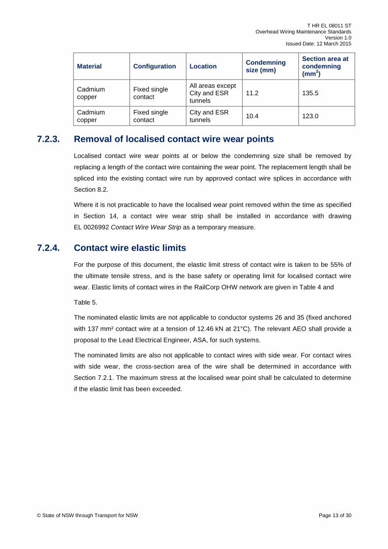
The values given in Table 2 and Table 3 are only valid for contact wires with no side wear. For
contact wires with side wear, the cross-section area shall be determined using the two
measurements as set out in Section 7.2.1. The wire shall be 'condemned' if the cross-section
area is less than or equal to the 'section area at condemning' listed in Table 2 and Table 3.
It is unlikely to have a contact wire run to be uniformly worn down to the '50% worn' section area
in accordance with EP 19 00 00 01 SP DCCB and Delta I relay setting calculation method
before part or all of the wire run has to be replaced to remove localised wear points. Contact
wire resistance is therefore not considered in the determination of condemning sizes.
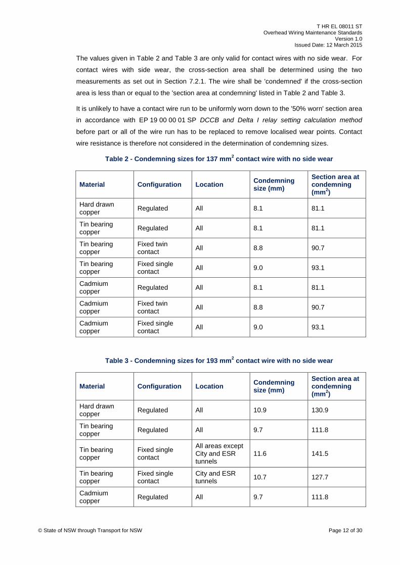
Table 2 - Condemning sizes for 137 mm2 contact wire with no side wear
Material Configuration Location Condemning size (mm)
Section area at condemning (mm2)
Hard drawn copper Regulated All 8.1 81.1
Tin bearing copper Regulated All 8.1 81.1
Tin bearing copper
Fixed twin contact All 8.8 90.7
Tin bearing copper
Fixed single contact All 9.0 93.1
Cadmium copper Regulated All 8.1 81.1
Cadmium copper
Fixed twin contact All 8.8 90.7
Cadmium copper
Fixed single contact All 9.0 93.1
Table 3 - Condemning sizes for 193 mm2 contact wire with no side wear
Material Configuration Location Condemning size (mm)
Section area at condemning (mm2)
Hard drawn copper Regulated All 10.9 130.9
Tin bearing copper Regulated All 9.7 111.8
Tin bearing copper
Fixed single contact
All areas except City and ESR tunnels
11.6 141.5
Tin bearing copper
Fixed single contact
City and ESR tunnels 10.7 127.7
Cadmium copper Regulated All 9.7 111.8
© State of NSW through Transport for NSW Page 12 of 30
Page 13
T HR EL 08011 ST Overhead Wiring Maintenance Standards
Version 1.0 Issued Date: 12 March 2015
Material Configuration Location Condemning size (mm)
Section area at condemning (mm2)
Cadmium copper
Fixed single contact
All areas except City and ESR tunnels
11.2 135.5
Cadmium copper
Fixed single contact
City and ESR tunnels 10.4 123.0
7.2.3. Removal of localised contact wire wear points Localised contact wire wear points at or below the condemning size shall be removed by
replacing a length of the contact wire containing the wear point. The replacement length shall be
spliced into the existing contact wire run by approved contact wire splices in accordance with
Section 8.2.
Where it is not practicable to have the localised wear point removed within the time as specified
in Section 14, a contact wire wear strip shall be installed in accordance with drawing
EL 0026992 Contact Wire Wear Strip as a temporary measure.
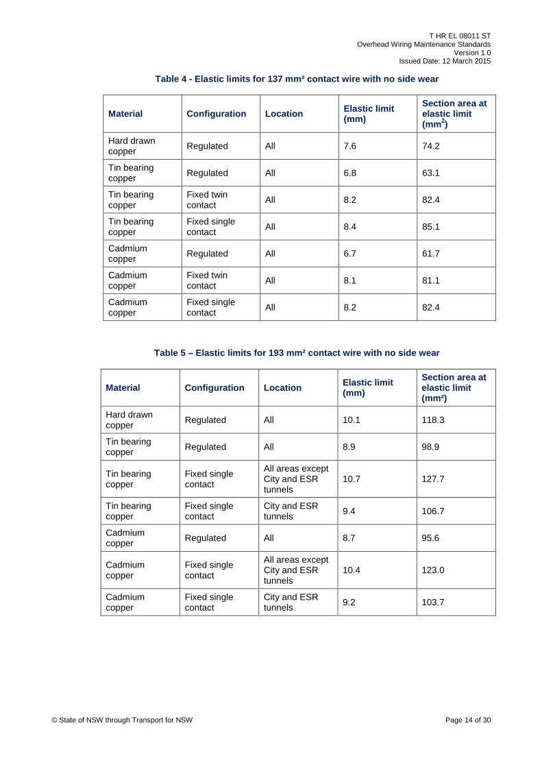
7.2.4. Contact wire elastic limits For the purpose of this document, the elastic limit stress of contact wire is taken to be 55% of
the ultimate tensile stress, and is the base safety or operating limit for localised contact wire
wear. Elastic limits of contact wires in the RailCorp OHW network are given in Table 4 and
Table 5.
The nominated elastic limits are not applicable to conductor systems 26 and 35 (fixed anchored
with 137 mm² contact wire at a tension of 12.46 kN at 21°C). The relevant AEO shall provide a
proposal to the Lead Electrical Engineer, ASA, for such systems.
The nominated limits are also not applicable to contact wires with side wear. For contact wires
with side wear, the cross-section area of the wire shall be determined in accordance with
Section 7.2.1. The maximum stress at the localised wear point shall be calculated to determine
if the elastic limit has been exceeded.
© State of NSW through Transport for NSW Page 13 of 30
Page 14
T HR EL 08011 ST Overhead Wiring Maintenance Standards
Version 1.0 Issued Date: 12 March 2015
Table 4 - Elastic limits for 137 mm² contact wire with no side wear
Material Configuration Location Elastic limit (mm)
Section area at elastic limit (mm2)
Hard drawn copper Regulated All 7.6 74.2
Tin bearing copper Regulated All 6.8 63.1
Tin bearing copper
Fixed twin contact All 8.2 82.4
Tin bearing copper
Fixed single contact All 8.4 85.1
Cadmium copper Regulated All 6.7 61.7
Cadmium copper
Fixed twin contact All 8.1 81.1
Cadmium copper
Fixed single contact All 8.2 82.4
Table 5 – Elastic limits for 193 mm² contact wire with no side wear
Material Configuration Location Elastic limit (mm)
Section area at elastic limit (mm²)
Hard drawn copper Regulated All 10.1 118.3
Tin bearing copper Regulated All 8.9 98.9
Tin bearing copper
Fixed single contact
All areas except City and ESR tunnels
10.7 127.7
Tin bearing copper
Fixed single contact
City and ESR tunnels 9.4 106.7
Cadmium copper Regulated All 8.7 95.6
Cadmium copper
Fixed single contact
All areas except City and ESR tunnels
10.4 123.0
Cadmium copper
Fixed single contact
City and ESR tunnels 9.2 103.7
© State of NSW through Transport for NSW Page 14 of 30
Page 15
T HR EL 08011 ST Overhead Wiring Maintenance Standards
Version 1.0 Issued Date: 12 March 2015
8. Conductor splices The requirements for splicing of OHW conductors are provided in this section.
8.1. Catenary splices ASA type approved helical fittings shall be used for splicing 165 mm², 270 mm² and 327 mm²
catenaries. These fittings may also be used to repair damages to these catenaries if less than
25% of the wires in the outermost layer have been severed or have other equivalent damage.
Droppers, in-span feeders, and other fittings that clamp on the catenary wire may have to be
relocated so that they are clear of the helical fitting.
Splicing of 510 mm² catenary shall be done by terminating the conductors, installing a suitable
link between the terminating clamps and connecting the 'tails' of the catenary conductors
together, in a manner similar to that shown in drawing EL 0011035 Catenary Feeding Loop
Arrangement. The termination clamp shall be fitting number 281/9 (drawing EL 0034083
Catenary Terminating Clamp Details).
8.2. Contact splices 'In running' contact wires shall be spliced by fitting number 462/8 (drawing EL 0002017 Contact
Splice) with suitable wedges and shims in accordance with drawing EL 0002017.
For worn contact wires, copper shims are installed in the mouth of the splice fitting to ensure
that the running edge of the contact wire is flush with the underside of the splice. Table 6 gives
a guide to the number of shims to be used. The contact wire splice is not suitable for contact
wires with a thickness less than 9.9 mm. Hence contact wire replacement may have to be
extended beyond the localised wear point.
As contact wire splices are 'hard spots' for pantograph running, no more than three contact
splices shall be installed between two adjacent support structures.
Table 6 – Guide to shim installation requirements for contact wire full splice
Contact wire thickness (mm) Number of long shims (fitting 462/6; drawing EL 0034703)
Number of short shims (fitting 462/16; drawing EL 0034703)
16.4 – 15.5 (new 193 mm²) 0 0
15.4 – 14.6 1 0
14.5 – 13.5 (new 137 mm²) 2 0
13.4 – 12.5 1 1
12.4 – 11.5 2 1
11.4 – 10.5 1 2
10.4 – 9.9 2 2 © State of NSW through Transport for NSW Page 15 of 30
Page 16
T HR EL 08011 ST Overhead Wiring Maintenance Standards
Version 1.0 Issued Date: 12 March 2015
9. Dropper arrangements Where existing droppers have to be replaced, they shall be replaced by insulated droppers in
accordance with EP 08 00 00 01 SP.
10. Section insulators Where existing section insulators have to be replaced, they shall be replaced by 'Type 6' section
insulators in accordance with EP 08 00 00 01 SP.
11. Insulated knuckles There is currently no suitable replacement for insulated knuckles with timber beams. Existing
OHW with such insulated knuckles may need to be reconfigured when the knuckles are no
longer suitable to remain in service. The maintainer shall plan the required modifications with
sufficient time allowed for design and construction.
12. Surge arresters Some previous standard arrangements for OHW required surge arresters to be installed on the
overhead wiring approximately mid-way between substations. This practice is no longer
required. Existing 'mid-way' surge arresters shall be removed at the next hands-on inspection or
when the overhead wiring in the area is modified.
Surge arresters are still required at cable to aerial feeder junction locations. See
EP 08 00 00 01 SP for further information.
13. Wood pole support structures Standard T HR EL 10003 ST Wood pole serviceability details serviceability criteria of wood
poles.
Where an existing OHW wood pole support structure has to be replaced, it shall be replaced by
one or more structure(s) satisfying the requirements of ESC 330 Overhead wiring structures and
signal gantries and TMC 331 Design of overhead wiring structures and signal gantries.
© State of NSW through Transport for NSW Page 16 of 30
Page 17
T HR EL 08011 ST Overhead Wiring Maintenance Standards
Version 1.0 Issued Date: 12 March 2015
14. Corrective maintenance triggers Common conditions that trigger corrective maintenance actions are listed in the subsections
below. Care shall be exercised by the maintainer to ensure that base safety and operational
limits (see Section 15) are not breached before the completion of corrective actions.
The values listed under 'time to complete corrective action' are maximum allowable times.
Depending on the nature and extent of the defect, shorter time periods may need to be applied
for individual cases to ensure that the risks to personnel safety and train operations caused by
failure of the identified defect(s) are as low as reasonably practicable. Longer periods to
complete corrective action may be approved by the responsible AEO under a judgement of
significance (JOS) process for OHW on a case by case basis. Refer to T MU MD 00009 ST
AEO Authorisation Requirements for further information.
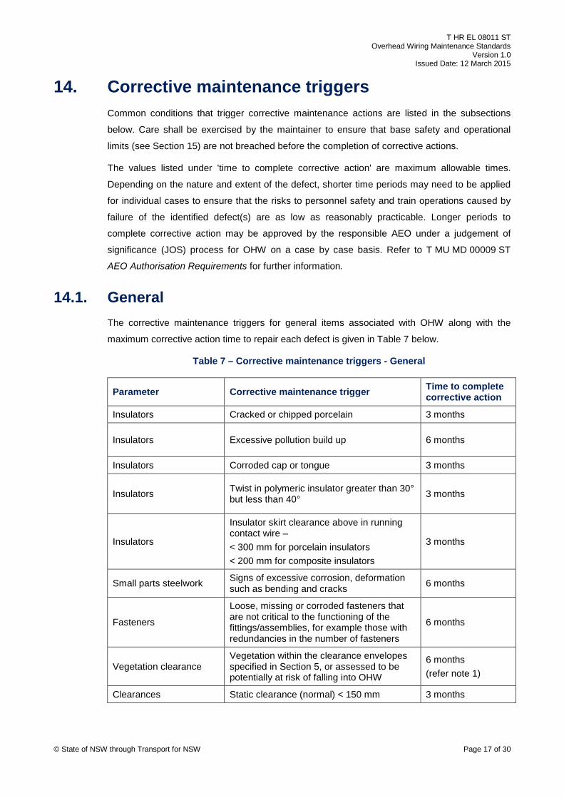
14.1. General The corrective maintenance triggers for general items associated with OHW along with the
maximum corrective action time to repair each defect is given in Table 7 below.
Table 7 – Corrective maintenance triggers - General
Parameter Corrective maintenance trigger Time to complete corrective action
Insulators Cracked or chipped porcelain 3 months
Insulators Excessive pollution build up 6 months
Insulators Corroded cap or tongue 3 months
Insulators Twist in polymeric insulator greater than 30° but less than 40° 3 months
Insulators
Insulator skirt clearance above in running contact wire – < 300 mm for porcelain insulators < 200 mm for composite insulators
3 months
Small parts steelwork Signs of excessive corrosion, deformation such as bending and cracks 6 months
Fasteners
Loose, missing or corroded fasteners that are not critical to the functioning of the fittings/assemblies, for example those with redundancies in the number of fasteners
6 months
Vegetation clearance Vegetation within the clearance envelopes specified in Section 5, or assessed to be potentially at risk of falling into OHW
6 months (refer note 1)
Clearances Static clearance (normal) < 150 mm 3 months
© State of NSW through Transport for NSW Page 17 of 30
Page 18
T HR EL 08011 ST Overhead Wiring Maintenance Standards
Version 1.0 Issued Date: 12 March 2015
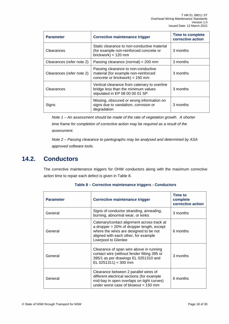
Parameter Corrective maintenance trigger Time to complete corrective action
Clearances Static clearance to non-conductive material (for example non-reinforced concrete or brickwork) < 120 mm
3 months
Clearances (refer note 2) Passing clearance (normal) < 200 mm 3 months
Clearances (refer note 2) Passing clearance to non-conductive material (for example non-reinforced concrete or brickwork) < 150 mm
3 months
Clearances Vertical clearance from catenary to overline bridge less than the minimum values stipulated in EP 08 00 00 01 SP
3 months
Signs Missing, obscured or wrong information on signs due to vandalism, corrosion or degradation
3 months
Note 1 – An assessment should be made of the rate of vegetation growth. A shorter
time frame for completion of corrective action may be required as a result of the
assessment.
Note 2 – Passing clearance to pantographs may be analysed and determined by ASA
approved software tools.
14.2. Conductors The corrective maintenance triggers for OHW conductors along with the maximum corrective
action time to repair each defect is given in Table 8.
Table 8 – Corrective maintenance triggers - Conductors
Parameter Corrective maintenance trigger Time to complete corrective action
General Signs of conductor stranding, annealing, burning, abnormal wear, or kinks 3 months
General
Catenary/contact alignment across track at a dropper > 20% of dropper length, except where the wires are designed to be not aligned with each other, for example Liverpool to Glenlee
6 months
General
Clearance of span wire above in running contact wire (without fender fitting 395 or 395/1 as per drawings EL 0251310 and EL 0251311) < 300 mm
3 months
General
Clearance between 2 parallel wires of different electrical sections (for example mid-bay in open overlaps on tight curves) under worst case of blowout < 150 mm
6 months
© State of NSW through Transport for NSW Page 18 of 30
Page 19
T HR EL 08011 ST Overhead Wiring Maintenance Standards
Version 1.0 Issued Date: 12 March 2015
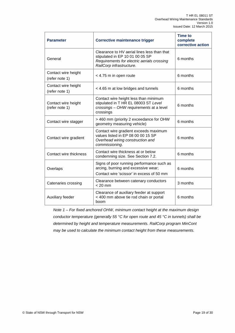
Parameter Corrective maintenance trigger Time to complete corrective action
General
Clearance to HV aerial lines less than that stipulated in EP 10 01 00 05 SP Requirements for electric aerials crossing RailCorp infrastructure.
6 months
Contact wire height (refer note 1)
< 4.75 m in open route 6 months
Contact wire height (refer note 1)
< 4.65 m at low bridges and tunnels 6 months
Contact wire height (refer note 1)
Contact wire height less than minimum stipulated in T HR EL 08003 ST Level crossings – OHW requirements at a level crossings
6 months
Contact wire stagger > 460 mm (priority 2 exceedance for OHW geometry measuring vehicle) 6 months
Contact wire gradient
Contact wire gradient exceeds maximum values listed in EP 08 00 00 15 SP Overhead wiring construction and commissioning.
6 months
Contact wire thickness Contact wire thickness at or below condemning size. See Section 7.2. 6 months
Overlaps Signs of poor running performance such as arcing, burning and excessive wear; Contact wire 'scissor' in excess of 50 mm
6 months
Catenaries crossing Clearance between catenary conductors < 20 mm 3 months
Auxiliary feeder Clearance of auxiliary feeder at support < 400 mm above tie rod chain or portal boom
6 months
Note 1 – For fixed anchored OHW, minimum contact height at the maximum design
conductor temperature (generally 55 °C for open route and 45 °C in tunnels) shall be
determined by height and temperature measurements. RailCorp program MinCont
may be used to calculate the minimum contact height from these measurements.
© State of NSW through Transport for NSW Page 19 of 30
Page 20
T HR EL 08011 ST Overhead Wiring Maintenance Standards
Version 1.0 Issued Date: 12 March 2015
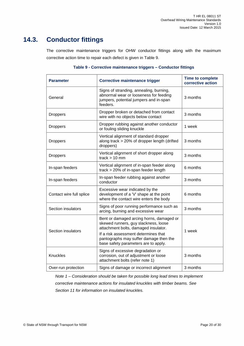
14.3. Conductor fittings The corrective maintenance triggers for OHW conductor fittings along with the maximum
corrective action time to repair each defect is given in Table 9.
Table 9 - Corrective maintenance triggers – Conductor fittings
Parameter Corrective maintenance trigger Time to complete corrective action
General
Signs of stranding, annealing, burning, abnormal wear or looseness for feeding jumpers, potential jumpers and in-span feeders.
3 months
Droppers Dropper broken or detached from contact wire with no objects below contact 3 months
Droppers Dropper rubbing against another conductor or fouling sliding knuckle 1 week
Droppers Vertical alignment of standard dropper along track > 20% of dropper length (drifted droppers)
3 months
Droppers Vertical alignment of short dropper along track > 10 mm 3 months
In-span feeders Vertical alignment of in-span feeder along track > 20% of in-span feeder length 6 months
In-span feeders In-span feeder rubbing against another conductor 3 months
Contact wire full splice Excessive wear indicated by the development of a 'V' shape at the point where the contact wire enters the body
6 months
Section insulators Signs of poor running performance such as arcing, burning and excessive wear 3 months
Section insulators
Bent or damaged arcing horns, damaged or skewed runners, guy slackness, loose attachment bolts, damaged insulator. If a risk assessment determines that pantographs may suffer damage then the base safety parameters are to apply.
1 week
Knuckles Signs of excessive degradation or corrosion, out of adjustment or loose attachment bolts (refer note 1)
3 months
Over-run protection Signs of damage or incorrect alignment 3 months
Note 1 – Consideration should be taken for possible long lead times to implement
corrective maintenance actions for insulated knuckles with timber beams. See
Section 11 for information on insulated knuckles.
© State of NSW through Transport for NSW Page 20 of 30
Page 21
T HR EL 08011 ST Overhead Wiring Maintenance Standards
Version 1.0 Issued Date: 12 March 2015
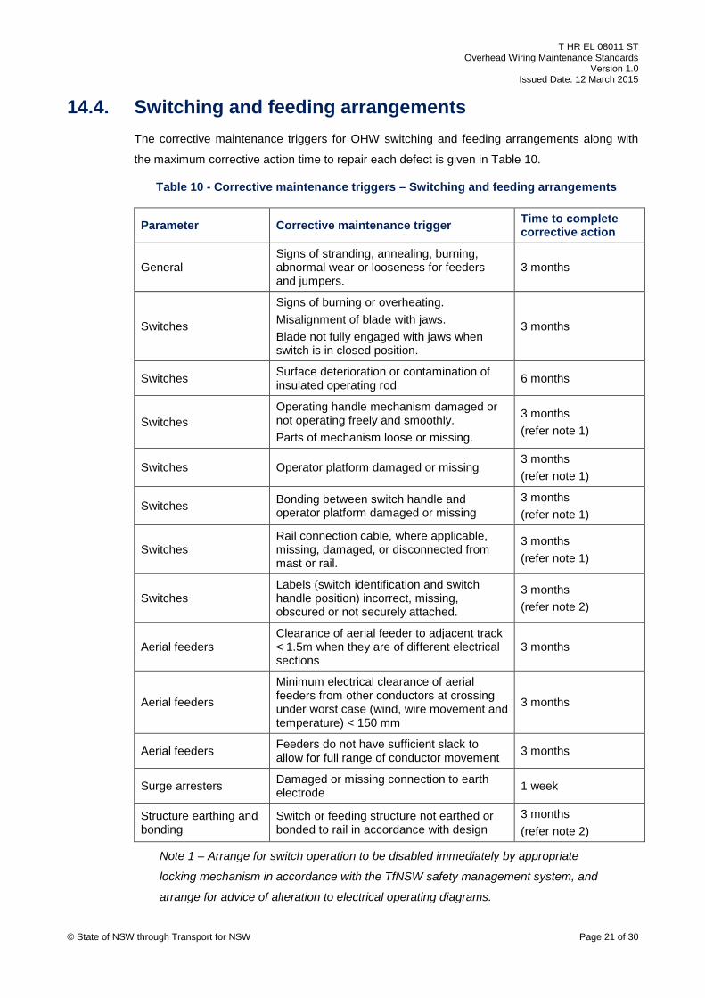
14.4. Switching and feeding arrangements The corrective maintenance triggers for OHW switching and feeding arrangements along with
the maximum corrective action time to repair each defect is given in Table 10.
Table 10 - Corrective maintenance triggers – Switching and feeding arrangements
Parameter Corrective maintenance trigger Time to complete corrective action
General Signs of stranding, annealing, burning, abnormal wear or looseness for feeders and jumpers.
3 months
Switches
Signs of burning or overheating. Misalignment of blade with jaws. Blade not fully engaged with jaws when switch is in closed position.
3 months
Switches Surface deterioration or contamination of insulated operating rod 6 months
Switches Operating handle mechanism damaged or not operating freely and smoothly. Parts of mechanism loose or missing.
3 months (refer note 1)
Switches Operator platform damaged or missing 3 months (refer note 1)
Switches Bonding between switch handle and operator platform damaged or missing
3 months (refer note 1)
Switches Rail connection cable, where applicable, missing, damaged, or disconnected from mast or rail.
3 months (refer note 1)
Switches Labels (switch identification and switch handle position) incorrect, missing, obscured or not securely attached.
3 months (refer note 2)
Aerial feeders Clearance of aerial feeder to adjacent track < 1.5m when they are of different electrical sections
3 months
Aerial feeders
Minimum electrical clearance of aerial feeders from other conductors at crossing under worst case (wind, wire movement and temperature) < 150 mm
3 months
Aerial feeders Feeders do not have sufficient slack to allow for full range of conductor movement 3 months
Surge arresters Damaged or missing connection to earth electrode 1 week
Structure earthing and bonding
Switch or feeding structure not earthed or bonded to rail in accordance with design
3 months (refer note 2)
Note 1 – Arrange for switch operation to be disabled immediately by appropriate
locking mechanism in accordance with the TfNSW safety management system, and
arrange for advice of alteration to electrical operating diagrams. © State of NSW through Transport for NSW Page 21 of 30
Page 22
T HR EL 08011 ST Overhead Wiring Maintenance Standards
Version 1.0 Issued Date: 12 March 2015
Note 2 – Install temporary signs or warning labels immediately.
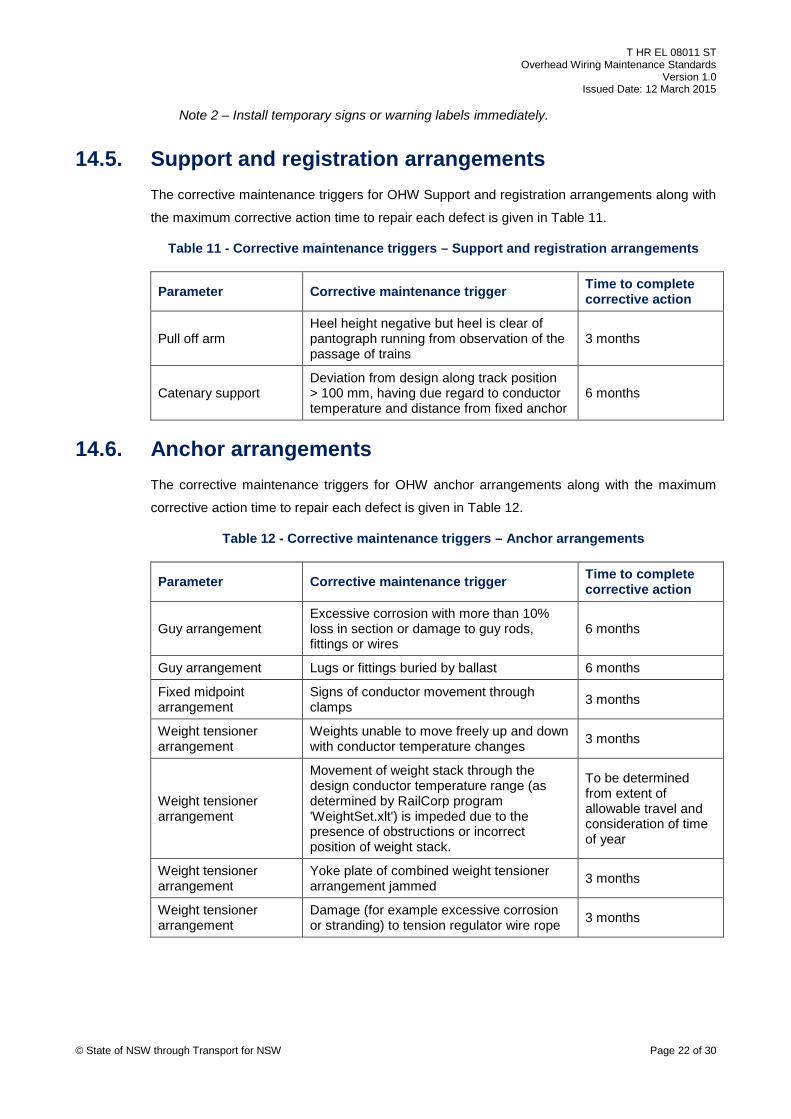
14.5. Support and registration arrangements The corrective maintenance triggers for OHW Support and registration arrangements along with
the maximum corrective action time to repair each defect is given in Table 11.
Table 11 - Corrective maintenance triggers – Support and registration arrangements
Parameter Corrective maintenance trigger Time to complete corrective action
Pull off arm Heel height negative but heel is clear of pantograph running from observation of the passage of trains
3 months
Catenary support Deviation from design along track position > 100 mm, having due regard to conductor temperature and distance from fixed anchor
6 months
14.6. Anchor arrangements The corrective maintenance triggers for OHW anchor arrangements along with the maximum
corrective action time to repair each defect is given in Table 12.
Table 12 - Corrective maintenance triggers – Anchor arrangements
Parameter Corrective maintenance trigger Time to complete corrective action
Guy arrangement Excessive corrosion with more than 10% loss in section or damage to guy rods, fittings or wires
6 months
Guy arrangement Lugs or fittings buried by ballast 6 months
Fixed midpoint arrangement
Signs of conductor movement through clamps 3 months
Weight tensioner arrangement
Weights unable to move freely up and down with conductor temperature changes 3 months
Weight tensioner arrangement
Movement of weight stack through the design conductor temperature range (as determined by RailCorp program 'WeightSet.xlt') is impeded due to the presence of obstructions or incorrect position of weight stack.
To be determined from extent of allowable travel and consideration of time of year
Weight tensioner arrangement
Yoke plate of combined weight tensioner arrangement jammed 3 months
Weight tensioner arrangement
Damage (for example excessive corrosion or stranding) to tension regulator wire rope 3 months
© State of NSW through Transport for NSW Page 22 of 30
Page 23
T HR EL 08011 ST Overhead Wiring Maintenance Standards
Version 1.0 Issued Date: 12 March 2015
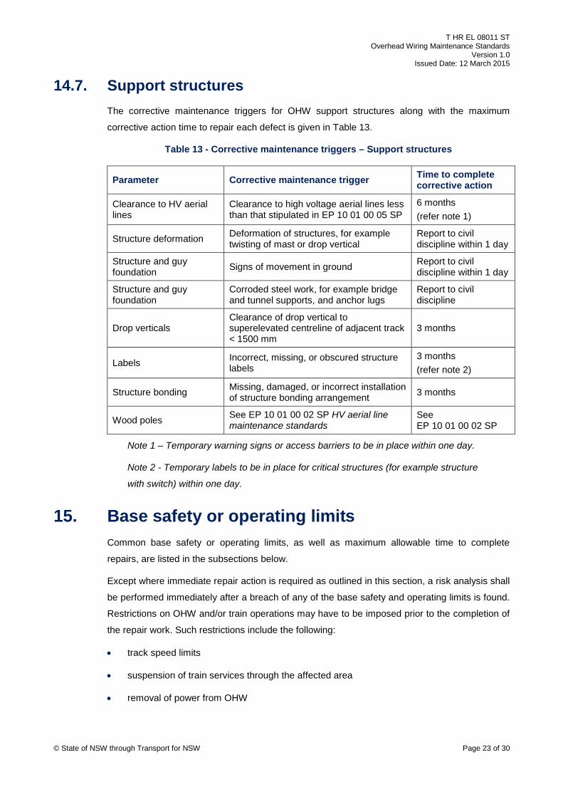
14.7. Support structures The corrective maintenance triggers for OHW support structures along with the maximum
corrective action time to repair each defect is given in Table 13.
Table 13 - Corrective maintenance triggers – Support structures
Parameter Corrective maintenance trigger Time to complete corrective action
Clearance to HV aerial lines
Clearance to high voltage aerial lines less than that stipulated in EP 10 01 00 05 SP
6 months (refer note 1)
Structure deformation Deformation of structures, for example twisting of mast or drop vertical
Report to civil discipline within 1 day
Structure and guy foundation Signs of movement in ground Report to civil
discipline within 1 day
Structure and guy foundation
Corroded steel work, for example bridge and tunnel supports, and anchor lugs
Report to civil discipline
Drop verticals Clearance of drop vertical to superelevated centreline of adjacent track < 1500 mm
3 months
Labels Incorrect, missing, or obscured structure labels
3 months (refer note 2)
Structure bonding Missing, damaged, or incorrect installation of structure bonding arrangement 3 months
Wood poles See EP 10 01 00 02 SP HV aerial line maintenance standards
See EP 10 01 00 02 SP
Note 1 – Temporary warning signs or access barriers to be in place within one day.
Note 2 - Temporary labels to be in place for critical structures (for example structure
with switch) within one day.
15. Base safety or operating limits Common base safety or operating limits, as well as maximum allowable time to complete
repairs, are listed in the subsections below.
Except where immediate repair action is required as outlined in this section, a risk analysis shall
be performed immediately after a breach of any of the base safety and operating limits is found.
Restrictions on OHW and/or train operations may have to be imposed prior to the completion of
the repair work. Such restrictions include the following:
• track speed limits
• suspension of train services through the affected area
• removal of power from OHW
© State of NSW through Transport for NSW Page 23 of 30
Page 24
T HR EL 08011 ST Overhead Wiring Maintenance Standards
Version 1.0 Issued Date: 12 March 2015
The values listed for 'time to complete corrective action' are maximum allowable times.
Immediate action shall be initiated if there is a risk of imminent failure. The maximum allowable
times may be varied as a result of a risk analysis performed by the responsible AEO under a
judgement of significance (JOS) process for OHW, with consideration given to the applicable
site specific operating environment and the implementation of temporary measures.
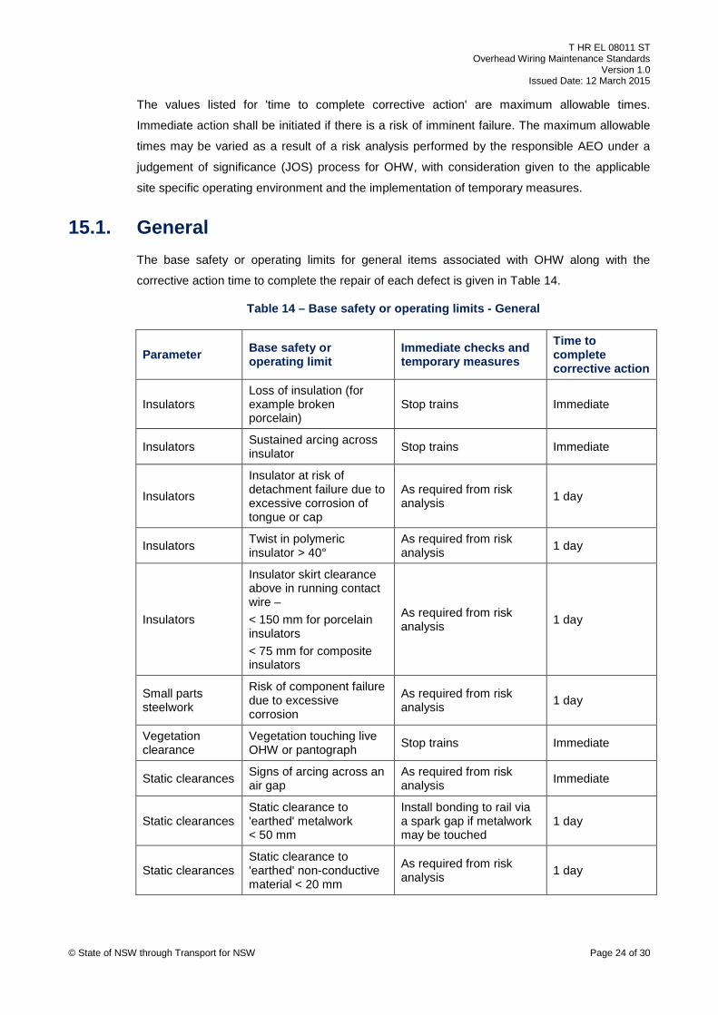
15.1. General The base safety or operating limits for general items associated with OHW along with the
corrective action time to complete the repair of each defect is given in Table 14.
Table 14 – Base safety or operating limits - General
Parameter Base safety or operating limit
Immediate checks and temporary measures
Time to complete corrective action
Insulators Loss of insulation (for example broken porcelain)
Stop trains Immediate
Insulators Sustained arcing across insulator Stop trains Immediate
Insulators
Insulator at risk of detachment failure due to excessive corrosion of tongue or cap
As required from risk analysis 1 day
Insulators Twist in polymeric insulator > 40°
As required from risk analysis 1 day
Insulators
Insulator skirt clearance above in running contact wire – < 150 mm for porcelain insulators < 75 mm for composite insulators
As required from risk analysis 1 day
Small parts steelwork
Risk of component failure due to excessive corrosion
As required from risk analysis 1 day
Vegetation clearance
Vegetation touching live OHW or pantograph Stop trains Immediate
Static clearances Signs of arcing across an air gap
As required from risk analysis Immediate
Static clearances Static clearance to 'earthed' metalwork < 50 mm
Install bonding to rail via a spark gap if metalwork may be touched
1 day
Static clearances Static clearance to 'earthed' non-conductive material < 20 mm
As required from risk analysis 1 day
te of NSW through Transport for NSW Page 24 of 30
© Sta
Page 25
T HR EL 08011 ST Overhead Wiring Maintenance Standards
Version 1.0 Issued Date: 12 March 2015
Parameter Base safety or operating limit
Immediate checks and temporary measures
Time to complete corrective action
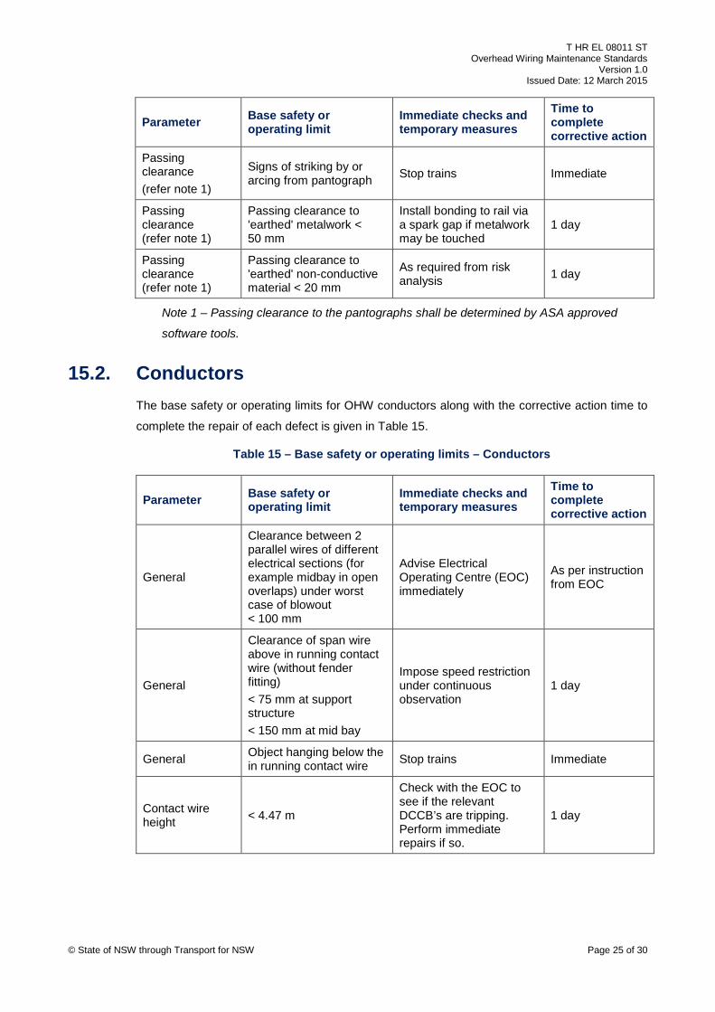
Passing clearance (refer note 1)
Signs of striking by or arcing from pantograph Stop trains Immediate
Passing clearance (refer note 1)
Passing clearance to 'earthed' metalwork < 50 mm
Install bonding to rail via a spark gap if metalwork may be touched
1 day
Passing clearance (refer note 1)
Passing clearance to 'earthed' non-conductive material < 20 mm
As required from risk analysis 1 day
Note 1 – Passing clearance to the pantographs shall be determined by ASA approved
software tools.
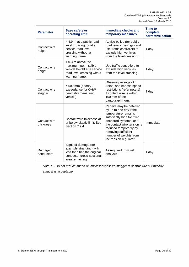
15.2. Conductors The base safety or operating limits for OHW conductors along with the corrective action time to
complete the repair of each defect is given in Table 15.
Table 15 – Base safety or operating limits – Conductors
Parameter Base safety or operating limit
Immediate checks and temporary measures
Time to complete corrective action
General
Clearance between 2 parallel wires of different electrical sections (for example midbay in open overlaps) under worst case of blowout < 100 mm
Advise Electrical Operating Centre (EOC) immediately
As per instruction from EOC
General
Clearance of span wire above in running contact wire (without fender fitting) < 75 mm at support structure < 150 mm at mid bay
Impose speed restriction under continuous observation
1 day
General Object hanging below the in running contact wire Stop trains Immediate
Contact wire height < 4.47 m
Check with the EOC to see if the relevant DCCB’s are tripping. Perform immediate repairs if so.
1 day
© State of NSW through Transport for NSW Page 25 of 30
Page 26
T HR EL 08011 ST Overhead Wiring Maintenance Standards
Version 1.0 Issued Date: 12 March 2015
Parameter Base safety or operating limit
Immediate checks and temporary measures
Time to complete corrective action
Contact wire height
< 4.9 m at a public road level crossing, or at a service road level crossing without a warning frame
Advise police (for public road level crossings) and use traffic controllers to exclude high vehicles from the level crossing.
1 day
Contact wire height
< 0.3 m above the maximum permissible vehicle height at a service road level crossing with a warning frame.
Use traffic controllers to exclude high vehicles from the level crossing.
1 day
Contact wire stagger
> 500 mm (priority 1 exceedance for OHW geometry measuring vehicle)
Observe passage of trains, and impose speed restrictions (refer note 1) if contact wire is within 100 mm of the pantograph horn.
1 day
Contact wire thickness
Contact wire thickness at or below elastic limit. See Section 7.2.4
Repairs may be deferred by up to one day if the temperature remains sufficiently high for fixed anchored systems, or if the contact wire tension is reduced temporarily by removing sufficient number of weights from the tension regulator.
Immediate
Damaged conductors
Signs of damage (for example stranding) with less than half the original conductor cross-sectional area remaining.
As required from risk analysis 1 day
Note 1 – Do not reduce speed on curve if excessive stagger is at structure but midbay
stagger is acceptable.
© State of NSW through Transport for NSW Page 26 of 30
Page 27
T HR EL 08011 ST Overhead Wiring Maintenance Standards
Version 1.0 Issued Date: 12 March 2015
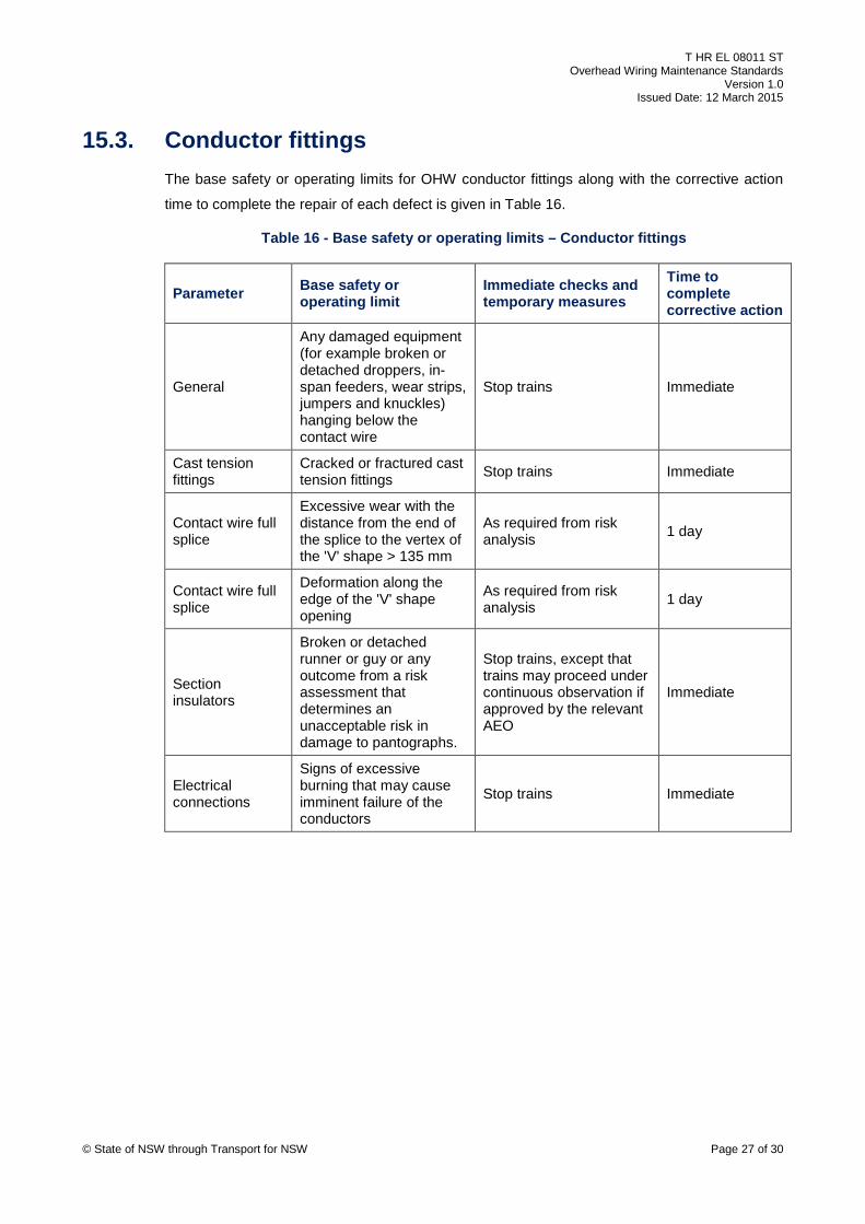
15.3. Conductor fittings The base safety or operating limits for OHW conductor fittings along with the corrective action
time to complete the repair of each defect is given in Table 16.
Table 16 - Base safety or operating limits – Conductor fittings
Parameter Base safety or operating limit
Immediate checks and temporary measures
Time to complete corrective action
General
Any damaged equipment (for example broken or detached droppers, in-span feeders, wear strips, jumpers and knuckles) hanging below the contact wire
Stop trains Immediate
Cast tension fittings
Cracked or fractured cast tension fittings Stop trains Immediate
Contact wire full splice
Excessive wear with the distance from the end of the splice to the vertex of the 'V' shape > 135 mm
As required from risk analysis 1 day
Contact wire full splice
Deformation along the edge of the 'V' shape opening
As required from risk analysis 1 day
Section insulators
Broken or detached runner or guy or any outcome from a risk assessment that determines an unacceptable risk in damage to pantographs.
Stop trains, except that trains may proceed under continuous observation if approved by the relevant AEO
Immediate
Electrical connections
Signs of excessive burning that may cause imminent failure of the conductors
Stop trains Immediate
© State of NSW through Transport for NSW Page 27 of 30
Page 28
T HR EL 08011 ST Overhead Wiring Maintenance Standards
Version 1.0 Issued Date: 12 March 2015
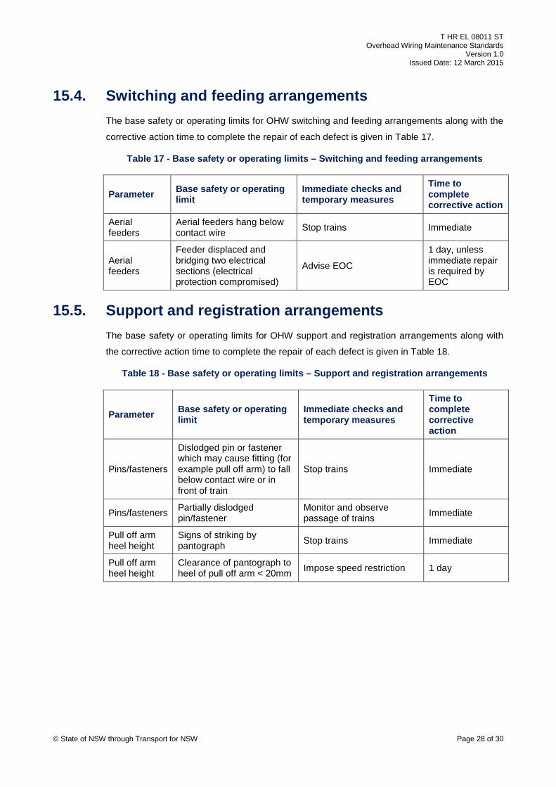
15.4. Switching and feeding arrangements The base safety or operating limits for OHW switching and feeding arrangements along with the
corrective action time to complete the repair of each defect is given in Table 17.
Table 17 - Base safety or operating limits – Switching and feeding arrangements
Parameter Base safety or operating limit
Immediate checks and temporary measures
Time to complete corrective action
Aerial feeders
Aerial feeders hang below contact wire Stop trains Immediate
Aerial feeders
Feeder displaced and bridging two electrical sections (electrical protection compromised)
Advise EOC
1 day, unless immediate repair is required by EOC
15.5. Support and registration arrangements The base safety or operating limits for OHW support and registration arrangements along with
the corrective action time to complete the repair of each defect is given in Table 18.
Table 18 - Base safety or operating limits – Support and registration arrangements
Parameter Base safety or operating limit
Immediate checks and temporary measures
Time to complete corrective action
Pins/fasteners
Dislodged pin or fastener which may cause fitting (for example pull off arm) to fall below contact wire or in front of train
Stop trains Immediate
Pins/fasteners Partially dislodged pin/fastener
Monitor and observe passage of trains Immediate
Pull off arm heel height
Signs of striking by pantograph Stop trains Immediate
Pull off arm heel height
Clearance of pantograph to heel of pull off arm < 20mm Impose speed restriction 1 day
© State of NSW through Transport for NSW Page 28 of 30
Page 29
T HR EL 08011 ST Overhead Wiring Maintenance Standards
Version 1.0 Issued Date: 12 March 2015
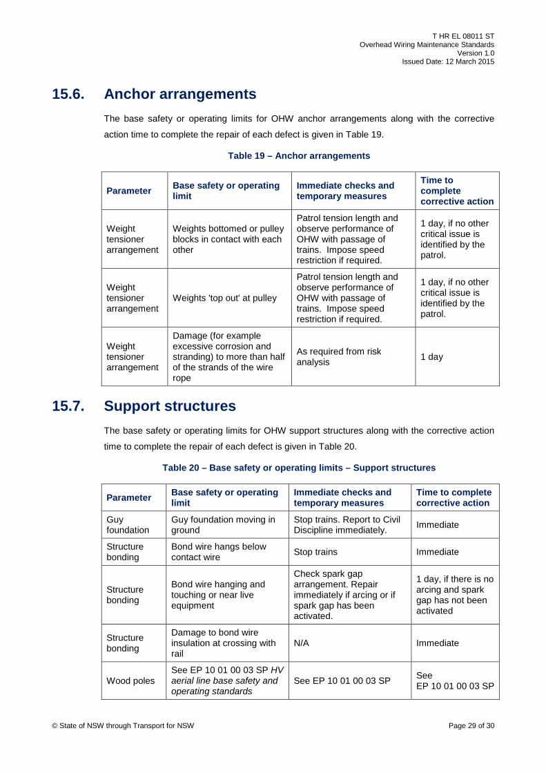
15.6. Anchor arrangements The base safety or operating limits for OHW anchor arrangements along with the corrective
action time to complete the repair of each defect is given in Table 19.
Table 19 – Anchor arrangements
Parameter Base safety or operating limit
Immediate checks and temporary measures
Time to complete corrective action
Weight tensioner arrangement
Weights bottomed or pulley blocks in contact with each other
Patrol tension length and observe performance of OHW with passage of trains. Impose speed restriction if required.
1 day, if no other critical issue is identified by the patrol.
Weight tensioner arrangement
Weights 'top out' at pulley
Patrol tension length and observe performance of OHW with passage of trains. Impose speed restriction if required.
1 day, if no other critical issue is identified by the patrol.
Weight tensioner arrangement
Damage (for example excessive corrosion and stranding) to more than half of the strands of the wire rope
As required from risk analysis 1 day
15.7. Support structures The base safety or operating limits for OHW support structures along with the corrective action
time to complete the repair of each defect is given in Table 20.
Table 20 – Base safety or operating limits – Support structures
Parameter Base safety or operating limit
Immediate checks and temporary measures
Time to complete corrective action
Guy foundation
Guy foundation moving in ground
Stop trains. Report to Civil Discipline immediately. Immediate
Structure bonding
Bond wire hangs below contact wire Stop trains Immediate
Structure bonding
Bond wire hanging and touching or near live equipment
Check spark gap arrangement. Repair immediately if arcing or if spark gap has been activated.
1 day, if there is no arcing and spark gap has not been activated
Structure bonding
Damage to bond wire insulation at crossing with rail
N/A Immediate
Wood poles See EP 10 01 00 03 SP HV aerial line base safety and operating standards
See EP 10 01 00 03 SP See EP 10 01 00 03 SP
© State of NSW through Transport for NSW Page 29 of 30
Page 30
T HR EL 08011 ST Overhead Wiring Maintenance Standards
Version 1.0 Issued Date: 12 March 2015
16. Data set associated with overhead wiring maintenance The maintainer shall ensure that the data set associated with OHW, as stipulated in
EP 08 00 00 01 SP is up to date and in accordance with the as-built configuration.
Any deviations from standard operating conditions, such as a maximum conductor temperature
higher than 60 °C for regulated OHW with 'short' tension lengths, shall be clearly indicated on
the relevant layout drawing(s).
Where urgent repairs are carried out, the maintainer shall ensure that the data set associated
with the OHW is updated in accordance with the as-built configuration as soon as practicable,
and not less than one month after the completion of the repairs.
© State of NSW through Transport for NSW Page 30 of 30