TO APPEAR IN IEEE TRANS. ON VEHICULAR TECHNOLOGY, JUNE 1998 1 Overlapping M-ary Frequency Shift Keying Spread-Spectrum Multiple-Access Systems Using Random Signature Sequences 1, 2 Lie-Liang Yang, Member, IEEE, and Lajos Hanzo, Senior Member, IEEE Dept. of Electronics and Computer Science, University of Southampton, SO17 1BJ, UK. Tel: +44-703-593 125, Fax: +44-703-594 508 Email: [email protected]and [email protected]http://www-mobile.ecs.soton.ac.uk Abstract In this paper, a multiple-access spread-spectrum communication system using binary frequency shift keying (BFSK) or M -ary frequency shift keying (MFSK), and noncoherent demodulation is considered. In contrast to previous work typically assuming that the FSK tones are non-overlapping after direct-sequence (DS) spreading, here we consider a spread spectrum multiple access (SSMA) system under the assumption that the DS spread signals of different FSK tones are only orthogonal over the information symbol duration. Consequently, the frequency band of a spread FSK tone may be fully or partially overlapping with the other spread signals. An estimate of the variance of the multiple-access interference is obtained by assuming that the phase angles and time delays of the received signals are mutually independent random variables, provided that random signature sequences are employed for spreading. On the basis of the above assumptions, the bit error rate (BER) of our direct-sequence, spread-spectrum multiple-access (DS-SSMA) and that of our hybrid direct-sequence, slow frequency-hopping spread-spectrum multiple access (DS-SFH SSMA) systems using FSK modulation is analyzed, when the channel impairments are constituted by a combination of additive white Gaussian noise (AWGN) and multiple-access interference. From our analysis and the numerical results, we concluded that, for a given system bandwidth and for a certain value of M , the system’s BER performance can be optimized by controlling the amount of overlapping, and that the systems with optimized overlapping outperformed the systems using no overlapping. Keywords M -ary frequency shift keying, spread-spectrum multiple-access, direct-sequence (DS), slow frequency-hopping (SFH), hybrid DS/SFH. 1 The paper was accepted for publication in IEEE Trans. on Vehicular Technology, 1998. The work was partly supported by the Sino-British Fellowship Trust of Royal Society. 2 copyright 1999 IEEE. Personal use of this material is permitted. However, permission to reprint/republish this material for advertising or promotional purposes or for creating new collective works for resale or redistribution to servers or lists, or to refuse any copyrighted component of this work in other works must be obtained from the IEEE.
Transcript
TO APPEAR IN IEEE TRANS. ON VEHICULAR TECHNOLOGY, JUNE 1998 1
Overlapping M-ary Frequency Shift Keying
Spread-Spectrum Multiple-Access Systems
Using Random Signature Sequences1, 2
Lie-Liang Yang, Member, IEEE, and Lajos Hanzo, Senior Member, IEEE
In this paper, a multiple-access spread-spectrum communication system using binary frequency shift keying(BFSK) or M -ary frequency shift keying (MFSK), and noncoherent demodulation is considered. In contrast toprevious work typically assuming that the FSK tones are non-overlapping after direct-sequence (DS) spreading,here we consider a spread spectrum multiple access (SSMA) system under the assumption that the DS spreadsignals of different FSK tones are only orthogonal over the information symbol duration. Consequently, thefrequency band of a spread FSK tone may be fully or partially overlapping with the other spread signals. Anestimate of the variance of the multiple-access interference is obtained by assuming that the phase angles andtime delays of the received signals are mutually independent random variables, provided that random signaturesequences are employed for spreading. On the basis of the above assumptions, the bit error rate (BER) ofour direct-sequence, spread-spectrum multiple-access (DS-SSMA) and that of our hybrid direct-sequence, slowfrequency-hopping spread-spectrum multiple access (DS-SFH SSMA) systems using FSK modulation is analyzed,when the channel impairments are constituted by a combination of additive white Gaussian noise (AWGN) andmultiple-access interference. From our analysis and the numerical results, we concluded that, for a given systembandwidth and for a certain value of M , the system’s BER performance can be optimized by controlling theamount of overlapping, and that the systems with optimized overlapping outperformed the systems using nooverlapping.
Keywords
M -ary frequency shift keying, spread-spectrum multiple-access, direct-sequence (DS), slow frequency-hopping(SFH), hybrid DS/SFH.
1The paper was accepted for publication in IEEE Trans. on Vehicular Technology, 1998. The work was partly supported
by the Sino-British Fellowship Trust of Royal Society.2copyright 1999 IEEE. Personal use of this material is permitted. However, permission to reprint/republish this material
for advertising or promotional purposes or for creating new collective works for resale or redistribution to servers or lists,
or to refuse any copyrighted component of this work in other works must be obtained from the IEEE.
SSMA)[7]-[11]. In multiuser communication environments, however, research has been focused
on DS-SSMA and hybrid DS-SFH SSMA systems due to their multiple-access potential. In
the context of DS-SSMA and hybrid DS-SFH SSMA subjected to multiple access interference,
References [4], [7]-[11] analysed the performance of binary and M-ary frequency-shift-keying
(FSK) using noncoherent demodulation. Their analysis was based on the assumption [4] that
the frequency tones are at frequencies of fc+m∆, (m = +1,−1 for BFSK, and m = 1, 2, . . . ,M
for MFSK) with ∆ >> T−1, where T is the signalling interval duration, and that the interference
among the FSK tones of a given signal can be considered negligible. In other words, the
frequency tones used for signalling were spaced far apart in comparison to the signalling rate or
Baud rate. More specifically, in the above mentioned references concerning BFSK and MFSK the
approximations to the bit (symbol) error probabilities were derived by assuming that ∆≥ T−1c
and that the effect of the sidelobes of the DS spread FSK tones for frequencies outside this
T−1c -related range was negligible, where Tc was the chip duration of the spreading sequences, as
noted for example in References [4] and [8]. These assumptions indicate that the mainlobes of
the frequency tones remain non-overlapping even after DS spreading.
However, due to the inherent properties of pseudo-noise sequences, the orthogonality of the
system is not affected by direct sequence spectrum spreading [12] and the spread signals are
required to be orthogonal only over the frequency range related to the reciprocal of the symbol
duration, i.e over T−1, rather than over the reciprocal of the DS chip duration, i.e over T−1c .
Hence, for BFSK and MFSK DS-SSMA systems, ∆ is only required to be wider than T−1 after
DS spreading, i.e ∆ ≥ T−1. Although this implies that there is a strong spectral overlap of
the different frequency tones after DS spreading, which increases the multiple-access interfer-
ence, however, for a given overall system bandwidth of each frequency tone the DS spreading
bandwidth can be increased, which potentially improves the system’s performance.
In this paper, we consider a general DS-SSMA or DS-SFH SSMA system with BFSK or MFSK
modulation, in which the FSK tones after DS spreading are required to be spaced wider than
the reciprocal of the symbol duration, i.e ∆ ≥ T−1 or T−1s for BFSK or MFSK, respectively, in
order that the despread signal can pass a information rate matched bandpass filter, where Tsis the MFSK symbol duration. We assume furthermore that ∆ = i
Tfor BFSK and ∆ = i
Tsfor
MFSK, where integer i ≥ 1, in order to optimize the spacing of the DS spread frequency tones
and to minimize the effect of the multi-user interference. Although the overlapping main lobes
and sidelobes of the FSK tones after DS spreading increase the interference inflicted upon the
TO APPEAR IN IEEE TRANS. ON VEHICULAR TECHNOLOGY, JUNE 1998 3
reference user, nonetheless, the numerical results in Section IV show that an enhanced bit error
rate (BER) performance can be achieved by optimizing the amount of the spectral overlap of
the spread FSK tones.
The remainder of this paper is organized as follows: In Section II and III we are concerned
with the bit error probabilities of DS-SSMA and hybrid DS-SFH SSMA systems, under the
assumption that the FSK tones after DS spreading are only spaced wider than the reciprocal
of the information symbol duration, i.e T−1 or T−1s for BFSK or MFSK, respectively. The
performance of these systems is compared in Section IV by assuming a constant total system
bandwidth. Similarly to References [4], [7]-[11], we assume that the channel impairments are a
combination of AWGN and multiple-access interference. We also assume that all transmitted
signals have the same power at the receiver, i.e ideal power control is used. We note that in order
to make the paper more readable we consolidated the more detailed mathematics in Appendix
I-Appendix IV, easing the readers’ passage through Sections II and III to the most informative
part, namely Section IV.
II. SSMA SYSTEM WITH DS SPREAD-SPECTRUM SIGNAL
A. The Transmitted Signals
Our model for the asynchronous DS-SSMA system resembles that of Reference [4], where
BFSK and MFSK modulation schemes with noncoherent demodulation are employed. The kth
user’s (1 ≤ k ≤ K) transmitted signal for the BFSK system can be expressed as:
sk(t) =√
2Pak(t) cos {2π [fc + bk(t)∆] t+ θk(t)} , 1 ≤ k ≤ K, (1)
where fc is the carrier frequency and P is the power of the transmitted signal. The signature
waveform ak(t) consists of a sequence of rectangular pulses a(k)l of duration Tc for lTc ≤ t <
(l + 1)Tc, and has amplitudes of +1 or −1 with equal probability for the random signature
sequences considered in this paper. The kth user’s data signal bk(t) is a sequence of mutually
independent random variables with unit amplitude, positive and negative, corresponding to
rectangular pulses of duration T . Again we assume that ∆ ≥ T−1 so that the spacing between
two FSK tones after DS spreading are wider than the reciprocal of the symbol duration. The
waveform θk(t) is the phase introduced by the kth FSK modulator, that is, if b(k)l = m for
m = +1 or -1, then θk(t) = θk,m for lT ≤ t < (l+ 1)T , where θk,m is the phase corresponding to
the frequency tone fc +m∆.
For an MFSK rather than BFSK system, the transmitted signal is expressed also as in Eq.(1).
We only need to modify the BFSK model in a straightforward fashion in order to account for
the fact that the information sequence is M-ary, rather than binary and hence m takes values
from the set {1−M, 3−M, . . . ,−1, 1, . . . ,M − 3,M − 1} with equal probability, instead of
the set {+1,−1}. In addition, the bit duration T has to be replaced by the symbol duration
Ts = T log2 M for the data sequence. Furthermore, the assumption of ∆ ≥ T−1 stipulated for
the BFSK system should be replaced by ∆ ≥ T−1s .
TO APPEAR IN IEEE TRANS. ON VEHICULAR TECHNOLOGY, JUNE 1998 4
B. Restrictions on the Signal Design and Analysis
In Subsection II-A, we made the assumptions that ∆ ≥ T−1 for the binary FSK DS-SSMA
system and ∆ ≥ T−1s for the M-ary FSK DS-SSMA system. In order to optimize the spacing
of the DS spread FSK tones and consequently to minimize the multi-user interference inflicted
to the signal of the reference user, in the following analysis, we impose the restriction of ∆ = iT
or ∆ = iTs
, where integer i ≥ 1 following ∆ ≥ T−1 or T−1s . Using this restriction, the optimized
spacing of the DS spread FSK tones can be found by optimizing the value of i, an issue which
will be analyzed in Section IV. The frequency spectra of the DS spread BFSK and MFSK signals
are shown in Fig.(1) and Fig.(2), respectively. We assume that the total system bandwidth, Ws
(Hz) is a constant and Ws
Wd= N >> 1, where Wd (Hz) represents the binary baseband signal’s
bandwidth and N is an integer representing the total spreading gain of a DS-SSMA system
using binary modulation. This assumption is readily applicable in practice, since the signal
bandwidth after spreading is usually much higher, than that of the original information signal.
Based on the above assumption, it is plausible that, for the BPSK DS-SSMA system of
Reference [3] or for the DPSK DS-SSMA system of Reference [4], the bandwidth expansion
factor, defined as the DS bandwidth WDS (Hz) divided by the baseband information signal’s
bandwidth, Wd (Hz) is N , since each DS spread BPSK signal or DPSK signal occupies the whole
system bandwidth. However, for the BFSK and MFSK communication systems considered
here, the DS spread signals activate different frequency tones according to the transmitted
information. Hence the bandwidth expansion factor of each BFSK and MFSK tone is typically
lower than that of BPSK and DPSK, when using a constant total system bandwidth, which is a
consequence of the orthogonality of different frequency tones at least over the reciprocal of the
information symbol duration. From Fig.1 we can infer that the bandwidth expansion factor of
a DS spread BFSK tone is given by NB = WDS
Wd= Ws−2∆
Wd. Substituting ∆ = i
T, Wd = 2
T, and
using Ws
Wd= N , we obtain:
NB = N − i. (2)
For MFSK DS-SSMA, the bandwidth expansion factor of a DS spread MFSK tone can be
similarly computed by NM = Ws−2(M−1)∆Wd
with ∆ = iTs
, Wd = 2Ts
. Using Ws
Wd= N (log2M) for
data sequences with a bit duration of T and with the chip rate fixed to T−1c = NT−1, NM can
be simplified to:
NM = N log2M − i(M − 1). (3)
As shown in Fig.1 and Fig.2, there is an overlap of the spectra associated with different
FSK tones. However, since they are spaced wider than the information sequence bandwidth,
the signal associated with each FSK tone can be recovered using an information rate matched
bandpass filter, as long as the channel does not destroy the above condition. We will show
that, although the spreading-induced overlapping implies that there is interference amongst the
FSK tones, which aggravates the multiple-access interference, nonetheless the system benefits
from the increased spreading gains. From Eqs. (2) and (3) we can infer that the bandwidth
expansion factor, NB is larger than N/2, when 1 ≤ i < N/2, and NM is larger than NM
(log2M),
TO APPEAR IN IEEE TRANS. ON VEHICULAR TECHNOLOGY, JUNE 1998 5
if 1 ≤ i < NM
(log2M). However, for a conventional system, where the mainlobes of the FSK
tones remain non-overlapping even after DS spreading, the largest possible bandwidth expansion
factor for each FSK tone is N/2 or NM
(log2M) for the BFSK and MFSK systems, respectively,
since, in these systems the largest 0-0 bandwidth occupied by the spread signals equals to Ws
M.
Actually, the bandwidth expansion factor NB or NM of the spread-spectrum system using over-
lapping tones is N/2 or NM
(log2M) if i = N/2 or NM
(log2M) for BFSK or MFSK, respectively.
Consequently, the spread-spectrum model with non-overlapping frequency tones is included in
our model, and an estimate of its average error probability can be obtained from the results,
which will be derived in this paper, simply by replacing i with N/2 or NM
(log2M) and ignoring
the effects of the interference from the spectral sidelobes of the interfering signals.
C. Receiver Description
Let us assume that we want to receive the signal transmitted by the first user which is
treated as the reference user or reference signal in our analysis, and that the receiver is capable
of acquiring perfect time-domain synchronization. We use a receiver structure that is optimum
for the AWGN channel. However, since in our system all users communicate over the same
frequency band, there is multiple-access interference in addition to the AWGN, rendering this
receiver sub-optimum. Nevertheless, below we evaluate its performance.
For binary FSK modulation, the K users’ signals in the form of Eq.(1) are transmitted
asynchronously over the AWGN channel, where the received signal r(t) is given by:
r(t) = s1(t) +K∑k=2
sk(t− τk) + n(t), (4)
sk(t− τk) =√
2Pak(t− τk) cos {2π[fc + bk(t− τk)∆]t+ ϕk(t)} , 1 ≤ k ≤ K, (5)
where ϕk(t) = θk(t) − 2π[fc + bk(t − τk)∆]τk, n(t) is the channel noise, which is assumed
to be a zero-mean stationary Gaussian process with double-sided spectral density of N0/2;
τk, 2 ≤ k ≤ K are the time delays relative to the reference signal, which are modeled as
uniformly distributed independent random variables over [0, T ].
For noncoherent reception and a correlation receiver matched to the reference user’s signal,
during the reception of the data bit b0 the in-phase component of the two quadrature branches
is given by Fig.2 of [4], which is redrawn here in Fig.3 for convenience, yielding:
Zc,m =∫ T
0r(t)a1(t) cos [2π(fc +m∆)t] dt, (6)
when assuming a rectangular chip waveform and m = +1,−1. In order to obtain the quadrature
component Zs,m, we simply replace cos(·) by sin(·) in Eq.(6). From Eq.(28) of Appendix I, the
above expression of Zc,m can be simplified as:
Zc,m =
√P
2T
[Dc,m +
K∑k=2
Ic,m(k, 1) +Nc,m
], (7)
TO APPEAR IN IEEE TRANS. ON VEHICULAR TECHNOLOGY, JUNE 1998 6
where
Dc,m = δ(b0,m) cosϕm (8)
is the desired signal component, δ(b0,m) = 1 for b0 = m, otherwise δ(b0,m) = 0 and ϕm is the
phase angle of the reference signal when b0 = m. Furthermore,
Nc,m =
√P2T
−1 ∫ T
0n(t)a1(t) cos[2π(fc +m∆)t]dt (9)
is a normally distributed Gaussian random variable with zero-mean and a variance of (2Eb/N0)−1
[4], where Eb = PT is the transmitted signal’s energy per bit. The interference term due to the
kth user’s signal is defined by:
Ic,m(k, 1) =1
T
{Rc
[τk, b
(k)−1, ϕ
(k)−1
]+ R̂c
[τk, b
(k)0 , ϕ
(k)0
]}, (10)
where ϕ(k)−1 and ϕ(k)
0 are the phase angles of the kth user relative to the reference signal for the
transmitted data bits b(k)−1 and b
(k)0 . They are independent, identically distributed (i.i.d.) random
variables uniformly distributed over [0, 2π]. In the spirit of [3], the terms Rc
[τk, b
(k)−1, ϕ
(k)−1
]and
R̂c
[τk, b
(k)0 , ϕ
(k)0
]are continuous-time partial cross-correlation functions defined by:
Rc
[τk, b
(k)−1, ϕ
(k)−1
]=
∫ τk
0a1(t)ak(t− τk) cos
{2π[b
(k)−1 −m
]∆t+ ϕ
(k)−1
}dt, (11)
R̂c
[τk, b
(k)0 , ϕ
(k)0
]=
∫ T
τk
a1(t)ak(t− τk) cos{
2π[b
(k)0 −m
]∆t+ ϕ
(k)0
}dt (12)
for 0 ≤ τk ≤ T . However, they are different from those defined in [3], hence Ic,m(k, 1) in
Eq.(10) cannot be evaluated by the conventional method of [3], [4], in which the interfering
signal employs the same frequency tone as the desired signal. It follows namely from these
references that the variance of the multiple-access interference from user k can be approximated
by 1/3N , where N is the bandwidth expansion factor, unless b(k)−1 = m and b
(k)0 = m in Eqs.(11)
and (12).
The quadrature component Zs,m, (m = +1,−1) can be obtained from the in-phase compo-
nent, if we replace cos(·) by − sin(·) in Eqs.(7)-(12).
For MFSK modulation the output of the in-phase branch of the receiver matched to the
reference signal is also given by Eq.(6), where m takes values of (2j − M + 1) with j =
0, 1, . . . ,M − 1 instead of +1,-1. Furthermore, in Eqs. (7), (9)-(12), T has to be replaced
by Ts = T (log2M) for an information sequence with constant bit duration of T , the variance of
Nc,m by (2Eb log2M/N0)−1 and b0 by the M-ary symbol bM,0. In Eqs.(10)-(12), b(k)−1 and b
(k)0 have
to be replaced by the M-ary symbols b(k)M,−1 and b
(k)M,0, which are assumed to take values in the
range of {1−M, 3−M, . . . ,−1, 1, . . . ,M − 3,M − 1}. Lastly, ϕ(k)−1 and ϕ
(k)0 must be replaced
by ϕ(k)M,−1 and ϕ
(k)M,0, which are the phase angles of the kth user relative to the reference signal
for the transmitted data symbols b(k)M,−1 and b
(k)M,0.
TO APPEAR IN IEEE TRANS. ON VEHICULAR TECHNOLOGY, JUNE 1998 7
D. Average Bit Error Probability
In this Subsection the BER performance of the binary and M-ary FSK DS-SSMA system
will be evaluated by assuming that all interferences are Gaussian distributed and treated as
additional noise. The interferences from different users are treated as mutually independent
random variables.
For BFSK modulation, the interference term due to the kth user’s signal can be approximated
as a Gaussian distributed variable with zero-mean, while its variance conditioned on xk, x̂k is
given by:
Var[Ic,m(k, 1; xk, x̂k)] =1
T 2[γ(xk) + γ̂(x̂k)] , (13)
where xk and x̂k are related to the data bits transmitted by user k and are defined as xk = b(k)−1−m
and x̂k = b(k)0 −m according to Eqs.(11), (12) and Eqs.(29), (30) of Appendix II. The quantities
γ(xk) and γ̂(x̂k) are the variance of Rc
[τk, b
(k)−1, ϕ
(k)−1
]and R̂c
[τk, b
(k)0 , ϕ
(k)0
]for the given bits b
(k)−1
and b(k)0 , which are computed by considering τk, ϕ
(k)−1 and ϕ
(k)0 as mutually independent random
variables over the appropriate interval. Substituting γ(xk) and γ̂(x̂k) from Eqs. (35) and (36)
of Appendix II into Eq.(13), and considering that ∆ = iT
, G = TTc
= NB and NB = N − i, we
can simplify Eq.(13) as:
Var[Ic,m(k, 1; xk, x̂k)] =N − i4π2i2
(1
x2k
[1− sinc
(2πxki
N − i
)]+
1
x̂2k
[1− sinc
(2πx̂ki
N − i
)]), (14)
where sinc(x) = sin(x)x
.
Let xk and x̂k of Eq.(14) be replaced by x and y, and compute the limit limx→0y→0
Var[Ic,m(k, 1; x, y)].
Then we find that the variance of the interference from the kth user equals to 13(N−i) . This
is the variance, when a reference signal is totally overlapped by the kth interfering signal,
that is b(k)−1 = m and b
(k)0 = m. In addition, when i = 0, then all the frequency tones are
fully overlapped, which only happens when BPSK or DPSK baseband modulation is employed.
Hence, the spectrum of the modulation scheme occupies the whole system bandwidth all the
time. Consequently, the variance of the interference from an interfering user’s signal is reduced
to 13N
, which is a typical approximated value used for performance evaluations of DS-SSMA
systems.
The variance given by Eq.(14) is conditioned on xk and x̂k, which are related to b(k)−1 and b
(k)0 .
Below the variance will be averaged by considering b(k)−1 and b
(k)0 as independent random variables,
which take values from the set of {+1,−1} for BFSK and from {2j −M + 1, j = 0, 1, . . . ,M − 1}for MFSK with equal probability.
For BFSK, the information sequence is an independent random variable with unit amplitude,
as noted in Subsection II-A. Hence xk and x̂k in Eq.(14) take values of {−2, 0} or {0, 2} with
equal probability for the values of m = +1 or m = −1. As a result, Var[Ic,m(k, 1)] can be
obtained by averaging Var[Ic,m(k, 1; xk, x̂k)] for the xk and x̂k values of {−2, 0} and {0, 2} for
TO APPEAR IN IEEE TRANS. ON VEHICULAR TECHNOLOGY, JUNE 1998 8
the values of m = +1 and -1:
Var[Ic,m(k, 1)] =1
8
∑xk,x̂k∈{−2,0}
var[Ic,m(k, 1; xk, x̂k)]
m=+1
+
∑xk,x̂k∈{0,2}
var[Ic,m(k, 1; xk, x̂k)]
m=−1
. (15)
Substituting var[Ic,m(k, 1; xk, x̂k)] from Eq.(14) into Eq.(15) for all possible values of xk and x̂k,
the result is computed as:
Var[Ic,m(k, 1)] =1
6(N − i) +N − i16π2i2
[1− sinc
(4πi
N − i
)]. (16)
As noted in Subsection II-C, Nc,m is a normally distributed Gaussian variable with variance of
(2Eb/N0)−1, and all interferences are treated as additional noise. Hence, according to Eq.(7)
the normalized variance of Zc,m can be computed by σ2c,m =
(2EbN0
)−1+ (K − 1)Var[Ic,m(k, 1)] or
alternatively as:
σ2c,m =
(2EbN0
)−1
+ (K − 1)
(1
6(N − i) +N − i16π2i2
[1− sinc
(4πi
N − i
)]). (17)
The normalized variance of the quadrature-phase component Zs,m can also be obtained ac-
cording to the method above, resulting in σ2s,m = σ2
c,m.
Finally, the bit error probability of the BFSK DS-SSMA system with (K−1) interfering users
is approximated as Eq.(41) of [4]:
PBFSK(K − 1) =1
2exp
(− 1
4σ2c,m
)(18)
for a receiver employing square-law detection.
For MFSK modulation, the variance of the interference inflicted upon the in-phase branch
of the receiver conditioned on xk and x̂k is also given by Eq.(14), where xk and x̂k may take
values from the set {0,±2,±4, . . . ,±2(M − 1)}, and N − i should be replaced by N(log2M)−i(M − 1). When independent information sequences are concerned, then Var[Ic,m(k, 1; xk, x̂k)]
can be averaged by considering all possible values of xk and x̂k for M different frequency tones
of the reference signal. However, it is cumbersome to do this, when M is a high integer. Hence,
below we only aim for computing the upper-bound and the lower-bound of the average value of
var[Ic,m(k, 1)].
From Fig.2 we infer that var[Ic,m(k, 1)] is upper-bounded, when the reference user activates
frequency tones fc ± ∆, since these two frequency tones are overlapped by the M number of
legitimate frequency tones with a maximum overlapping area from both left and right, because
the frequency tones’ sidelobes close to the main lobe have not decayed to a low value. Hence
TO APPEAR IN IEEE TRANS. ON VEHICULAR TECHNOLOGY, JUNE 1998 9
the upper-bound can be expressed as [See Appendix III]:
Var [Ic,m(k, 1)]U =1
M
{1
3(N log2M − i(M − 1))
+N log2M − i(M − 1)
2π2M2i2
[1− sinc
(2πMi
N log2M − i(M − 1)
)]
+
M2−1∑
λ=1
N log2M − i(M − 1)
4π2λ2i2
[1− sinc
(4πλi
N log2M − i(M − 1)
)]}. (19)
By contrast, Var[Ic,m(k, 1)] is lower-bounded, when the reference user activates frequency
tones fc ± (M − 1)∆, since these two frequency tones are overlapped by the M number of
legitimate frequency tones of the interfering signals with a minimum overlapping area, because
in this case the frequency tones’ sidelobes have decayed to a lower value due to their higher
frequency-domain separation. Therefore the lower-bound can be expressed as [See Appendix
IV]:
Var [Ic,m(k, 1)]L =1
M
{1
3(N log2 M − i(M − 1))
+M−1∑λ=1
N log2M − i(M − 1)
8π2λ2i2
[1− sinc
(4πλi
N log2M − i(M − 1)
)]}. (20)
Hence the normalized variance of Zc,m for MFSK systems can be obtained according to the
method employed above for BFSK with (2Eb/N0)−1 replaced by (2Eb log2M/N0)−1. From
Eqs.(19) and (20) we can infer that the variance of Zc,m is upper-bounded by:
σ2c,m(U) =
(2Eb log2M
N0
)−1
+ (K − 1) ·Var[Ic,m(k, 1)]U , (21)
and lower-bounded by:
σ2c,m(L) =
(2Eb log2M
N0
)−1
+ (K − 1) · Var[Ic,m(k, 1)]L. (22)
Similarly, the variance of Zs,m can be computed, whose upper-bound and lower-bound become
identical to Eqs.(21) and (22). Finally, the upper-bound and the lower-bound of the bit error
probabilities of the DS-SSMA system using MFSK modulation can be expressed as [4]:
PMFSK(K − 1)|< =2h−1
M − 1
M−1∑n=1
(−1)n+1
(M − 1
n
)1
n+ 1exp
(− n
2(n+ 1)σ2c,m(<)
), (23)
where < represents U or L for the upper-bound and the lower-bound, respectively, and h =
log2M is the number of bits per symbol.
TO APPEAR IN IEEE TRANS. ON VEHICULAR TECHNOLOGY, JUNE 1998 10
III. SSMA SYSTEM WITH DS-SFH SPREAD-SPECTRUM SIGNALING
DS systems exhibit high anti-multipath resistance [2], [13] [14], while frequency-hopping (FH)
schemes are robust against partial-band jamming and the near-far problem [5][6][8][9]. Hence
the hybrid form of DS-SFH spread spectrum systems have received considerable interest in
recent years [7]-[11][13]-[15]. The performance of hybrid DS-SFH systems has been widely
studied when multiple-access is concerned, and when the channels are modeled as Gaussian or
multipath fading with coherent or noncoherent receivers using different modulation schemes [7]-
[11][13]-[15]. Typically, in a hybrid system, the information symbols to be transmitted are first
DS modulated, and then frequency hopped according to the frequency hopping pattern in order
to form the transmitted signal. At the receiver the signal is demodulated similarly to receiving
pure DS signals, except that the received signals need to be firstly dehopped to perform the
appropriate frequency translation. For a hybrid DS-SFH SSMA system with BFSK or MFSK
modulation, the transmitted signal can be expressed as:
sk(t) =√
2Pak(t) cos {2π [fc + bk(t)∆ + fk(t)] t+ θk(t) + αk(t)} , 1 ≤ k ≤ K, (24)
where {fk} represents the frequency hopping pattern of user k, which is derived from a sequence
(f(k)j ) of frequencies, while αk(t) represents the phase waveform introduced by the kth frequency
hopper, which takes on the constant value α(k)j during the jth frequency hopping dwell time.
The other parameters in Eq.(24) are the same as in Eq.(1).
In DS-SFH systems the DS bandwidth may be designed wider than the FH carrier spacing,
in order to overlay the frequency hopping ‘slots’, where the term slots was used to indicate
the frequencies for frequency hopping, in order to distinguish them from the DS spread FSK
tones. Laxpati and Gluck [15] have shown that by designing the DS-SFH system with overlap-
ping frequency hopping slots, the system can improve its anti-multitone jamming capability in
comparison to those with non-overlapping slots. Moreover, the results of [16] showed that, for
a given total bandwidth and for a given modulation scheme, a hybrid DS-SFH system with op-
timized overlapping frequency slots outperformed the systems with non-overlapping frequency
slots, when they were compared in a multiple access environment. Furthermore, in DS-SFH
SSMA systems with BFSK or MFSK modulation, both the frequency hopping slots and the DS
spread FSK tones can be designed with overlap and hence enhance the system performance by
optimizing both overlaps. However, in this paper, we consider that the frequency hopping slots
are non-overlapping, while the DS spread FSK tones can overlap with each other.
For the above mentioned system, which uses non-overlapping frequency hopping slots and
overlapping DS spread FSK tones, as in Reference [8], we can compute the upper-bound of the
average error probability by first evaluating the conditional error probability given the number
of ‘hits’, where a ‘hit’ implies that an interfering signal activates the same frequency hopping
slots as the desired signal. Otherwise, when the reference user and the interfering user activate
different frequency slots, there will be no multiple access interference to the reference signal due
to their non-overlapping frequency hopping slots and due to using matched bandpass filters in
TO APPEAR IN IEEE TRANS. ON VEHICULAR TECHNOLOGY, JUNE 1998 11
the receiver. After obtaining the conditional BER, the unconditional error probability can be
computed by averaging the conditional BER with respect to the distribution of hits.
When independent random signature sequences as well as random memoryless frequency
hopping patterns are considered and the powers of the transmitted signals are assumed to be
equal, we can write the upper-bound of the bit error probability of the hybrid SSMA system
with binary and M-ary FSK modulation as:
PH(ΘFSK) ≤K−1∑k=0
(K − 1
k
)P kh (1− Ph)K−1−kPΘFSK(k), (25)
where 0 ≤ k ≤ K − 1 and Ph is the probability of a ‘hit’ from an interfering signal. In
asynchronous systems, the upper-bound of Ph is given by [9]:
Ph =2
q, (26)
where q is the number of frequency slots of the frequency hopping pattern. PΘFSK(k) in Eq.(25)
denotes the conditional bit error probability, given that k ‘hits’ occurred from the other K − 1
interfering users, i.e k out of K − 1 users in the system activated the same frequency slot as
the reference user, which is given by Eqs.(18) or (23) with the related K − 1 represented by k,
while Θ represents ‘B’ or ‘M’, corresponding to Binary or M-ary FSK.
IV. NUMERICAL RESULTS AND CONCLUDING REMARKS
In this Section, the previously derived analytical performance formulae are numerically eval-
uated and compared with the conventional systems using non-overlapping frequency hopping
slots and non-overlapping DS spread FSK tones, under the assumption that the systems employ
the same total bandwidth.
In Fig. 4 and Fig. 5, the variance of the multiple-access interference term Ic,m(k, 1) from
one of the interfering users was evaluated for a constant total system bandwidth of Ws =
256 ∗ 2T−1. The curves were plotted as a function of i, which controlled the amount of overlap,
with parameters N = Ws
Wd= 256, and M = 2 (Fig.4) as well as 8 (Fig.5), where increasing i
corresponded to higher spectral spacing and less overlap between frequency tones for a constant
value of M and a constant total system bandwidth. For M = 2, the exact value of the variance
was computed by Eq.(16). For M = 8, the upper-bound and the lower-bound of the variance
were computed using Eqs. (19), (20). In addition, when i ≥ NM
(log2M), the DS spread
MFSK discussed in this paper is reduced to the conventional non-overlapping scenario, if the
spectral sidelobes are ignored, and the approximation to the multiple-access interference term
of the MFSK DS-SSMA system given by I ≥ 13N log2 M
was plotted as a horizontal line in both
Fig.4 and Fig.5, so that the performance of the system with overlapping frequency tones can
be conveniently compared with that of the system having non-overlapping frequency tones.
From these results, we can conclude that the multiple-access interference can be minimized by
controlling the overlap. Thus, the advantage of the increased spreading gain of the frequency
tones outweighs the disadvantage of the increased multiple-access interference, provided that
TO APPEAR IN IEEE TRANS. ON VEHICULAR TECHNOLOGY, JUNE 1998 12
the optimum i values are used. For example, for the binary FSK DS-SSMA system with a
total spreading gain of 256, the variance of the multiple-access interference inflicted upon the
reference user is minimized by letting ∆ ≈ 85T
, as seen in Fig. 3. Apparently, two frequency
tones are partially overlapped for ∆ ≈ 85T< 128
T, where 128
Tis the minimum frequency spacing
of the conventional MFSK DS system using non-overlapping frequency tones. Furthermore, we
observe, also from the analysis that the optimum value of i for DS-SSMA using BFSK, where
Var[Ic,m(k, 1)] achieves its minimum value is N/3, but the optimum value of i for DS-SSMA
using MFSK achieving the minimum value of Var[Ic,m(k, 1)] is not analytically tractable. These
optimum values of i for different MFSK systems can be obtained by numerical computations.
In Fig.6, we estimated the performance of various M-ary FSK DS-SSMA systems for a con-
stant total system bandwidth. The upper-bounds of Var[Ic,m(k, 1)] were computed withN = 512
and M = 2, 4, 8, 16, 32. In the computations, the available maximum value of i for different val-
ues of M was obtained from i ≤ NM
(log2M) for systems with overlapping frequency tones. From
Eqs. (19)-(22), we can infer that, for a constant system bandwidth, constant bit rate and bit
energy, increasing M means that not only the ratio of 2Eb log2MN0
is increased, but also the spread-
ing gain [N log2M−i(M−1)], which results in the reduction of the multiple access interference.
Hence, the Figure illustrates that the variance of the multiple-access interference is gracefully
improved, as the value of M increases.
Note that, since the sidelobes of the DS spread FSK frequency tones were included in our
computations, from the results of Fig.4, 5 and 6 we observed that the multiuser interference
power from the kth user at the point i = N2
for BFSK, or at an overlap of i = NM
(log2M)
for MFSK was higher than 13N
for BFSK or 13N log2 M
for MFSK, which was the approximated
interference power inflicted by an interfering user, an estimate, which is frequently invoked in
conventional DS-SSMA systems. Hence, we can argue that 13N
and 13N log2 M
are the approxi-
mated interference lower-bounds of the conventional DS-SSMA systems using BFSK and MFSK
with non-overlapping DS spread FSK tones, respectively.
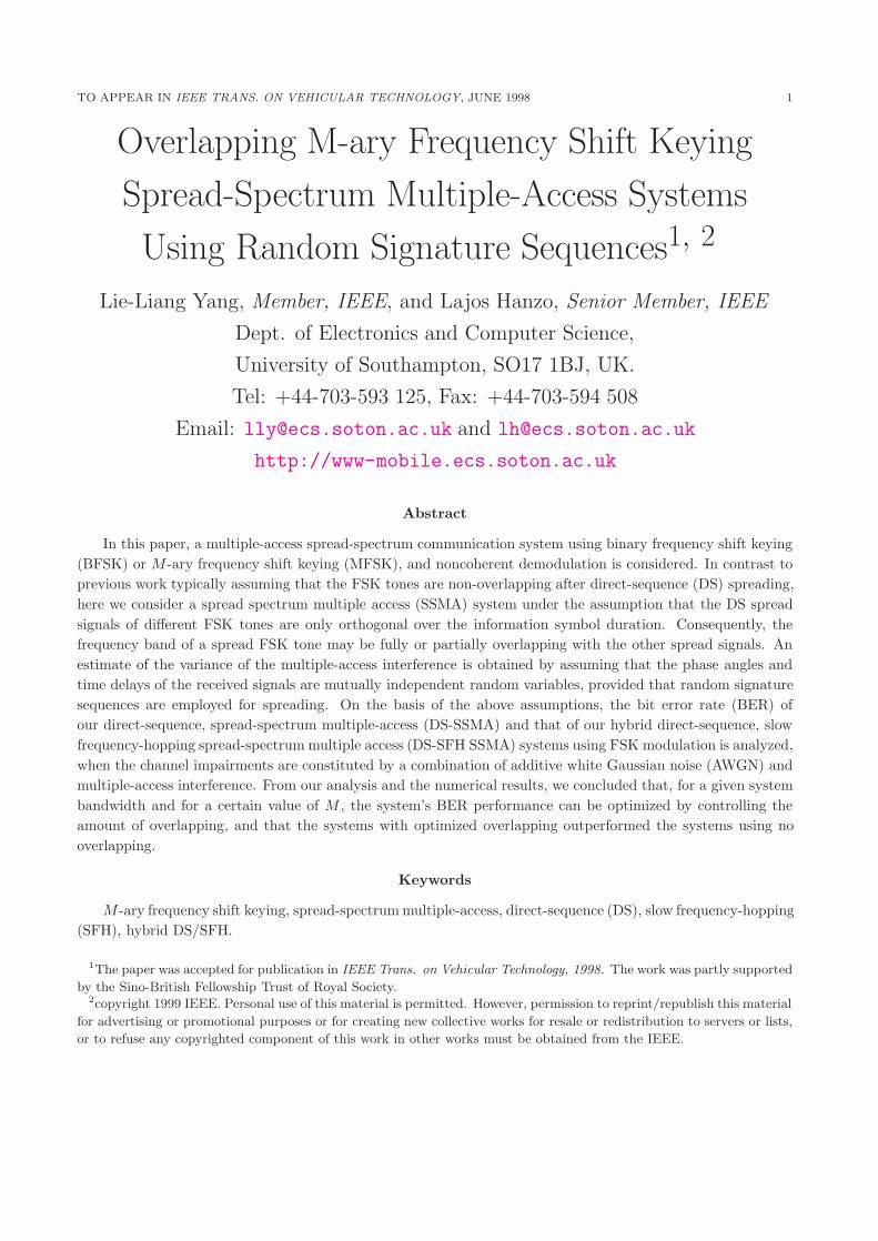
In Fig.7, Imax = 13N log2M
/IU expressed in dB was plotted versus N , the total system spreading
gain, when different values ofM were concerned. The term 13N log2M
was the approximated lower-
bound interference variance from an interfering signal of the conventional MFSK DS-SSMA
system with non-overlapping tones, as noted previously, while IU was the optimum (minimum)
upper-bound of Var[Ic,m(k, 1)] for a given M and N , which was quantified by Eq.(19). It can be
observed from the results of Fig.7, and also from the results of Fig.4 to Fig.6 that the achievable
multiple-access interference reduction due to using overlapping tones is on the order of 0.5-1.5dB
for a single interfering signal, depending on the value of M , rather than on the system’s total
bandwidth. As observed in the Figure, there is no improvement, as the total system spreading
gain, N increases. This is particularly pronounced for the systems employing a sufficiently high
DS spreading bandwidth, or in other words, when the value of NB or NM computed from N
was high enough. In addition, we can conclude that the BER performance improvement due
to increasing the total system bandwidth (or N ) is the same, whether overlapping frequency
tones or conventional non-overlapping frequency tones are employed by the MFSK DS-SSMA
TO APPEAR IN IEEE TRANS. ON VEHICULAR TECHNOLOGY, JUNE 1998 13
systems.
In Fig.8 the BER versus the bit energy-to-noise ratio of Eb/N0 was plotted for the binary FSK
DS-SSMA system with a bandwidth expansion factor of N = 256 and for K = 10, 30, 50, 100
users. In Fig.9, the upper-bound and the lower-bound bit error probabilities of the M-ary FSK
DS-SSMA system using overlapping frequency tones, and that of the conventional system using
non-overlapping tones were plotted versus Eb/N0 with the above parameters of N = 256, K =
10, 50, 100 for an 8-ary FSK system. Note that the upper-bound and the lower-bound of the
bit error probabilities were computed by assuming that the frequency tones were optimally
overlapped and hence the variance of multiple-access interference was minimized. As expected,
the results show that the bit error performances degrade, as the number of active users K
increases and the proposed system with overlapping frequency tones achieves a lower BER,
than the conventional system using non-overlapping tones, provided that the frequency tones
are optimally overlapped. Taking an 8-ary FSK system with K = 50 users as an example, the
DS-SSMA system with MFSK tones optimally overlapped needs 3-4 dB less SNR per bit, than
the conventional system in order to achieve the same BER of 1× 10⁻⁴.
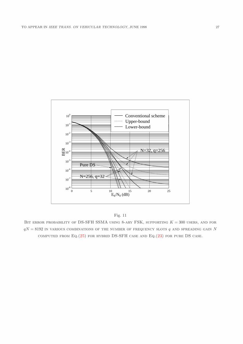
In Fig.10, we plotted the BER of a binary FSK scheme, while in Fig.11 the upper-bound and
lower-bound BER of an 8-ary FSK hybrid DS-SFH system. The Figures were plotted versus
bit energy-to-noise ratio Eb/N0, assuming K = 100 (Fig.10), K = 300 (Fig.11), and a constant
product of qN = 8192, where q was the number of frequency slots of the frequency hopping
pattern, while N was the frequency band expansion factor of each frequency slot. Note that,
N = 8192, q = 1 indicated a pure DS-SSMA system, which marked as ‘Pure DS’ in the Figures.
From the results we can infer that, as shown in the pure DS-SSMA case of Fig.8, 9, the DS-
SFH SSMA system with the MFSK tones optimally overlapped achieves a lower BER than
the conventional DS-SFH SSMA system using non-overlapping tones. Moreover, the bit error
performance improvement depends mainly on the DS spreading. This conclusion was shown in
numerous papers [8]-[11] related to the analysis of hybrid DS-SFH SSMA systems, under the
assumption of perfect power control.
In conclusion, we provided explicit formulae for the performance of BFSK and MFSK DS-
SSMA as well as for DS-SFH SSMA with non-overlapped and partially overlapped frequency
tones. The optimum frequency overlap was also determined. The approach can be used for
direct sequence spread spectrum systems with MFSK modulation to minimize the partial band
jamming by optimizing the frequency tones’ overlap, and the work can be extended to the
analysis of multi-carrier CDMA systems, which use overlapping frequency bands.
Appendix
I. Simplification of The In-phase Component Zc,m
This Appendix shows, how to obtain and simplify the in-phase component of Eq.(6). We
assume that the data bit b0 is sent by the reference user in the first bit period, and the phase
angle is ϕm when b0 = m. Then substituting r(t) from Eq.(4) into Eq.(6), and simplifying it,
TO APPEAR IN IEEE TRANS. ON VEHICULAR TECHNOLOGY, JUNE 1998 14
we obtain:
Zc,m =
√P
2T
δ(b0,m) cosϕm +
√P2T
−1 ∫ T
0n(t)a1(t) cos[2π(fc +m∆)t]dt
+K∑k=2
1
T
∫ T
0a1(t)ak(t− τk) cos {2π[bk(t− τk)−m]∆t+ ϕk(t)} dt
}. (27)
Let us assume that b(k)−1 and b
(k)0 are the data bits transmitted by the kth user in the time
interval [0, τk] and [τk, T ] relative to the reference signal, and ϕ(k)−1 and ϕ
(k)0 are the phase angles
of the kth signal for transmitting the data bits b(k)−1 and b
(k)0 . The third term of Eq.(27) can be
expressed by the partial correlation method [3]. Hence, Eq.(27) can be written as:
Zc,m =
√P
2T
{δ(b0,m) cosϕm +
√P2T
−1 ∫ T
0n(t)a1(t) cos[2π(fc +m∆)t]dt
+K∑k=2
[1
T
∫ τk
0a1(t)ak(t− τk) cos
[2π(b
(k)−1 −m)∆t+ ϕ
(k)−1
]dt
+1
T
∫ T
τka1(t)ak(t− τk) cos
[2π(b
(k)0 −m)∆t+ ϕ
(k)0
]dt.
]}. (28)
II. Variances of the Partial Cross-Correlation Functions
In this Appendix, we will analyze the continuous partial cross-correlation functions of Eqs.(11)
and (12) and show how to compute their expectations by assuming that the phase angles and
time delays are modeled as mutually independent random variables, each of which is uniformly
distributed over the appropriate interval. We can find the variance of the multiple-access inter-
ference term of Eqs.(11) and (12) by computing the expectations of the square of:
R(τ, x, ϕ) =∫ τ
0ai(t)ak(t− τ) cos(2πx∆t+ ϕ)dt, (29)
and
R̂(τ, x̂, ϕ) =∫ T
τai(t)ak(t− τ) cos(2πx̂∆t+ ϕ)dt. (30)
Below we only analyze the expectation of R(τ, x, ϕ), the expectation of R̂(τ, x̂, ϕ) can be
obtained following the same approach.
From Eq.(29) we have:
R(τ, x, ϕ) =l∑
j=0
ai(j)ak(G− l − 1 + j)∫ jTc+τ−lTc
jTccos(2πx∆t+ ϕ)dt
l−1∑j=0
ai(j)ak(G− l + j)∫ (j+1)Tc
jTc+τ−lTccos(2πx∆t+ ϕ)dt, (31)
where lTc ≤ τ < (l + 1)Tc and G = NB or NM for BFSK or MFSK, respectively, representing
the number of chips per data symbol period or the bandwidth-expansion factor per spread FSK
TO APPEAR IN IEEE TRANS. ON VEHICULAR TECHNOLOGY, JUNE 1998 15
tone. Upon evaluating the integrals in Eq.(31), we find that:
R(τ, x, ϕ) = (τ − lTc)sinc[πx∆(τ − lTc)]l∑
j=0
ai(j)ak(G− l − 1 + j) cosβka(j, τ)
+[(l + 1)Tc − τ ]sinc[πx∆((l + 1)Tc − τ)]l−1∑j=0
ai(j)ak(G− l + j) cosβkb(j, τ), (32)
where
βka(j, τ) = πx∆(2jTc + τ − lTc) + ϕ,
βkb(j, τ) = πx∆((2j + 1)Tc + τ − lTc) + ϕ.
The expression of R2(τ, x, ϕ) is computed from Eq.(32) as:
R2(τ, x, ϕ) = (τ − lTc)2sinc2[πx∆(τ − lTc)][
l∑j=0
a2i (j)a
2k(G− l − 1 + j) cos2 βka(j, τ)
+l∑
r=0
l∑s=0s 6=r
ai(r)ak(G− l − 1 + r)ai(s)ak(G− l − 1 + s) cosβka(r, τ) cosβka(s, τ)
Upon evaluating the resulting integral we find that:
γ(x) =G
4πx2∆2[1− sinc(2πx∆Tc)] . (35)
TO APPEAR IN IEEE TRANS. ON VEHICULAR TECHNOLOGY, JUNE 1998 16
The corresponding expression for γ̂(x̂) can be obtained by evaluating the expectation of
R̂2(τ, x̂, ϕ) in the same way, as for R2(τ, x, ϕ), and the result is expressed as:
γ̂(x̂) =G
4πx̂2∆2[1− sinc(2πx̂∆Tc)] . (36)
III. Upper-Bound Variance of an Interference Signal
This Appendix shows how to compute the upper-bound variance of an MFSK DS modulated
interference signal inflicted upon the reference signal. For an MFSK DS-SSMA overlapping
system, the maximum interference is experienced by the frequency tones fc±∆, since they are
overlapped by the other frequency tones with the maximum overlapping area for a given value
of i, and consequently experience maximum interference from the interfering signals.
When an interfering signal activates the specific frequency tones, which will inflict inter-
ference upon the desired signal, xk and x̂k can take values corresponding to the set m =
{−M,−(M − 2), . . . ,−2, 0, 2, . . . , (M − 2),M} according to xk = b(k)M,−1−m and x̂k = b
(k)M,0−m
for the given frequency tones of fc ± ∆ of the reference user. Hence, when an independent
information sequence is considered, the upper-bound of Ic,m(k, 1) can be expressed as:
Var[Ic,m(k, 1)]U =1
M
{Var[Ic,m(k, 1; 0, 0)] + Var[Ic,m(k, 1;M,M)]
+2 ·M2−1∑
λ=1
Var[Ic,m(k, 1; 2λ, 2λ)]
}, (37)
Upon simplification using Eq.(14), we finally obtain that:
Var [Ic,m(k, 1)]U =1
M
{1
3(N log2M − i(M − 1))
+N log2M − i(M − 1)
2π2M2i2
[1− sinc
(2πMi
N log2M − i(M − 1)
)]
+
M2−1∑
λ=1
N log2M − i(M − 1)
4π2λ2i2
[1− sinc
(4πλi
N log2M − i(M − 1)
)]}. (38)
IV. Lower-Bound Variance of an Interference Signal
Here, the lower-bound of the interference variance from an interfering signal is computed.
Apparently, the lower-bound is achieved when the desired signal activates frequency tones fc±(M − 1)∆, as argued in Section II-D. Now, from Appendix III, we can deduce that interference
is inflicted upon the reference signal, where xk and x̂k take values corresponding to the set
m = {0, 2, 4, . . . , 2(M − 1)}, and where xk = b(k)M,−1 −m and x̂k = b
(k)M,0 −m. Hence, when an
independent information sequence is considered, the lower-bound can be expressed as:
Var[Ic,m(k, 1)]L =1
M·M−1∑λ=0
Var[Ic,m(k, 1; 2λ, 2λ)]. (39)
TO APPEAR IN IEEE TRANS. ON VEHICULAR TECHNOLOGY, JUNE 1998 17