* Size rounded off to the nearest foot BUILDING DIMENSIONS CAUTION: SOME PARTS HAVE SHARP EDGES. CARE MUST BE TAKEN WHEN HANDLING THE VARIOUS PIECES TO AVOID A MISHAP. FOR SAFETY SAKE, PLEASE READ SAFETY INFORMATION PROVIDED IN THIS MANUAL BEFORE BEGINNING CONSTRUCTION. WEAR GLOVES WHEN HANDLING METAL PARTS. 713771207 Model No. VT1421-A 697.68612-A VT1431-A 697.68613-A Owner's Manual & Assembly Instructions BX01 Exterior Dimensions Interior Dimensions *Approx. Foundation Storage Area (Roof Edge to Roof Edge) (Wall to Wall) Size Size Sq. Ft. Cu. Ft. Width Depth Height Width Depth Height 14' x 21' 164" x 255 1/2" 291 2527 169" 260 3/4" 116" 164" 255 1/2" 114 1/2" 14' x 31' 164" x 370 1/2" 422 3663 169" 375 3/4" 116" 164" 370 1/2" 114 1/2" 4,3m x 6,4m 4,17m x 6,49m 27,0m 71,6m 4,29m 6,62m 2,95m 4,17m 6,49m 2,91m 4,3m x 9,5m 4,17m x 9,41m 39,2m 103,7m 4,29m 9,54m 2,95m 4,17m 9,41m 2,91m 2 3 2 3
Transcript
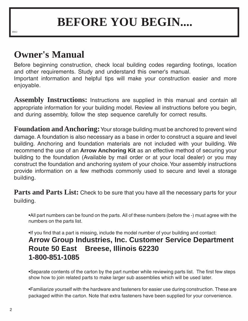
* Size rounded off to the nearest footBUILDING DIMENSIONS
CAUTION: SOME PARTS HAVE SHARP EDGES. CAREMUST BE TAKEN WHEN HANDLING THE VARIOUS PIECESTO AVOID A MISHAP. FOR SAFETY SAKE, PLEASE READSAFETY INFORMATION PROVIDED IN THIS MANUALBEFORE BEGINNING CONSTRUCTION. WEAR GLOVESWHEN HANDLING METAL PARTS.
713771207
Model No. VT1421-A 697.68612-A VT1431-A 697.68613-A
Owner's Manual & Assembly Instructions BX01
Exterior Dimensions Interior Dimensions *Approx. Foundation Storage Area (Roof Edge to Roof Edge) (Wall to Wall)
Size Size Sq. Ft. Cu. Ft. Width Depth Height Width Depth Height
14' x 21' 164" x 255 1/2" 291 2527 169" 260 3/4" 116" 164" 255 1/2" 114 1/2"14' x 31' 164" x 370 1/2" 422 3663 169" 375 3/4" 116" 164" 370 1/2" 114 1/2"
4,3m x 6,4m 4,17m x 6,49m 27,0m 71,6m 4,29m 6,62m 2,95m 4,17m 6,49m 2,91m 4,3m x 9,5m 4,17m x 9,41m 39,2m 103,7m 4,29m 9,54m 2,95m 4,17m 9,41m 2,91m
2 3
2 3
2
Owner's ManualBefore beginning construction, check local building codes regarding footings, locationand other requirements. Study and understand this owner's manual.Important information and helpful tips will make your construction easier and moreenjoyable.
Assembly Instructions: Instructions are supplied in this manual and contain allappropriate information for your building model. Review all instructions before you begin,and during assembly, follow the step sequence carefully for correct results.
Foundation and Anchoring: Your storage building must be anchored to prevent winddamage. A foundation is also necessary as a base in order to construct a square and levelbuilding. Anchoring and foundation materials are not included with your building. Werecommend the use of an Arrow Anchoring Kit as an effective method of securing yourbuilding to the foundation (Available by mail order or at your local dealer) or you mayconstruct the foundation and anchoring system of your choice. Your assembly instructionsprovide information on a few methods commonly used to secure and level a storagebuilding.
Parts and Parts List: Check to be sure that you have all the necessary parts for yourbuilding.
•All part numbers can be found on the parts. All of these numbers (before the -) must agree with thenumbers on the parts list.
•If you find that a part is missing, include the model number of your building and contact:
Arrow Group Industries, Inc. Customer Service DepartmentRoute 50 East Breese, Illinois 622301-800-851-1085
•Separate contents of the carton by the part number while reviewing parts list. The first few stepsshow how to join related parts to make larger sub assemblies which will be used later.
•Familiarize yourself with the hardware and fasteners for easier use during construction. These arepackaged within the carton. Note that extra fasteners have been supplied for your convenience.
BEFORE YOU BEGIN.... BW2
3
Selecting and Preparing Your Site: Before assembly, you will want to decide ona location for your building. The best location is a level area with good drainage.
•Allow enough working space for ease of moving parts into position during assembly. Be sure therewill be enough space at entrance for doors to open fully and enough space around the building tobe able to fasten the panel screws from the outside.
•Before you begin the first steps in assembling your parts, a foundation should be constructed andan anchoring system should be ready to use.
Watch the Weather: Be sure the day you select to install your building is dry and calm.Do not attempt to assemble your building on a windy day. Be careful on wet or muddy ground.
Teamwork: Whenever possible, two or more people should work together to assembleyour building. One person can position parts or panels while the other is able to handle thefasteners and the tools.
Tools and Materials: These are some basic tools and materials you will need for theconstruction of your building. Decide which method of anchoring and the type of foundationyou wish to use in order to form a complete list of the materials you will need.
Foundation Preparation• Hammer and Nails• Spade or Shovel• Hand Saw / Power Saw• Lumber and/or Concrete
Required• Eye Goggles• No. 2 Phillips Screwdriver(With Hardened Magnetic Tip)Note: A power screwdriver or vari-able speed drill with Phillips-tip at-tachment can speed assembly byas much as 40%.
PLAN AHEAD.... A3
4
Safety precautions are important to follow throughout the construction of your building.
•Care must be taken when handling variouspieces of your building since some containsharp edges. Please wear work gloves, eyeprotection and long sleeves when assemblingor performing any maintenance on your build-ing.
•Practice caution with the tools being used in theassembly of this building. Be familiar with theoperation of all power tools.
•Never concentrate your total weight on theroof of the building. When using a step laddermake sure that it is fully open and on evenground before climbing on it.
•Keep children and pets away from worksite toavoid distractions and any accidents whichmay occur.
•Do not attempt to assemble the building if partsare missing because any building left partiallyassembled may be seriously damaged by lightwinds. Call 1-800-851-1085
•Do not attempt to assemble the building on awindy day, because the large panels acting as a"sail", can be whipped about by the wind makingconstruction difficult and unsafe.
SAFETY FIRST.... A4
safety edge
safety edge
sharp edge
sharp edge
Finish: For long lasting finish, periodically clean and wax the exterior surface. Touch-up scratches as soon as you notice them on your unit. Immediately clean the area witha wire brush; wash it and apply touch-up paint per manufacturer's recommendation.
Roof: Keep roof clear of leaves and snow with long handled, soft-bristled broom. Heavyamounts of snow on roof can damage building making it unsafe to enter.
Doors: Always keep the door tracks clear of dirt and other debris that prevent them fromsliding easily. Lubricate door track annually with furniture polish or silicone spray. Keepdoors closed and locked to prevent wind damage.
Fasteners: Use all washers supplied to protect against weather infiltration and to protectthe metal from being scratched by screws. Regularly check your building for loose screws,bolts, nuts, etc. and retighten them as necessary.
Moisture: A plastic sheet (vapor barrier) placed under the entire floor area with goodventilation will reduce condensation.
Other Tips....• Wash off inked part numbers on coated panels with soap and water.• Silicone caulking may be used for watertight seals throughout the building.
Do not store swimming pool chemicals in your building. Combustibles andcorrosives must be stored in air tight approved containers.
Keep this Owner's Manual and Assembly Instructions for future reference.
5
CARE & MAINTENANCE.... BW05
6
ACCESSORIES.... BW06 Web
* Some drilling required to fit buildings without mid-wall bracing.
Model No. SS404• Makes 8" to 12" (20-30cm) wide shelves in any length.• Brackets, braces, hardware included. Lumber is not included.
Model No. SS900-A• Grey color• 3 shelves• Holds up to 85 lbs. (38kg) (even weight distribution)
Heavy-duty, galvanized steel shelf units help organize storagespace. They easily mount on the wall or sit on the floor. Fits allArrow buildings.*
SHELF UNITS
Model No. AK100New concrete anchor system permitsanchoring any size Arrow buildingdirectly to a concrete slab. Each kitcontains heavy-duty, hot-dippedgalvanized steel corner gussets andperimeter clips which fit over the floorframe and lag bolt into a concrete slab.Full assembly instructions and a 1/4"masonary drill bit are included.
TOOL HANGING RACKModel No. TH100The perfect tool organizer. Twin25 1/2" (65cm) steel channelsplus five heavy-duty snap-inhangers and a small tool holder forscrewdrivers, pliers, etc. Holdersslide along channel for fullyadjustable spacing. Great forgarage, basement, or the backof any door. Fits all Arrowstorage buildings.
ANCHOR KITSModel No. AK4Anchor Kit contains heavy-duty steelaugers, 60' (18m) of steel cable and 4 cableclamps. No digging or concretepouring, just insert cable under roof,over roof beams, into augers and twistaugers into the ground. For buildingslarger than 10'x9', use 2 kits.
Model No. AK600Earth Anchor Kit anchors any sizeArrow building to the ground.Each kit contains heavy duty,hot-dipped galvanized steelcorner gussets and 4 earth anchors.
THIS
PAGE
WAS
LEFT
BLANK
INTENTIONALLY
7
THIS
PAGE
WAS
LEFT
BLANK
INTENTIONALLY
8
The Foundation For Your Building
9
Foundation BX9
Concrete Slab
The slab should be at least 4" (10cm) thick. It must be level and flat to provide good support for the frame.The following are the recommended materials for your foundation.● 2 x 4's (5cm x 10cm) (will be removed once the concrete cures)● Concrete ● Sheet of 6 mil plastic● We recommend for a proper strength concrete to use a mix of: 1 part cement ● 3 parts pea sized gravel ● 2 1/2 parts clean sand
Prepare the Site/Construct a Foundation1. Dig a square, 6" (15cm) deep into the ground (remove grass).2. Fill up to 4" (10cm) in the square with gravel and tamp firm.3. Cover gravel with a sheet of 6 mil plastic.4. Construct a wood frame using four planks of 2x4 (5cm x 10cm) lumber.5. Pour in concrete to fill in the hole and the frame giving a total of 4" (10cm) thick concrete. Be sure surface is level.
Allow 3 - 5 hours for construction and a week for concrete curing time.
Note: Before beginning construction, check local building codesregarding footings, location and other requirements.
164"4,17m
FRONT (ROLL-UP DOOR)
21' - 255 1/2"
6,49m
31' - 370 1/2"
9,41m
Note: Finished Slab dimensions, with lumber removed.
ReinforcingRods
ReinforcingRods
Optional Footer Type of Foundation
Welded WireFabric
It is important that the entire floor frame be anchored after the building is erected.Below are recommended ways of anchoring.
Anchoring Down The Building
AnchoringBX10
Arrow Anchoring Kit: (Model No. AK100 or 68383)Recommended for use with the concrete foundation.Contains: Corner gussets, perimeter clips, hardware,1/4" masonary drill bit and installation instruction.
Anchoring into Concrete:1. For poured concrete slab or footing or patio blocks:Use 1/4" x 2" Lag Screws.2. For Anchor Post of Concrete poured after building iserected: Use 1/4" x 6" Lag Screws.
Arrow Anchoring Kit: (Model No. AK4 or 60298)Recommended for use with any suggested base.Contains: 4 Anchors with Cable, Clamps andinstallation instruction.
Anchoring into Wood/Post:Use 1/4" Wood Screws. There are 1/4" (0,63cm) dia.holes provided in the frames for proper anchoring.
10
OVER THE BEAMSAND INTO THE GROUND
1. 2.
1. 2.
11
66769Door Slide (2)
66382Lower Door Guide (2)
7972Door Handle
Lock Bracket (1)
7022Eave Bracket
4 (14x21)8 (14x31)
66646Washer
960 (14x21)1400 (14x31)
66444Roof Trim Cap(2 right & 2 left)
66446 (Arrow Logo)Peak Cap (2)
65914#6Ax7/8"Screw (4)
65900A#10Bx1/2" Black Screw (4)
65408#10-32x1/4" Bolts (3)
659891/4-20x1/2" Hex Head Bolt
134 (14x21)256 (14x31)
Hardware for Building BX11
66098Plastic Spacer (6)
65004#8Ax5/16" Screw
813 (14x21)1092 (14x31)
65106#10-32 Square Nut
505 (14x21)677 (14x31)
651011/4-20 Square Nut
132 (14x21)254 (14x31)
65958#8-32x7/8" Bolt (2)
Weather Stripping67293 (1)
67545 (1 14x21) (2 14x31)
66260Handle (2)
KIT 2
65943#10-32x7/16" Bolt
502 (14x21)674 (14x31)
KIT 3 WASHER KIT
KIT 1
HARDWARE SUB KIT
REMAINING HARDWARE PIECES
65103#8-32 Hex Nut (2)
Remove from bag and savefor Step 24
674883/16 x 1 5/16"
Heavy "S" Hook(2)
66464 (2)1/4-20x1 1/2" Hex Head
Bolt
Parts List
12
Assembly Part PartKey No. Number Description Carton 1 Carton 2 Carton 3 Carton 4 Carton 5
1 7023 Left Roof Trim 2 2 7024 Right Roof Trim 2 3 7562 Track 1 4 9471 Wall Panel 2 5 9472 Corner Panel 4 6 9473 Front Wall Panel 2 7 9477 Door Jamb 2 8 9488 Right Door Jamb 1 9 9489 Left Door Jamb 110 9494 Right Gable 211 9495 Left Gable 212 10490 Door 113 10505 Horizontal Door Brace 214 9509 Ridge Cap 315 9510 Side Roof Trim 616 9474 Lintel 117 9475 Side Floor Frame 418 9476 Side Wall Channel 619 9484 Right Side Eave Channel 220 9485 Left Side Eave Channel 221 10456 Right Roof Beam 1022 10457 Left Roof Beam 1023 6938 Rear Frame 224 6939 Rear Frame 225 6942 Right Rear Wall Channel 226 6943 Left Rear Wall Channel 227 6947 Column Gusset 628 6954 Gable/Truss Strut 429 6955 Inner Gable Bracket 430 6958 Inner Truss Bracket 431 6959 Outer Truss Bracket 432 6962 Vertical Brace 233 6963 Upper Chord 234 6964 Lower Chord 235 6965 Inner Diagonal Brace 236 6966 Outer Diagonal Brace 237 6967 Splice Plate 138 7003 Left Shear Plate 239 7004 Right Shear Plate 240 7817 Spring Support Bracket 242 9464 Lower Door Track 143 9465 Support Column 244 9466 Wall Channel 245 9467 Ramp 146 9468 Corner Door Channel 247 9469 Side Door Channel 248 9478 Front Column 249 9480 Front Frame 250 9481 Front Frame 251 9482 Right Front Wall Channel 252 9483 Left Front Wall Channel 253 10458 Right Track Support 154 10459 Left Track Support 155 9490 Center Column 656 9496 Outer Gable Bracket 457 9497 Outer Truss Bracket 458 9500 Vertical Door Brace 259 10455 Track Strut 260 9491 Roof Panel 1461 9492 Right Roof Panel 262 9493 Left Roof Panel 263 9470 Wall panel 17
Carton #1 through #5 contain parts for a 14' x 21'. Page 14 contains the additional parts for a 14' x 31'.
BX12
13
Assembly by Key No. for 14x21 BuildingBX13
Additional Parts for & 14' x 31'
14
Carton 6 & 7Assembly Part Part Wayne DaltonKey No. Number Description Door Carton 8 Carton 9
1 Assemble 1/2 truss at a time. At-tach column gusset to lower chordsecurely using #1/4-20x1/2" hex headbolts and square nuts. All other con-nections are to be made loosely.
2 Fasten lower chord to upperchord and eave bracket to upperchord.
3 Fasten vertical brace to lowerchord.
4 Fasten right shear plate and leftshear plate to vertical brace andupper chord.
5 Fasten inner diagonal brace toupper chord and lower chord.
6 Fasten 2 inner truss brackets toupper chord and lower chord andinner diagonal brace as shown.
9 Fasten 2 outer truss bracketsto upper and lower chords.
10 Square up 1/2 truss, adjust andtighten all fasteners.
11Assemble the other half of truss.
12Splice both halves together withthe splice plate and join with (4)#10-32x7/16" bolts and square nutsthrough vertical brace.Make 1 assembly for the 14x21.Make 2 assemblies for the 14x31.
The gables go on top of the front andrear walls to support the roof beams.The center columns support the trussand the framework.
NOTEThe gables are packed nestedtogether and might be mistaken
as one piece. Carefully separatethem before continuing.
1 Attach the inner and outer gablebrackets to the gables using bolts,washers and nuts where shown.
NOTEMounting leg of bracket must face
toward outside of building.
Step 2BX17
● Parts Needed For ●Gables/Column Assemblies
●●●●● 9494 Right Gable (2)●●●●● 9495 Left Gable (2)●●●●● 6955 Inner Gable Bracket (4)●●●●● 9496 Outer Gable Bracket (4)●●●●● 9490 Center Column (6 14x21) (10 14x31)
17
9490
2Align the holes on the centercolumns back to back and fastentogether using 6 bolts and nuts.Make 3 assemblies for the 14x21.Make 5 assemblies for the 14x31.
3Set these pieces aside for later as-sembly.
STEP
2
STEP
1
STEP
3
9490
6955
9496
Washer
9494
9495
Attach Narrow Flangeof Gable Brackets
to Gable
6955
9496
FRONT
Washer
The roof beams join the gables to thetruss and supports the roof panels.
1 Align the holes on a left and rightroof beam back-to-back and fastentogether using 8 bolts and nuts. Make10 assemblies.
2 On the 14x31 fasten roof beamstogether in the same manner. Make5 assemblies.
Step 3BX18
● Parts Needed For ●Roof Beam Assemblies
●●●●● 10456 Right Roof Beam (10)●●●●● 10457 Left Roof Beam (10)●●●●● 9462 Roof Beam (10 14x31)
18
STEP
2
STEP
1
9462
9462Align End Holes
Before TighteningBolts and Nuts
Small Holeson Top
10456
10457
EndView
Assembled
1 Place the floor frame pieces on thefoundation. Assemble the 4 cornersof the floor frame using 3 bolts fromthe bottom with nuts on top at eachcorner as shown.
Step 4BX19
● Parts Needed For ●Floor Frame Assembly
●●●●● 9481 Front Frame (1)●●●●● 9480 Front Frame (1)●●●●● 9475 Side Floor Frame (4)●●●●● 6939 Rear Frame (1)●●●●● 6938 Rear Frame (1)●●●●● 9460 Side Floor Frame (2 14x31)
19
6938
6939
9475
9460
9475
9480
9481
9475
9460
9475
(1431)
9475
9475
9475
9475
9480
9481
FRONT
6938
6939
(1421)
STEP
1
1 Fasten side floor frames togetherwith a column gusset using 2 boltsfrom the bottom and nuts on top. Atrear of building, repeat procedure.
2 Position center column assem-blies where floor frames are joinedand fasten to gusset with 8 bolts.
Repeat procedure on sides of build-ing for the 14x31.
NOTESupport center columns with
stakes or other means until wallpanels are attached.
3 Measure the floor frame diago-nally. When the diagonal measure-ments are equal, the floor frame issquare.
Step 5BX20
● Parts Needed For ●Gusset/Center Column
20
STEP
2
NOTEDo not fasten the floor frames to
your foundation at this time.You will anchor the building
after it is erected.
The floor frame must be squareand level or holes will not align.
●●●●● 6947 Column Gusset (3 14x21) (5 14x31)●●●●● Center Column Assembly (3 14x21)●●●●● Center Column Assembly (5 14x31)
6947STEP
3
9490
9490
6947
(1431)
6947
6947
6947
9490
9490
9490
FRONT
STEP
1
9490
9490
9490
6947 (1421)6947
6947FRONT
NOTEThe remainder of the building
assembly requires many hoursand more than one person. Tie
down and support assemblybefore the end of the work day.A partially assembled buildingcan be severely damaged by
light winds.
Each screw and bolt in the wall re-quires a washer.
1 Position a corner panel at thecorner of the floor frame as shown.The widest part of each corner panelmust be placed along the side of thebuilding for all 4 corners. Fasten thecorner panel to the floor frame with 4screws.
Support the corner panel with a stepladder until a wall panel is attached.
2 Attach the front wall panels to thefront corner panels, as shown.
3 Attach the wall panels to the rearcorner panels, as shown.
NOTEBe careful to install the correct
panel in each position as shown.
4 Double-check the part numbers ofthe wall panels, before proceeding.
The floor frame must be squareand level or holes will not align.
Washer
STEP
4
STEP
2
STEP
3
9473 9473
SIDE SIDE
REAR
FRONT
9472
NarrowSide
STEP
1
Wide Side
TOP VIEW
9473
9472
9472
9472
94719471
Crimped RibUnderneath
9472
9471
9472
9471
9473
9472
9472
The mid frame pieces give rigidity tothe sides and rear wall.
NOTE Before installing side wall
channels decide at which locationyou want the side entrance door.Do not install the 1x4 side wall
channels at 1 of the 4 corner loca-tions.
1 Fasten side wall channels tocenter columns using 2 bolts and tocorner panels using 4 screws.
2 Overlap with the right and leftfront wall channels and fasten tofront wall panel using 3 screws. Donot fasten hole nearest door open-ing.
3 Overlap with right and left rearwall channels and fasten to columnand wall panel.
4 Fasten overlaps using 4 bolts andnuts in each corner assembly.
Step 7BX22
● Parts Needed For ●Mid Frames
●●●●● 9482 Right Front Wall Channel (2)●●●●● 9483 Left Front Wall Channel (2)●●●●● 9476 Side Wall Channel (6)●●●●● 6942 Right Rear Wall Channel (2)●●●●● 6943 Left Rear Wall Channel (2)
22
STEP
2
STEP
5
STEP
19465
5 Install support column to sidefloor frame and side door channelfastening channel to center column.Install 2nd support column to sidefloor frame and corner door chan-nel. Fasten channel to corner paneland left rear wall channel.
69439468
6942
9469
9476
9476
9476
9482
9483
FRONT
STEP
3
STEP
4
NOTEOn the 1431, attach the sidewall channel between thecenter columns using bolts
and nuts.
9461
●●●●● 9465 Support Column (2)●●●●● 9469 Side Door Channel (2)●●●●● 9468 Corner Door Channel (2)●●●●● 9461 Side Wall Channel (4 14x31)
9461
FRONT
1 Position right side eave channelagainst support columns. Fastenchannel to corner panel. Fasten col-umns to side eave channel using 2bolts and nuts on each column.
2 Position lower door track insidethe side floor frame. Overlap withramp and fasten from the bottom us-ing (3) #10-32x1/4" slotted head boltsand square nuts.
3 Position track inside right sideeave channel, directly over lower doortrack and ramp, and fasten using 4screws where shown.
Step 8BX23
● Parts Needed For ●Side Door Frames
●●●●● 9484 Right Side Eave Channel (1)●●●●● 7562 Track (1)●●●●● 9467 Ramp (1)●●●●● 9464 Lower Door Track (1)
23
STEP
2
STEP
3
STEP
1
1/2" BetweenRamp & Panel
Notch TowardOutside ofBuilding
7562
OpeningFacing In
Long Legon Top
Short Legon Bottom
9484
9467
9464
1 Fasten front frames at the top tofront wall panels with 3 screws. Donot fasten hole nearest door openingat this time.
2 Fasten front columns to the frameat bottom and channel with 2 bolts.
Hint: Pull front wall panel slightlyaway to tighten bolts.
3 Position lintel across top of frontframes and fasten with 2 bolts andnuts on both sides.
4 Position column gusset over rearcolumns and fasten with 8 bolts. At-tach rear frames to gusset using 2bolts and opposite end to wall panelusing 3 screws.
Step 9BX24
● Parts Needed For ●Front/Rear Frames
24
STEP
1
●●●●● 9474 Lintel (1)●●●●● 9481 Front Frame (1)●●●●● 9480 Front Frame (1)●●●●● 9478 Front Column (2)●●●●● 6947 Column Gusset (1)●●●●● 6938 Rear Frame (1)●●●●● 6939 Rear Frame (1)
STEP
2
STEP
4
9480
STEP
3
9478
9474
9481
6938
6939
6947
1 Position Truss Assembly on build-ing by sliding column gussets overcenter columns and fasten with 8bolts and nuts on each gusset.
2 Position right and left side eavechannels over eave brackets andfasten with a bolt and nut. Front andrear frames overlap side eave chan-nels. Fasten overlaps with 3 boltsand nuts. Fasten corner panels tochannels using 4 screws.
NOTEOn the 1431, fasten the side
eave channels over eave bracketsusing bolts and nuts.
Step 10BX25
● Parts Needed For ●Truss/Top Frames
●●●●● Truss Assembly (1 14x21) (2 14x31)●●●●● 9484 Right Side Eave Channel (2)●●●●● 9485 Left Side Eave Channel (2)●●●●● 9463 Side Eave Channel (2 14x31)
25
STEP
2
STEP
1
9485
(1421) 9484 Installed in Step 8
9485
9484
9463
9463
(1431)
Each wall panel has a crimped rib on1 side. The crimped rib should gounder the rib of the panel that followsit.
1 Fasten the wall panels at the topand bottom with screws.
2 Fasten the center of each panel tothe wall channel with screws. Fastenoverlapping ribs using screws andbolts with nuts.
3 When you have attached all wallpanels in the correct positions, thebuilding will look like this.
4 Fasten right and left track sup-ports to the front columns using 5bolts from the inside and nuts out-side.
NOTEFlanges on track supports mustface towards front of building.
Step 11BX26
● Parts Needed For ●Walls Panels/Track Supports
●●●●● 9470 Wall Panel (17 14x21) (8 14x31)●●●●● 10458 Right Track Support (1)●●●●● 10459 Left Track Support (1)
26
STEP
3
STEP
1
9470
STEP
2
STEP
4
10458
10459
10459
INSIDEBUILDING
Bolt and nutdoes not gothru wall channelat overlap
Detail ShowingCenter of Panel Screwed
to Wall Channel
Crimped RibUnderneath
Step 12BX27
● Parts Needed For ●Wall Channel/Door Jamb
●●●●● 9477 Door Jamb (2)●●●●● 9466 Wall Channel (2)
27
Top View
The door jambs reinforce the dooropening and provide an attractivetrim. Follow these steps for both doorjambs.
1Place wall channels behind wallpanel, large hole towards door open-ing. Loosen wall panel and fastenwall channels to side wall channelsusing 1 screw, under panel. Replacepanel and fasten wall channels topanel using 3 screws.
2Overlap the rib of wall panel with adoor jamb and fasten at top to sideeave channel and bottom to side floorframe using #6Ax7/8" screws andspacers. Positon spacer inside wallpanel rib and channel or frame.
3Fasten door jamb at middle holesusing #8-32x7/8" bolts, spacers andhex nuts. Spacer is positioned be-tween wall panel rib and wall chan-nel.
4Fasten outer flange of door jamb towall panel using 4 screws.
STEP
4
STEP
1
7/8" Bolt STEP
3
Spacer
9466
9466
STEP
2
Top View
Spacer
7/8" Screw
Door Track
9477
Wall Channel
FRONT
Step 13BX28
● Parts Needed For ●Gable/Roof Beams
●●●●● Right Gable Assembly (1)●●●●● Roof Beam Assembly (2)
28
STEP
2
1Lift and fasten a right gable assem-bly at top of lintel using bolts andnuts.
2Spread the 2 halves of a roof beamassembly and fasten the roof beam tothe outer gable bracket using 2 boltsand nuts.
Hint: The holes along the length ofthe beam must be on the top surfaceand 4 hole cluster must be fastenedtoward truss.
3Fasten the outer end of the roofbeam to the outer truss bracket of thetruss using 2 bolts and nuts.
Repeat Steps 2 through 3 for the nextroof beam assembly.
4 holes toward truss
STEP
3STEP
1
2" 5cm
29
●●●●● Roof Beam Assembly (8)●●●●● Left Gable Assembly (2)●●●●● Right Gable Assembly (1)●●●●● 9462 Roof Beam Assembly (5 14x31)
● Parts Needed For ●Gables/Roof BeamsStep 14
STEP
1
STEP
STEP
2
3
BX29
1Lift and fasten a left gable assem-bly in the same manner.
2Join the left and right gables to-gether using a bolt and nut in thethird hole from the bottom only.
3Apply the weather strippingalong the mating edge of the left andright gables as shown. Cut theweather stripping to length.
4Install roof beam assemblies tothe left side of building in the samemanner. Slide a roof beam assem-bly over center gable flange andother end over shear plates on trussand fasten as before.
Repeat roof beam procedure for theopposite end of building. Note that 4hole cluster in roof beam assembly,must be fastened toward truss.
STEP
4
NOTEOn the 1431, attach the roof
beams between the trussassemblies as before
(1421)
WeatherStripping
Tape
4 holes toward truss
(1431)
9462
30
●●●●● 6954 Gable-Truss Strut (4 14x21) (2 14x31)
● Parts Needed For ●Gable-Truss StrutStep 15
STEP
1
STEP
STEP
2
3
BX30
1Fasten a gable-truss strut to themiddle roof beam behind the frontgable by placing tab on the end of thestrut between the roof beams. Alignthe tab with the holes and fasten thestrut with 2 bolts and nuts.
2Fasten the lower end of the strut tothe center gable flange with 2 bolts.
Repeat Steps 1 and 2 for the oppo-site end of building.
3At the truss assembly the gablestruts are attached between themiddle roof beam and the verticalbrace.
NOTEDo not tighten bolts and nuts until
all Struts are assembled
69546954 6954
(1421)
(1431)
6954
31
Squaring the BuildingStep 16
STEP
1
STEP
2
3
BX31
STEP
4
5
1Square the building on the founda-tion and at the top, by measuringdiagonally from corner to corner aspreviously done.
2Use string to check and see if thesides and rear of building are straight,not bowed inward or outward.
3Level the full perimeter of the floorframe. Shim under with wood shin-gles if necessary.
4Square the front of building as pre-viously done for base.
5Anchor front frame to concrete with1/4" diameter expandable anchorbolts or other means, where shown.
NOTEThe 107" (2,72m) door opening
must be held for proper dooralignment. Measure betweenthe left and right track support.
STEP
STEP Use String To StraightenSide Before Anchoring
Measure DiagonallyFor Squareness
Left TrackSupport
Right TrackSupport107"
2,72m
107"2,72m
32
● Parts Needed For ●Left/Right Roof PanelsStep 17
STEP
2
BX32
●●●●● 9492 Right Roof Panel (2)●●●●● 9493 Left Roof Panel (2)
Installing the roof panels is best donewith an 8' step ladder. Each screwand bolt in the roof requires a washer.
1Position right and left roof panelsat the front corners and fasten to thegable and roof beams using screwsand bolts as shown. Do not fastenthe lower end of the panels to the sideeave channel at this time.
Hint: Follow the fastener sequenceshown, for proper alignment.
2Install the right and left roof pan-els for the rear corners in the positionshown.
STEP
1
9493
8 thru 119492
12 thru 15
16 thru 19
9492
9493
FRONT
12
34
56
7
NutWasher
Bolt
Gab
le
LEFT ROOF PANEL RIGHT ROOF PANEL
SCREWS TO ROOF BEAM SCREWS TO ROOF BEAM
FASTENTO GABLE
SLOTTED HOLESAT TOP
SMALL HOLESAT BOTTOM
FASTEN ATOVERLAP
FASTENTO GABLE
33
● Parts Needed For ●Roof PanelsStep 18
STEP STEP
3
BX33
●●●●● 9491 Roof Panel (4)
1Position a roof panel overlappingrib of left corner roof panel. Fastenoverlap at center of roof panel ribusing a bolt and nut. Fasten to roofbeams as done before using screws.
2Install a roof panel on the left sideof building. Repeat procedure with 2more roof panels working side toside. At the top beam end of panels,fasten 2nd roof panel rib overlapswith a bolt and nut.
3Cut the weather stripping tapeinto 6 strips, each strip about 2" (5cm)long. Press 2 strips over the boltheads on overlaps at the top of pan-els. Save the other 4 strips for the restof roof.
4Cover the join at the peak withweather stripping tape. Unroll thetape and press it down over the open-ing at the ridge as you install eachroof panel. Do not cut the tape at thistime.
STEP
1
ROOF PANEL
SCREWS TO ROOF BEAM
SLOTTEDHOLES AT
TOP
FASTENAT
OVERLAPFIRST
SCREWS TOROOF BEAM
SMALLHOLES
AT BOTTOM
Weather Stripping Tape9491
Crimped Rib is Always Overlappedby Wide Rib of Adjacent Panel
WeatherStripping
Tape
4
STEP
2
NOTEOn the 1431, cut the weatherstripping tape into 10 strips.
Follow Fastener Sequence
34
● Parts Needed For ●Ridge CapStep 19
BX34
●●●●● 9509 Ridge Cap (1)
1STEP
1Install a ridge cap on the com-pleted roof section using bolts andnuts. Do not fasten the ends of theridge cap at this time.
9509
35
● Parts Needed For ●Roof Panels & Ridge CapStep 20
BX35
●●●●● 9509 Ridge Cap (1)●●●●● 9491 Roof Panel (6)
2STEP
1Install 4 roof panels working sideto side.
NOTEIf roof beam holes do not line up
with the roof panel holes, shift thebuilding from left to right. If this
does not help, your building maynot be level. Shim the corners
until holes line up.
2Unroll the weather stripping tape,press it down firmly, but do not cut.
3Install the second ridge cap over-lapping the first ridge cap. Align theholes and fasten using bolts.
4Install 2 more roof panels. Fasten5th top overlap and cover withweather strip over head of bolt.
9491
3STEP
4STEP
1STEP
9509
36
● Parts Needed For ●Roof Panels/Ridge CapsStep 21
BX36
●●●●● 9509 Ridge Cap (1)●●●●● 9512 Ridge Cap (1 1431)●●●●● 9491 Roof Panel (4 14x21) (12 14x31)
2
1Install 2 more roof panels.
2Install the third ridge cap overlap-ping the second ridge cap as before.Temporarily remove the rear cornerroof panels, and install the remaining2 roof panels. Fasten 7th top over-lap and cover with weather strip overhead of bolt.
3Install the corner roof panels. Fas-ten ridge cap using bolts and nuts.
4Fasten the lower end of the panelsto the side eave channels usingscrews and washers.
9509
9512 (1431)
1On the 1431 install 2 more roofpanels.
2Install the third ridge cap overlap-ping the second ridge cap as before.Install 6 more roof panels, while fas-tening 8th and 9th top overlap andcover with weather strip over head ofbolt. Fasten ridge cap using boltsand nuts.
3Install 2 roof panels, and the fourthridge cap. Temporarily remove therear corner roof panels, and installthe remaining 2 roof panels. Fasten11th top overlap and cover withweather strip over head of bolt.
4Install the corner roof panels. Fas-ten ridge cap using bolts and nuts.
5Fasten the lower end of the panelsto the side eave channels usingscrews and washers.
STEP
3STEP
9491
CutWeather Strippingand Fold Under
4STEP
5STEP
1STEP
37
● Parts Needed For ●Roof TrimStep 22
BX37
●●●●● 7023 Left Roof trim (2)●●●●● 7024 Right Roof Trim (2)●●●●● 9510 Side Roof Trim (6)●●●●● 9513 Side Roof Trim (2 1431)
1Attach the side roof trim to thelower end of the roof panels on eachside of the building using screws ateach panel overlap.
NOTEA single screw fastens both trim
pieces at the overlap.
2Position left and right roof trim tothe ends of roof, noting that trim slipsunder ridge cap, but fits on top of sideroof trim.
3Fasten roof panel rib, trim, peakcap and ridge cap together usingbolts and nuts. Fasten the remainingpeak cap in the same manner.
4Using your thumb and index finger,overbend the bottom flange of theside roof trim at the corner inwardenough so the right and left roof trimcaps fit onto right and left corners.
5Fasten trim to side trim using ascrew and washer into roof panel.
6Fasten the roof trim caps to the sidetrim using a screw.
7024
4STEP
3STEP
2STEP
5STEP
6STEP
7023
Peak Cap
RoofTrimCap 9510
9510
9510
1STEP
Arrow LogoGoes on Front
of Building
9510 9513 9510 9510
(1431)
(1421)
38
● Parts Needed For ●Side Door AssemblyStep 23
BX38
●●●●● 10490 Door (1)●●●●● 10505 Horizontal Door Brace (2)●●●●● 9500 Vertical Door Brace (2)
NOTETo assemble door to slide fromleft to right (opening), positiondoor with handle holes on leftside of door. Position handleholes on right side if door is to
slide from right to left (opening).
Each bolt and screw in the door re-quires a washer.
1Hold the vertical door braceagainst the inside surface of door,align holes, and fasten with 3 screws.
2Repeat Step 1 for remaining verti-cal door brace.
3Attach the handle to the door with 2bolts and nuts, as shown.
4Put a horizontal door brace ontothe top edge and bottom edge andfasten with 2 bolts and nuts on each.
5Attach the lower door guides asshown.
3STEP
STEP
4STEP
5STEP
10505
10490
9500
1STEP
END VIEWSHOWING:
10505
9500
HorizontalDoor Brace
Door
Guide
Washer
2
39
● Parts Needed For ●Door InstallationStep 24
BX39
Door Assembly (1)●●●●● 7972 Door Handle Lock Bracket (1)
1Position door slides onto the legs,from the end of door track, as shownin the end view.
2From inside the building, put thebottom of the door behind door jambinto the lower door track.
3Position the top of the door so thatthe holes in the door line up with theholes in the door slides.
4Fasten the door to the door slidesusing two #10Bx1/2" screws per doorslide.
NOTEThe holes in the door slides allowyou to adjust the door. Place the
door in the middle holes.
5Position door handle lock bracketaligned with handle holes, againstdoor jamb. Using a pencil markthrough holes onto jamb, removebracket and drill (2) 1/4" diameterholes in jamb. Fasten bracket to doorjamb using 2 bolts and nuts.
3STEP
2STEP
5STEP
4STEP
Door Slide
1STEP
7972
Jamb
Door
Door
Track
END VIEWOF TRACK
Door Slide
Lower Door Track
#10Bx1/2" Screw
Horizontal Door Brace
40
● Parts Needed For ●Vertical Tracks Roll-Up-DoorStep 25
BX40
1 Attach right and left vertical tracksloosely to right and left track supportsusing 1/4-20x1/2" hex head bolts andsquare nuts.
NOTEPlease refer to the Wayne DaltonInstruction Manual for assembly ofthe garage door and track compo-nents. This manual is packed withthe garage door. The Arrow Own-
ers Manual will be used for theattachment of the garage door to
the building and for spring, snubber(safety) cable installation.
Right Track Support
Square Nut
49 1/8"
28 1/2"
10"
Jamb Bracket(Short)
Jamb Bracket(Long)
Left Vertical Track
Jamb Bracket(Long)
1/4-20x1/2"Hex Head Bolt
Stud Plate
Flagangle
●●●●● Right Vertical Track●●●●● Left Vertical Track
41
● Parts Needed For ●Roll-Up-DoorStep 26
BX41
●●●●● 7817 Spring Support Bracket (2)●●●●● 10455 Track Strut (2)
STEP
1
STEP
3
1Install spring support brackets tothe roof beams using bolts shown.
2Attach the right and left horizontaltrack to the right and left vertical trackusing bolts and nuts shown, follow-ing Wayne Dalton Instructions.
3Fasten track struts to open holeon truss assembly using 1/4-20x1/2"hex head bolt and square nut. Fas-ten opposite end to spring supportbracket and horizontal track using1/4-20x1/2" hex head bolt and squarenut.
Roof Beam
7817
#10-32 Square Nut
1/4-20 Square Nut
Horizontal Track1/4-20 x 1 1/2"Hex Head Bolt
10-32x7/16" Bolt
#10-32x7/16"Bolt and Nut
Horizontal Track
7817 1/4-20 x 1/2"Hex Head Bolt
1/4-20 x 1/2"Hex Head Boltand Square Nut
10455
1/4-20 Square Nut
42
● Parts Needed For ●Roll-Up-DoorStep 27
BX42
CAUTION:FROM THIS POINT ON, BE SURE
TO USE EXTREME CAUTIONUNTIL THE DOOR IS PROPERLY
SPRUNG AND OPERATING1Attach "S" hooks to both springs.Fasten sheave and sheave fork toopposite ends of springs followingWayne Dalton Instructions. Attachspring assemblies to spring supportbrackets.
Thread cable with one 3 hole clipattached thru a hole in the flagangle,then thru the spring and spring sup-port bracket. Pull tight and attach the3 hole clip to the free end of the cable.
CHECKBe sure that the lift cables do not rub and/or the rollers do notbind in the track when door is opened or closed. Recheck the
springs to be sure that there is equal tension on both springs. Thisis extremely important for proper door operation.
"S" Hook
Spring3/8-16 1 1/4"Hex Head Bolt
7817
3/8-16Hex Nut
Steel Sheave
3 Hole Clip
SnubberCable
Snubber Cable
Flagangle
NOTERecheck all door fasteners andhardware to be sure that eachfastener is tight and secure.
43
Step 28BX43
STEP
2
STEP
1
1Position right and left door jambsto right and left track supports withnotched end on top, facing insidebuilding.
2Fasten long flange to track supportand short flange to front wall panelusing screws and washers.
● Parts Needed For ●Right/Left Door Jambs
●●●●● 9488 Right Door Jamb (1)●●●●● 9489 Left Door Jamb (1)
9489
9488
SOME FACTS ABOUT RUSTRusting is a natural oxidizing process that occurswhen bare metal is exposed to moisture. Problemareas include screw holes, unfinished edges, orwhere scrapes and nicks occur in the protectivecoating through normal assembly, handling anduse. Identifying these natural rusting problem areasand taking some simple rust protection precautionscan help to stop rust from developing, or stop itquickly as soon as it appears.
1. Avoid nicking or scraping the coating surface,inside and out.
2. Use all the washers supplied. In addition to pro-tecting against weather infiltration, the washers pro-tect the metal from being scraped by the screws.
3. Keep roof, base perimeter and door tracks free ofdebris and leaves which may accumulate and retainmoisture. These can do double damage since theygive off acid as they decay.
4. Touch up scrapes or nicks and any area of visiblerust as soon as possible. Make sure the surface isfree of moisture, oils, dirt or grime and then apply aneven film of high quality touch-up paint.