363
OWNER’S MANUAL 2014 FIAT 500e

O W N E R ’ S M A N U A L
2 0 1 4
20
14
FIA
T 5
00
e
14BEV24-126-AD Fourth Edition Printed in U.S.A.
FIAT 500eFCA US LLC
VEHICLES SOLD IN CANADAWith respect to any Vehicles Sold in Canada, the name FCAUS LLC shall be deemed to be deleted and the name FCACanada Inc. used in substitution therefore.
DRIVING AND ALCOHOLDrunken driving is one of the most frequent causes ofaccidents.Your driving ability can be seriously impaired with bloodalcohol levels far below the legal minimum. If you aredrinking, don’t drive. Ride with a designated non-drinking driver, call a cab, a friend, or use public trans-portation.
WARNING!
Driving after drinking can lead to an accident.Your perceptions are less sharp, your reflexes areslower, and your judgment is impaired when youhave been drinking. Never drink and then drive.
This manual illustrates and describes the operation offeatures and equipment that are either standard or op-tional on this vehicle. This manual may also include adescription of features and equipment that are no longeravailable or were not ordered on this vehicle. Pleasedisregard any features and equipment described in thismanual that are not on this vehicle.
FCA US LLC reserves the right to make changes in designand specifications, and/or make additions to or improve-ments to its products without imposing any obligationupon itself to install them on products previously manu-factured.
Copyright © 2016 FCA US LLC
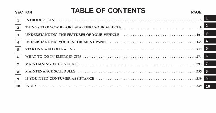
TABLE OF CONTENTSSECTION PAGE
1 INTRODUCTION . . . . . . . . . . . . . . . . . . . . . . . . . . . . . . . . . . . . . . . . . . . . . . . . . . . . . . . . . . . . . . . 3
2 THINGS TO KNOW BEFORE STARTING YOUR VEHICLE . . . . . . . . . . . . . . . . . . . . . . . . . . . . . . . . . . 9
3 UNDERSTANDING THE FEATURES OF YOUR VEHICLE . . . . . . . . . . . . . . . . . . . . . . . . . . . . . . . . . 101
4 UNDERSTANDING YOUR INSTRUMENT PANEL . . . . . . . . . . . . . . . . . . . . . . . . . . . . . . . . . . . . . . 155
5 STARTING AND OPERATING . . . . . . . . . . . . . . . . . . . . . . . . . . . . . . . . . . . . . . . . . . . . . . . . . . . . 211
6 WHAT TO DO IN EMERGENCIES . . . . . . . . . . . . . . . . . . . . . . . . . . . . . . . . . . . . . . . . . . . . . . . . . . 271
7 MAINTAINING YOUR VEHICLE . . . . . . . . . . . . . . . . . . . . . . . . . . . . . . . . . . . . . . . . . . . . . . . . . . . 293
8 MAINTENANCE SCHEDULES . . . . . . . . . . . . . . . . . . . . . . . . . . . . . . . . . . . . . . . . . . . . . . . . . . . . 335
9 IF YOU NEED CONSUMER ASSISTANCE . . . . . . . . . . . . . . . . . . . . . . . . . . . . . . . . . . . . . . . . . . . . 339
10 INDEX . . . . . . . . . . . . . . . . . . . . . . . . . . . . . . . . . . . . . . . . . . . . . . . . . . . . . . . . . . . . . . . . . . . . . 349
1
2
3
4
5
6
7
8
9
10

INTRODUCTION
CONTENTS� INTRODUCTION . . . . . . . . . . . . . . . . . . . . . . . .4
� HOW TO USE THIS MANUAL . . . . . . . . . . . . . .5
� WARNINGS AND CAUTIONS . . . . . . . . . . . . . .7
� VEHICLE IDENTIFICATION NUMBER . . . . . . . .7
� VEHICLE MODIFICATIONS/ALTERATIONS . . . .8
1

INTRODUCTION
Congratulations on selecting your new FIAT 500e. Beassured that your 500e represents an elegant marriage oftechnology and Italian styling that is as good for theenvironment as is fun to drive!
This Owner’s Manual has been prepared with the assis-tance of service and engineering specialists to acquaintyou with the operation, understanding and maintenanceof your 500e. It is supplemented by Warranty Informa-tion, and various customer-oriented documents. Pleasetake the time to read these publications carefully. Follow-ing the instructions and recommendations in this manualwill help assure safe and enjoyable operation of yourvehicle.
The enclosed Warranty Information lists the services thatFCA US LLC offers to its customers:
• The Warranty Certificate with terms and conditions formaintaining its validity
• The range of additional services available to FCA USLLC customers
NOTE: After reviewing the owner information, itshould be stored in the vehicle for convenient referenc-ing and remain with the vehicle when sold.
When it comes to service, remember that your authorizeddealer knows your vehicle best, has factory-trained tech-nicians and genuine parts, and cares about your satisfac-tion.
4 INTRODUCTION
HOW TO USE THIS MANUAL
Consult the Table of Contents to determine which sectioncontains the information you desire.
Since the specification of your vehicle depends on theitems of equipment ordered, certain descriptions andillustrations may differ from your vehicle’s equipment.
The detailed index at the back of this Owner’s Manualcontains a complete listing of all subjects.
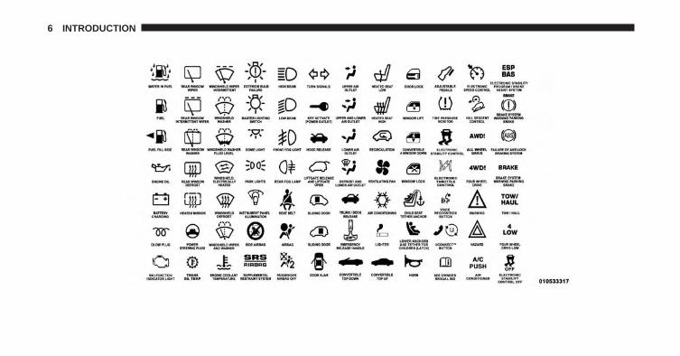
Consult the following table for a description of thesymbols that may be used on your vehicle or throughoutthis Owner’s Manual:
1
INTRODUCTION 5
6 INTRODUCTION
WARNINGS AND CAUTIONS
This Owners Manual contains WARNINGS against op-erating procedures that could result in a collision orbodily injury. It also contains CAUTIONS against proce-dures that could result in damage to your vehicle. If youdo not read this entire Owners Manual, you may missimportant information. Observe all Warnings and Cau-tions.
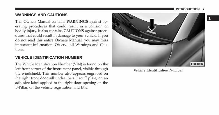
VEHICLE IDENTIFICATION NUMBER
The Vehicle Identification Number (VIN) is found on theleft front corner of the instrument panel, visible throughthe windshield. This number also appears engraved onthe right front door sill under the sill scuff plate, on anadhesive label applied to the right door opening on theB-Pillar, on the vehicle registration and title.
Vehicle Identification Number
1
INTRODUCTION 7

NOTE: It is illegal to remove or alter the VIN.
VEHICLE MODIFICATIONS/ALTERATIONS
WARNING!
Any modifications or alterations to this vehicle couldseriously affect its roadworthiness and safety andmay lead to a collision resulting in serious injury ordeath.
Stamped VIN Location
8 INTRODUCTION

THINGS TO KNOW BEFORE STARTING YOUR VEHICLE
CONTENTS� IMPORTANT VEHICLE INFORMATION . . . . . . .12
▫ High Voltage Battery . . . . . . . . . . . . . . . . . . . .12
� 500e ELECTRIC VEHICLE FEATURES . . . . . . . . .14
▫ Audible Pedestrian Warning System . . . . . . . . .14
▫ Single-Speed Transmission . . . . . . . . . . . . . . . .15
▫ Auto Park. . . . . . . . . . . . . . . . . . . . . . . . . . . .15
▫ E-Park . . . . . . . . . . . . . . . . . . . . . . . . . . . . . .15
▫ Climate Control (HVAC System). . . . . . . . . . . .16
▫ Electric Air Conditioning Compressor . . . . . . . .16
▫ Electric Power Steering . . . . . . . . . . . . . . . . . .16
▫ Smartphone Features . . . . . . . . . . . . . . . . . . . .16
� ELECTRIC SYSTEM OPERATION . . . . . . . . . . . .20
▫ Level 1 Charging (120V — RequiresNEMA 5–15 Outlet) . . . . . . . . . . . . . . . . . . . . .20
▫ Level 2 Charging (240V — Requires A 40 AmpCircuit Breaker Or Greater) . . . . . . . . . . . . . . .20
▫ Charge Times . . . . . . . . . . . . . . . . . . . . . . . . .21
▫ Vehicle Charge Cord . . . . . . . . . . . . . . . . . . . .21
▫ EVSE Operation And Status Information . . . . . .23
2

▫ Charging The High Voltage Battery. . . . . . . . . .25
▫ Vehicle Charge Indicators. . . . . . . . . . . . . . . . .28
� A WORD ABOUT YOUR KEYS . . . . . . . . . . . . .31
▫ Ignition Key Removal . . . . . . . . . . . . . . . . . . .32
▫ Locking Doors With A Key. . . . . . . . . . . . . . . .33
▫ Key-In-Ignition Reminder . . . . . . . . . . . . . . . .34
� SENTRY KEY® . . . . . . . . . . . . . . . . . . . . . . . . .34
▫ Replacement Keys . . . . . . . . . . . . . . . . . . . . .35
▫ General Information . . . . . . . . . . . . . . . . . . . .35
� REMOTE KEYLESS ENTRY (RKE) —IF EQUIPPED . . . . . . . . . . . . . . . . . . . . . . . . . .36
▫ To Unlock The Doors And Liftgate . . . . . . . . . .37
▫ Remote Key Unlock, Driver Door/All Doors1st Press . . . . . . . . . . . . . . . . . . . . . . . . . . . . .37
▫ To Lock The Doors And Liftgate . . . . . . . . . . . .37
▫ Programming Additional Transmitters . . . . . . . .37
▫ Transmitter Battery Replacement . . . . . . . . . . .37
▫ General Information . . . . . . . . . . . . . . . . . . . .39
� DOOR LOCKS . . . . . . . . . . . . . . . . . . . . . . . . .40
▫ Power Door Locks . . . . . . . . . . . . . . . . . . . . .41
� POWER WINDOWS . . . . . . . . . . . . . . . . . . . . .43
▫ Power Window Switches . . . . . . . . . . . . . . . . .43
� LIFTGATE . . . . . . . . . . . . . . . . . . . . . . . . . . . .45
� OCCUPANT RESTRAINTS SYSTEMS . . . . . . . . .46
▫ Seat Belt Systems . . . . . . . . . . . . . . . . . . . . . .47
▫ Supplemental Restraint System (SRS) . . . . . . . .58
▫ Child Restraints . . . . . . . . . . . . . . . . . . . . . . .76
10 THINGS TO KNOW BEFORE STARTING YOUR VEHICLE
▫ Transporting Pets . . . . . . . . . . . . . . . . . . . . . .95
� SAFETY TIPS . . . . . . . . . . . . . . . . . . . . . . . . . .96
▫ Transporting Passengers. . . . . . . . . . . . . . . . . .96
▫ Safety Checks You Should Make Inside TheVehicle . . . . . . . . . . . . . . . . . . . . . . . . . . . . .96
▫ Periodic Safety Checks You Should MakeOutside The Vehicle . . . . . . . . . . . . . . . . . . . .99
2
THINGS TO KNOW BEFORE STARTING YOUR VEHICLE 11

IMPORTANT VEHICLE INFORMATION
Your 500e operates entirely on electricity stored in thehigh voltage battery. Unlike a conventional vehicle orHybrid there is no internal combustion engine. BatteryElectric Vehicles have unique operating characteristicsthat you should become familiar with to ensure you aregetting the optimal performance from your vehicle.
High Voltage Battery
Your vehicle is equipped with a Lithium-ion high voltagebattery that is used to power the electric powertrainsystems and the 12 volt vehicle electrical system.
The high voltage battery is located under the vehicle. Thehigh voltage battery is maintenance free and designed tolast for the life of the vehicle. Lithium-ion batteries provide the following benefits:
• Lithium-ion batteries are much lighter than othertypes of rechargeable batteries of the same size.
1 — High Voltage Cables2 — High Voltage Battery
12 THINGS TO KNOW BEFORE STARTING YOUR VEHICLE

• Lithium-ion batteries hold their charge; they only loseapproximately 3 percent of their charge per month.
• Lithium-ion batteries have no memory, which meansthat you do not have to completely discharge thembefore recharging, as with some other batteries.
• Lithium-ion batteries can be recharged and dischargedthousands of times.
High Voltage Battery Service Disconnect
The high voltage battery service disconnect is locatedunder the rear passenger seat lower cushion. If yourvehicle requires service see your authorized dealer.
WARNING!Never try to remove the high voltage service discon-nect. The high voltage service disconnect is usedwhen your vehicle requires service by a trained
(Continued)
WARNING! (Continued)technician at an authorized dealer. Failure to followthis warning can cause severe burns or electricalshock that may result in serious injury or death.
Disposal of the High Voltage Battery
Your vehicle’s high voltage battery is designed to last thelife of your vehicle. See your authorized dealer forinformation on the disposal of the battery if it shouldrequire replacement.
General Information
The vehicle is also equipped with a Battery ManagementSystem that is designed to:
• Ensure safe operation
• Maximize driving range
• Maximize the life expectancy of the high voltagebattery
2
THINGS TO KNOW BEFORE STARTING YOUR VEHICLE 13
NOTE:
• During vehicle start up and shut down a clicking noisemay be heard from within the vehicle. When theignition key is turned to the on position, the highvoltage battery contactors inside the battery are closedto make the stored electricity inside available forvehicle use. The clicking noise observed is the sound ofthese contactors as they open and close and is normaloperation for your 500e.
• The operating temperature range of the high voltagebattery is -22 °F to 122 °F (-30 °C to 50 °C). If it isattempted to operate the vehicle with the batteryoutside of these temperature extremes it will notfunction.
500e ELECTRIC VEHICLE FEATURES
Understanding the unique characteristics of your 500ewill help ensure maximum performance and the bestdriving range from your vehicle.
Your 500e is equipped with two electrical systems; a 12Volt system that is used to power the conventionalelectrical system and a high voltage system, which isused to drive the wheels through a single-speed trans-mission as well as other high voltage system compo-nents.
Your 500e operates differently then a traditional vehicleor Hybrid vehicle. Here are some of the main differences:
Audible Pedestrian Warning System
Your vehicle is equipped with an Audible PedestrianWarning System. The Audible Pedestrian Warning Sys-tem uses distinct sounds to alert pedestrians that yourvehicle is approaching.
14 THINGS TO KNOW BEFORE STARTING YOUR VEHICLE

The audible warning system uses an in-car sound syn-thesizer with a speaker located in the underhood com-partment. The warning system is automatically activatedwhen selecting DRIVE or REVERSE.
In DRIVE range, the system will remain active until thevehicle reaches a speed of approximately 22 mph(35.5 km/h). At approximately 22 mph (35.5 km/h) thewarning system is deactivated and will automatically beactive when the vehicle returns to approximately 20 mph(32 km/h).
Single-Speed Transmission
Instead of a traditional transmission, your vehicle isequipped with a single-speed transmission to transfer thetorque from the E-Drive motor to the drive wheels. Thistransmission requires no maintenance and is designed tooperate for the life of the vehicle.
Auto Park
Auto Park will automatically place the transmission intoPARK if there is an indication that the driver may leavethe vehicle while still in the DRIVE, NEUTRAL orREVERSE gear. Refer to “Single-Speed Transmission” in“Starting And Operating” for further information.
E-Park
The parking pawl is traditionally located inside an auto-matic transmission and activated when the vehicle isplaced in the PARK position.
E-Park is activated when the driver pushes the PARKbutton. An electric motor activates the parking pawl andlocks the single-speed transmission when the vehicle isplaced into PARK. This will prevent any unwantedmovement of the vehicle.
2
THINGS TO KNOW BEFORE STARTING YOUR VEHICLE 15
NOTE: The engagement of the E-Park can be heard whenthere is no noise in the interior of the vehicle, this is anormal condition.
Climate Control (HVAC System)
Your 500e is equipped with an Automatic TemperatureControl (ATC) HVAC system. This HVAC system utilizesa humidity sensor, cabin sensor, and ambient tempera-ture sensor to choose operation mode and control cabincomfort. These components allow the controller to oper-ate the HVAC system in a very efficient manner tomaximize driving range.
Your 500e also uses an electric air heater to provide heatto the cabin.
Electric Air Conditioning Compressor
Your 500e uses an electric air conditioning compressor.The air conditioning compressor is powered by the highvoltage battery system and is used to cool the vehicle
occupants and the high voltage battery while the vehicleis being driven or when it is being charged.
The high voltage battery may require cooling to keep thevehicle running. The air conditioning compressor willactivate without any input from the occupant.
NOTE: The AC system helps cool the high voltagebattery. If the air conditioning system should requireservice see your authorized dealer as soon as possible.
Electric Power Steering
Your vehicle is equipped with an Electric Power Steering(EPS) system. The power steering system requires nomaintenance and operates without the use of powersteering fluid.
Smartphone Features
With the “FIAT Access” smartphone app, you can moni-tor the state of charge of the high voltage battery orinitiate charging from your phone. You can also turn on
16 THINGS TO KNOW BEFORE STARTING YOUR VEHICLE

your car’s climate control system remotely. The smart-phone app provides the following features:
• Monitor battery charge level
• Display available driving distance
• Check charging status
• Remotely activate vehicle climate control system
• Unlock and lock doors
• Assist with locating your vehicle
• Locate charging stations
• Send a point-of-interest to your vehicle
• Schedule a charge
• View energy consumed
• Notifications for charging and preconditioning events
How do I get the “FIAT Access” smartphone App?
Visit the 500e registration website:
https://www.fiataccess.com/500eSubscribe
Once in the registration website, you will need to enteryour vehicle’s VIN and Connectivity ID. The connectivity
Registration Website
2
THINGS TO KNOW BEFORE STARTING YOUR VEHICLE 17
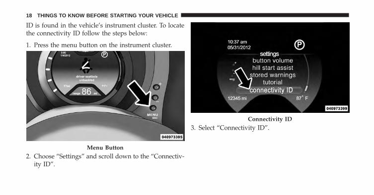
ID is found in the vehicle’s instrument cluster. To locatethe connectivity ID follow the steps below:
1. Press the menu button on the instrument cluster.
2. Choose “Settings” and scroll down to the “Connectiv-ity ID”.
3. Select “Connectivity ID”.
Menu Button
Connectivity ID
18 THINGS TO KNOW BEFORE STARTING YOUR VEHICLE
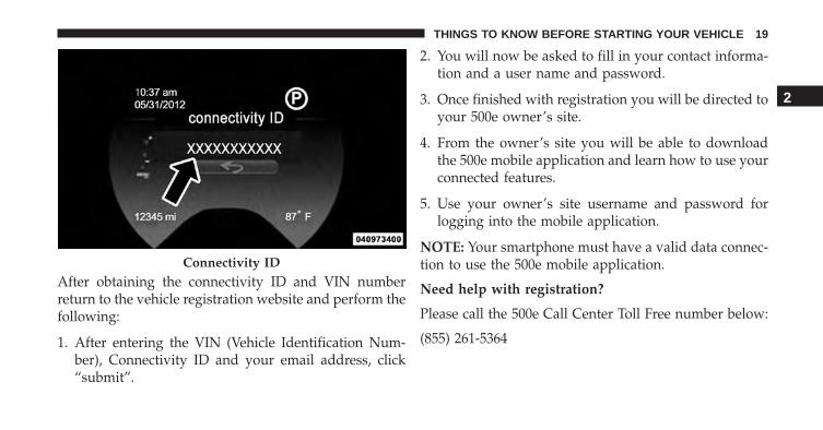
After obtaining the connectivity ID and VIN numberreturn to the vehicle registration website and perform thefollowing:
1. After entering the VIN (Vehicle Identification Num-ber), Connectivity ID and your email address, click“submit”.
2. You will now be asked to fill in your contact informa-tion and a user name and password.
3. Once finished with registration you will be directed toyour 500e owner’s site.
4. From the owner’s site you will be able to downloadthe 500e mobile application and learn how to use yourconnected features.
5. Use your owner’s site username and password forlogging into the mobile application.
NOTE: Your smartphone must have a valid data connec-tion to use the 500e mobile application.
Need help with registration?
Please call the 500e Call Center Toll Free number below:
(855) 261-5364
Connectivity ID
2
THINGS TO KNOW BEFORE STARTING YOUR VEHICLE 19

ELECTRIC SYSTEM OPERATION
Level 1 Charging(120V — Requires NEMA 5–15 Outlet)
Level 1 charging is done by using a conventional 120 VoltAC grounded receptacle along with the NEMA 5–15Electric Vehicle Supply Equipment (EVSE) that comesstandard with your vehicle. Refer to “Vehicle ChargingCord” for further information.
Level 2 Charging(240V — Requires A 40 Amp Circuit Breaker OrGreater)
Level 2 charging is accomplished by using 240V perma-nently mounted EVSEs and is the preferred method forcharging your vehicle.
A Level 2 charging station can be installed at yourresidence. The Level 2 unit and installation service isavailable for purchase at your authorized dealer.
Level 2 Charging Station
20 THINGS TO KNOW BEFORE STARTING YOUR VEHICLE
Charge Times
The following factors determine the time it takes tocharge the high voltage battery:
• The high voltage battery’s current state of charge
• What level EVSE is being used (Level 1 – 120V or Level2 – 240V)
• Ambient temperature
NOTE:
• The charging times are estimates based on a com-pletely discharged high voltage battery.
• Charging times will vary based on the age, condition,state of charge and temperature of the high voltagebattery.
Type of Charge Estimated Charge TimeLevel 1 (120V/15A) Approximately 23 hoursLevel 2 (240V/30A) Approximately 4 hours
Vehicle Charge Cord
Your vehicle comes equipped with a standard AC 120VNEMA 5-15 Electric Vehicle Supply Equipment (EVSE)also referred to as a charge cord.
The EVSE plugs into any standard AC grounded outletand is used to charge the high voltage battery. To accessthe charge cord, lift the rear cargo cover and remove thecharging cord from the storage bin.
2
THINGS TO KNOW BEFORE STARTING YOUR VEHICLE 21
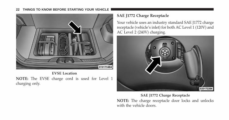
NOTE: The EVSE charge cord is used for Level 1charging only.
SAE J1772 Charge Receptacle
Your vehicle uses an industry standard SAE J1772 chargereceptacle (vehicle’s inlet) for both AC Level 1 (120V) andAC Level 2 (240V) charging.
NOTE: The charge receptacle door locks and unlockswith the vehicle doors.
EVSE Location
SAE J1772 Charge Receptacle
22 THINGS TO KNOW BEFORE STARTING YOUR VEHICLE
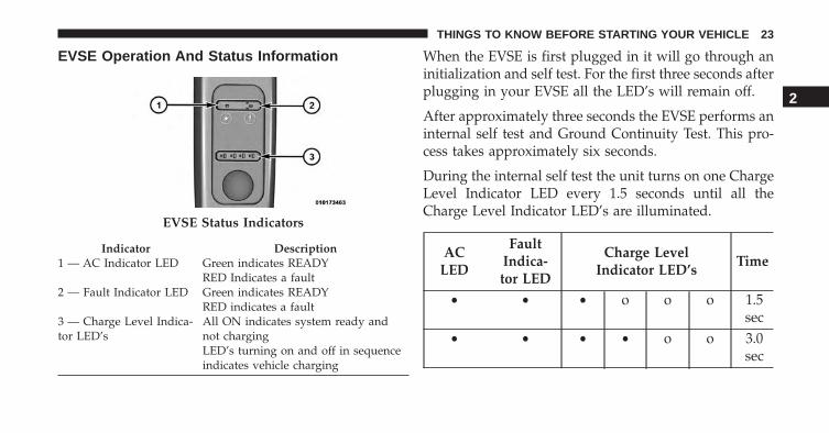
EVSE Operation And Status Information When the EVSE is first plugged in it will go through aninitialization and self test. For the first three seconds afterplugging in your EVSE all the LED’s will remain off.
After approximately three seconds the EVSE performs aninternal self test and Ground Continuity Test. This pro-cess takes approximately six seconds.
During the internal self test the unit turns on one ChargeLevel Indicator LED every 1.5 seconds until all theCharge Level Indicator LED’s are illuminated.
ACLED
FaultIndica-tor LED
Charge LevelIndicator LED’s
Time
• • • o o o 1.5sec
• • • • o o 3.0sec
EVSE Status Indicators
Indicator Description1 — AC Indicator LED Green indicates READY
RED Indicates a fault2 — Fault Indicator LED Green indicates READY
RED indicates a fault3 — Charge Level Indica-tor LED’s
All ON indicates system ready andnot chargingLED’s turning on and off in sequenceindicates vehicle charging
2
THINGS TO KNOW BEFORE STARTING YOUR VEHICLE 23

ACLED
FaultIndica-tor LED
Charge LevelIndicator LED’s
Time
• • • • • o 4.5sec
• • • • • • 6.0sec
If the self test is successful the AC LED, the FaultIndicator LED and the four Charge Level LED’s will turnsolid green.
The EVSE LED’s will be used to indicate the vehicle’sconnection status if no faults are found during the selftest.
AC LEDFault
IndicatorLED
Charge LevelIndicator LED’s
• • • • • •After the EVSE is connected to the vehicle’s charge inletthe EVSE will continue to illuminate all LED’s green.
Once the vehicle begins charging the EVSE Charge levelLED’s will illuminate in order from left to right, then shutoff. This pattern will repeat as long as the EVSE remainsconnected to AC power and the vehicle is activelycharging. Completion of charge will result in illuminat-ing all LED’s green. If the vehicle stops charging, the LEDpattern will stop.
The LED’s are illuminated and turn off at the rate of onechange per second and the battery is charging.
24 THINGS TO KNOW BEFORE STARTING YOUR VEHICLE

ACLED
FaultIndica-tor LED
Charge LevelIndicator LED’s
Time
• • • o o o 1.0sec
• • • • o o 2.0sec
• • • • • o 3.0sec
• • • • • • 4.0sec
Refer to the Level 1 User Manual for any additionalinformation on its use or operation.
Charging The High Voltage Battery
1. Put the vehicle in PARK.
2. Turn the ignition to the OFF position.
3. Remove the Level 1 EVSE from its storage bin bylifting the rear cargo cover.
EVSE Location
2
THINGS TO KNOW BEFORE STARTING YOUR VEHICLE 25
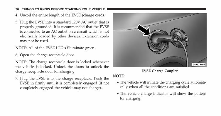
4. Uncoil the entire length of the EVSE (charge cord).
5. Plug the EVSE into a standard 120V AC outlet that isproperly grounded. It is recommended that the EVSEis connected to an AC outlet on a circuit which is notelectrically loaded by other devices. Extension cordsmay not be used.
NOTE: All of the EVSE LED’s illuminate green.
6. Open the charge receptacle door.
NOTE: The charge receptacle door is locked wheneverthe vehicle is locked. Unlock the doors to unlock thecharge receptacle door for charging.
7. Plug the EVSE into the charge receptacle. Push theEVSE in firmly until it is completely engaged (if notcompletely engaged the vehicle may not charge).
NOTE:
• The vehicle will initiate the charging cycle automati-cally when all the conditions are satisfied.
• The vehicle charge indicator will show the patternfor charging.
EVSE Charge Coupler
26 THINGS TO KNOW BEFORE STARTING YOUR VEHICLE
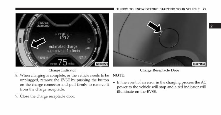
8. When charging is complete, or the vehicle needs to beunplugged, remove the EVSE by pushing the buttonon the charge connector and pull firmly to remove itfrom the charge receptacle.
9. Close the charge receptacle door.
NOTE:
• In the event of an error in the charging process the ACpower to the vehicle will stop and a red indicator willilluminate on the EVSE.
Charge Indicator Charge Receptacle Door
2
THINGS TO KNOW BEFORE STARTING YOUR VEHICLE 27

• Keep the door for the charge receptacle closed whennot in use.
Vehicle Charge Indicators
Instrument Cluster High Voltage Battery Gauge
There is a battery gauge indicator located on the instru-ment cluster. The battery gauge will display, with pro-gressive color indication, the current state of charge forthe high voltage battery; with the percentage valuelocated at the bottom of the gauge.
Charge Low And Limited Power Messages
The state of charge is monitored during normal opera-tion. If the state of charge reaches certain thresholds thefollowing messages will also be displayed on the cluster:
High Voltage Battery Gauge
28 THINGS TO KNOW BEFORE STARTING YOUR VEHICLE

• charge low — displayed at 17% (warning displayed forfive seconds).
• charge low — displayed at 11% (remains on until thecondition changes).
• charge low limited power mode — turtle displayed at5% and remains on.
• charge low limited power mode — turtle flashes at 0%until condition changes.
NOTE: The limited power mode can also be activated ifthe high voltage battery temperature is too high or toolow.
Charge Low Message
Charge Low Limited Power Mode
2
THINGS TO KNOW BEFORE STARTING YOUR VEHICLE 29

NOTE: At 0% state of charge or below the followingfeatures will be disabled if in use:
• Heated Seats
• Electronic Speed Control
• Climate Controls
Instrument Panel State Of Charge Indicator
In addition to the battery gauge your vehicle is equippedwith a visual state of charge indicator. The state of chargeindicator is made up of five lights that are mounted to thecenter of the instrument panel.
The state of charge indicator represents the current stateof charge for the high voltage battery. The state of chargeindicator lights quickly to identify the battery state ofcharge while the vehicle is being charged. Each lightrepresents the percent of charge that the battery iscurrently at.
State Of Charge Indicator
30 THINGS TO KNOW BEFORE STARTING YOUR VEHICLE
NOTE: In the event of an error in the charging processthe outer two lights will blink.
Number Of IndicatorLights Illuminated
Percent Of BatteryCharge
1 Light 0 – 20%2 Lights 21 – 40%3 Lights 41 – 60%4 Lights 61 – 80%5 Lights 81 – 100%
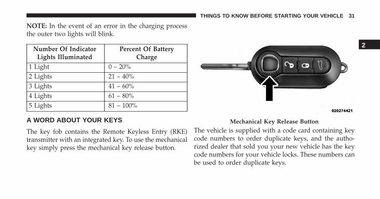
A WORD ABOUT YOUR KEYS
The key fob contains the Remote Keyless Entry (RKE)transmitter with an integrated key. To use the mechanicalkey simply press the mechanical key release button.
The vehicle is supplied with a code card containing keycode numbers to order duplicate keys, and the autho-rized dealer that sold you your new vehicle has the keycode numbers for your vehicle locks. These numbers canbe used to order duplicate keys.
Mechanical Key Release Button
2
THINGS TO KNOW BEFORE STARTING YOUR VEHICLE 31

Ignition Key Removal
1. Place the transmission in PARK.
2. Rotate the key to the OFF/LOCK position.
3. Remove the key from the ignition switch lock cylinder.
Ignition Switch Positions
1 — STOP (OFF/LOCK) 3 — AVV (START)2 — MAR (ACC/ON/RUN)
32 THINGS TO KNOW BEFORE STARTING YOUR VEHICLE
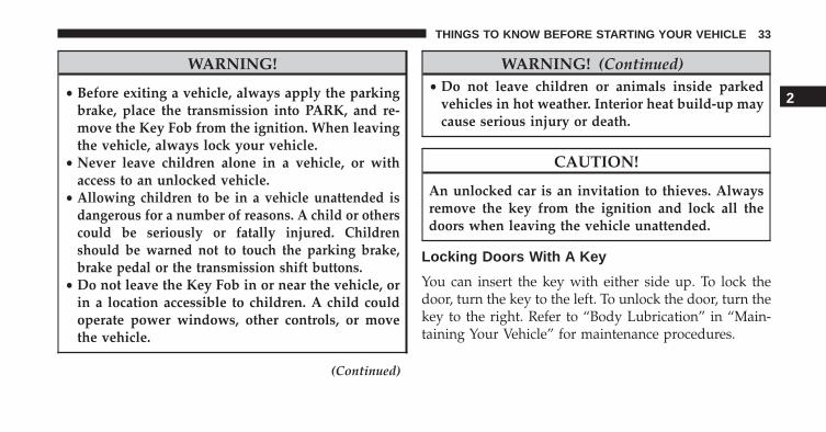
WARNING!
• Before exiting a vehicle, always apply the parkingbrake, place the transmission into PARK, and re-move the Key Fob from the ignition. When leavingthe vehicle, always lock your vehicle.
• Never leave children alone in a vehicle, or withaccess to an unlocked vehicle.
• Allowing children to be in a vehicle unattended isdangerous for a number of reasons. A child or otherscould be seriously or fatally injured. Childrenshould be warned not to touch the parking brake,brake pedal or the transmission shift buttons.
• Do not leave the Key Fob in or near the vehicle, orin a location accessible to children. A child couldoperate power windows, other controls, or movethe vehicle.
(Continued)
WARNING! (Continued)• Do not leave children or animals inside parked
vehicles in hot weather. Interior heat build-up maycause serious injury or death.
CAUTION!
An unlocked car is an invitation to thieves. Alwaysremove the key from the ignition and lock all thedoors when leaving the vehicle unattended.
Locking Doors With A Key
You can insert the key with either side up. To lock thedoor, turn the key to the left. To unlock the door, turn thekey to the right. Refer to “Body Lubrication” in “Main-taining Your Vehicle” for maintenance procedures.
2
THINGS TO KNOW BEFORE STARTING YOUR VEHICLE 33

Key-In-Ignition Reminder
Opening the driver’s door when the key is in the ignitionand the ignition switch position is OFF/LOCK, sounds asignal to remove the key.
SENTRY KEY®
The Sentry Key® Immobilizer System prevents unau-thorized vehicle operation by disabling the starting sys-tem. The system does not need to be armed or activated.Operation is automatic, regardless of whether the vehicleis locked or unlocked.
The system uses ignition keys which have an embeddedelectronic chip (transponder) to prevent unauthorizedvehicle operation. Therefore, only keys that are pro-grammed to the vehicle can be used to start and operatethe vehicle.
NOTE: A key which has not been programmed is alsoconsidered an invalid key, even if it is cut to fit theignition switch lock cylinder for that vehicle.
If the Vehicle Security Light is on after the key is turnedto the ON/RUN position, it indicates that there is aproblem with the electronics.
CAUTION!
• Always remove the Sentry Key® from the vehicleand lock all doors when leaving the vehicle unat-tended.
• The Sentry Key® Immobilizer system is not com-patible with some aftermarket remote starting sys-tems. Use of these systems may result in vehiclestarting problems and loss of security protection.
All of the keys provided with your new vehicle havebeen programmed to the vehicle electronics.
34 THINGS TO KNOW BEFORE STARTING YOUR VEHICLE
Replacement Keys
NOTE: Only keys that have been programmed to thevehicle electronics can be used to start the vehicle. Oncea Sentry Key® has been programmed to a vehicle, itcannot be programmed to any other vehicle.
At the time of purchase, the original owner is providedwith a four-digit Personal Identification Number (PIN).This PIN is required for authorized dealer replacement ofkeys. Duplication of keys may be performed at anauthorized dealer. This procedure consists of program-ming a blank key to the vehicle electronics. A blank keyis one which has never been programmed.
NOTE: When having the Sentry Key® ImmobilizerSystem serviced, bring all vehicle keys with you to anauthorized dealer.
General Information
The Sentry Key® system complies with FCC rules part 15and with RSS-210 of Industry Canada. Operation issubject to the following conditions:
• This device may not cause harmful interference.
• This device must accept any interference that may bereceived, including interference that may cause unde-sired operation.
NOTE: Changes or modifications not expressly approvedby the party responsible for compliance could void theuser’s authority to operate the equipment.
2
THINGS TO KNOW BEFORE STARTING YOUR VEHICLE 35

REMOTE KEYLESS ENTRY (RKE) — IFEQUIPPED
This system allows you to lock or unlock the doors andliftgate from distances up to approximately 66 ft (20 m)using a hand-held Remote Keyless Entry (RKE) transmit-ter. The RKE transmitter does not need to be pointed atthe vehicle to activate the system.
NOTE: The line of transmission must not be blockedwith metal objects.
Remote Keyless Entry Transmitter With Mechanical KeyRelease Button
36 THINGS TO KNOW BEFORE STARTING YOUR VEHICLE

To Unlock The Doors And Liftgate
Press and release the UNLOCK button on the RKEtransmitter once to unlock the driver’s door or twice,within five seconds, to unlock all doors and the liftgate.The turn signal lights will flash to acknowledge theunlock signal. The illuminated entry system will alsoturn on.
Remote Key Unlock, Driver Door/All Doors 1stPress
This feature lets you program the system to unlock eitherthe driver’s door or all doors on the first press of theUNLOCK button on the RKE transmitter. To change thecurrent setting, refer to “Personal Settings (Customer-Programmable Features)” in “Understanding Your In-strument Panel” for further information.
To Lock The Doors And Liftgate
Press and release the LOCK button on the RKE transmit-ter to lock all doors and the liftgate. The turn signal lightswill flash and the horn will chirp to acknowledge thesignal.
Programming Additional Transmitters
Refer to Sentry Key® “Customer Key Programming”.
If you do not have a programmed RKE transmitter,contact your authorized dealer for details.
Transmitter Battery Replacement
NOTE: Perchlorate Material – special handling may ap-ply. See www.dtsc.ca.gov/hazardouswaste/perchlorate
The recommended replacement battery is CR2032.
1. Press the mechanical key release button and releasethe mechanical key to access the battery case screwlocated on the side of the Key Fob.
2
THINGS TO KNOW BEFORE STARTING YOUR VEHICLE 37
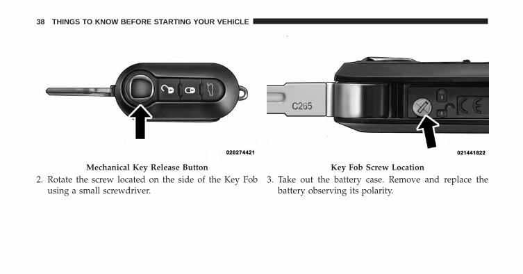
2. Rotate the screw located on the side of the Key Fobusing a small screwdriver.
3. Take out the battery case. Remove and replace thebattery observing its polarity.
Mechanical Key Release Button Key Fob Screw Location
38 THINGS TO KNOW BEFORE STARTING YOUR VEHICLE

4. Refit the battery case inside the Key Fob and turn thescrew to lock it into place.
General Information
This device complies with Part 15 of the FCC rules andRSS 210 of Industry Canada. Operation is subject to thefollowing conditions:
• This device may not cause harmful interference.
• This device must accept any interference received,including interference that may cause undesired op-eration.
NOTE: Changes or modifications not expressly approvedby the party responsible for compliance could void theuser’s authority to operate the equipment.
If your RKE transmitter fails to operate from a normaldistance, check for these two conditions:
1. A weak battery in the transmitter. The expected life ofthe battery is a minimum of three years.
Battery Case Removed
2
THINGS TO KNOW BEFORE STARTING YOUR VEHICLE 39

2. Closeness to a radio transmitter such as a radio stationtower, airport transmitter, and some mobile or CBradios.
DOOR LOCKS
The door locks can be manually locked or unlocked frominside the vehicle by using the door handle. If the doorhandle is pushed a red lock indicator will show on thedoor handle (indicating locked) when the door is open orclosed, the door will lock.
NOTE: To prevent the key from being locked in thevehicle, the doors will automatically unlock if the driv-er’s door handle is pushed when the key is in the ignitionand either front door is open. A chime will sound as areminder to remove the key.
Door Lock Handle
40 THINGS TO KNOW BEFORE STARTING YOUR VEHICLE

WARNING!
• Do not leave children or animals inside parkedvehicles in hot weather. Interior heat build-up maycause serious injury or death.
• For personal security and safety in the event of ancollision, lock the vehicle doors as you drive aswell as when you park and leave the vehicle.
• Before exiting a vehicle, always apply the parkingbrake, place the transmission into PARK, and re-move the Key Fob from the ignition. When leavingthe vehicle, always lock your vehicle.
• Never leave children alone in a vehicle, or withaccess to an unlocked vehicle.
• Allowing children to be in a vehicle unattended isdangerous for a number of reasons. A child orothers could be seriously or fatally injured. Chil-dren should be warned not to touch the parking
(Continued)
WARNING! (Continued)brake, brake pedal or the transmission push-buttons.
• Do not leave the Key Fob in or near the vehicle, orin a location accessible to children. A child couldoperate power windows, other controls, or movethe vehicle.
CAUTION!
An unlocked vehicle is an invitation to thieves.Always remove the key from the ignition and lock allof the doors when leaving the vehicle unattended.
Power Door Locks
A power door lock switch is incorporated into the driverdoor handle. Push or pull the handle to lock or unlock thedoors and liftgate. If the driver’s door handle is pushed
2
THINGS TO KNOW BEFORE STARTING YOUR VEHICLE 41

a red lock indicator will show on the driver’s door handle(indicating locked) when the door is closed, the door willlock.
NOTE: To prevent the key from being locked in thevehicle, the doors will automatically unlock if the driv-er’s door handle is pushed when the key is in theignition.
Driver’s Power Door Lock Handle
42 THINGS TO KNOW BEFORE STARTING YOUR VEHICLE

Autoclose
When enabled, the door locks will lock automaticallywhen the vehicles speed exceeds 15 mph (24 km/h).
To change the setting proceed as follows:
1. Briefly press the MENU button to enter the MENUscreen.
2. Press the UP or DOWN button to highlight“Autoclose”. Press the MENU button, use the UP
or DOWN buttons to turn setting ON or OFF
3. Briefly press the MENU button to go back to the menuscreen, or press and hold the MENU button (approxi-mately one second) to go back to the main screenwithout storing the settings.
NOTE: Use the Automatic Door Locks feature in accor-dance with local laws.
Refer to “Electronic Vehicle Information Center (EVIC)”in “Understanding Your Vehicle” for further information.
POWER WINDOWS
Power Window Switches
There are single window controls located on the shifterbezel, below the climate controls, which operate thedriver and passenger door windows. The window con-trols will operate when the ignition switch is in theON/RUN position.
WARNING!
Never leave children unattended in a vehicle, and donot let children play with power windows. Do notleave the Key Fob in or near the vehicle, or in a
(Continued)
2
THINGS TO KNOW BEFORE STARTING YOUR VEHICLE 43
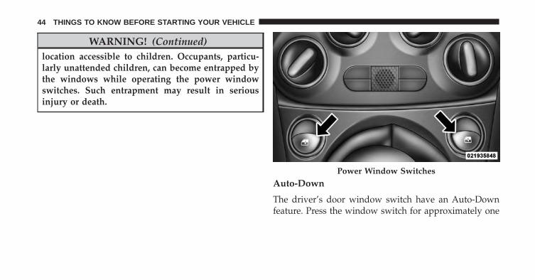
WARNING! (Continued)location accessible to children. Occupants, particu-larly unattended children, can become entrapped bythe windows while operating the power windowswitches. Such entrapment may result in seriousinjury or death.
Auto-Down
The driver’s door window switch have an Auto-Downfeature. Press the window switch for approximately one
Power Window Switches
44 THINGS TO KNOW BEFORE STARTING YOUR VEHICLE
second, release, and the window will go down automati-cally. To cancel the Auto-Down movement, operate theswitch in either the up or down direction and release theswitch.
Wind Buffeting
Wind buffeting can be described as the perception ofpressure on the ears or a helicopter-type sound in theears. Your vehicle may exhibit wind buffeting with thewindows down, or the sunroof (if equipped) in certainopen or partially open positions. This is a normal occur-rence and can be minimized. If the buffeting occurs withthe sunroof open, adjust the sunroof opening to minimizethe buffeting or open any window.
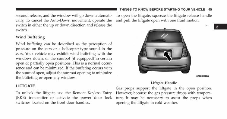
LIFTGATE
To unlock the liftgate, use the Remote Keyless Entry(RKE) transmitter or activate the power door lockswitches located on the front door handles.
To open the liftgate, squeeze the liftgate release handleand pull the liftgate open with one fluid motion.
Gas props support the liftgate in the open position.However, because the gas pressure drops with tempera-ture, it may be necessary to assist the props whenopening the liftgate in cold weather.
Liftgate Handle
2
THINGS TO KNOW BEFORE STARTING YOUR VEHICLE 45

OCCUPANT RESTRAINTS SYSTEMS
Some of the most important safety features in yourvehicle are the restraint systems:
• Seat Belt Systems
• SRS Air Bags
• Child Restraints
Important Safety Precautions:
Please pay close attention to the information in thissection. It tells you how to use your restraint systemproperly, to keep you and your passengers as safe aspossible.
Here are some simple steps you can take to minimize therisk of harm from a deploying air bag:
1. Children 12 years old and under should always ridebuckled up in a vehicle with a rear seat.
2. If a child from 2 to 12 years old (not in a rear-facingchild restraint) must ride in the front passenger seat,move the seat as far back as possible and use theproper child restraint. (Refer to “Child Restraints.”)
3. If you will be carrying children too small for adult-sized seat belts, the seat belts or the Lower Anchorsand Tethers for CHildren (LATCH) feature can be usedto attach child restraints. For more information onLATCH, refer to Lower Anchors and Tethers forCHildren (LATCH).
4. Children that are not big enough to wear the vehicleseat belt properly (Refer to “Child Restraints”) shouldbe secured in the rear seat in child restraints orbelt-positioning booster seats. Older children who donot use child restraints or belt-positioning boosterseats should ride properly buckled up in the rear seat.
5. Never allow children to slide the shoulder belt behindthem or under their arm.
46 THINGS TO KNOW BEFORE STARTING YOUR VEHICLE
6. You should read the instructions provided with yourchild restraint to make sure that you are using itproperly.
7. All occupants should always wear their lap andshoulder belts properly.
8. The driver and front passenger seats should be movedback as far as practical to allow the Advanced FrontAir Bags room to inflate.
9. Do not lean against the door or window. If yourvehicle has side air bags, and deployment occurs, theside air bags will inflate forcefully into the spacebetween you and the door and you could be injured.
10. If the air bag system in this vehicle needs to bemodified to accommodate a disabled person, contactthe Customer Center. Phone numbers are providedunder �If You Need Assistance.�
WARNING!
• Never place a rear-facing child restraint in front ofan air bag. A deploying Passenger Advanced FrontAir Bag can cause death or serious injury to a child12 years or younger, including a child in a rear-facing child restraint.
• Only use a rear-facing child restraint in a vehiclewith a rear seat.
Seat Belt Systems
Buckle up even though you are an excellent driver, evenon short trips. Someone on the road may be a poor driverand could cause a collision that includes you. This canhappen far away from home or on your own street.
Research has shown that seat belts save lives, and theycan reduce the seriousness of injuries in a collision. Someof the worst injuries happen when people are thrownfrom the vehicle. Seat belts reduce the possibility of
2
THINGS TO KNOW BEFORE STARTING YOUR VEHICLE 47
ejection and the risk of injury caused by striking theinside of the vehicle. Everyone in a motor vehicle shouldbe belted at all times.
Enhanced Seat Belt Use Reminder System(BeltAlert®)
BeltAlert® is a feature intended to remind thedriver and outboard front passenger (if equipped withoutboard front passenger BeltAlert®) to buckle theirseat belts. The feature is active whenever the ignitionswitch is in the START or ON/RUN position. If thedriver or outboard front seat passenger is unbelted,the Seat Belt Reminder Light will turn on and remainon until both outboard front seat belts are buckled.
The BeltAlert® warning sequence begins after the vehiclespeed is over 5 mph (8 km/h) by blinking the Seat BeltReminder Light and sounding an intermittent chime.Once the sequence starts, it will continue for the entireduration or until the respective seat belts are buckled.
After the sequence completes, the Seat Belt ReminderLight remains illuminated until the respective seat beltsare buckled. The driver should instruct all other occu-pants to buckle their seat belts. If an outboard front seatbelt is unbuckled while traveling at speeds greater than5 mph (8 km/h), BeltAlert® will provide both audio andvisual notification.
The outboard front passenger seat BeltAlert® is notactive when the outboard front passenger seat is unoc-cupied. BeltAlert® may be triggered when an animal orheavy object is on the outboard front passenger seat orwhen the seat is folded flat (if equipped). It is recom-mended that pets be restrained in the rear seat (ifequipped) in pet harnesses or pet carriers that are se-cured by seat belts, and cargo is properly stowed.
BeltAlert® can be activated or deactivated by your au-thorized dealer. FCA US LLC does not recommenddeactivating BeltAlert®.
48 THINGS TO KNOW BEFORE STARTING YOUR VEHICLE
NOTE: If BeltAlert® has been deactivated, the Seat BeltReminder Light will continue to illuminate while thedriver’s or outboard front passenger’s (if equipped withBeltAlert®) seat belt remains unbuckled.
Lap/Shoulder Belts
All seating positions in your vehicle are equipped withlap/shoulder belts.
The seat belt webbing retractor will lock only during verysudden stops or collisions. This feature allows the shoul-der part of the seat belt to move freely with you undernormal conditions. However, in a collision the seat beltwill lock and reduce your risk of striking the inside of thevehicle or being thrown out of the vehicle.
This seat belt system has a retractor assembly that isdesigned to release webbing in a controlled manner. Thisfeature is designed to help reduce the seat belt forceacting on the occupant’s chest.
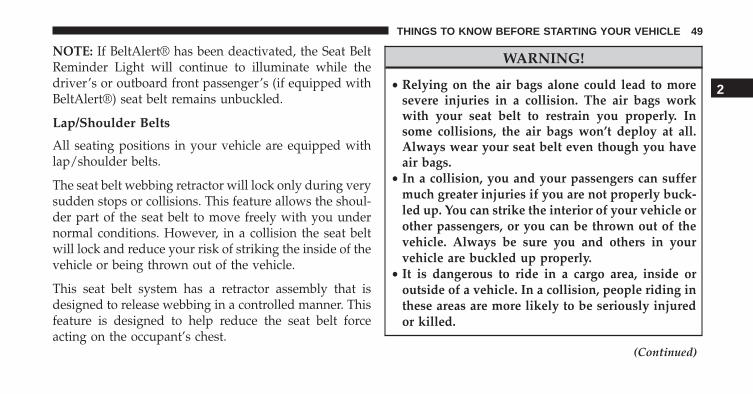
WARNING!
• Relying on the air bags alone could lead to moresevere injuries in a collision. The air bags workwith your seat belt to restrain you properly. Insome collisions, the air bags won’t deploy at all.Always wear your seat belt even though you haveair bags.
• In a collision, you and your passengers can suffermuch greater injuries if you are not properly buck-led up. You can strike the interior of your vehicle orother passengers, or you can be thrown out of thevehicle. Always be sure you and others in yourvehicle are buckled up properly.
• It is dangerous to ride in a cargo area, inside oroutside of a vehicle. In a collision, people riding inthese areas are more likely to be seriously injuredor killed.
(Continued)
2
THINGS TO KNOW BEFORE STARTING YOUR VEHICLE 49

WARNING! (Continued)• Do not allow people to ride in any area of your
vehicle that is not equipped with seats and seatbelts.
• Be sure everyone in your vehicle is in a seat andusing a seat belt properly.
• Wearing your seat belt incorrectly could make yourinjuries in a collision much worse. You mightsuffer internal injuries, or you could even slide outof the seat belt. Follow these instructions to wearyour seat belt safely and to keep your passengerssafe, too.
• Two people should never be belted into a singleseat belt. People belted together can crash into oneanother in a collision, hurting one another badly.Never use a lap/shoulder belt or a lap belt for morethan one person, no matter what their size.
(Continued)
WARNING! (Continued)• A lap belt worn too high can increase the risk of
injury in a collision. The seat belt forces won’t be atthe strong hip and pelvic bones, but across yourabdomen. Always wear the lap part of your seatbelt as low as possible and keep it snug.
• A twisted seat belt may not protect you properly. Ina collision, it could even cut into you. Be sure theseat belt is flat against your body, without twists. Ifyou can’t straighten a seat belt in your vehicle, takeit to your authorized dealer immediately and haveit fixed.
• A seat belt that is buckled into the wrong bucklewill not protect you properly. The lap portion couldride too high on your body, possibly causing inter-nal injuries. Always buckle your seat belt into thebuckle nearest you.
(Continued)
50 THINGS TO KNOW BEFORE STARTING YOUR VEHICLE

WARNING! (Continued)• A seat belt that is too loose will not protect you
properly. In a sudden stop, you could move too farforward, increasing the possibility of injury. Wearyour seat belt snugly.
• A seat belt that is worn under your arm is danger-ous. Your body could strike the inside surfaces ofthe vehicle in a collision, increasing head and neckinjury. A seat belt worn under the arm can causeinternal injuries. Ribs aren’t as strong as shoulderbones. Wear the seat belt over your shoulder so thatyour strongest bones will take the force in a colli-sion.
• A shoulder belt placed behind you will not protectyou from injury during a collision. You are morelikely to hit your head in a collision if you do not
(Continued)
WARNING! (Continued)wear your shoulder belt. The lap and shoulder beltare meant to be used together.
• A frayed or torn seat belt could rip apart in acollision and leave you with no protection. Inspectthe seat belt system periodically, checking for cuts,frays, or loose parts. Damaged parts must be re-placed immediately. Do not disassemble or modifythe seat belt system. Seat belt assemblies must bereplaced after a collision.
Lap/Shoulder Belt Operating Instructions
1. Enter the vehicle and close the door. Sit back andadjust the seat.
2. The seat belt latch plate is above the back of the frontseat, and next to your arm in the rear seat (for vehiclesequipped with a rear seat). Grasp the latch plate and
2
THINGS TO KNOW BEFORE STARTING YOUR VEHICLE 51

pull out the belt. Slide the latch plate up the webbingas far as necessary to allow the belt to go around yourlap.
3. When the belt is long enough to fit, insert the latchplate into the buckle until you hear a “click.”
4. Position the lap belt snug and lies low across yourhips, below your abdomen. To remove slack in the lapbelt portion, pull up on the shoulder belt. To loosenthe lap belt if it is too tight, tilt the latch plate and pullon the lap belt. A snug belt reduces the risk of slidingunder the belt in a collision.
Pulling Out The Latch Plate
Inserting Latch Plate Into Buckle
52 THINGS TO KNOW BEFORE STARTING YOUR VEHICLE
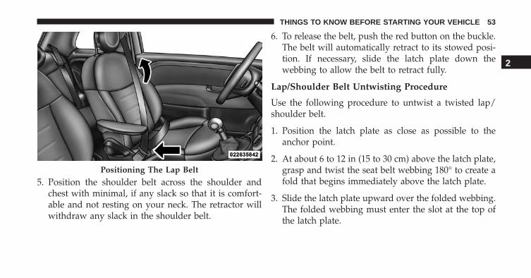
5. Position the shoulder belt across the shoulder andchest with minimal, if any slack so that it is comfort-able and not resting on your neck. The retractor willwithdraw any slack in the shoulder belt.
6. To release the belt, push the red button on the buckle.The belt will automatically retract to its stowed posi-tion. If necessary, slide the latch plate down thewebbing to allow the belt to retract fully.
Lap/Shoulder Belt Untwisting Procedure
Use the following procedure to untwist a twisted lap/shoulder belt.
1. Position the latch plate as close as possible to theanchor point.
2. At about 6 to 12 in (15 to 30 cm) above the latch plate,grasp and twist the seat belt webbing 180° to create afold that begins immediately above the latch plate.
3. Slide the latch plate upward over the folded webbing.The folded webbing must enter the slot at the top ofthe latch plate.
Positioning The Lap Belt
2
THINGS TO KNOW BEFORE STARTING YOUR VEHICLE 53
4. Continue to slide the latch plate up until it clears thefolded webbing and the seat belt is no longer twisted.
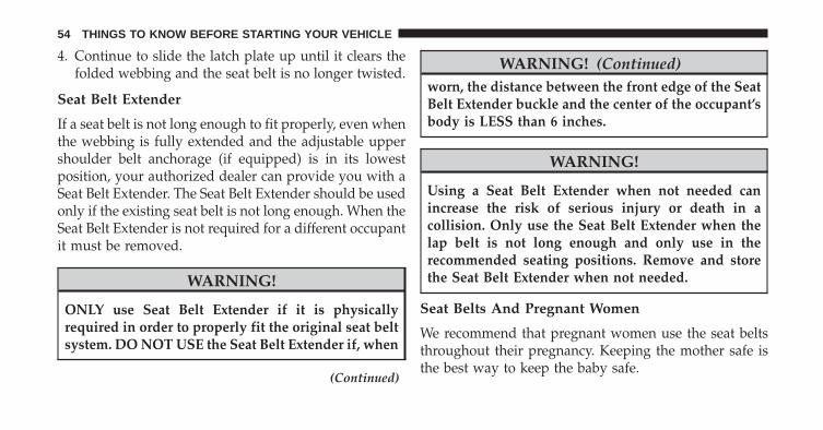
Seat Belt Extender
If a seat belt is not long enough to fit properly, even whenthe webbing is fully extended and the adjustable uppershoulder belt anchorage (if equipped) is in its lowestposition, your authorized dealer can provide you with aSeat Belt Extender. The Seat Belt Extender should be usedonly if the existing seat belt is not long enough. When theSeat Belt Extender is not required for a different occupantit must be removed.
WARNING!
ONLY use Seat Belt Extender if it is physicallyrequired in order to properly fit the original seat beltsystem. DO NOT USE the Seat Belt Extender if, when
(Continued)
WARNING! (Continued)worn, the distance between the front edge of the SeatBelt Extender buckle and the center of the occupant’sbody is LESS than 6 inches.
WARNING!
Using a Seat Belt Extender when not needed canincrease the risk of serious injury or death in acollision. Only use the Seat Belt Extender when thelap belt is not long enough and only use in therecommended seating positions. Remove and storethe Seat Belt Extender when not needed.
Seat Belts And Pregnant Women
We recommend that pregnant women use the seat beltsthroughout their pregnancy. Keeping the mother safe isthe best way to keep the baby safe.
54 THINGS TO KNOW BEFORE STARTING YOUR VEHICLE
Pregnant women should wear the lap part of the seat beltacross the thighs and as snug across the hips as possible.Keep the seat belt low so that it does not come across theabdomen. That way the strong bones of the hips will takethe force if there is a collision.
Seat Belt Pretensioner
The front seat belt system is equipped with pretensioningdevices that are designed to remove slack from the seatbelt in the event of a collision. These devices mayimprove the performance of the seat belt by removingslack from the seat belt early in a collision. Pretensionerswork for all size occupants, including those in childrestraints.
NOTE: These devices are not a substitute for proper seatbelt placement by the occupant. The seat belt still must beworn snugly and positioned properly.
The pretensioners are triggered by the Occupant Re-straint Controller (ORC). Like the air bags, the preten-sioners are single use items. A deployed pretensioner ora deployed air bag must be replaced immediately.
Energy Management Feature
This vehicle has a seat belt system with an EnergyManagement feature in the front seating positions thatmay help further reduce the risk of injury in the event ofa collision. This seat belt system has a retractor assemblythat is designed to release webbing in a controlledmanner.
Switchable Automatic Locking Retractor (ALR) —If Equipped
The seat belts in the passenger seating positions may beequipped with a switchable Automatic Locking Retractor(ALR) which is used to secure a child restraint system.For additional information, refer to “Installing ChildRestraints Using The Vehicle Seat Belt” under the “Child
2
THINGS TO KNOW BEFORE STARTING YOUR VEHICLE 55
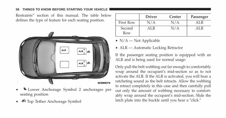
Restraints” section of this manual. The table belowdefines the type of feature for each seating position.
• Lower Anchorage Symbol 2 anchorages perseating position
• Top Tether Anchorage Symbol
Driver Center PassengerFirst Row N/A N/A ALR
SecondRow
ALR N/A ALR
• N/A — Not Applicable
• ALR — Automatic Locking Retractor
If the passenger seating position is equipped with anALR and is being used for normal usage:
Only pull the belt webbing out far enough to comfortablywrap around the occupant’s mid-section so as to notactivate the ALR. If the ALR is activated, you will hear aratcheting sound as the belt retracts. Allow the webbingto retract completely in this case and then carefully pullout only the amount of webbing necessary to comfort-ably wrap around the occupant’s mid-section. Slide thelatch plate into the buckle until you hear a �click.�
56 THINGS TO KNOW BEFORE STARTING YOUR VEHICLE

In Automatic Locking Mode, the shoulder belt is auto-matically pre- locked. The belt will still retract to removeany slack in the shoulder belt. The Automatic LockingMode is avail- able on all passenger-seating positionswith a combination lap/shoulder belt. Use the AutomaticLocking Mode anytime a child safety seat is installed in aseating position that has a belt with this feature. Children12 years old and under should always be properlyrestrained in a vehicle with a rear seat.
WARNING!
• Never place a rear-facing child restraint in front ofan air bag. A deploying Passenger Advanced FrontAir Bag can cause death or serious injury to a child12 years or younger, including a child in a rear-facing child restraint.
• Only use a rear-facing child restraint in a vehiclewith a rear seat.
How To Engage The Automatic Locking Mode
1. Buckle the combination lap and shoulder belt.
2. Grasp the shoulder portion and pull downward untilthe entire seat belt is extracted.
3. Allow the seat belt to retract. As the seat belt retracts,you will hear a clicking sound. This indicates the seatbelt is now in the Automatic Locking Mode.
How To Disengage The Automatic Locking Mode
Unbuckle the combination lap/shoulder belt and allow itto retract completely to disengage the Automatic LockingMode and activate the vehicle sensitive (emergency)locking mode.
2
THINGS TO KNOW BEFORE STARTING YOUR VEHICLE 57
WARNING!
• The seat belt assembly must be replaced if theswitchable Automatic Locking Retractor (ALR) fea-ture or any other seat belt function is not workingproperly when checked according to the proce-dures in the Service Manual.
• Failure to replace the seat belt assembly couldincrease the risk of injury in collisions.
• Do not use the Automatic Locking Mode to restrainoccupants who are wearing the seat belt or childrenwho are using booster seats. The locked mode isonly used to install rear-facing or forward-facingchild restraints that have a harness for restrainingthe child.
Supplemental Restraint System (SRS)
Air Bag System Components
Your vehicle may be equipped with the following air bagsystem components:
• Occupant Restraint Controller (ORC)
• Air Bag Warning Light
• Steering Wheel and Column
• Instrument Panel
• Knee Impact Bolsters
• Advanced Front Air Bags
• Supplemental Side Air Bags
• Supplemental Knee Air Bag
• Front and Side Impact Sensors
58 THINGS TO KNOW BEFORE STARTING YOUR VEHICLE

• Seat Belt Pretenioners
• Seat Belt Buckle Switch
• Seat Track Position Sensors
Advanced Front Air Bags
This vehicle has Advanced Front Air Bags for both thedriver and front passenger as a supplement to the seatbelt restraint systems. The driver’s Advanced Front AirBag is mounted in the center of the steering wheel. Thepassenger’s Advanced Front Air Bag is mounted in theinstrument panel, above the glove compartment. Thewords SRS AIRBAG are embossed on the air bag covers. Advanced Front Air Bag And Knee Bolster Locations
1 — Driver And Passenger Advanced Front Air Bags2— Supplemental Driver Side Knee Air Bag/Knee Bolster3 — Knee Bolster
2
THINGS TO KNOW BEFORE STARTING YOUR VEHICLE 59

WARNING!
• Being too close to the steering wheel or instrumentpanel during Advanced Front Air Bag deploymentcould cause serious injury, including death. Airbags need room to inflate. Sit back, comfortablyextending your arms to reach the steering wheel orinstrument panel.
• Never place a rear-facing child restraint in front ofan air bag. A deploying Passenger Advanced FrontAir Bag can cause death or serious injury to a child12 years or younger, including a child in a rear-facing child restraint.
• Only use a rear-facing child restraint in a vehiclewith a rear seat.
Advanced Front Air Bag Features
The Advanced Front Air Bag system has multistagedriver and front passenger air bags. This system provides
output appropriate to the severity and type of collision asdetermined by the Occupant Restraint Controller (ORC),which may receive information from the front impactsensors or other system components.
The first stage inflator is triggered immediately during animpact that requires air bag deployment. A low energyoutput is used in less severe collisions. A higher energyoutput is used for more severe collisions.
This vehicle may be equipped with driver and/or frontpassenger seat track position sensors that may adjust theinflation rate of the Advanced Front Air Bags based uponseat position.
This vehicle may be equipped with a driver and/or frontpassenger seat belt buckle switch that detects whetherthe driver or front passenger seat belt is fastened. Theseat belt buckle switch may adjust the inflation rate of theAdvanced Front Air Bags.
60 THINGS TO KNOW BEFORE STARTING YOUR VEHICLE

WARNING!
• No objects should be placed over or near the airbag on the instrument panel or steering wheel,because any such objects could cause harm if thevehicle is in a collision severe enough to cause theair bags to inflate.
• Do not put anything on or around the air bagcovers or attempt to open them manually. You maydamage the air bags and you could be injuredbecause the air bags may no longer be functional.The protective covers for the air bag cushions aredesigned to open only when the air bags areinflating.
• Relying on the air bags alone could lead to moresevere injuries in a collision. The air bags workwith your seat belt to restrain you properly. In
(Continued)
WARNING! (Continued)some collisions, air bags won’t deploy at all. Al-ways wear your seat belts even though you have airbags.
Advanced Front Air Bag Operation
Advanced Front Air Bags are designed to provide addi-tional protection by supplementing the seat belts. Ad-vanced Front Air Bags are not expected to reduce the riskof injury in rear, side, or rollover collisions. The Ad-vanced Front Air Bags will not deploy in all frontalcollisions, including some that may produce substantialvehicle damage — for example, some pole collisions,truck underrides, and angle offset collisions.
On the other hand, depending on the type and location ofimpact, Advanced Front Air Bags may deploy in crasheswith little vehicle front-end damage but that produce asevere initial deceleration.
2
THINGS TO KNOW BEFORE STARTING YOUR VEHICLE 61
Because air bag sensors measure vehicle decelerationover time, vehicle speed and damage by themselves arenot good indicators of whether or not an air bag shouldhave deployed.
Seat belts are necessary for your protection in all colli-sions, and also are needed to help keep you in position,away from an inflating air bag.
When the ORC detects a collision requiring the Ad-vanced Front Air Bags, it signals the inflator units. A largequantity of non-toxic gas is generated to inflate theAdvanced Front Air Bags.
The steering wheel hub trim cover and the upper rightside of the instrument panel separate and fold out of theway as the air bags inflate to their full size. The AdvancedFront Air Bags fully inflate in less time than it takes toblink your eyes. The air bags then quickly deflate whilehelping to restrain the driver and front passenger.
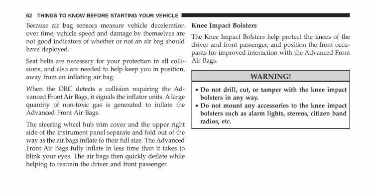
Knee Impact Bolsters
The Knee Impact Bolsters help protect the knees of thedriver and front passenger, and position the front occu-pants for improved interaction with the Advanced FrontAir Bags.
WARNING!
• Do not drill, cut, or tamper with the knee impactbolsters in any way.
• Do not mount any accessories to the knee impactbolsters such as alarm lights, stereos, citizen bandradios, etc.
62 THINGS TO KNOW BEFORE STARTING YOUR VEHICLE

Supplemental Driver Side Knee Air Bag
The Supplemental Driver Side Knee Air Bag providesenhanced protection and works together with the DriverAdvanced Front Air Bag during a frontal impact.
Along with seat belts and pretensioners, Advanced FrontAir Bags work with the Supplemental Knee Air Bag toprovide improved protection for the driver.
Supplemental Side Air Bags
Your vehicle is equipped with two types of side air bags:
Supplemental Seat-Mounted Side Air Bags (SAB): Lo-cated in the outboard side of the front and rear (invehicles equipped with rear seat SAB) seats. The SABsare marked with an air bag label sewn into the outboardside of the seats.
The SABs may help to reduce the risk of occupant injuryduring certain side impacts, in addition to the injuryreduction potential provided by the seat belts and bodystructure.
When the SAB deploys, it opens the seam on the out-board side of the seatback’s trim cover (front seats) and
Supplemental Seat-Mounted Side Air Bag Label
2
THINGS TO KNOW BEFORE STARTING YOUR VEHICLE 63
the seam on the outboard side of the seat cushion’s trimcover (outboard rear seats — if equipped with rear SABs).The inflating SAB deploys through the seat seam into thespace between the occupant and the door. The SABmoves at a very high speed and with such a high forcethat it could injure you if you are not seated properly, orif items are positioned in the area where the SAB inflates.Children are at an even greater risk of injury from adeploying air bag.
WARNING!
Do not use accessory seat covers or place objectsbetween you and the Side Air Bags; the performancecould be adversely affected and/or objects could bepushed into you, causing serious injury.
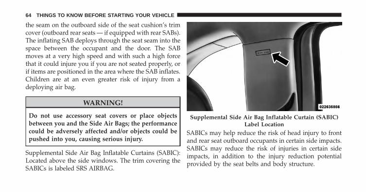
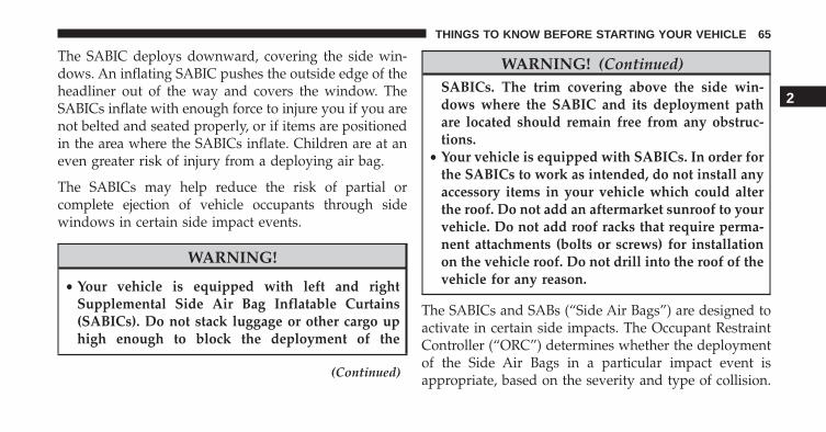
Supplemental Side Air Bag Inflatable Curtains (SABIC):Located above the side windows. The trim covering theSABICs is labeled SRS AIRBAG.
SABICs may help reduce the risk of head injury to frontand rear seat outboard occupants in certain side impacts.SABICs may reduce the risk of injuries in certain sideimpacts, in addition to the injury reduction potentialprovided by the seat belts and body structure.
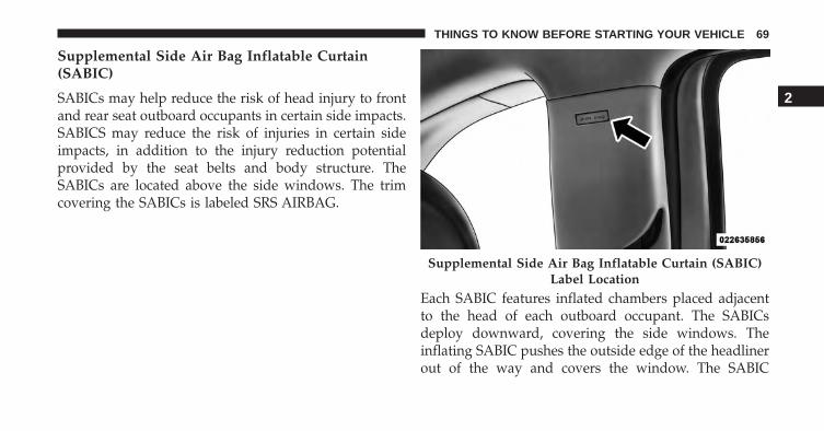
Supplemental Side Air Bag Inflatable Curtain (SABIC)Label Location
64 THINGS TO KNOW BEFORE STARTING YOUR VEHICLE
The SABIC deploys downward, covering the side win-dows. An inflating SABIC pushes the outside edge of theheadliner out of the way and covers the window. TheSABICs inflate with enough force to injure you if you arenot belted and seated properly, or if items are positionedin the area where the SABICs inflate. Children are at aneven greater risk of injury from a deploying air bag.
The SABICs may help reduce the risk of partial orcomplete ejection of vehicle occupants through sidewindows in certain side impact events.
WARNING!
• Your vehicle is equipped with left and rightSupplemental Side Air Bag Inflatable Curtains(SABICs). Do not stack luggage or other cargo uphigh enough to block the deployment of the
(Continued)
WARNING! (Continued)SABICs. The trim covering above the side win-dows where the SABIC and its deployment pathare located should remain free from any obstruc-tions.
• Your vehicle is equipped with SABICs. In order forthe SABICs to work as intended, do not install anyaccessory items in your vehicle which could alterthe roof. Do not add an aftermarket sunroof to yourvehicle. Do not add roof racks that require perma-nent attachments (bolts or screws) for installationon the vehicle roof. Do not drill into the roof of thevehicle for any reason.
The SABICs and SABs (“Side Air Bags”) are designed toactivate in certain side impacts. The Occupant RestraintController (“ORC”) determines whether the deploymentof the Side Air Bags in a particular impact event isappropriate, based on the severity and type of collision.
2
THINGS TO KNOW BEFORE STARTING YOUR VEHICLE 65

The side impact sensors aid the ORC in determining theappropriate response to impact events. The system iscalibrated to deploy the Side Air Bags on the impact sideof the vehicle during impacts that require Side Air Bagoccupant protection. In side impacts, the Side Air Bagsdeploy independently; a left side impact deploys the leftSide Air Bags only and a right-side impact deploys theright Side Air Bags only. Vehicle damage by itself is not agood indicator of whether or not Side Air Bags shouldhave deployed.
The Side Air Bags will not deploy in all side collisions,including some collisions at certain angles, or some sidecollisions that do not impact the area of the passengercompartment. The Side Air Bags may deploy duringangled or offset frontal collisions where the AdvancedFront Air Bags deploy.
Side Air Bags are a supplement to the seat belt restraintsystem. Side Air Bags deploy in less time than it takes to
blink your eyes. Occupants, including children, who areup against or very close to Side Air Bags can be seriouslyinjured or killed. Occupants, including children, shouldnever lean on or sleep against the door, side windows, orarea where the Side Air Bags inflate, even if they are in aninfant or child restraint.
Seat belts and child restraints are necessary for yourprotection in all types of collisions. They also help keepyou in position, away from an inflating air bag. To get thebest protection from the side air bags, occupants mustwear their seat belts properly and sit upright with theirbacks against the seats. Children must be properly re-strained in a child restraint or booster seat that isappropriate for the size of the child. Child restraints, likeseat belts, help keep children away from the path of theside air bag.
66 THINGS TO KNOW BEFORE STARTING YOUR VEHICLE

WARNING!
• Side Air bags need room to inflate. Do not leanagainst the door or window. Sit upright in thecenter of the seat.
• Being too close to the Side Air Bags during deploy-ment could cause you to be severely injured orkilled.
• Relying on the Side Air Bags alone could lead tomore severe injuries in a collision. The Side AirBags work with your seat belt to restrain youproperly. In some collisions, Side Air Bags won’tdeploy at all. Always wear your seat belt eventhough you have Side Air Bags.
NOTE: Air Bag covers may not be obvious in the interiortrim, but they will open during air bag deployment.
Supplemental Seat-Mounted Side Air Bags (SAB)
This vehicle is equipped with Supplemental Seat-Mounted Side Air Bags (SAB). The SABs may help toreduce the risk of occupant injury during certain sideimpacts, in addition to the injury reduction potentialprovided by the seat belts and body structure.
The SABs are located in the outboard side of the seats.The SABs are marked with an air bag label sewn into theoutboard side of the seats.
2
THINGS TO KNOW BEFORE STARTING YOUR VEHICLE 67

When the SAB deploys, it opens the seam on the side ofthe seat’s trim cover (front seats) and between the sideseat’s cushion trim cover (rear seats — if equipped withrear SAB). The inflating SAB exits through the seat seaminto the space between the occupant and the door.
The SAB moves at a very high speed and with such ahigh force that it could injure you if you are not seatedproperly, or if items are positioned in the area where theSAB inflates. Children are at an even greater risk of injuryfrom a deploying air bag.
To get the best protection from the SABs, occupants mustwear their seat belts properly and sit upright with theirbacks against the seats. Children must be properly re-strained in a child restraint or booster seat this is appro-priate for the size of the child. Child restraints, like seatbelts, help keep children away from the path of the SAB.
WARNING!
Do not use accessory seat covers or place objectsbetween you and the Side Air Bags; the performancecould be adversely affected and/or objects could bepushed into you, causing serious injury.
Supplemental Seat-Mounted Side Air Bag Label
68 THINGS TO KNOW BEFORE STARTING YOUR VEHICLE
Supplemental Side Air Bag Inflatable Curtain(SABIC)
SABICs may help reduce the risk of head injury to frontand rear seat outboard occupants in certain side impacts.SABICS may reduce the risk of injuries in certain sideimpacts, in addition to the injury reduction potentialprovided by the seat belts and body structure. TheSABICs are located above the side windows. The trimcovering the SABICs is labeled SRS AIRBAG.
Each SABIC features inflated chambers placed adjacentto the head of each outboard occupant. The SABICsdeploy downward, covering the side windows. Theinflating SABIC pushes the outside edge of the headlinerout of the way and covers the window. The SABIC
Supplemental Side Air Bag Inflatable Curtain (SABIC)Label Location
2
THINGS TO KNOW BEFORE STARTING YOUR VEHICLE 69

inflates with enough force to injure you if you are notbelted and seated properly, or if items are positioned inthe area where the SABIC inflates. Children are at aneven greater risk of injury from a deploying air bag.
To get the best protection from the SABICs, occupantsmust wear their seat belts properly and sit upright withtheir backs against the seats. Children must be properlyrestrained in a child restraint or booster seat this isappropriate for the size of the child. Child restraints, likeseat belts, help keep children away from the path of theSABIC.
The SABICs may help reduce the risk of partial orcomplete ejection of vehicle occupants through sidewindows in certain side impact events.
WARNING!
Your vehicle is equipped with left and right Supple-mental Side Air Bag Inflatable Curtains (SABIC). Donot stack luggage or other cargo up high enough toblock the deployment of the SABIC. The trim cover-ing above the side windows where the SABIC and itsdeployment path are located should remain free fromany obstructions.
WARNING!
Your vehicle is equipped with SABIC air bags. Inorder for the SABIC to work as intended, do notinstall any accessory items in your vehicle whichcould alter the roof. Do not add an aftermarketsunroof to your vehicle. Do not add roof racks thatrequire permanent attachments (bolts or screws) for
(Continued)
70 THINGS TO KNOW BEFORE STARTING YOUR VEHICLE

WARNING! (Continued)installation on the vehicle roof. Do not drill into theroof of the vehicle for any reason.
If A Deployment Occurs
The Advanced Front Air Bags are designed to deflateimmediately after deployment.
NOTE: Front and/or side air bags will not deploy in allcollisions. This does not mean something is wrong withthe air bag system.
If you do have a collision, which deploys the air bags, anyor all of the following may occur:
• The air bag material may sometimes cause abrasionsand/or skin reddening to the occupants as the air bagsdeploy and unfold. The abrasions are similar to fric-tion rope burns or those you might get sliding along acarpet or gymnasium floor. They are not caused by
contact with chemicals. They are not permanent andnormally heal quickly. However, if you haven’t healedsignificantly within a few days, or if you have anyblistering, see your doctor immediately.
• As the air bags deflate, you may see some smoke-likeparticles. The particles are a normal by-product of theprocess that generates the non-toxic gas used for airbag inflation. These airborne particles may irritate theskin, eyes, nose, or throat. If you have skin or eyeirritation, rinse the area with cool water. For nose orthroat irritation, move to fresh air. If the irritationcontinues, see your doctor. If these particles settle onyour clothing, follow the garment manufacturer’s in-structions for cleaning.
Do not drive your vehicle after the air bags have de-ployed. If you are involved in another collision, the airbags will not be in place to protect you.
2
THINGS TO KNOW BEFORE STARTING YOUR VEHICLE 71
WARNING!
Deployed air bags and seat belt pretensioners cannotprotect you in another collision. Have the air bags,seat belt pretensioners, and the seat belt retractorassemblies replaced by an authorized dealer imme-diately. Also, have the Occupant Restraint ControllerSystem serviced as well.
NOTE:
• Air bag covers may not be obvious in the interior trim,but they will open during air bag deployment.
• After any collision, the vehicle should be taken to anauthorized dealer immediately.
Enhanced Accident Response System
In the event of an impact, if the communication networkremains intact, and the power remains intact, dependingon the nature of the event, the ORC will determinewhether to have the Enhanced Accident Response Sys-tem perform the following functions:
• Cut off fuel to the engine.
• Flash hazard lights as long as the battery has power oruntil the ignition switch is turned to the “OFF” posi-tion.
• Turn on the interior lights, which remain on as long asthe battery has power or until the ignition switch isturned to the “OFF” position.
• Unlock the doors automatically.
72 THINGS TO KNOW BEFORE STARTING YOUR VEHICLE

Air Bag Warning Light
The air bags must be ready to inflate for yourprotection in a collision. The Air Bag WarningLight monitors the internal circuits and inter-connecting wiring associated with air bag sys-
tem electrical components.
The ORC monitors the readiness of the elec-tronic parts of the air bag system whenever theignition switch is in the START or ON/RUNposition. If the ignition switch is in the OFF
position or in the ACC position, the air bag system is noton and the air bags will not inflate.
The ORC contains a backup power supply system thatmay deploy the air bags even if the battery loses power orit becomes disconnected prior to deployment.
Also, the ORC turns on the Air Bag Warning Light in theinstrument panel for approximately four to eight seconds
for a self-check when the ignition switch is first turned tothe ON/RUN position. After the self-check, the Air BagWarning Light will turn off. If the ORC detects a mal-function in any part of the system, it turns on the Air BagWarning Light, either momentarily or continuously. Asingle chime will sound to alert you if the light comes onagain after initial startup.
The ORC also includes diagnostics that will illuminatethe instrument cluster Air Bag Warning Light if a mal-function is detected that could affect the air bag system.The diagnostics also record the nature of the malfunction.While the air bag system is designed to be maintenancefree, if any of the following occurs, have an authorizeddealer service the air bag system immediately.
• The Air Bag Warning Light does not come on duringthe four to eight seconds when the ignition switch isfirst turned to the ON/RUN position.
2
THINGS TO KNOW BEFORE STARTING YOUR VEHICLE 73

• The Air Bag Warning Light remains on after the four toeight-second interval.
• The Air Bag Warning Light comes on intermittently orremains on while driving.
NOTE: If the speedometer, tachometer, or any enginerelated gauges are not working, the Occupant RestraintController (ORC) may also be disabled. In this conditionthe air bags may not be ready to inflate for your protec-tion. Have an authorized dealer service the air bagsystem immediately.
WARNING!
Ignoring the Air Bag Warning Light in your instru-ment panel could mean you won’t have the air bagsto protect you in a collision. If the light does not comeon as a bulb check when the ignition is first turned
(Continued)
WARNING! (Continued)on, stays on after you start the vehicle, or if it comeson as you drive, have an authorized dealer service theair bag system immediately.
Maintaining Your Air Bag System
WARNING!
• Modifications to any part of the air bag systemcould cause it to fail when you need it. You couldbe injured if the air bag system is not there toprotect you. Do not modify the components orwiring, including adding any kind of badges orstickers to the steering wheel hub trim cover or theupper right side of the instrument panel. Do not
(Continued)
74 THINGS TO KNOW BEFORE STARTING YOUR VEHICLE
WARNING! (Continued)modify the front bumper, vehicle body structure, oradd aftermarket side steps or running boards.
• It is dangerous to try to repair any part of the airbag system yourself. Be sure to tell anyone whoworks on your vehicle that it has an air bag system.
• Do not attempt to modify any part of your air bagsystem. The air bag may inflate accidentally or maynot function properly if modifications are made.Take your vehicle to an authorized dealer for anyair bag system service. If your seat, including yourtrim cover and cushion, needs to be serviced in anyway (including removal or loosening/tightening ofseat attachment bolts), take the vehicle to yourauthorized dealer. Only manufacturer approvedseat accessories may be used. If it is necessary tomodify the air bag system for persons with dis-abilities, contact your authorized dealer.
Event Data Recorder (EDR)
This vehicle is equipped with an event data recorder(EDR). The main purpose of an EDR is to record, incertain crash or near crash-like situations, such as an airbag deployment or hitting a road obstacle, data that willassist in understanding how a vehicle’s systems per-formed. The EDR is designed to record data related tovehicle dynamics and safety systems for a short period oftime, typically 30 seconds or less. The EDR in this vehicleis designed to record such data as:
• How various systems in your vehicle were operating;
• Whether or not the driver and passenger seart beltswere buckled/fastened;
• How far (if at all) the driver was depressing theaccelerator and/or brake pedal; and,
• How fast the vehicle was traveling.
2
THINGS TO KNOW BEFORE STARTING YOUR VEHICLE 75
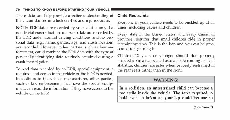
These data can help provide a better understanding ofthe circumstances in which crashes and injuries occur.
NOTE: EDR data are recorded by your vehicle only if anon-trivial crash situation occurs; no data are recorded bythe EDR under normal driving conditions and no per-sonal data (e.g., name, gender, age, and crash location)are recorded. However, other parties, such as law en-forcement, could combine the EDR data with the type ofpersonally identifying data routinely acquired during acrash investigation.
To read data recorded by an EDR, special equipment isrequired, and access to the vehicle or the EDR is needed.In addition to the vehicle manufacturer, other parties,such as law enforcement, that have the special equip-ment, can read the information if they have access to thevehicle or the EDR.
Child Restraints
Everyone in your vehicle needs to be buckled up at alltimes, including babies and children.
Every state in the United States, and every Canadianprovince, requires that small children ride in properrestraint systems. This is the law, and you can be pros-ecuted for ignoring it.
Children 12 years or younger should ride properlybuckled up in a rear seat, if available. According to crashstatistics, children are safer when properly restrained inthe rear seats rather than in the front.
WARNING!
In a collision, an unrestrained child can become aprojectile inside the vehicle. The force required tohold even an infant on your lap could become so
(Continued)
76 THINGS TO KNOW BEFORE STARTING YOUR VEHICLE

WARNING! (Continued)great that you could not hold the child, no matterhow strong you are. The child and others could bebadly injured. Any child riding in your vehicleshould be in a proper restraint for the child’s size.
There are different sizes and types of restraints forchildren from newborn size to the child almost largeenough for an adult seat belt. Always check the child seatOwner’s Manual to make sure you have the correct seatfor your child. Carefully read and follow all the instruc-tions and warnings in the child restraint Owner’s Manualand on all the labels attached to the child restraint.
Before buying any restraint system, make sure that it hasa label certifying that it meets all applicable SafetyStandards. You should also make sure that you can installit in the vehicle where you will use it.
NOTE:
• For additional information, refer to www.seatcheck.org orcall 1–866–SEATCHECK. Canadian residents should referto Transport Canada’s website for additional information:
• http://www.tc.gc.ca/eng/roadsafety/safedrivers-childsafety-index-53.htm
2
THINGS TO KNOW BEFORE STARTING YOUR VEHICLE 77
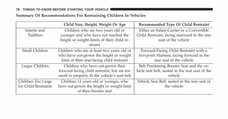
Summary Of Recommendations For Restraining Children In Vehicles
Child Size, Height, Weight Or Age Recommended Type Of Child RestraintInfants and
ToddlersChildren who are two years old or
younger and who have not reached theheight or weight limits of their child re-
straint
Either an Infant Carrier or a ConvertibleChild Restraint, facing rearward in the rear
seat of the vehicle
Small Children Children who are at least two years old orwho have out-grown the height or weight
limit of their rear-facing child restraint
Forward-Facing Child Restraint with afive-point Harness, facing forward in the
rear seat of the vehicleLarger Children Children who have out-grown their
forward-facing child restraint, but are toosmall to properly fit the vehicle’s seat belt
Belt Positioning Booster Seat and the ve-hicle seat belt, seated in the rear seat of the
vehicleChildren Too Largefor Child Restraints
Children 12 years old or younger, whohave out-grown the height or weight limit
of their booster seat
Vehicle Seat Belt, seated in the rear seat ofthe vehicle
78 THINGS TO KNOW BEFORE STARTING YOUR VEHICLE

Infants And Child Restraints
Safety experts recommend that children ride rearward-facing in the vehicle until they are two years old or untilthey reach either the height or weight limit of their rearfacing child safety seat. Two types of child restraints canbe used rearward-facing: infant carriers and convertiblechild seats.
The infant carrier is only used rearward-facing in thevehicle. It is recommended for children from birth untilthey reach the weight or height limit of the infant carrier.Convertible child seats can be used either rearward-facing or forward-facing in the vehicle. Convertible childseats often have a higher weight limit in the rearward-facing direction than infant carriers do, so they can beused rearward-facing by children who have outgrown
their infant carrier but are still less than at least two yearsold. Children should remain rearward-facing until theyreach the highest weight or height allowed by theirconvertible child seat.
WARNING!
• Never place a rear facing infant seat in front of anair bag. A deploying Passenger Advanced Front AirBag can cause death or serious injury to a child 12years or younger, including a child in a rearwardfacing infant seat.
• Only use a rearward-facing child restraint in avehicle with a rear seat.
2
THINGS TO KNOW BEFORE STARTING YOUR VEHICLE 79
Older Children And Child Restraints
Children who are two years old or who have outgrowntheir rear-facing convertible child seat can ride forward-facing in the vehicle. Forward-facing child seats andconvertible child seats used in the forward-facing direc-tion are for children who are over two years old or whohave outgrown the rear-facing weight or height limit oftheir rear-facing convertible child seat. Children shouldremain in a forward-facing child seat with a harness foras long as possible, up to the highest weight or heightallowed by the child seat.
All children whose weight or height is above theforward-facing limit for the child seat should use abelt-positioning booster seat until the vehicle’s seat beltsfit properly. If the child cannot sit with knees bent overthe vehicle’s seat cushion while the child’s back is againstthe seatback, they should use a belt-positioning boosterseat. The child and belt-positioning booster seat are heldin the vehicle by the seat belt.
80 THINGS TO KNOW BEFORE STARTING YOUR VEHICLE
WARNING!
• Improper installation can lead to failure of aninfant or child restraint. It could come loose in acollision. The child could be badly injured orkilled. Follow the child restraint manufacturer’sdirections exactly when installing an infant orchild restraint.
• After a child restraint is installed in the vehicle, donot move the vehicle seat forward or rearwardbecause it can loosen the child restraint attach-ments. Remove the child restraint before adjustingthe vehicle seat position. When the vehicle seat hasbeen adjusted, reinstall the child restraint.
(Continued)
WARNING! (Continued)• When your child restraint is not in use, secure it in
the vehicle with the seat belt or LATCH anchor-ages, or remove it from the vehicle. Do not leave itloose in the vehicle. In a sudden stop or accident, itcould strike the occupants or seatbacks and causeserious personal injury.
Children Too Large For Booster Seats
Children who are large enough to wear the shoulder beltcomfortably, and whose legs are long enough to bendover the front of the seat when their back is against theseatback, should use the seat belt in a rear seat. Use thissimple 5-step test to decide whether the child can use thevehicle’s seat belt alone:
1. Can the child sit all the way back against the back ofthe vehicle seat?
2
THINGS TO KNOW BEFORE STARTING YOUR VEHICLE 81
2. Do the child’s knees bend comfortably over the frontof the vehicle seat – while they are still sitting all theway back?
3. Does the shoulder belt cross the child’s shoulderbetween their neck and arm?
4. Is the lap part of the seat belt as low as possible,touching the child’s thighs and not their stomach?
5. Can the child stay seated like this for the whole trip?
If the answer to any of these questions was “no,” then thechild still needs to use a booster seat in this vehicle. If thechild is using the lap/shoulder belt, check seat belt fitperiodically and make sure the seat belt buckle is latched.A child’s squirming or slouching can move the seat beltout of position. If the shoulder belt contacts the face orneck, move the child closer to the center of the vehicle, oruse a booster seat to position the seat belt on the childcorrectly.
WARNING!
Never allow a child to put the shoulder belt under anarm or behind their back. In a crash, the shoulder beltwill not protect a child properly, which may result inserious injury or death. A child must always wearboth the lap and shoulder portions of the seat beltcorrectly.
82 THINGS TO KNOW BEFORE STARTING YOUR VEHICLE
Recommendations For Attaching Child Restraints
Restraint Type CombinedWeight of theChild + Child
Restraint
Use any attachment method shown with an “X” BelowLATCH –
Lower AnchorsOnly
Seat Belt Only LATCH –Lower Anchors
+ Top TetherAnchor
Seat Belt + TopTether Anchor
Rear-FacingChild Restraint
Up to 65 lbs(29.5 kg)
X X
Rear-FacingChild Restraint
More than65 lbs (29.5 kg)
X
Forward-FacingChild Restraint
Up to 65 lbs(29.5 kg)
X X
Forward-FacingChild Restraint
More than65 lbs (29.5 kg)
X
2
THINGS TO KNOW BEFORE STARTING YOUR VEHICLE 83
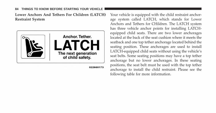
Lower Anchors And Tethers For Children (LATCH)Restraint System
Your vehicle is equipped with the child restraint anchor-age system called LATCH, which stands for LowerAnchors and Tethers for CHildren. The LATCH systemhas three vehicle anchor points for installing LATCH-equipped child seats. There are two lower anchorageslocated at the back of the seat cushion where it meets theseatback and one top tether anchorage located behind theseating position. These anchorages are used to installLATCH-equipped child seats without using the vehicle’sseat belts. Some seating positions may have a top tetheranchorage but no lower anchorages. In these seatingpositions, the seat belt must be used with the top tetheranchorage to install the child restraint. Please see thefollowing table for more information.
84 THINGS TO KNOW BEFORE STARTING YOUR VEHICLE
LATCH Positions For Installing Child Restraints InThis Vehicle
• Lower Anchorage Symbol 2 anchorages perseating position
• Top Tether Anchorage Symbol 2
THINGS TO KNOW BEFORE STARTING YOUR VEHICLE 85
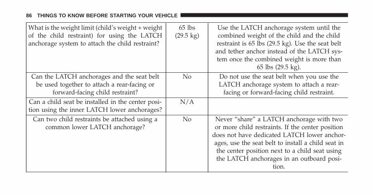
What is the weight limit (child’s weight + weightof the child restraint) for using the LATCHanchorage system to attach the child restraint?
65 lbs(29.5 kg)
Use the LATCH anchorage system until thecombined weight of the child and the childrestraint is 65 lbs (29.5 kg). Use the seat beltand tether anchor instead of the LATCH sys-tem once the combined weight is more than
65 lbs (29.5 kg).Can the LATCH anchorages and the seat belt
be used together to attach a rear-facing orforward-facing child restraint?
No Do not use the seat belt when you use theLATCH anchorage system to attach a rear-
facing or forward-facing child restraint.Can a child seat be installed in the center posi-tion using the inner LATCH lower anchorages?
N/A
Can two child restraints be attached using acommon lower LATCH anchorage?
No Never “share” a LATCH anchorage with twoor more child restraints. If the center position
does not have dedicated LATCH lower anchor-ages, use the seat belt to install a child seat inthe center position next to a child seat usingthe LATCH anchorages in an outboard posi-
tion.
86 THINGS TO KNOW BEFORE STARTING YOUR VEHICLE
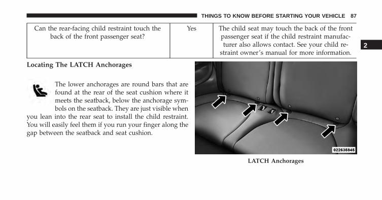
Can the rear-facing child restraint touch theback of the front passenger seat?
Yes The child seat may touch the back of the frontpassenger seat if the child restraint manufac-turer also allows contact. See your child re-
straint owner’s manual for more information.
Locating The LATCH Anchorages
The lower anchorages are round bars that arefound at the rear of the seat cushion where itmeets the seatback, below the anchorage sym-bols on the seatback. They are just visible when
you lean into the rear seat to install the child restraint.You will easily feel them if you run your finger along thegap between the seatback and seat cushion.
LATCH Anchorages
2
THINGS TO KNOW BEFORE STARTING YOUR VEHICLE 87

Locating The LATCH Anchorages
There are tether strap anchorages behind eachrear seating position located on the back of theseat.
LATCH-compatible child restraint systems will beequipped with a rigid bar or a flexible strap on each side.Each will have a hook or connector to attach to the loweranchorage and a way to tighten the connection to theanchorage. Forward-facing child restraints and somerear-facing child restraints will also be equipped with atether strap. The tether strap will have a hook at the endto attach to the top tether anchorage and a way to tightenthe strap after it is attached to the anchorage.
Center Seat LATCH
WARNING!
This vehicle does not have a center seating position.Do not use the center lower LATCH anchorages toinstall a child seat in the center of the back seat.
Always follow the directions of the child restraint manu-facturer when installing your child restraint. Not all childrestraint systems will be installed as described here.
To Install A LATCH-compatible Child Restraint
1. If the selected seating position has a Switchable Auto-matic Locking Retractor (ALR) seat belt, stow the seatbelt following the instructions below. See the section“Installing Child Restraints Using the Vehicle SeatBelt” to check what type of seat belt each seatingposition has.
88 THINGS TO KNOW BEFORE STARTING YOUR VEHICLE
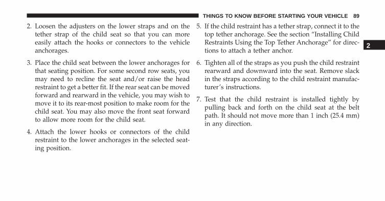
2. Loosen the adjusters on the lower straps and on thetether strap of the child seat so that you can moreeasily attach the hooks or connectors to the vehicleanchorages.
3. Place the child seat between the lower anchorages forthat seating position. For some second row seats, youmay need to recline the seat and/or raise the headrestraint to get a better fit. If the rear seat can be movedforward and rearward in the vehicle, you may wish tomove it to its rear-most position to make room for thechild seat. You may also move the front seat forwardto allow more room for the child seat.
4. Attach the lower hooks or connectors of the childrestraint to the lower anchorages in the selected seat-ing position.
5. If the child restraint has a tether strap, connect it to thetop tether anchorage. See the section “Installing ChildRestraints Using the Top Tether Anchorage” for direc-tions to attach a tether anchor.
6. Tighten all of the straps as you push the child restraintrearward and downward into the seat. Remove slackin the straps according to the child restraint manufac-turer’s instructions.
7. Test that the child restraint is installed tightly bypulling back and forth on the child seat at the beltpath. It should not move more than 1 inch (25.4 mm)in any direction.
2
THINGS TO KNOW BEFORE STARTING YOUR VEHICLE 89
How To Stow An Unused ALR Seat Belt
When using the LATCH attaching system to install achild restraint, stow all ALR seat belts that are not beingused by other occupants or being used to secure childrestraints. An unused belt could injure a child if they playwith it and accidentally lock the seatbelt retractor. Beforeinstalling a child restraint using the LATCH system,buckle the seat belt behind the child restraint and out ofthe child’s reach. If the buckled seat belt interferes withthe child restraint installation, instead of buckling itbehind the child restraint, route the seat belt through thechild restraint belt path and then buckle it. Do not lockthe seatbelt. Remind all children in the vehicle that theseat belts are not toys and that they should not play withthem.
WARNING!
• Improper installation of a child restraint to theLATCH anchorages can lead to failure of the re-straint. The child could be badly injured or killed.Follow the child restraint manufacturer’s directionsexactly when installing an infant or child restraint.
• Child restraint anchorages are designed to with-stand only those loads imposed by correctly-fittedchild restraints. Under no circumstances are they tobe used for adult seat belts, harnesses, or forattaching other items or equipment to the vehicle.
90 THINGS TO KNOW BEFORE STARTING YOUR VEHICLE

Installing Child Restraints Using The Vehicle SeatBelt
The seat belts in the passenger seating positions areequipped with a Switchable Automatic Locking Retractor(ALR) that is designed to keep the lap portion of the seatbelt tight around the child restraint so that it is notnecessary to use a locking clip. The ALR retractor can be“switched” into a locked mode by pulling all of thewebbing out of the retractor and then letting the webbingretract back into the retractor. If it is locked, the ALR willmake a clicking noise while the webbing is pulled backinto the retractor. For additional information on ALR,refer to the “Automatic Locking Mode” description un-der “Occupant Restraints.”
Lap/Shoulder Belt Systems for Installing ChildRestraints in this Vehicle
• ALR = Switchable Automatic Locking Retractor
• Top Tether Anchorage Symbol
2
THINGS TO KNOW BEFORE STARTING YOUR VEHICLE 91

What is the weight limit (child’sweight + weight of the child re-straint) for using the Tether Anchorwith the seat belt to attach a forwardfacing child restraint?
Weight limit of the Child Restraint Always use the tether anchor whenusing the seat belt to install a for-ward facing child restraint, up tothe recommended weight limit of
the child restraint.Can the rear-facing child restraint
touch the back of the front passen-ger seat?
Yes Contact between the front passen-ger seat and the child restraint is
allowed, if the child restraintmanufacturer also allows contact.
Can the head restraints be re-moved?
Yes Yes, all may be moved
Can the buckle stalk be twisted totighten the seat belt against the belt
path of the child restraint?
No Do not twist the buckle stalk in aseating position with an ALR re-
tractor.
92 THINGS TO KNOW BEFORE STARTING YOUR VEHICLE
Installing A Child Restraint With A SwitchableAutomatic Locking Retractor (ALR)
1. Place the child seat in the center of the seatingposition. For some second row seats, you may need torecline the seat and/or raise the head restraint to get abetter fit. If the rear seat can be moved forward andrearward in the vehicle, you may wish to move it to itsrear-most position to make room for the child seat.You may also move the front seat forward to allowmore room for the child seat.
2. Pull enough of the seat belt webbing from the retractorto pass it through the seat belt path of the childrestraint. Do not twist the belt webbing in the seat beltpath.
3. Slide the latch plate into the buckle until you hear a“click”.
4. Pull on the webbing to make the lap portion tightagainst the child seat.
5. To lock the seat belt, pull down on the shoulder part ofthe seat belt until you have pulled all the seat beltwebbing out of the retractor. Then, allow the webbingto retract back into the retractor. As the webbingretracts, you will hear a clicking sound. This means theseat belt is now in the Automatic Locking mode.
6. Try to pull the webbing out of the retractor. If it islocked, you should not be able to pull out any web-bing. If the retractor is not locked, repeat step 5.
7. Finally, pull up on any excess webbing to tighten thelap portion around the child restraint while you pushthe child restraint rearward and downward into thevehicle seat.
2
THINGS TO KNOW BEFORE STARTING YOUR VEHICLE 93
8. If the child restraint has a top tether strap and theseating position has a top tether anchorage, connectthe tether strap to the anchorage and tighten the tetherstrap. See the section “Installing Child RestraintsUsing the Top Tether Anchorage” for directions toattach a tether anchor.
9. Test that the child restraint is installed tightly bypulling back and forth on the child seat at the seat beltpath. It should not move more than 1 inch (25.4 mm)in any direction.
Any seat belt system will loosen with time, so check theseat belt occasionally, and pull it tight if necessary.
Installing Child Restraints Using The Top TetherAnchorage
1. Look behind the seating position where you plan toinstall the child restraint to find the tether anchorage.You may need to move the seat forward to provide
better access to the tether anchorage. If there is no toptether anchorage for that seating position, move thechild restraint to another position in the vehicle if oneis available.
2. Route the tether strap to provide the most direct pathfor the strap between the anchor and the child seat. Ifyour vehicle is equipped with adjustable rear headrestraints, raise the head restraint, and where possible,route the tether strap under the head restraint andbetween the two posts. If not possible, lower the headrestraint and pass the tether strap around the outboardside of the head restraint.
3. Attach the tether strap hook of the child restraint tothe top tether anchorage as shown in the diagram.
94 THINGS TO KNOW BEFORE STARTING YOUR VEHICLE
4. Remove slack in the tether strap according to the childrestraint manufacturer’s instructions.
WARNING!
• An incorrectly anchored tether strap could lead toincreased head motion and possible injury to thechild. Use only the anchorage position directlybehind the child seat to secure a child restraint toptether strap.
• If your vehicle is equipped with a split rear seat,make sure the tether strap does not slip into theopening between the seatbacks as you removeslack in the strap.
Transporting Pets
Air Bags deploying in the front seat could harm your pet.An unrestrained pet will be thrown about and possiblyinjured, or could injure a passenger during panic brakingor in a collision.
Pets should be restrained in the rear seat in pet harnessesor pet carriers that are secured by seat belts.
Rear Seat Tether Strap Mounting
2
THINGS TO KNOW BEFORE STARTING YOUR VEHICLE 95
SAFETY TIPS
Transporting Passengers
NEVER TRANSPORT PASSENGERS IN THE CARGOAREA.
WARNING!
• Do not leave children or animals inside parkedvehicles in hot weather. Interior heat build-up maycause serious injury or death.
• It is extremely dangerous to ride in a cargo area,inside or outside of a vehicle. In a collision, peopleriding in these areas are more likely to be seriouslyinjured or killed.
• Do not allow people to ride in any area of yourvehicle that is not equipped with seats and seatbelts.
(Continued)
WARNING! (Continued)• Be sure everyone in your vehicle is in a seat and
using a seat belt properly.
Safety Checks You Should Make Inside TheVehicle
Seat Belts
Inspect the seat belt system periodically, checking forcuts, frays, and loose parts. Damaged parts must bereplaced immediately. Do not disassemble or modify thesystem.
Front seat belt assemblies must be replaced after acollision. Rear seat belt assemblies must be replaced aftera collision if they have been damaged (i.e., bent retractor,torn webbing, etc.). If there is any question regarding seatbelt or retractor condition, replace the seat belt.
96 THINGS TO KNOW BEFORE STARTING YOUR VEHICLE

Air Bag Warning Light
The light should come on and remain on forfour to eight seconds as a bulb check when theignition switch is first turned ON. If the light isnot lit during starting, see your authorized
dealer. If the light stays on, flickers, or comes on whiledriving, have the system checked by an authorizeddealer.
Defroster
Check operation by selecting the defrost mode and placethe blower control on high speed. You should be able tofeel the air directed against the windshield. See yourauthorized dealer for service if your defroster is inoper-able.
Floor Mat Safety Information
Always use floor mats designed to fit the footwell of yourvehicle. Use only floor mats that leave the pedal areaunobstructed and that are firmly secured so that theycannot slip out of position and interfere with the pedalsor impair safe operation of your vehicle in other ways.
WARNING!
Pedals that cannot move freely can cause loss ofvehicle control and increase the risk of serious per-sonal injury.• Always make sure that floor mats are properly
attached to the floor mat fasteners.
(Continued)
2
THINGS TO KNOW BEFORE STARTING YOUR VEHICLE 97
WARNING! (Continued)• Never place or install floor mats or other floor
coverings in the vehicle that cannot be properlysecured to prevent them from moving and interfer-ing with the pedals or the ability to control thevehicle.
• Never put floor mats or other floor coverings on topof already installed floor mats. Additional floormats and other coverings will reduce the size of thepedal area and interfere with the pedals.
• Check mounting of mats on a regular basis. Alwaysproperly reinstall and secure floor mats that havebeen removed for cleaning.
(Continued)
WARNING! (Continued)• Always make sure that objects cannot fall into the
driver footwell while the vehicle is moving. Ob-jects can become trapped under the brake pedaland accelerator pedal causing a loss of vehiclecontrol.
• If required, mounting posts must be properly in-stalled, if not equipped from the factory.
Failure to properly follow floor mat installation ormounting can cause interference with the brakepedal and accelerator pedal operation causing loss ofcontrol of the vehicle.
98 THINGS TO KNOW BEFORE STARTING YOUR VEHICLE

Periodic Safety Checks You Should Make OutsideThe Vehicle
Tires
Examine tires for excessive tread wear and uneven wearpatterns. Check for stones, nails, glass, or other objectslodged in the tread or sidewall. Inspect the tread for cutsand cracks. Inspect sidewalls for cuts, cracks and bulges.Check the wheel bolts for tightness. Check the tires(including spare) for proper cold inflation pressure.
Lights
Have someone observe the operation of brake lights andexterior lights while you work the controls. Check turnsignal and high beam indicator lights on the instrumentpanel.
Door Latches
Check for positive closing, latching, and locking.
2
THINGS TO KNOW BEFORE STARTING YOUR VEHICLE 99


UNDERSTANDING THE FEATURES OF YOUR VEHICLE
CONTENTS� MIRRORS . . . . . . . . . . . . . . . . . . . . . . . . . . . .104
▫ Inside Day/Night Mirror . . . . . . . . . . . . . . . .104
▫ Automatic Dimming Mirror — If Equipped . . .104
▫ Power Mirrors . . . . . . . . . . . . . . . . . . . . . . .106
▫ Folding Mirrors . . . . . . . . . . . . . . . . . . . . . . .107
▫ Heated Mirrors — If Equipped . . . . . . . . . . .107
▫ Sun Visors . . . . . . . . . . . . . . . . . . . . . . . . . .108
� BLUE&ME™ HANDS-FREECOMMUNICATION . . . . . . . . . . . . . . . . . . . . .108
▫ Blue&Me™ Hands-Free CommunicationOverview — If Equipped . . . . . . . . . . . . . . . .108
▫ The Hands-Free Kit . . . . . . . . . . . . . . . . . . . .109
� SEATS . . . . . . . . . . . . . . . . . . . . . . . . . . . . . .115
▫ Front Seats Forward/Rearward Adjustment . . .116
▫ Recline Adjustment . . . . . . . . . . . . . . . . . . . .117
▫ Seat Height Adjustment . . . . . . . . . . . . . . . . .118
▫ EZ Entry Feature . . . . . . . . . . . . . . . . . . . . . .118
▫ Memory Feature . . . . . . . . . . . . . . . . . . . . . .119
3

▫ Heated Seats . . . . . . . . . . . . . . . . . . . . . . . .119
▫ Head Restraints . . . . . . . . . . . . . . . . . . . . . . .120
� TO OPEN AND CLOSE THE HOOD . . . . . . . . .122
� LIGHTS . . . . . . . . . . . . . . . . . . . . . . . . . . . . .125
▫ Multifunction Lever . . . . . . . . . . . . . . . . . . . .125
▫ Headlights . . . . . . . . . . . . . . . . . . . . . . . . . .125
▫ High Beams . . . . . . . . . . . . . . . . . . . . . . . . .126
▫ Flash-To-Pass . . . . . . . . . . . . . . . . . . . . . . . .126
▫ Parking Lights . . . . . . . . . . . . . . . . . . . . . . .126
▫ Daytime Running Lights — If Equipped . . . . .126
▫ Turn Signals . . . . . . . . . . . . . . . . . . . . . . . . .126
▫ Lane Change Assist . . . . . . . . . . . . . . . . . . .127
▫ Follow Me Home/Headlight Delay . . . . . . . . .127
▫ Interior Lights . . . . . . . . . . . . . . . . . . . . . . .128
▫ Front Fog Lights — If Equipped . . . . . . . . . . .129
� WINDSHIELD WIPERS AND WASHERS . . . . . .130
▫ Front Windshield Wiper Operation . . . . . . . . .130
▫ Rear Windshield Wiper . . . . . . . . . . . . . . . . .132
� TILT STEERING COLUMN — IF EQUIPPED . . .133
� ELECTRONIC SPEED CONTROL . . . . . . . . . . .134
▫ To Activate . . . . . . . . . . . . . . . . . . . . . . . . . .135
▫ To Set A Desired Speed . . . . . . . . . . . . . . . . .135
▫ To Deactivate . . . . . . . . . . . . . . . . . . . . . . . .135
▫ To Resume Speed . . . . . . . . . . . . . . . . . . . . .136
▫ To Vary The Speed Setting . . . . . . . . . . . . . . .136
▫ To Accelerate For Passing . . . . . . . . . . . . . . . .137
102 UNDERSTANDING THE FEATURES OF YOUR VEHICLE

� REAR PARK ASSIST — IF EQUIPPED . . . . . . . .138
▫ Rear Park Assist Sensors . . . . . . . . . . . . . . . .138
▫ Rear Park Assist Alerts. . . . . . . . . . . . . . . . . .139
▫ Failure Indications . . . . . . . . . . . . . . . . . . . . .142
� POWER SUNROOF — IF EQUIPPED . . . . . . . .143
▫ To Open . . . . . . . . . . . . . . . . . . . . . . . . . . . .144
▫ To Close . . . . . . . . . . . . . . . . . . . . . . . . . . . .144
▫ Pinch Protect Feature . . . . . . . . . . . . . . . . . . .145
▫ Wind Buffeting . . . . . . . . . . . . . . . . . . . . . . .145
▫ Emergency Operation. . . . . . . . . . . . . . . . . . .145
▫ Sun Shade — If Equipped . . . . . . . . . . . . . . .146
� ELECTRICAL POWER OUTLETS . . . . . . . . . . .146
� CIGAR LIGHTER — IF EQUIPPED . . . . . . . . . .149
� CUPHOLDERS . . . . . . . . . . . . . . . . . . . . . . . .149
� STORAGE . . . . . . . . . . . . . . . . . . . . . . . . . . . .150
▫ Glove Compartment . . . . . . . . . . . . . . . . . . .150
� CARGO AREA FEATURES . . . . . . . . . . . . . . . .151
� REAR WINDOW FEATURES . . . . . . . . . . . . . .152
▫ Rear Window Defroster . . . . . . . . . . . . . . . . .152
3
UNDERSTANDING THE FEATURES OF YOUR VEHICLE 103
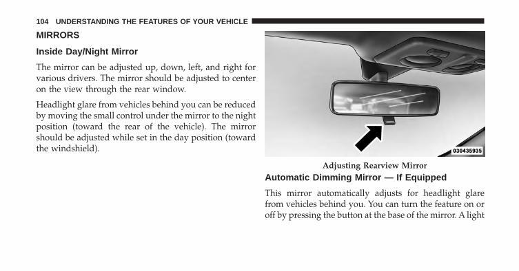
MIRRORS
Inside Day/Night Mirror
The mirror can be adjusted up, down, left, and right forvarious drivers. The mirror should be adjusted to centeron the view through the rear window.
Headlight glare from vehicles behind you can be reducedby moving the small control under the mirror to the nightposition (toward the rear of the vehicle). The mirrorshould be adjusted while set in the day position (towardthe windshield).
Automatic Dimming Mirror — If Equipped
This mirror automatically adjusts for headlight glarefrom vehicles behind you. You can turn the feature on oroff by pressing the button at the base of the mirror. A light
Adjusting Rearview Mirror
104 UNDERSTANDING THE FEATURES OF YOUR VEHICLE
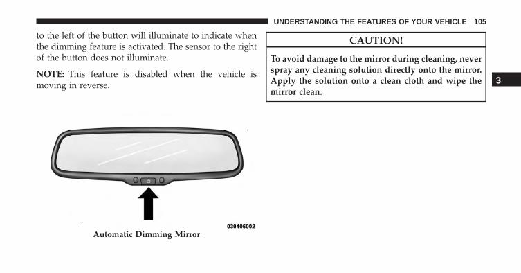
to the left of the button will illuminate to indicate whenthe dimming feature is activated. The sensor to the rightof the button does not illuminate.
NOTE: This feature is disabled when the vehicle ismoving in reverse.
CAUTION!
To avoid damage to the mirror during cleaning, neverspray any cleaning solution directly onto the mirror.Apply the solution onto a clean cloth and wipe themirror clean.
Automatic Dimming Mirror
3
UNDERSTANDING THE FEATURES OF YOUR VEHICLE 105

Power Mirrors
The power mirror controls are located on the driver’sdoor trim panel.
The power mirror controls consist of a mirror selectswitch and a four-way mirror control switch. To adjust a
mirror, press the mirror select switch to either the L (left)or R (right) to select the mirror you need to adjust.
Using the mirror control switch, press on any of the fourarrows for the direction that you want the mirror tomove.
WARNING!
Vehicles and other objects seen in the passenger sideconvex mirror will look smaller and farther awaythan they really are. Relying too much on yourpassenger side mirror could cause you to collide withanother vehicle or other object. Use your insidemirror when judging the size or distance of a vehicleseen in the passenger side convex mirror.
Power Mirror Switches
106 UNDERSTANDING THE FEATURES OF YOUR VEHICLE
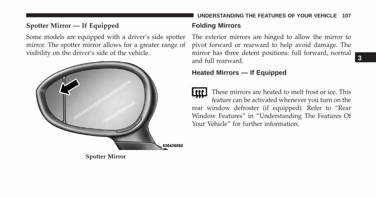
Spotter Mirror — If Equipped
Some models are equipped with a driver’s side spottermirror. The spotter mirror allows for a greater range ofvisibility on the driver’s side of the vehicle.
Folding Mirrors
The exterior mirrors are hinged to allow the mirror topivot forward or rearward to help avoid damage. Themirror has three detent positions: full forward, normaland full rearward.
Heated Mirrors — If Equipped
These mirrors are heated to melt frost or ice. Thisfeature can be activated whenever you turn on the
rear window defroster (if equipped). Refer to “RearWindow Features” in “Understanding The Features OfYour Vehicle” for further information.
Spotter Mirror
3
UNDERSTANDING THE FEATURES OF YOUR VEHICLE 107
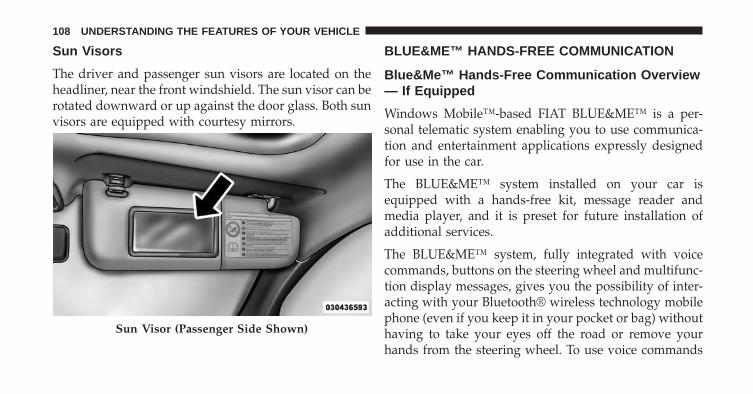
Sun Visors
The driver and passenger sun visors are located on theheadliner, near the front windshield. The sun visor can berotated downward or up against the door glass. Both sunvisors are equipped with courtesy mirrors.
BLUE&ME™ HANDS-FREE COMMUNICATION
Blue&Me™ Hands-Free Communication Overview— If Equipped
Windows Mobile™-based FIAT BLUE&ME™ is a per-sonal telematic system enabling you to use communica-tion and entertainment applications expressly designedfor use in the car.
The BLUE&ME™ system installed on your car isequipped with a hands-free kit, message reader andmedia player, and it is preset for future installation ofadditional services.
The BLUE&ME™ system, fully integrated with voicecommands, buttons on the steering wheel and multifunc-tion display messages, gives you the possibility of inter-acting with your Bluetooth® wireless technology mobilephone (even if you keep it in your pocket or bag) withouthaving to take your eyes off the road or remove yourhands from the steering wheel. To use voice commands
Sun Visor (Passenger Side Shown)
108 UNDERSTANDING THE FEATURES OF YOUR VEHICLE

you are not required to train the voice recognition systemto recognize your voice. This implies that the system isnearly equally performing with different persons, i.e.: thevoice recognition system is of the “speaker independent”type.
With this system you can also play your favorite musicstored on USB device and select tracks and playbackmodes with both voice commands or buttons on thesteering wheel.
This device complies with Part 15 of the FCC rulessubject to the following two conditions:
• This device may not cause harmful interference.
• This device must accept all interference received, in-cluding interference that may cause undesired opera-tion.
The Hands-Free Kit
The basic characteristic of this hands-free kit is voicerecognition with Bluetooth® wireless technology. Withthis system you can make and receive calls safely andsecurely by using either voice commands or buttons onthe steering wheel. This can be done under any drivingcondition without ever having to take your eyes off theroad or remove your hands from the steering wheel, asrequired by current laws.
Bluetooth® wireless technology enables wireless connec-tion between your mobile phone and the hands-free kitinstalled on your car.
To use the hands-free kit, you need a Bluetooth® wirelesstechnology enabled mobile phone. This hands-free kitgives you the possibility of interacting vocally with yourmobile phone while driving, even if your mobile devicedoes not feature this capability. You can also interact with
3
UNDERSTANDING THE FEATURES OF YOUR VEHICLE 109
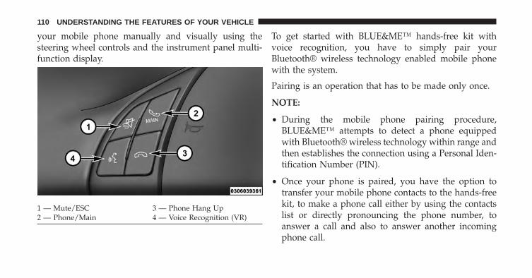
your mobile phone manually and visually using thesteering wheel controls and the instrument panel multi-function display.
To get started with BLUE&ME™ hands-free kit withvoice recognition, you have to simply pair yourBluetooth® wireless technology enabled mobile phonewith the system.
Pairing is an operation that has to be made only once.
NOTE:
• During the mobile phone pairing procedure,BLUE&ME™ attempts to detect a phone equippedwith Bluetooth® wireless technology within range andthen establishes the connection using a Personal Iden-tification Number (PIN).
• Once your phone is paired, you have the option totransfer your mobile phone contacts to the hands-freekit, to make a phone call either by using the contactslist or directly pronouncing the phone number, toanswer a call and also to answer another incomingphone call.
1 — Mute/ESC 3 — Phone Hang Up2 — Phone/Main 4 — Voice Recognition (VR)
110 UNDERSTANDING THE FEATURES OF YOUR VEHICLE
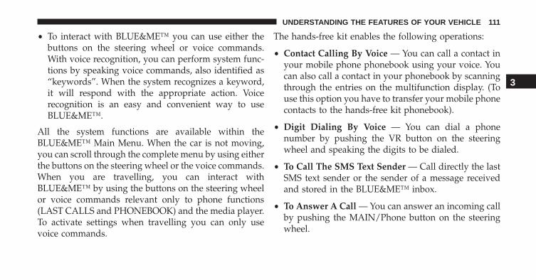
• To interact with BLUE&ME™ you can use either thebuttons on the steering wheel or voice commands.With voice recognition, you can perform system func-tions by speaking voice commands, also identified as“keywords”. When the system recognizes a keyword,it will respond with the appropriate action. Voicerecognition is an easy and convenient way to useBLUE&ME™.
All the system functions are available within theBLUE&ME™ Main Menu. When the car is not moving,you can scroll through the complete menu by using eitherthe buttons on the steering wheel or the voice commands.When you are travelling, you can interact withBLUE&ME™ by using the buttons on the steering wheelor voice commands relevant only to phone functions(LAST CALLS and PHONEBOOK) and the media player.To activate settings when travelling you can only usevoice commands.
The hands-free kit enables the following operations:
• Contact Calling By Voice — You can call a contact inyour mobile phone phonebook using your voice. Youcan also call a contact in your phonebook by scanningthrough the entries on the multifunction display. (Touse this option you have to transfer your mobile phonecontacts to the hands-free kit phonebook).
• Digit Dialing By Voice — You can dial a phonenumber by pushing the VR button on the steeringwheel and speaking the digits to be dialed.
• To Call The SMS Text Sender — Call directly the lastSMS text sender or the sender of a message receivedand stored in the BLUE&ME™ inbox.
• To Answer A Call — You can answer an incoming callby pushing the MAIN/Phone button on the steeringwheel.
3
UNDERSTANDING THE FEATURES OF YOUR VEHICLE 111
• Conference Call — You can call another contact whileyou are engaged in a phone conversation (withBluetooth® phones supporting this option).
• Call Waiting — While engaged in a phone conversa-tion, you can receive notification of another incomingphone call, answer the other incoming phone call, andswitch between two ongoing phone conversations.(Call waiting is only supported by a subset of compat-ible mobile phones).
• Refusing Incoming Call Or Ending A Call — You canrefuse an incoming call or end a current call bypushing the Phone Hang-up button on the steeringwheel.
After pairing and connecting your phone with theBLUE&ME™ system, you can make phone calls byspeaking keywords or pushing buttons on the steering
wheel. When using the hands-free phone, the audiooutput of a phone conversation is heard through your carsound speakers.
Message Reader
The BLUE&ME™ message reader enables automaticreading, through the car sound system, of the SMS textsyou receive on your Bluetooth® wireless technologymobile phone that are received when the phone is pairedand connected to the BLUE&ME™ system. It does notprovide access to messages that were received before thedevice was connected with the BLUE&ME™ system. Themessage reader will also interpret any abbreviation andemoticon contained in the SMS text.
112 UNDERSTANDING THE FEATURES OF YOUR VEHICLE
NOTE: Not all mobile phones support the SMS textmessage reader function or automatic phonebook transfervia Bluetooth®. For further information on the list ofcompatible mobile phones go to http://www.fiatusa.com,find the SUPPORT section near the bottom of web pageand click on the Bluetooth® logo.
Message reader functions are managed by the controlbuttons on the steering wheel or by the BLUE&ME™voice commands.
The BLUE&ME™ message reader enables the followingoperations:
• To display an indicator on the instrument panel thatindicates you have received a new SMS text. It willdisplay the sender’s number/name and will ask youwhether to read the text of the message to you.
• To manage the list of SMS texts received on yourBLUE&ME™ paired mobile phone.
• To read the messages received and stored. Messagescan be read multiple times.
• To call the SMS text sender using the buttons on thesteering wheel or voice commands.
• To delete individual messages or the entire inbox usingthe buttons on the steering wheel or voice commands.
The BLUE&ME™ system can also recognize and readabbreviations, if any (e.g. “ILUVU” will be read like “Ilove you”) and interpret the most usual emoticons (e.g. :-)will be read like “Smile”), that are currently used to writeSMS texts.
Media Player
With the BLUE&ME™ media player you can play, thedigital audio files stored on a USB device by simplyconnecting it to the USB port located in the glove box ofthe car.
3
UNDERSTANDING THE FEATURES OF YOUR VEHICLE 113
In this way, while you are driving you can play yourfavorite music collections.
• iPod® Player — See dedicated paragraph under Me-dia Player Functions.
The media player enables the following operations:
• Digital Audio Playback — You can play all yourdigital audio files (.mp3, .wma, .wav, .aac) or play acustomized playlist (.m3u or .wpl format).
• Audio File Selection By Category — You can play allaudio files of a certain category, e.g.: album, artist orgenre.
• Playback Options — While playing tracks you canselect the following options: Play, Stop, Next track,Previous track, Shuffle and Loop track.
NOTE:
• The media player does not support audio files com-pressed with other formats and DRM (Digital RightsManagement) protected audio files. Non-supportedaudio files that may be present on the USB device willbe ignored.
• To use the media player, you have to simply connect(directly or by an extension lead) your USB device tothe car USB port. After turning the ignition key to ON,BLUE&ME™ will start building your media library. Atthe end of this operation you can surf the completelibrary and scroll its categories as required using thebuttons on the steering wheel or voice commands.BLUE&ME™ will then play your selection via the carsound system.
114 UNDERSTANDING THE FEATURES OF YOUR VEHICLE

WARNING!
• Driving while distracted can result in loss of ve-hicle control, accident and injury. It is stronglyrecommended that you use extreme caution whenusing any device or feature that may take yourfocus off the road or your hands off the steeringwheel. Your primary responsibility is the safe op-eration of your vehicle.
• Read and Follow Instructions: before using yoursystem, read and follow all instructions and safetyinformation provided in this “Owner’s Manual”.Failure to do so can result in serious injury ordeath.
• Keep the Owner’s Manual in the car: when kept inthe car, the Owner’s Manual will be a ready refer-ence for you and other users unfamiliar with thesystem. Please make certain that before using the
(Continued)
WARNING! (Continued)system for the first time, all persons have access tothe Owner’s Manual and read its instructions andsafety information carefully.
SEATS
Seats are a part of the Occupant Restraint System of thevehicle.
WARNING!
• It is dangerous to ride in a cargo area, inside oroutside of a vehicle. In a collision, people riding inthese areas are more likely to be seriously injuredor killed.
• Do not allow people to ride in any area of yourvehicle that is not equipped with seats and seat
(Continued)
3
UNDERSTANDING THE FEATURES OF YOUR VEHICLE 115
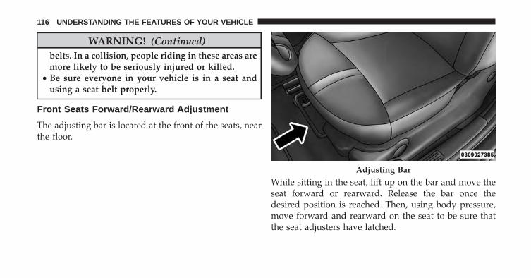
WARNING! (Continued)belts. In a collision, people riding in these areas aremore likely to be seriously injured or killed.
• Be sure everyone in your vehicle is in a seat andusing a seat belt properly.
Front Seats Forward/Rearward Adjustment
The adjusting bar is located at the front of the seats, nearthe floor.
While sitting in the seat, lift up on the bar and move theseat forward or rearward. Release the bar once thedesired position is reached. Then, using body pressure,move forward and rearward on the seat to be sure thatthe seat adjusters have latched.
Adjusting Bar
116 UNDERSTANDING THE FEATURES OF YOUR VEHICLE
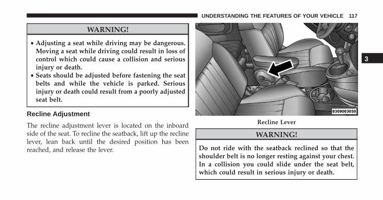
WARNING!
• Adjusting a seat while driving may be dangerous.Moving a seat while driving could result in loss ofcontrol which could cause a collision and seriousinjury or death.
• Seats should be adjusted before fastening the seatbelts and while the vehicle is parked. Seriousinjury or death could result from a poorly adjustedseat belt.
Recline Adjustment
The recline adjustment lever is located on the inboardside of the seat. To recline the seatback, lift up the reclinelever, lean back until the desired position has beenreached, and release the lever.
WARNING!
Do not ride with the seatback reclined so that theshoulder belt is no longer resting against your chest.In a collision you could slide under the seat belt,which could result in serious injury or death.
Recline Lever
3
UNDERSTANDING THE FEATURES OF YOUR VEHICLE 117
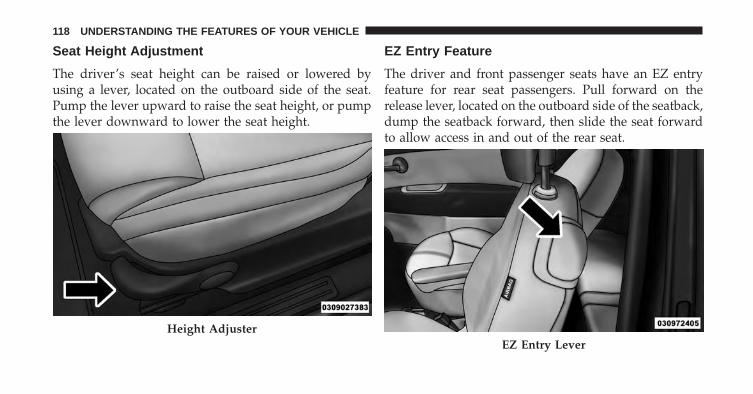
Seat Height Adjustment
The driver’s seat height can be raised or lowered byusing a lever, located on the outboard side of the seat.Pump the lever upward to raise the seat height, or pumpthe lever downward to lower the seat height.
EZ Entry Feature
The driver and front passenger seats have an EZ entryfeature for rear seat passengers. Pull forward on therelease lever, located on the outboard side of the seatback,dump the seatback forward, then slide the seat forwardto allow access in and out of the rear seat.
Height AdjusterEZ Entry Lever
118 UNDERSTANDING THE FEATURES OF YOUR VEHICLE
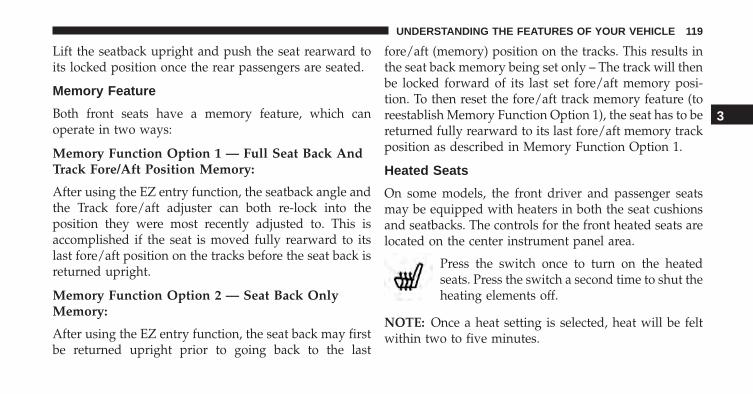
Lift the seatback upright and push the seat rearward toits locked position once the rear passengers are seated.
Memory Feature
Both front seats have a memory feature, which canoperate in two ways:
Memory Function Option 1 — Full Seat Back AndTrack Fore/Aft Position Memory:
After using the EZ entry function, the seatback angle andthe Track fore/aft adjuster can both re-lock into theposition they were most recently adjusted to. This isaccomplished if the seat is moved fully rearward to itslast fore/aft position on the tracks before the seat back isreturned upright.
Memory Function Option 2 — Seat Back OnlyMemory:
After using the EZ entry function, the seat back may firstbe returned upright prior to going back to the last
fore/aft (memory) position on the tracks. This results inthe seat back memory being set only – The track will thenbe locked forward of its last set fore/aft memory posi-tion. To then reset the fore/aft track memory feature (toreestablish Memory Function Option 1), the seat has to bereturned fully rearward to its last fore/aft memory trackposition as described in Memory Function Option 1.
Heated Seats
On some models, the front driver and passenger seatsmay be equipped with heaters in both the seat cushionsand seatbacks. The controls for the front heated seats arelocated on the center instrument panel area.
Press the switch once to turn on the heatedseats. Press the switch a second time to shut theheating elements off.
NOTE: Once a heat setting is selected, heat will be feltwithin two to five minutes.
3
UNDERSTANDING THE FEATURES OF YOUR VEHICLE 119
WARNING!
• Persons who are unable to feel pain to the skinbecause of advanced age, chronic illness, diabetes,spinal cord injury, medication, alcohol use, exhaus-tion or other physical condition must exercise carewhen using the seat heater. It may cause burnseven at low temperatures, especially if used forlong periods of time.
• Do not place anything on the seat or seatback thatinsulates against heat, such as a blanket or cushion.This may cause the seat heater to overheat. Sittingin a seat that has been overheated could causeserious burns due to the increased surface tempera-ture of the seat.
Head Restraints
Head restraints are designed to reduce the risk of injuryby restricting head movement in the event of a rear-impact. Head restraints should be adjusted so that the topof the head restraint is located above the top of your ear.
WARNING!
The head restraints for all occupants must be prop-erly adjusted prior to operating the vehicle or occu-pying a seat. Head restraints should never be ad-justed while the vehicle is in motion. Driving avehicle with the head restraints improperly adjustedor removed could cause serious injury or death in theevent of a collision.
120 UNDERSTANDING THE FEATURES OF YOUR VEHICLE
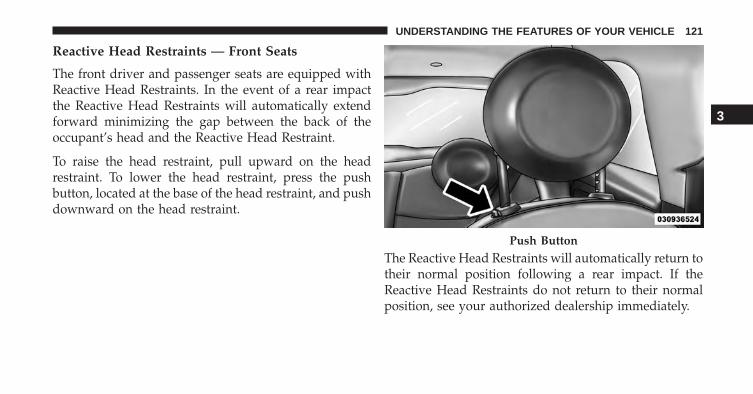
Reactive Head Restraints — Front Seats
The front driver and passenger seats are equipped withReactive Head Restraints. In the event of a rear impactthe Reactive Head Restraints will automatically extendforward minimizing the gap between the back of theoccupant’s head and the Reactive Head Restraint.
To raise the head restraint, pull upward on the headrestraint. To lower the head restraint, press the pushbutton, located at the base of the head restraint, and pushdownward on the head restraint.
The Reactive Head Restraints will automatically return totheir normal position following a rear impact. If theReactive Head Restraints do not return to their normalposition, see your authorized dealership immediately.
Push Button
3
UNDERSTANDING THE FEATURES OF YOUR VEHICLE 121
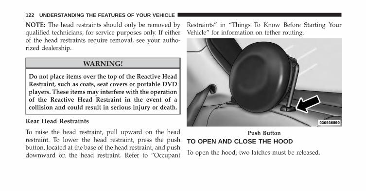
NOTE: The head restraints should only be removed byqualified technicians, for service purposes only. If eitherof the head restraints require removal, see your autho-rized dealership.
WARNING!
Do not place items over the top of the Reactive HeadRestraint, such as coats, seat covers or portable DVDplayers. These items may interfere with the operationof the Reactive Head Restraint in the event of acollision and could result in serious injury or death.
Rear Head Restraints
To raise the head restraint, pull upward on the headrestraint. To lower the head restraint, press the pushbutton, located at the base of the head restraint, and pushdownward on the head restraint. Refer to “Occupant
Restraints” in “Things To Know Before Starting YourVehicle” for information on tether routing.
TO OPEN AND CLOSE THE HOOD
To open the hood, two latches must be released.
Push Button
122 UNDERSTANDING THE FEATURES OF YOUR VEHICLE
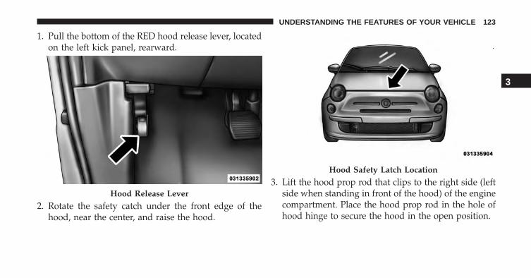
1. Pull the bottom of the RED hood release lever, locatedon the left kick panel, rearward.
2. Rotate the safety catch under the front edge of thehood, near the center, and raise the hood.
3. Lift the hood prop rod that clips to the right side (leftside when standing in front of the hood) of the enginecompartment. Place the hood prop rod in the hole ofhood hinge to secure the hood in the open position.
Hood Release Lever
Hood Safety Latch Location
3
UNDERSTANDING THE FEATURES OF YOUR VEHICLE 123
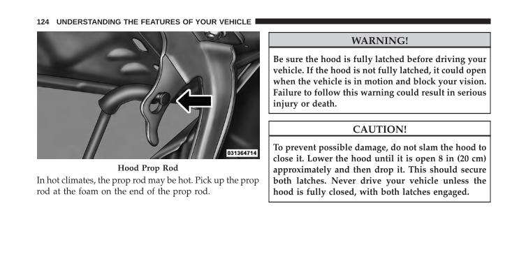
In hot climates, the prop rod may be hot. Pick up the proprod at the foam on the end of the prop rod.
WARNING!
Be sure the hood is fully latched before driving yourvehicle. If the hood is not fully latched, it could openwhen the vehicle is in motion and block your vision.Failure to follow this warning could result in seriousinjury or death.
CAUTION!
To prevent possible damage, do not slam the hood toclose it. Lower the hood until it is open 8 in (20 cm)approximately and then drop it. This should secureboth latches. Never drive your vehicle unless thehood is fully closed, with both latches engaged.
Hood Prop Rod
124 UNDERSTANDING THE FEATURES OF YOUR VEHICLE

LIGHTS
Multifunction Lever
The multifunction lever, located on the left side of thesteering wheel, controls the operation of the headlights,headlight beam selection, passing light and turn signals.
NOTE: The external lights can only be turned on withthe ignition in the ON/RUN position.
Headlights
Rotate the end of the multifunction lever up-ward to the first detent for headlight operation.
NOTE: When the headlights are turned on, the DaytimeRunning Lights will be deactivated.
Headlight Operation
3
UNDERSTANDING THE FEATURES OF YOUR VEHICLE 125
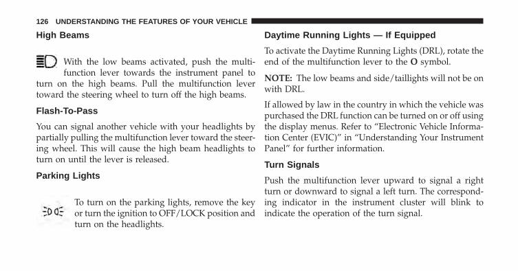
High Beams
With the low beams activated, push the multi-function lever towards the instrument panel to
turn on the high beams. Pull the multifunction levertoward the steering wheel to turn off the high beams.
Flash-To-Pass
You can signal another vehicle with your headlights bypartially pulling the multifunction lever toward the steer-ing wheel. This will cause the high beam headlights toturn on until the lever is released.
Parking Lights
To turn on the parking lights, remove the keyor turn the ignition to OFF/LOCK position andturn on the headlights.
Daytime Running Lights — If Equipped
To activate the Daytime Running Lights (DRL), rotate theend of the multifunction lever to the O symbol.
NOTE: The low beams and side/taillights will not be onwith DRL.
If allowed by law in the country in which the vehicle waspurchased the DRL function can be turned on or off usingthe display menus. Refer to “Electronic Vehicle Informa-tion Center (EVIC)” in “Understanding Your InstrumentPanel” for further information.
Turn Signals
Push the multifunction lever upward to signal a rightturn or downward to signal a left turn. The correspond-ing indicator in the instrument cluster will blink toindicate the operation of the turn signal.
126 UNDERSTANDING THE FEATURES OF YOUR VEHICLE

NOTE: The indicators will automatically turn off whenthe turn has been completed and the steering wheel isreturned to a straight position.
Lane Change Assist
Tap the lever up or down once, without moving beyondthe detent, and the turn signal (right or left) will flashthree times then automatically turn off.
Follow Me Home/Headlight Delay
When this feature is selected the driver can choose tohave the headlights remain on for a preset period of time.
Activation
Remove the key or turn the ignition to the OFF/LOCKposition, and pull the multifunction lever toward thesteering wheel, within two minutes. Each time the leveris pulled, the activation of the lights will be extended by30 seconds. The activation of the lights can be extended toa maximum of 210 seconds.
Turn Signal Operation
3
UNDERSTANDING THE FEATURES OF YOUR VEHICLE 127
Deactivation
Pull the multifunction lever toward the steering wheeland hold it for more than two seconds.
Interior Lights
The interior light switches are located in the overheadconsole. The interior lights can be set to three differentpositions (Off/Left Position, Center Position, On/RightPosition).
Using the switch on the left overhead, press the switch tothe right from its center position and the lights are alwayson. Press the switch to the left from its center position andthe lights are always off. Leave the switch in the centerposition, and the lights are turned on and off when thedoors are opened or closed. The switch on the right sideof the overhead console controls the map or readingfunction of the lights. Press the switch to the right to turn
on the right light and press the switch to the left to turnon the left light.
CAUTION!
Before getting out of the vehicle be sure that theswitch is in the center position or that the lights areoff to avoid draining the battery.
Interior Light Timing (Center Position)
There are four different modes of operation that can beactivated in this position:
• When one door is opened a three minute timer isactivated.
• When the key is removed from the ignition (withintwo minutes of the ignition being turned off), a 10second timer is activated.
128 UNDERSTANDING THE FEATURES OF YOUR VEHICLE

• When the doors are unlocked with the Key Fob a 10second timer is activated.
• When the doors are locked with the Key Fob the lightswill turn off.
Interior Light Timing (On/Right Position)
• When all doors are closed a 15 minute timer isactivated.
NOTE: The timer is deactivated when the key is movedinto the ON/RUN position.
Front Fog Lights — If Equipped
The fog light switch is located on the center stack of theinstrument panel, just below the radio.
Press the switch once to turn the front fog lights on. Pressthe switch a second time to turn the front fog lights off.
Fog Light Switch
3
UNDERSTANDING THE FEATURES OF YOUR VEHICLE 129
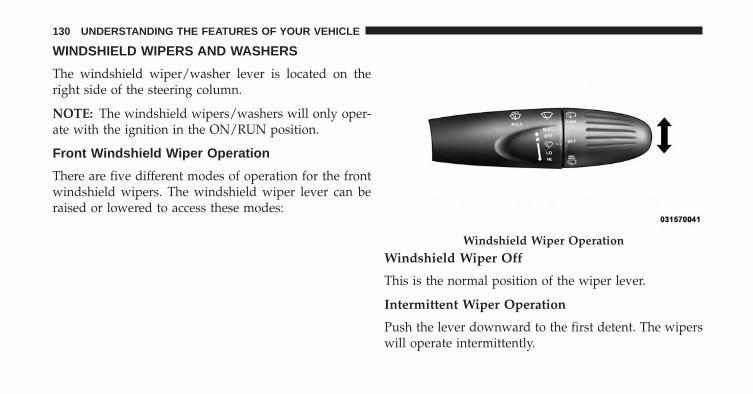
WINDSHIELD WIPERS AND WASHERS
The windshield wiper/washer lever is located on theright side of the steering column.
NOTE: The windshield wipers/washers will only oper-ate with the ignition in the ON/RUN position.
Front Windshield Wiper Operation
There are five different modes of operation for the frontwindshield wipers. The windshield wiper lever can beraised or lowered to access these modes:
Windshield Wiper Off
This is the normal position of the wiper lever.
Intermittent Wiper Operation
Push the lever downward to the first detent. The wiperswill operate intermittently.
Windshield Wiper Operation
130 UNDERSTANDING THE FEATURES OF YOUR VEHICLE

NOTE: The Intermittent function only has one detentbut wiper delay will vary with changes in vehicle speed.As vehicle speed increases the delay time will decrease.
Low Speed
Push the lever downward to the second detent. Thewipers will operate at low speed.
High Speed
Push the lever downward to the third detent. The wiperswill operate at high speed.
Manual High Speed/Mist
Push the lever upward from the off position. The wiperswill operate at high speed to clear off road mist or sprayfrom a passing vehicle. This operation will continue untilthe lever is released. When the lever is released, thewipers will return to the off position and automaticallyshut off.
Front Windshield Washer Operation
Pull the windshield wiper/washer lever toward thesteering wheel to activate the washers. The wipers willactivate automatically for three cycles after the lever isreleased.
CAUTION!
• Turn the windshield wipers off when drivingthrough an automatic car wash. Damage to thewindshield wipers may result if the wiper controlis left in any position other than off.
• In cold weather, always turn off the wiper switchand allow the wipers to return to the “Park” posi-tion before turning off the vehicle. If the wiperswitch is left on and the wipers freeze to thewindshield, damage to the wiper motor may occurwhen the vehicle is restarted.
(Continued)
3
UNDERSTANDING THE FEATURES OF YOUR VEHICLE 131
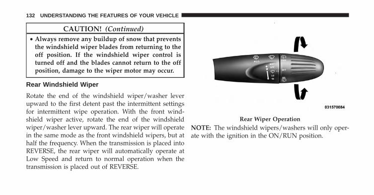
CAUTION! (Continued)• Always remove any buildup of snow that prevents
the windshield wiper blades from returning to theoff position. If the windshield wiper control isturned off and the blades cannot return to the offposition, damage to the wiper motor may occur.
Rear Windshield Wiper
Rotate the end of the windshield wiper/washer leverupward to the first detent past the intermittent settingsfor intermittent wipe operation. With the front wind-shield wiper active, rotate the end of the windshieldwiper/washer lever upward. The rear wiper will operatein the same mode as the front windshield wipers, but athalf the frequency. When the transmission is placed intoREVERSE, the rear wiper will automatically operate atLow Speed and return to normal operation when thetransmission is placed out of REVERSE.
NOTE: The windshield wipers/washers will only oper-ate with the ignition in the ON/RUN position.
Rear Wiper Operation
132 UNDERSTANDING THE FEATURES OF YOUR VEHICLE
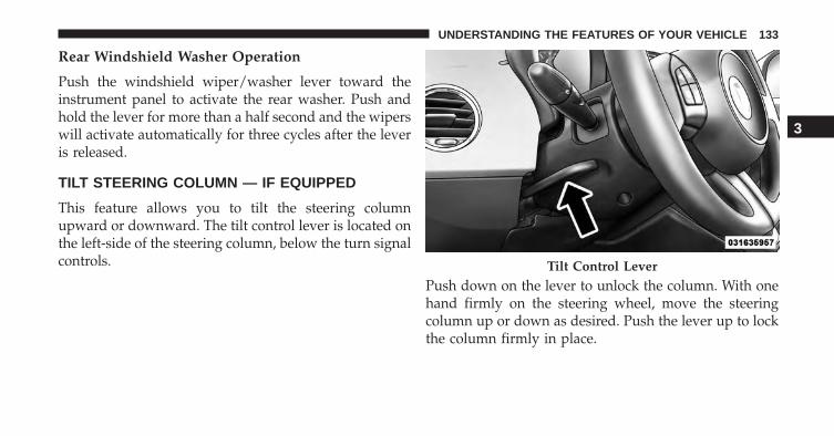
Rear Windshield Washer Operation
Push the windshield wiper/washer lever toward theinstrument panel to activate the rear washer. Push andhold the lever for more than a half second and the wiperswill activate automatically for three cycles after the leveris released.
TILT STEERING COLUMN — IF EQUIPPED
This feature allows you to tilt the steering columnupward or downward. The tilt control lever is located onthe left-side of the steering column, below the turn signalcontrols.
Push down on the lever to unlock the column. With onehand firmly on the steering wheel, move the steeringcolumn up or down as desired. Push the lever up to lockthe column firmly in place.
Tilt Control Lever
3
UNDERSTANDING THE FEATURES OF YOUR VEHICLE 133

WARNING!
Do not adjust the steering column while driving.Adjusting the steering column while driving or driv-ing with the steering column unlocked, could causethe driver to lose control of the vehicle. Failure tofollow this warning may result in serious injury ordeath.
ELECTRONIC SPEED CONTROL
When engaged, the Electronic Speed Control takes overaccelerator operations at speeds greater than 25 mph(40 km/h).
The Electronic Speed Control buttons are located on theright side of the steering wheel.
NOTE: In order to ensure proper operation, the Elec-tronic Speed Control system has been designed to shutdown if multiple Speed Control functions are operated atthe same time. If this occurs, the Electronic Speed Controlsystem can be reactivated by pushing the Electronic
Electronic Speed Control Buttons
134 UNDERSTANDING THE FEATURES OF YOUR VEHICLE

Speed Control ON/OFF button and resetting the desiredvehicle set speed.
To Activate
Push the ON/OFF button. The Cruise Indicator Light inthe instrument cluster will illuminate. To turn the systemoff, push the ON/OFF button a second time. The CruiseIndicator Light will turn off. The system should beturned off when not in use.
WARNING!
Leaving the Electronic Speed Control system onwhen not in use is dangerous. You could accidentallyset the system or cause it to go faster than you want.You could lose control and have an accident. Alwaysleave the system OFF when you are not using it.
To Set A Desired Speed
Turn the Electronic Speed Control ON. When the vehiclehas reached the desired speed, press the SET (-) buttonand release. Release the accelerator and the vehicle willoperate at the selected speed.
NOTE: The vehicle should be traveling at a steady speedand on level ground before pressing the SET (-) button.
To Deactivate
A soft tap on the brake pedal, pushing the CANC button,or normal brake pressure while slowing the vehicle willdeactivate Electronic Speed Control without erasing theset speed memory. Pressing the ON/OFF button orturning the ignition switch OFF erases the set speedmemory.
3
UNDERSTANDING THE FEATURES OF YOUR VEHICLE 135
To Resume Speed
To resume a previously set speed, push the RES (+)button and release. Resume can be used at any speedabove 20 mph (32 km/h).
To Vary The Speed Setting
To Increase Speed
When the Electronic Speed Control is set, you can in-crease speed by pushing the RES (+) button.
The speed increment shown is dependant on the speed ofU.S. (mph) or Metric (km/h) units:
U.S. Speed (mph)
• Pressing the RES (+) button once will result in a 1 mphincrease in set speed. Each subsequent tap of thebutton results in an increase of 1 mph.
• If the button is continually pressed, the set speed willcontinue to increase until the button is released, thenthe new set speed will be established.
Metric Speed (km/h)
• Pressing the RES (+) button once will result in a2 km/h increase in set speed. Each subsequent tap ofthe button results in an increase of 2 km/h.
• If the button is continually pressed, the set speed willcontinue to increase until the button is released, thenthe new set speed will be established.
To Decrease Speed
When the Electronic Speed Control is set, you can de-crease speed by pushing the SET (-) button.
136 UNDERSTANDING THE FEATURES OF YOUR VEHICLE
The speed decrement shown is dependant on the speedof U.S. (mph) or Metric (km/h) units:
U.S. Speed (mph)
• Pressing the SET (-) button once will result in a 1 mphdecrease in set speed. Each subsequent tap of thebutton results in a decrease of 1 mph.
• If the button is continually pressed, the set speed willcontinue to decrease until the button is released, thenthe new set speed will be established.
Metric Speed (km/h)
• Pressing the SET (-) button once will result in a 2 km/hdecrease in set speed. Each subsequent tap of thebutton results in a decrease of 2 km/h.
• If the button is continually pressed, the set speed willcontinue to decrease until the button is released, thenthe new set speed will be established.
To Accelerate For Passing
Press the accelerator as you would normally. When thepedal is released, the vehicle will return to the set speed.
Using Electronic Speed Control On Hills
NOTE: The Electronic Speed Control system maintainsspeed up and down hills. A slight speed change onmoderate hills is normal.
On steep hills, a greater speed loss or gain may occur soit may be preferable to drive without Electronic SpeedControl.
WARNING!
Electronic Speed Control can be dangerous where thesystem cannot maintain a constant speed. Your ve-hicle could go too fast for the conditions, and you
(Continued)
3
UNDERSTANDING THE FEATURES OF YOUR VEHICLE 137
WARNING! (Continued)could lose control and have an accident. Do not useElectronic Speed Control in heavy traffic or on roadsthat are winding, icy, snow-covered or slippery.
REAR PARK ASSIST — IF EQUIPPED
The Rear Park Assist system provides an audible indica-tion of the distance between the rear fascia/bumper anda detected obstacle when backing up, e.g. during aparking maneuver. Refer to the “Park Assist SystemUsage Precautions” for the limitations of this system andrecommendations.
Rear Park Assist is automatically activated when thetransmission is placed into REVERSE. As the distancefrom an obstacle behind the vehicle decreases, the au-dible alert becomes more frequent.
Rear Park Assist Sensors
The four Rear Park Assist sensors, located in the rearfascia/bumper, monitor the area behind the vehicle thatis within the sensors’ field of view. The sensors can detectobstacles, in the horizontal direction, from approximately12 in (30 cm) up to 55 in (140 cm) from the center of therear fascia/bumper and up to 24 in (60 cm) from thecorners of the rear fascia/bumper, depending on thelocation, type and orientation of the obstacle.
If several obstacles are detected, the Rear Park Assistsystem indicates the nearest obstacle.
The minimum height of a detectable obstacle corre-sponds to the maximum height of an obstacle that wouldclear the underside of the car during the parking maneu-ver.
138 UNDERSTANDING THE FEATURES OF YOUR VEHICLE
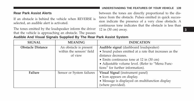
Rear Park Assist Alerts
If an obstacle is behind the vehicle when REVERSE isselected, an audible alert is activated.
The tones emitted by the loudspeaker inform the driverthat the vehicle is approaching an obstacle. The pauses
between the tones are directly proportional to the dis-tance from the obstacle. Pulses emitted in quick succes-sion indicate the presence of a very close obstacle. Acontinuous tone indicates that the obstacle is less than12 in (30 cm) away.
Audible And Visual Signals Supplied By The Rear Park Assist System
SIGNAL MEANING INDICATIONObstacle Distance An obstacle is present
within the sensors’ fieldof view
Audible signal (dashboard loudspeaker)• Sound pulses emitted at a rate that increases as thedistance decreases.• Emits continuous tone at 12 in (30 cm)• Adjustable volume level. (Refer to “Menu Func-tions” for further information).
Failure Sensor or System failures Visual Signal (instrument panel)• Icon appears on display.• Message is displayed on multifunction display(where provided).
3
UNDERSTANDING THE FEATURES OF YOUR VEHICLE 139
While audible signals are emitted, the audio system is notmuted.
The audible signal is cut out immediately if the distanceincreases. The tone cycle remains constant if the distancemeasured by the inner sensors is constant. If this condi-tion occurs for the external sensors, the signal is cut offafter 3 seconds (stopping warnings during maneuversparallel to walls).
Cleaning The Rear Park Assist System
Clean the Rear Park Assist sensors with water, car washsoap and a soft cloth. Do not use rough or hard cloths. Inwashing stations, clean sensors quickly keeping the va-por jet/high pressure washing nozzles at least 4 in(10 cm) from the sensors. Do not scratch or poke thesensors. Otherwise, you could damage the sensors.
Park Assist System Usage Precautions
NOTE:
• Ensure that the outer surface and the underside of therear bumper is clean and clear of snow, ice, mud, dirtor other obstruction to keep the Rear Park Assistsystem operating properly.
• Jackhammers, large trucks, and other vibrations couldaffect the performance of Rear Park Assist.
• Clean the Rear Park Assist sensors regularly, takingcare not to scratch or damage them. The sensors mustnot be covered with ice, snow, slush, mud, dirt ordebris. Failure to do so can result in the system notworking properly. The Rear Park Assist system mightnot detect an obstacle behind the fascia/bumper, or itcould provide a false indication that an obstacle isbehind the fascia/bumper.
140 UNDERSTANDING THE FEATURES OF YOUR VEHICLE
• Objects such as bicycle carriers, etc., must not beplaced within 12 in (30 cm) from the rear fascia/bumper while driving the vehicle. Failure to do so canresult in the system misinterpreting a close object as asensor problem, causing a failure indication to bedisplayed in the instrument cluster.
CAUTION!
• Rear Park Assist is only a parking aid and it isunable to recognize every obstacle, including smallobstacles. Parking curbs might be temporarily de-tected or not detected at all. Obstacles locatedabove or below the sensors will not be detectedwhen they are in close proximity.
CAUTION! (Continued)• The vehicle must be driven slowly when using
Rear Park Assist in order to be able to stop in timewhen an obstacle is detected. It is recommendedthat the driver looks over his/her shoulder whenusing Rear Park Assist.
WARNING!
• Drivers must be careful when backing up evenwhen using the Rear Park Assist system. Alwayscheck carefully behind your vehicle, look behindyou, and be sure to check for pedestrians, animals,other vehicles, obstructions, and blind spots before
(Continued)
3
UNDERSTANDING THE FEATURES OF YOUR VEHICLE 141
WARNING! (Continued)backing up. You are responsible for safety andmust continue to pay attention to your surround-ings. Failure to do so can result in serious injury ordeath.
• Before using the Rear Park Assist System, it isstrongly recommended that the ball mount andhitch ball assembly is disconnected from the ve-hicle when the vehicle is not used for towing.Failure to do so can result in injury or damage tovehicles or obstacles because the hitch ball will bemuch closer to the obstacle than the rear fasciawhen the warning display turns on the singleflashing arc and sounds the continuous tone. Also,the sensors could detect the ball mount and hitch
(Continued)
WARNING! (Continued)ball assembly, depending on its size and shape,giving a false indication that an obstacle is behindthe vehicle.
Failure Indications
A malfunction of the Rear Park Assist sensors or systemis indicated, during REVERSE engagement, by the instru-ment panel warning icon.
The warning icon is illuminated and a messageis displayed on the multifunction display (ifequipped). Refer to “Instrument Cluster De-scriptions” in “Understanding Your Instrument
Panel” for further information.
The sensors and wiring are tested continuously when theignition is in the ON/RUN position. Failures are indi-cated immediately if they occur when the system is ON.
142 UNDERSTANDING THE FEATURES OF YOUR VEHICLE
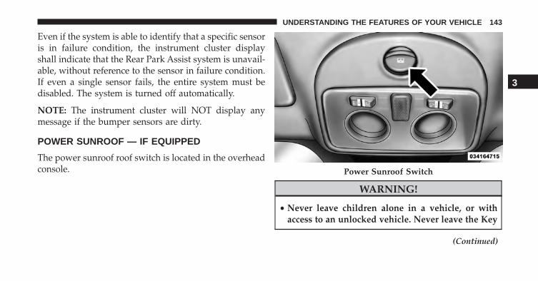
Even if the system is able to identify that a specific sensoris in failure condition, the instrument cluster displayshall indicate that the Rear Park Assist system is unavail-able, without reference to the sensor in failure condition.If even a single sensor fails, the entire system must bedisabled. The system is turned off automatically.
NOTE: The instrument cluster will NOT display anymessage if the bumper sensors are dirty.
POWER SUNROOF — IF EQUIPPED
The power sunroof roof switch is located in the overheadconsole.
WARNING!
• Never leave children alone in a vehicle, or withaccess to an unlocked vehicle. Never leave the Key
(Continued)
Power Sunroof Switch
3
UNDERSTANDING THE FEATURES OF YOUR VEHICLE 143
WARNING! (Continued)Fob in or near the vehicle, or in a location acces-sible to children. Occupants, particularly unat-tended children, can become entrapped by thepower sunroof while operating the power sunroofswitch. Such entrapment may result in seriousinjury or death.
• In a collision, there is a greater risk of being thrownfrom a vehicle with an open sunroof. You couldalso be seriously injured or killed. Always fastenyour seat belt properly and make sure all passen-gers are properly secured.
• Do not allow small children to operate the sunroof.Never allow your fingers, other body parts, or anyobject to project through the sunroof opening.Injury may result.
To Open
Press and hold the power sunroof switch rearward forapproximately one second and the sunroof will stop atthe vented position. Press the switch a second time andhold for approximately one second and release, thesunroof will open fully, then stop automatically. This iscalled “Express Open”. During Express Open operation,any movement of the sunroof switch will stop thesunroof.
To Close
With the sunroof in the full open position, pull the powersunroof button and hold it for approximately one second,the sunroof will return to the vented position. Pull theswitch a second time and hold for approximately onesecond to completely close the sunroof.
144 UNDERSTANDING THE FEATURES OF YOUR VEHICLE
Pinch Protect Feature
This feature will detect an obstruction in the opening ofthe sunroof during Express Close operation. If an ob-struction in the path of the sunroof is detected, thesunroof will automatically retract. Remove the obstruc-tion if this occurs. Next, press the switch forward andrelease to Express Close.
Wind Buffeting
Wind buffeting can be described as the perception ofpressure on the ears or a helicopter-type sound in theears. Your vehicle may exhibit wind buffeting with thewindows down, or the sunroof (if equipped) in certainopen or partially open positions. This is a normal occur-rence and can be minimized. If the buffeting occurs with
the rear windows open, open the front and rear windowstogether to minimize the buffeting. If the buffeting occurswith the sunroof open, adjust the sunroof opening tominimize the buffeting or open any window.
Emergency Operation
In case of electrical failure the sunroof can be operatedwith the hex wrench that is located in the glove box.There is a plug located in the rear of the sunroof openingat the center of the vehicle. Removing the plug reveals ahex opening in the motor assembly of the sunroof. Insertthe hex wrench and turn, moving the sunroof to thedesired location.
3
UNDERSTANDING THE FEATURES OF YOUR VEHICLE 145
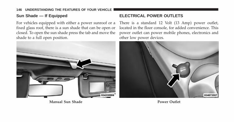
Sun Shade — If Equipped
For vehicles equipped with either a power sunroof or afixed glass roof, there is a sun shade that can be open orclosed. To open the sun shade press the tab and move theshade to a full open position.
ELECTRICAL POWER OUTLETS
There is a standard 12 Volt (13 Amp) power outlet,located in the floor console, for added convenience. Thispower outlet can power mobile phones, electronics andother low power devices.
Manual Sun Shade Power Outlet
146 UNDERSTANDING THE FEATURES OF YOUR VEHICLE
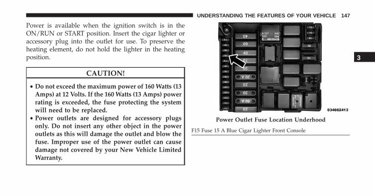
Power is available when the ignition switch is in theON/RUN or START position. Insert the cigar lighter oraccessory plug into the outlet for use. To preserve theheating element, do not hold the lighter in the heatingposition.
CAUTION!
• Do not exceed the maximum power of 160 Watts (13Amps) at 12 Volts. If the 160 Watts (13 Amps) powerrating is exceeded, the fuse protecting the systemwill need to be replaced.
• Power outlets are designed for accessory plugsonly. Do not insert any other object in the poweroutlets as this will damage the outlet and blow thefuse. Improper use of the power outlet can causedamage not covered by your New Vehicle LimitedWarranty.
Power Outlet Fuse Location Underhood
F15 Fuse 15 A Blue Cigar Lighter Front Console
3
UNDERSTANDING THE FEATURES OF YOUR VEHICLE 147

WARNING!
To avoid serious injury or death:• Only devices designed for use in this type of outlet
should be inserted into any 12 Volt outlet.• Do not touch with wet hands.• Close the lid when not in use and while driving the
vehicle.• If this outlet is mishandled, it may cause an electric
shock and failure.
CAUTION!
• Many accessories that can be plugged in drawpower from the vehicle’s battery, even when not inuse (i.e., cellular phones, etc.). Eventually, ifplugged in long enough, the vehicle’s battery will
(Continued)
CAUTION! (Continued)discharge sufficiently to degrade battery life and/orprevent the vehicle from starting.
• Accessories that draw higher power (i.e., coolers,vacuum cleaners, lights, etc.) will degrade the bat-tery even more quickly. Only use these intermit-tently and with great caution.
• After the use of high power draw accessories, orlong periods of the vehicle not being started (withaccessories still plugged in), the vehicle must beplugged in to recharge the vehicle’s battery.
148 UNDERSTANDING THE FEATURES OF YOUR VEHICLE

CIGAR LIGHTER — IF EQUIPPED
WARNING!
When the cigar lighter is in use it becomes very hot.To avoid serious injury, handle the cigar lighter withcare. Always check that the cigar lighter has turnedoff.
CUPHOLDERS
For the driver and front passenger, cupholders are lo-cated on the floor console between the front seats.
Front Cupholders
3
UNDERSTANDING THE FEATURES OF YOUR VEHICLE 149
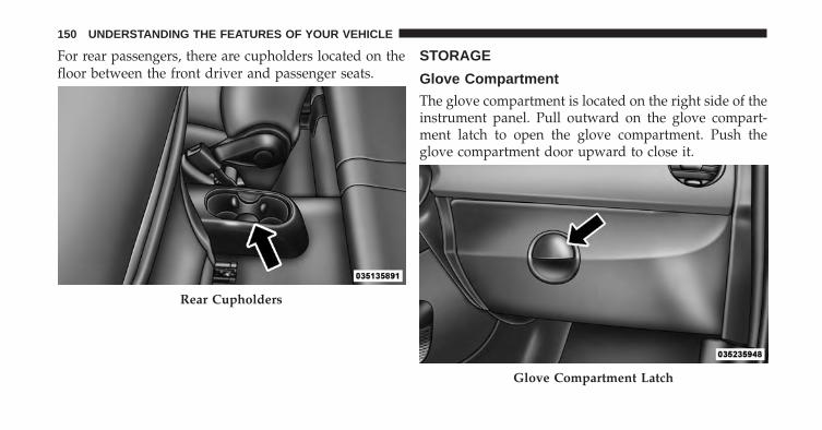
For rear passengers, there are cupholders located on thefloor between the front driver and passenger seats.
STORAGE
Glove Compartment
The glove compartment is located on the right side of theinstrument panel. Pull outward on the glove compart-ment latch to open the glove compartment. Push theglove compartment door upward to close it.
Rear Cupholders
Glove Compartment Latch
150 UNDERSTANDING THE FEATURES OF YOUR VEHICLE
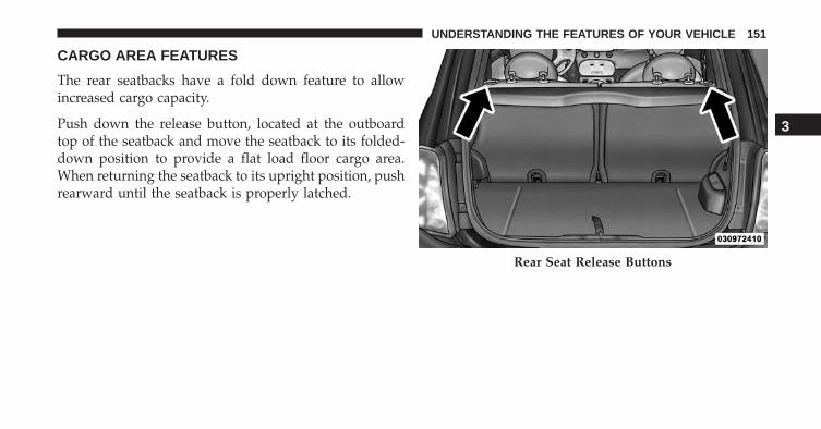
CARGO AREA FEATURES
The rear seatbacks have a fold down feature to allowincreased cargo capacity.
Push down the release button, located at the outboardtop of the seatback and move the seatback to its folded-down position to provide a flat load floor cargo area.When returning the seatback to its upright position, pushrearward until the seatback is properly latched.
Rear Seat Release Buttons
3
UNDERSTANDING THE FEATURES OF YOUR VEHICLE 151
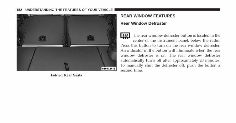
REAR WINDOW FEATURES
Rear Window Defroster
The rear window defroster button is located in thecenter of the instrument panel, below the radio.
Press this button to turn on the rear window defroster.An indicator in the button will illuminate when the rearwindow defroster is on. The rear window defrosterautomatically turns off after approximately 20 minutes.To manually shut the defroster off, push the button asecond time.
Folded Rear Seats
152 UNDERSTANDING THE FEATURES OF YOUR VEHICLE
CAUTION!
Failure to follow these cautions can cause damage tothe heating elements:• Use care when washing the inside of the rear
window. Do not use abrasive window cleaners onthe interior surface of the window. Use a soft clothand a mild washing solution, wiping parallel to theheating elements. Labels can be peeled off aftersoaking with warm water.
• Do not use scrapers, sharp instruments, or abrasivewindow cleaners on the interior surface of thewindow.
• Keep all objects a safe distance from the window.
3
UNDERSTANDING THE FEATURES OF YOUR VEHICLE 153

UNDERSTANDING YOUR INSTRUMENT PANEL
CONTENTS� INSTRUMENT PANEL FEATURES . . . . . . . . . .157
� INSTRUMENT CLUSTER . . . . . . . . . . . . . . . . .159
� INSTRUMENT CLUSTER DESCRIPTIONS . . . . .160
� ELECTRONIC VEHICLE INFORMATIONCENTER (EVIC) . . . . . . . . . . . . . . . . . . . . . . .168
▫ EVIC Control Buttons . . . . . . . . . . . . . . . . . .168
▫ Electronic Vehicle Information Center (EVIC)Setup Menu . . . . . . . . . . . . . . . . . . . . . . . . .169
▫ Trip Computer . . . . . . . . . . . . . . . . . . . . . . .171
� SALES CODE (RAB) RADIO . . . . . . . . . . . . . .174
▫ Introduction . . . . . . . . . . . . . . . . . . . . . . . . .174
▫ Suggestions. . . . . . . . . . . . . . . . . . . . . . . . . .174
▫ Technical Specifications . . . . . . . . . . . . . . . . .176
▫ Quick Guide . . . . . . . . . . . . . . . . . . . . . . . . .177
▫ General Information. . . . . . . . . . . . . . . . . . . .180
▫ Functions And Adjustments . . . . . . . . . . . . . .181
▫ Radio . . . . . . . . . . . . . . . . . . . . . . . . . . . . . .188
▫ SiriusXM Satellite Radio — If Equipped. . . . . .190
▫ CD Player . . . . . . . . . . . . . . . . . . . . . . . . . . .193
▫ CD MP3 Player . . . . . . . . . . . . . . . . . . . . . . .195
4

▫ Troubleshooting. . . . . . . . . . . . . . . . . . . . . . .198
� iPod®/USB/MEDIA PLAYER CONTROL —IF EQUIPPED . . . . . . . . . . . . . . . . . . . . . . . . .199
� STEERING WHEEL AUDIO CONTROLS . . . . . .200
▫ Radio Operation . . . . . . . . . . . . . . . . . . . . . .201
▫ CD Player Operation . . . . . . . . . . . . . . . . . . .201
▫ Operating Instructions — Hands-Free Phone(If Equipped). . . . . . . . . . . . . . . . . . . . . . . . .201
� CD/DVD DISC MAINTENANCE . . . . . . . . . . .201
� RADIO OPERATION AND MOBILE PHONES . .202
� CLIMATE CONTROLS . . . . . . . . . . . . . . . . . . .202
▫ Automatic Temperature Control (ATC) . . . . . .202
156 UNDERSTANDING YOUR INSTRUMENT PANEL
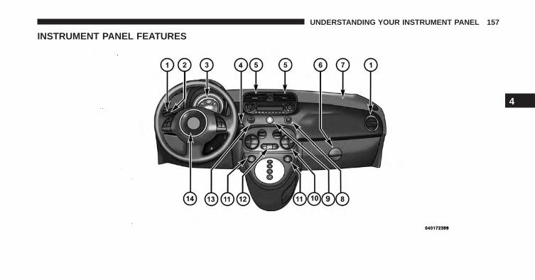
INSTRUMENT PANEL FEATURES
4
UNDERSTANDING YOUR INSTRUMENT PANEL 157

1 — Side Vent 6 — Storage Compartment 11 — Power Window Controls2 — Multifunction Lever – LightControl
7 — Passenger Air Bag 12 — Heated Seat Controls/FrontFog Light Control
3 — Instrument Cluster And Elec-tronic Vehicle Information Center
8 — Rear Defrost Button 13 — ESC Off
4 — Windshield Wiper, Washer,Trip Computer
9 — Hazard Button 14 — Horn/Driver Airbag
5 — Central Air Vents 10 — Climate Controls
158 UNDERSTANDING YOUR INSTRUMENT PANEL
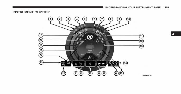
INSTRUMENT CLUSTER
4
UNDERSTANDING YOUR INSTRUMENT PANEL 159
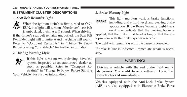
INSTRUMENT CLUSTER DESCRIPTIONS
1. Seat Belt Reminder Light
When the ignition switch is first turned to ON/RUN, this light will turn on if the driver’s seat beltis unbuckled, a chime will sound. When driving,
if the driver’s seat belt remains unbuckled, the Seat BeltReminder Light will illuminate and the chime will sound.Refer to “Occupant Restraints” in “Things To KnowBefore Starting Your Vehicle” for further information.
2. Air Bag Warning Light
If this light turns on while driving, have thesystem inspected at an authorized dealer assoon as possible. Refer to “Occupant Re-straints” in “Things To Know Before Starting
Your Vehicle” for further information.
3. Brake Warning Light
This light monitors various brake functions,including brake fluid level and parking brakeapplication. If the Brake Warning Light turnson it may indicate that the parking brake is
applied, that the brake fluid level is low, or that there isa problem with the brake system reservoir.
The light will remain on until the cause is corrected.
If brake failure is indicated, immediate repair is neces-sary.
WARNING!
Driving a vehicle with the red brake light on isdangerous. You could have a collision. Have thevehicle checked immediately.
Vehicles equipped with the Anti-Lock Brake System(ABS), are also equipped with Electronic Brake Force
160 UNDERSTANDING YOUR INSTRUMENT PANEL
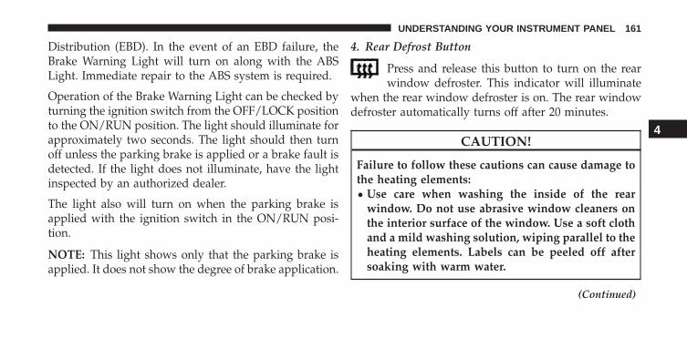
Distribution (EBD). In the event of an EBD failure, theBrake Warning Light will turn on along with the ABSLight. Immediate repair to the ABS system is required.
Operation of the Brake Warning Light can be checked byturning the ignition switch from the OFF/LOCK positionto the ON/RUN position. The light should illuminate forapproximately two seconds. The light should then turnoff unless the parking brake is applied or a brake fault isdetected. If the light does not illuminate, have the lightinspected by an authorized dealer.
The light also will turn on when the parking brake isapplied with the ignition switch in the ON/RUN posi-tion.
NOTE: This light shows only that the parking brake isapplied. It does not show the degree of brake application.
4. Rear Defrost Button
Press and release this button to turn on the rearwindow defroster. This indicator will illuminate
when the rear window defroster is on. The rear windowdefroster automatically turns off after 20 minutes.
CAUTION!
Failure to follow these cautions can cause damage tothe heating elements:• Use care when washing the inside of the rear
window. Do not use abrasive window cleaners onthe interior surface of the window. Use a soft clothand a mild washing solution, wiping parallel to theheating elements. Labels can be peeled off aftersoaking with warm water.
(Continued)
4
UNDERSTANDING YOUR INSTRUMENT PANEL 161
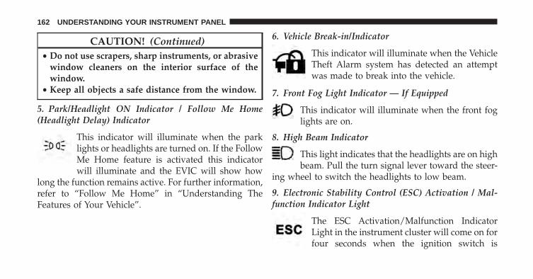
CAUTION! (Continued)• Do not use scrapers, sharp instruments, or abrasive
window cleaners on the interior surface of thewindow.
• Keep all objects a safe distance from the window.
5. Park/Headlight ON Indicator / Follow Me Home(Headlight Delay) Indicator
This indicator will illuminate when the parklights or headlights are turned on. If the FollowMe Home feature is activated this indicatorwill illuminate and the EVIC will show how
long the function remains active. For further information,refer to “Follow Me Home” in “Understanding TheFeatures of Your Vehicle”.
6. Vehicle Break-in/Indicator
This indicator will illuminate when the VehicleTheft Alarm system has detected an attemptwas made to break into the vehicle.
7. Front Fog Light Indicator — If Equipped
This indicator will illuminate when the front foglights are on.
8. High Beam Indicator
This light indicates that the headlights are on highbeam. Pull the turn signal lever toward the steer-
ing wheel to switch the headlights to low beam.
9. Electronic Stability Control (ESC) Activation / Mal-function Indicator Light
The ESC Activation/Malfunction IndicatorLight in the instrument cluster will come on forfour seconds when the ignition switch is
162 UNDERSTANDING YOUR INSTRUMENT PANEL
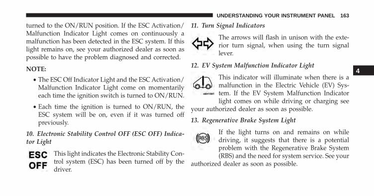
turned to the ON/RUN position. If the ESC Activation/Malfunction Indicator Light comes on continuously amalfunction has been detected in the ESC system. If thislight remains on, see your authorized dealer as soon aspossible to have the problem diagnosed and corrected.
NOTE:
• The ESC Off Indicator Light and the ESC Activation/Malfunction Indicator Light come on momentarilyeach time the ignition switch is turned to ON/RUN.
• Each time the ignition is turned to ON/RUN, theESC system will be on, even if it was turned offpreviously.
10. Electronic Stability Control OFF (ESC OFF) Indica-tor Light
This light indicates the Electronic Stability Con-trol system (ESC) has been turned off by thedriver.
11. Turn Signal Indicators
The arrows will flash in unison with the exte-rior turn signal, when using the turn signallever.
12. EV System Malfunction Indicator Light
This indicator will illuminate when there is amalfunction in the Electric Vehicle (EV) Sys-tem. If the EV System Malfunction Indicatorlight comes on while driving or charging see
your authorized dealer as soon as possible.
13. Regenerative Brake System Light
If the light turns on and remains on whiledriving, it suggests that there is a potentialproblem with the Regenerative Brake System(RBS) and the need for system service. See your
authorized dealer as soon as possible.
4
UNDERSTANDING YOUR INSTRUMENT PANEL 163

14. Door Ajar Lights
These lights will turn on to indicate when the drivers,passengers or both doors may be ajar.
15. Liftgate Ajar Light
This light will turn on to indicate when the liftgate maybe ajar.
16. Service Propulsion System Warning Light
The Service Propulsion System Warning Lightwill illuminate if there is a malfunction de-tected with the Propulsion System. If the lightcomes on or remains on while driving see your
authorized dealer.
17. Plugged In Indicator
This green indicator will illuminate when thevehicle is plugged in.
18. Plugged In Indicator
This red indicator will illuminate if there is amalfunction or interruption during the vehiclecharging process.
19. Icy Road Indicator
This light will illuminate during an icy roadcondition.
20. Electronic Speed Control SET
This light will turn on when the electronicspeed control is SET. For further information,refer to “Electronic Speed Control” in “Under-standing The Features Of Your Vehicle.”
164 UNDERSTANDING YOUR INSTRUMENT PANEL
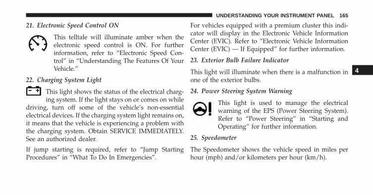
21. Electronic Speed Control ON
This telltale will illuminate amber when theelectronic speed control is ON. For furtherinformation, refer to “Electronic Speed Con-trol” in “Understanding The Features Of YourVehicle.”
22. Charging System Light
This light shows the status of the electrical charg-ing system. If the light stays on or comes on while
driving, turn off some of the vehicle’s non-essentialelectrical devices. If the charging system light remains on,it means that the vehicle is experiencing a problem withthe charging system. Obtain SERVICE IMMEDIATELY.See an authorized dealer.
If jump starting is required, refer to “Jump StartingProcedures” in “What To Do In Emergencies”.
For vehicles equipped with a premium cluster this indi-cator will display in the Electronic Vehicle InformationCenter (EVIC). Refer to ”Electronic Vehicle InformationCenter (EVIC) — If Equipped” for further information.
23. Exterior Bulb Failure Indicator
This light will illuminate when there is a malfunction inone of the exterior bulbs.
24. Power Steering System Warning
This light is used to manage the electricalwarning of the EPS (Power Steering System).Refer to “Power Steering” in “Starting andOperating” for further information.
25. Speedometer
The Speedometer shows the vehicle speed in miles perhour (mph) and/or kilometers per hour (km/h).
4
UNDERSTANDING YOUR INSTRUMENT PANEL 165
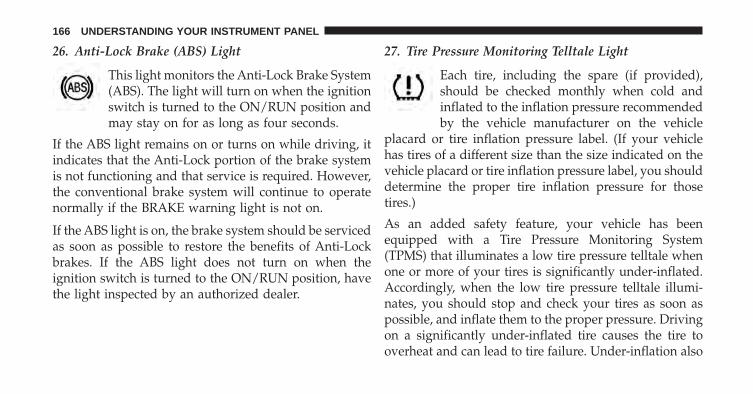
26. Anti-Lock Brake (ABS) Light
This light monitors the Anti-Lock Brake System(ABS). The light will turn on when the ignitionswitch is turned to the ON/RUN position andmay stay on for as long as four seconds.
If the ABS light remains on or turns on while driving, itindicates that the Anti-Lock portion of the brake systemis not functioning and that service is required. However,the conventional brake system will continue to operatenormally if the BRAKE warning light is not on.
If the ABS light is on, the brake system should be servicedas soon as possible to restore the benefits of Anti-Lockbrakes. If the ABS light does not turn on when theignition switch is turned to the ON/RUN position, havethe light inspected by an authorized dealer.
27. Tire Pressure Monitoring Telltale Light
Each tire, including the spare (if provided),should be checked monthly when cold andinflated to the inflation pressure recommendedby the vehicle manufacturer on the vehicle
placard or tire inflation pressure label. (If your vehiclehas tires of a different size than the size indicated on thevehicle placard or tire inflation pressure label, you shoulddetermine the proper tire inflation pressure for thosetires.)
As an added safety feature, your vehicle has beenequipped with a Tire Pressure Monitoring System(TPMS) that illuminates a low tire pressure telltale whenone or more of your tires is significantly under-inflated.Accordingly, when the low tire pressure telltale illumi-nates, you should stop and check your tires as soon aspossible, and inflate them to the proper pressure. Drivingon a significantly under-inflated tire causes the tire tooverheat and can lead to tire failure. Under-inflation also
166 UNDERSTANDING YOUR INSTRUMENT PANEL
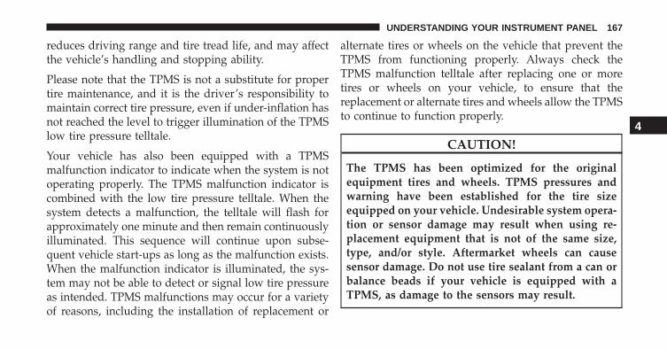
reduces driving range and tire tread life, and may affectthe vehicle’s handling and stopping ability.
Please note that the TPMS is not a substitute for propertire maintenance, and it is the driver’s responsibility tomaintain correct tire pressure, even if under-inflation hasnot reached the level to trigger illumination of the TPMSlow tire pressure telltale.
Your vehicle has also been equipped with a TPMSmalfunction indicator to indicate when the system is notoperating properly. The TPMS malfunction indicator iscombined with the low tire pressure telltale. When thesystem detects a malfunction, the telltale will flash forapproximately one minute and then remain continuouslyilluminated. This sequence will continue upon subse-quent vehicle start-ups as long as the malfunction exists.When the malfunction indicator is illuminated, the sys-tem may not be able to detect or signal low tire pressureas intended. TPMS malfunctions may occur for a varietyof reasons, including the installation of replacement or
alternate tires or wheels on the vehicle that prevent theTPMS from functioning properly. Always check theTPMS malfunction telltale after replacing one or moretires or wheels on your vehicle, to ensure that thereplacement or alternate tires and wheels allow the TPMSto continue to function properly.
CAUTION!
The TPMS has been optimized for the originalequipment tires and wheels. TPMS pressures andwarning have been established for the tire sizeequipped on your vehicle. Undesirable system opera-tion or sensor damage may result when using re-placement equipment that is not of the same size,type, and/or style. Aftermarket wheels can causesensor damage. Do not use tire sealant from a can orbalance beads if your vehicle is equipped with aTPMS, as damage to the sensors may result.
4
UNDERSTANDING YOUR INSTRUMENT PANEL 167
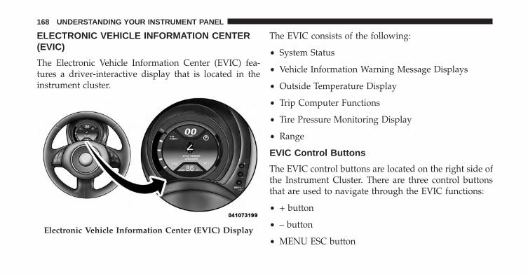
ELECTRONIC VEHICLE INFORMATION CENTER(EVIC)
The Electronic Vehicle Information Center (EVIC) fea-tures a driver-interactive display that is located in theinstrument cluster.
The EVIC consists of the following:
• System Status
• Vehicle Information Warning Message Displays
• Outside Temperature Display
• Trip Computer Functions
• Tire Pressure Monitoring Display
• Range
EVIC Control Buttons
The EVIC control buttons are located on the right side ofthe Instrument Cluster. There are three control buttonsthat are used to navigate through the EVIC functions:
• + button
• – button
• MENU ESC buttonElectronic Vehicle Information Center (EVIC) Display
168 UNDERSTANDING YOUR INSTRUMENT PANEL

Press the MENU ESC button briefly to access the menuand/or go to next screen or to confirm the required menuoption. Press and hold the MENU ESC button (approxi-mately one second) to return to the main screen.
Press the + button to scroll upward through the dis-played menu and the related options or to increase the
displayed value. Press the – button to scroll downwardthrough the displayed menu and the related options or todecrease the value displayed.
+ and – buttons activate different functions according tothe following situations:
• To scroll the menu options upwards or downwards.
• To increase or decrease values during settings.
When opening one of the front doors, the EVIC displaywill come on and information such as odometer andclock will be displayed.
Electronic Vehicle Information Center (EVIC)Setup Menu
The menu comprises a series of functions arranged in acycle. Press the + and – buttons to access the differentoptions and settings (setup).
EVIC Control Buttons
4
UNDERSTANDING YOUR INSTRUMENT PANEL 169
The setup menu can be activated by pressing the MENUESC button. Single presses on the + or – buttons willscroll through the setup menu options. The menu in-cludes the following functions:
• Charging Schedule
• Set Date
• Set Time
• Units
• Languages
• Battery % Display
• Auto Door Lock
• Remote Unlock
• Daytime Running Lights
• Button Volume
• Hill Start Assist
• Stored Warnings
• Tutorial
• Connectivity ID
• Restore Factory Settings
• Exit Menu
Selecting An Option Of The Main Menu WithoutSubmenu:
1. Briefly press the MENU ESC button to select the mainmenu option to set.
2. Press the + or – button (by single presses) to select thenew setting.
3. Briefly press the MENU ESC button to store the newsetting and go back to the main menu option previ-ously selected.
170 UNDERSTANDING YOUR INSTRUMENT PANEL
Selecting An Option Of The Main Menu With Sub-menu:
1. Briefly press the MENU ESC button to display the firstsubmenu option.
2. Press the + or – button (by single presses) to scrollthrough all the submenu options.
3. Briefly press the MENU ESC button to select thedisplayed submenu option and to open the relevantsetup menu.
4. Press the + or – button (by single presses) to select thenew setting for this submenu option.
5. Briefly press the MENU ESC button to store the newsetting and go back to the previously selected sub-menu option.
6. Press and hold the MENU ESC button to return to themain menu (short hold) or the main screen (longerhold).
Trip Computer
The Trip Computer is located in the instrument cluster.The Trip Computer displays trip information such as:average speed, distance traveled, average energy, timetraveled, motor power, and tire pressure.
Trip Button
The TRIP button, located on the right steering columnstalk.
4
UNDERSTANDING YOUR INSTRUMENT PANEL 171
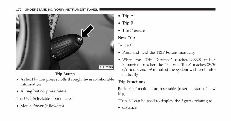
• A short button press scrolls through the user-selectableinformation.
• A long button press resets.
The User-Selectable options are:
• Motor Power (Kilowatts)
• Trip A
• Trip B
• Tire Pressure
New Trip
To reset:
• Press and hold the TRIP button manually.
• When the “Trip Distance” reaches 9999.9 miles/kilometers or when the “Elapsed Time” reaches 29.59(29 hours and 59 minutes) the system will reset auto-matically.
Trip Functions
Both trip functions are resettable (reset — start of newtrip).
“Trip A” can be used to display the figures relating to:
• distance
Trip Button
172 UNDERSTANDING YOUR INSTRUMENT PANEL
• avg. energy
• avg. speed
• elapsed time (driving time).
“Trip B” can be used to display the figures relating to:
• distance
• avg. energy
• avg. speed
• elapsed time (driving time).
Values Displayed
Range
This indicates the distance which may be travelled withthe remaining battery charge, assuming that drivingconditions will not change. The message “----” willappear when the system is initializing.
NOTE: The range depends on several factors: drivingstyle, type of route (freeway, residential, mountain roads,etc.), conditions of use of the car (load, tire pressure, etc.).Trip planning must take into account the above notes.
Distance Traveled
This value shows the distance covered since the last reset.
Average Speed
This value shows the vehicle’s average speed as a func-tion of the overall time elapsed since the last reset.
Elapsed Time
This value shows the time elapsed since the last reset.
4
UNDERSTANDING YOUR INSTRUMENT PANEL 173

SALES CODE (RAB) RADIO
Introduction
The radio has been designed according to the specifica-tions of the passenger compartment, with a personalizeddesign to match the style of the dashboard.
If the radio has BLUE&ME™, refer to the appropriate“BLUE&ME™ User’s Manual” for further information.
The instructions for use are given below and we recom-mend you to read them carefully.
Suggestions
Road Safety
Please, learn how to use all different radio functions (e.g.store stations) before beginning to drive.
Reception Conditions
Reception conditions change constantly while driving.Reception may be interfered with by the presence ofmountains, buildings or bridges, or when you are faraway from the broadcaster.
RAB Radio
174 UNDERSTANDING YOUR INSTRUMENT PANEL

WARNING!
Having the volume turned up high can cause thedriver to not be able to hear important traffic sounds,i.e. sirens, horns, etc. Failure to hear traffic soundsand other important audible information can resultin serious injury or death. Always adjust the volumeso that you can still hear background noises.
Care And Maintenance
Clean the cover with a soft antistatic cloth only. Cleaningand polishing products could damage the surface.
CDs
The presence of dirt, scratches or distortions on the CDscould cause skipping and poor sound quality while it isplaying. For optimal playback conditions, follow theseguidelines:
• Only use branded CDs.
• Clean every CD thoroughly removing any fingermarks or dust using a soft cloth. Hold CDs by theoutside and clean them from the middle outwards.
• Never use chemicals (e.g. antistatics or thinners orsprays) for cleaning as they could damage the surfaceof the CDs.
• After listening to them place CDs back in their boxes toprevent them from being damaged.
• Do not expose CDs to direct sunlight, high tempera-tures or moisture for long periods.
• Do not stick labels on the CD surface or write on therecorded surface with pencils or pens.
• Do not use CDs that are very scratched, flawed,distorted, etc. Using discs like these will result inmalfunctions or damage to the player.
4
UNDERSTANDING YOUR INSTRUMENT PANEL 175
• The use of original CD media is required for the bestquality audio production. Correct operation is notguaranteed when CD-R/RW media are used that werenot correctly burned and/or with a maximum capacityabove 650 Mb.
• Do not use commercially available protective sheetsfor CDs or discs, with stabilizers, etc. as they could getstuck in the internal mechanism and damage the disc.
• If a copy-protected CD is used, it may take a fewseconds before the system starts to play it. The CDplayer cannot be guaranteed to play all protecteddiscs. The fact that the CD is protected from beingcopied is often shown in very small letters or isdifficult to read on the actual CD cover where it maybe, for example, “COPY CONTROL,” “COPY PRO-TECTED,” “THIS CD CANNOT BE PLAYED ON APC/MAC.”
• The CD player is capable of reading most compressionsystems currently in use, following the development ofthese systems, the reading of all compression formatsis not guaranteed.
Technical Specifications
The complete system consists of:
• Two 165 mm diameter midwoofer speakers, onespeaker in each of the front doors.
• Two 22 mm diameter tweeter speakers, one speaker ineach of the front pillars.
• Two 100 mm diameter full range speakers, one speakerin each of the rear side panels.
• Antenna on the car roof.
• Radio with CD/MP3 player.
176 UNDERSTANDING YOUR INSTRUMENT PANEL

With Alpine Premium Audio system (if equipped):
• Two 165 mm diameter midwoofer speakers.
• Two 11 mm tweeter speakers in the front pillars.
• Two 100 mm full range speakers, one speaker in eachof the rear side panels.
• An amplifier in the trunk on the right-hand side panel.
• Antenna on the car roof.
• Radio with CD/MP3 player.
With BEATS Premium Audio system (if equipped):
• A subwoofer in the trunk on the left-hand side panel.Quick Guide
Radio Controls
BUTTON GENERAL FUNCTIONS MODEOn Short button pressOff Short button press
TUNER AM, FM, SAT (if equipped) source selection Short repeated button pressA-B-C Cycles A, B, C presets for AM, FM, SAT
(if equipped)Short repeated button press
MEDIA CD/AUX/Media Player(if equipped and present) source selection
Short repeated button press
4
UNDERSTANDING YOUR INSTRUMENT PANEL 177
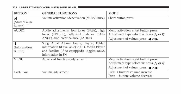
BUTTON GENERAL FUNCTIONS MODE
(Mute/PauseButton)
Volume activation/deactivation (Mute/Pause) Short button press
AUDIO Audio adjustments: low tones (BASS), hightones (TREBLE), left/right balance (BAL-ANCE), front/rear balance (FADER)
Menu activation: short button pressAdjustment type selection: press orAdjustment of values: press or
(InformationButton)
Song, Artist, Album, Genre, Playlist, Folderinformation (if available) in CD, Media Playerand Satellite (if so equipped); Toggles RBDSinformation in FM
MENU Advanced functions adjustment Menu activation: short button pressAdjustment type selection: press orAdjustment of values: press or
+Vol/–Vol Volume adjustment Press + button: volume increasePress – button: volume decrease
178 UNDERSTANDING YOUR INSTRUMENT PANEL

BUTTON RADIO FUNCTIONS MODERadio Station Search:• Automatic Search• Manual Search
Automatic search: press buttons or (longpress for fast forward)Manual search: press buttons or (longpress for fast forward)
1 2 3 4 5 Current radio station storing Long button press for memory preset 1 to 5respectively
Stored station recall Short button press for memory preset 1 to 5respectively
BUTTON CD FUNCTIONS MODECD ejection Short button pressPrevious/next track play Short button press orCD track fast forward/rewind Long button press orPrevious/next folder play (for CD-MP3) Short button press or
4
UNDERSTANDING YOUR INSTRUMENT PANEL 179
General Information
The radio offers the following functions:
Radio Section
• PLL tuning with FM/AM bands
• RBDS (Radio Broadcast Data System)
• Automatic/manual station tuning
• FM Multipath detector
• Manual storing of 25 stations (base radio) and 40stations (if equipped with Satellite): 15 on FM band(5 on FMA, 5 on FMB, 5 on FMC), 10 on AM band (5 onAMA, 5 on AMB), 15 on Satellite Band - if equipped(5 on SATA, 5 on SATB, 5 on SATC)
• SPEED VOLUME function: Customer selectable auto-matic volume adjustment depending on the car speed
• Automatic Stereo/Mono selection
CD Section
• Track selection (forward/backward)
• Fast forward/rewind through tracks
• CD Display function: display of track number and onmp3 discs (song title, artist) and time elapsed sincestart of the track
• Playing Audio CD, CD-R and CD-RW
WARNING!
On multimedia CDs, besides audio tracks, there aredata tracks too. Playing this type of CD could causehissing at a volume that could jeopardize road safetyas well as causing damage to the speakers.
180 UNDERSTANDING YOUR INSTRUMENT PANEL

CD/MP3 Section
• MP3-Info function (ID3-TAG)
• Folder selection (previous/next)
• Track selection (forward/backward)
• Fast forward/rewind through tracks
• MP3 Display function: display of folder name, ID3-TAG information, time elapsed since the start of thetrack, name of the file
• Playing audio or data CD, CD-R and CD-RW
Audio Section
• Mute/pause function
• Soft mute function
• Loudness function
• Graphic 7 band equalizer (if equipped)
• Separate bass/treble tone adjustment
• Right/left channel balancing
• Front/rear fader
Functions And Adjustments
Turning The Car Radio On
The car radio comes on when the (ON/OFF) buttonis pressed briefly.
When the car radio is turned on and the on volume limitis on, the volume is limited to a setting of five even if ithad been set higher when previously used.
Turning The Car Radio Off
Press the (ON/OFF) button to turn the radio off.
4
UNDERSTANDING YOUR INSTRUMENT PANEL 181

Selecting The Radio Functions
By pressing the TUNER button briefly and repeatedly,the following audio sources can be selected cyclically:
• AM, FM and Satellite Bands (if equipped)
Selecting The CD Function
By briefly pressing the MEDIA button, the CD audiosource can be selected (only if a CD is loaded).
Volume Adjustment
To adjust the volume, press the buttons +Vol or –Vol toincrease/decrease the volume.
Mute/Pause Function
Press the button briefly to activate the MUTE func-tion. The volume will gradually decrease and thewording “TUNER Mute” will be shown on the display(in radio mode) or “CD Pause” (in CD mode).
Press the button again to deactivate the MUTEfunction. The volume will gradually increase until itreaches the previously set level.
When the volume level is changed using the dedicatedcontrols, the Mute function is deactivated and the vol-ume is adjusted to the new level selected.
Audio Adjustment
The functions that can be selected from the audio menuchange depending on the context: AM/FM/MEDIA/SATELLITE.
Press the AUDIO button briefly to change the Audiofunctions. After the AUDIO button is first pressed, thedisplay will show the Bass level value for the sourceactivated at that time (e.g. in FM mode the display willshow the wording “FM Bass +2”).
182 UNDERSTANDING YOUR INSTRUMENT PANEL
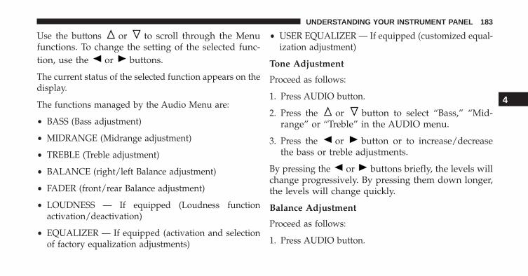
Use the buttons or to scroll through the Menufunctions. To change the setting of the selected func-tion, use the or buttons.
The current status of the selected function appears on thedisplay.
The functions managed by the Audio Menu are:
• BASS (Bass adjustment)
• MIDRANGE (Midrange adjustment)
• TREBLE (Treble adjustment)
• BALANCE (right/left Balance adjustment)
• FADER (front/rear Balance adjustment)
• LOUDNESS — If equipped (Loudness functionactivation/deactivation)
• EQUALIZER — If equipped (activation and selectionof factory equalization adjustments)
• USER EQUALIZER — If equipped (customized equal-ization adjustment)
Tone Adjustment
Proceed as follows:
1. Press AUDIO button.
2. Press the or button to select “Bass,” “Mid-range” or “Treble” in the AUDIO menu.
3. Press the or button or to increase/decreasethe bass or treble adjustments.
By pressing the or buttons briefly, the levels willchange progressively. By pressing them down longer,the levels will change quickly.
Balance Adjustment
Proceed as follows:
1. Press AUDIO button.
4
UNDERSTANDING YOUR INSTRUMENT PANEL 183
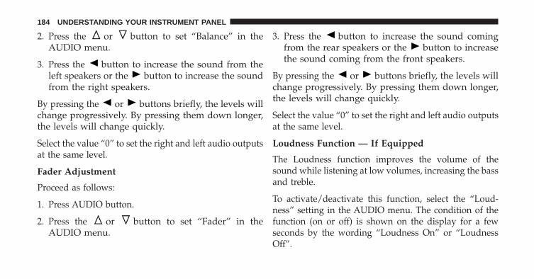
2. Press the or button to set “Balance” in theAUDIO menu.
3. Press the button to increase the sound from theleft speakers or the button to increase the soundfrom the right speakers.
By pressing the or buttons briefly, the levels willchange progressively. By pressing them down longer,the levels will change quickly.
Select the value “0” to set the right and left audio outputsat the same level.
Fader Adjustment
Proceed as follows:
1. Press AUDIO button.
2. Press the or button to set “Fader” in theAUDIO menu.
3. Press the button to increase the sound comingfrom the rear speakers or the button to increasethe sound coming from the front speakers.
By pressing the or buttons briefly, the levels willchange progressively. By pressing them down longer,the levels will change quickly.
Select the value “0” to set the right and left audio outputsat the same level.
Loudness Function — If Equipped
The Loudness function improves the volume of thesound while listening at low volumes, increasing the bassand treble.
To activate/deactivate this function, select the “Loud-ness” setting in the AUDIO menu. The condition of thefunction (on or off) is shown on the display for a fewseconds by the wording “Loudness On” or “LoudnessOff”.
184 UNDERSTANDING YOUR INSTRUMENT PANEL

Preset/User/Classic/Rock/Jazz Functions — IfEquipped
The built-in equalizer can be activated/deactivated.When the equalizer function is off, the audio settings canonly be changed by adjusting the “Bass” and “Treble”settings, whereas when the function is on, the acousticcurves can be adjusted. To deactivate the equalizer, selectthe “EQ Preset” function in the audio menu.
To activate the equalizer, use the AUDIO button or toselect one of the adjustments:• “EQ User” (adjustment of 7 equalizer bands that can
be changed by the user)• “Classic” (equalizer preset for optimal classic music
sound)• “Rock” (equalizer preset for optimal rock and pop
music sound)• “Jazz” (equalizer preset for optimal jazz music sound)
When one of the equalizer adjustments is activated thewording “EQ” lights up.
User EQ Settings Function — If Equipped
To set a personalized equalizer adjustment:
1. Press AUDIO button.
2. Use the or buttons to set EQ function.
3. Use or buttons to select �EQ User.�
4. Press MENU button to start adjusting equalizer.
5. On the display a seven bar graph will appear, in whicheach bar represents a frequency. Select the bar to beadjusted by using the or buttons. The selectedbar will start to flash and it can be adjusted using
or buttons.
6. To store the setting, press the MENU or AUDIObuttons.
4
UNDERSTANDING YOUR INSTRUMENT PANEL 185

Menu
MENU Button Functions
Press the MENU button briefly to activate the Menufunction.
Use the or buttons to scroll through the menufunctions. To change the setting of the selected func-tion, use the or buttons.
The current status of the selected function appears on thedisplay.
The functions managed by the Menu are:
• Speech Volume
• Aux Audio Offset
• Radio Off
• Sat ID
• SiriusXM Telephone Number
• System Reset
• Speed Volume
• On Volume Limit
Press the MENU button again to exit the Menu function.
Speed Volume Function — If Equipped
This function automatically adapts the volume level tothe speed of the car, turning up the volume when thespeed increases to maintain the ratio with the noise levelinside the passenger compartment. To activate/deactivate the function, use the buttons. The wording“Speed volume” appears on the display, followed by thecurrent status of the function:
• Off: function deactivated
• Low: function activated (low sensitivity)
186 UNDERSTANDING YOUR INSTRUMENT PANEL
• High: function activated (high sensitivity)
On Volume Limit
This function makes it possible to activate/deactivate themaximum volume limit when turning the radio on.
The display shows the function status:
• “On volume limit: on” – when the radio is turned onthe volume level will be:– If the volume level is equal to or higher than the
maximum value, the radio will come on at themaximum volume.
– If the volume level is between the minimum andmaximum values, the radio will come on at thesame volume as before it was switched off.
– If the volume level is equal to or lower than theminimum value, the radio will come on at theminimum volume.
• “On volume limit: off” – The radio will come on at thesame volume as before it was switched off. Thevolume level can be between 0 and 40.
Use the buttons or to change the setting.
NOTE:
• Using the Menu it is only possible to adjust theactivation/deactivation of the function and not theminimum or maximum volume value.
• If the battery charge is too low, the volume cannot beadjusted between the minimum and the maximumlevel.
4
UNDERSTANDING YOUR INSTRUMENT PANEL 187
Radio Off Function
This function makes it possible to set the radio switchingoff mode by choosing between two methods.
The chosen mode appears on the display:
• “Radio off: 00 min” — The radio turns off in connec-tion with the ignition key; the radio is turned auto-matically off as soon as the key is turned to the STOPposition.
• “Radio off: 20 min” — The radio turns off indepen-dently from the ignition key; the radio remains on fora maximum period of 20 minutes after the key hasbeen turned to the STOP position.
System Reset Function
This function is used to restore all settings to the factoryvalues. The options are:
• NO — No restore intervention.
• YES — The default parameters will be restored. Dur-ing such operation, the wording “Resetting” appearson the display. At the end of the operation, the sourcedoes not change and the previous situation will bedisplayed.
Radio
(Tuner) Introduction
When the car radio is turned on, the last function thatwas selected before turning it off (Radio, CD, CD MP3,AUX) is activated.
To select the Radio function when another audio source isbeing listened to, briefly press the TUNER button.
Once the Radio mode has been activated, the display willshow the name (RBDS stations only) or the frequency ofthe selected radio station, the frequency band selected(e.g. FMA) and the preset button number (e.g. P1).
188 UNDERSTANDING YOUR INSTRUMENT PANEL
Frequency Band Selection
With the Radio mode active, press the FM or AM tunerbutton briefly and repeatedly to select the desired recep-tion band.
Each time the button is pressed the following bands areselected cyclically:
• AM, FM or SAT (if equipped)
Each band is highlighted by the corresponding wordingson the display. The radio will be tuned to last stationselected on the respective frequency band.
Preset Buttons
The buttons numbered from 1 to 5 are used to set thefollowing pre-selections:
• 15 in the FM band (5 in FMA, 5 in FMB, 5 in FMC
• 10 in the AM band (5 in AMA, 5 in AMB)
• 15 in SAT (if so equipped) (5 SATA, 5 SATB, 5 SATC)
To listen to a preset station, select the desired frequencyband and then briefly press the corresponding presetbutton (from 1 to 5).
By pressing the preset button for more than 2 seconds,the tuned station will be stored. Pressing the A-B-Cbutton will change between the preset memory group inthe current frequency band.
Automatic Tuning
Briefly press the or button to start the automatictuning search for the next station that can be receivedin the selected direction.
If the or button is pressed for longer, the rapidsearch is started. When the button is released, thetuner will stop on the next station that can be received.
4
UNDERSTANDING YOUR INSTRUMENT PANEL 189

Manual Tuning
This is used to manually search for stations in thepreselected band.
Select the desired frequency band and then press brieflyand repeatedly the or button to start the search inthe desired direction. If the or button is pressedlonger, the fast search starts and then stops when thebutton is released.
Stereophonic Broadcasters
If the incoming signal is weak, the reproduction isautomatically switched from Stereo to Mono.
SiriusXM Satellite Radio — If Equipped
SiriusXM Satellite Radio
With over 130 channels, SiriusXM Satellite Radio bringsyou more of what you love. Get 69 channels of 100%commercial-free music, plus all of your favorite sports,
news, talk and entertainment. Hear every NFL game,every NASCAR race, college sports and more. The big-gest and most compelling names in talk with HowardStern and Martha Stewart, laugh-out-loud comedy withJamie Foxx’s The Foxxhole and Blue Collar Comedy, pluskids’ programming, world-class news, local traffic andweather. All of this with crystal clear, coast-to-coastcoverage. Everything worth listening to is now onSiriusXM. A one-year SiriusXM Satellite Radio subscrip-tion is included. SiriusXM and all related marks andlogos are trademarks of SiriusXM Radio Inc. and itssubsidiaries. SiriusXM Radio requires a subscription,sold separately after trial subscription included withvehicle purchase. Prices and programming are providedby SiriusXM and are subject to change. Subscriptionsgoverned by Terms & Conditions available atsirius.com/service terms. SiriusXM Radio U.S. serviceonly available to those at least 18 years of age in the 48contiguous United States, D.C., and PR. Service availablein Canada; see www.siriuscanada.ca.
190 UNDERSTANDING YOUR INSTRUMENT PANEL

SiriusXM Satellite Radio Program Types
Program Types can be selected by pressing the orbuttons. The Program Type will change to the next
category and the radio will then tune to first station inthat program type. Pressing or buttons will tuneto only the stations in that program type.
Pressing the or buttons until �All� is displayedwill allow normal tuning to all stations.
The Program Types available are: All, Pop, Rock,Electronic/Dance, Hip-Hop/R&B, Country, Christian,Jazz/Standards, Classical, Latin/World, Sports, Enter-tainment, Talk, News, NPR, Comedy, Family & Health,Religion, Traffic/Weather.
You can find the SiriusXM current terms and conditionsat http://www.sirius.com.
Re-Subscribe To SiriusXM Satellite Radio
New vehicle purchasers or lessees will receive a freelimited time subscription to SiriusXM Satellite Radiowith their radio. Following expiration of the free services,it will be necessary to access the information on theSubscription Information screen in order to re-subscribe.Press the UP/DOWN button to scroll through the MenuFunctions, and the Left/Right button to change theselected Set-up Menu function.
Write down the Electronic Serial Number (ESN) for yourreceiver. To retrieve the Electronic Serial Number ofSiriusXM Satellite Receiver Module tune to Channel 0.Make sure that when the order is placed, the ESN arecorrect. If any of the ESN numbers are not enteredcorrectly, then the SiriusXM subscription will not be ableto be transferred to the new radio and will not be active
4
UNDERSTANDING YOUR INSTRUMENT PANEL 191

when installed in the customer’s vehicle. To reactivateyour service, either call the number listed on the displayor visit the provider online.
CAUTION!
Neither SIRIUS nor FIAT is responsible for anyerrors in accuracies in the SIRIUS data services or itsuse in vehicles.
SiriusXM and all related marks and logos are trademarksof SiriusXM Radio Inc. and its subsidiaries. SiriusXMRadio requires a subscription, sold separately after trialsubscription included with vehicle purchase. Prices andprogramming are provided by SiriusXM and are subjectto change. Subscriptions governed by Terms & Condi-tions available at sirius.com/service terms. SiriusXMRadio U.S. service only available to those at least 18 yearsof age in the 48 contiguous United States, D.C., & PR.Visit www.sirius.com
Sirius Subscription Issues When Replacing ASirius Radio
When a radio needs to be replaced, the dealer will needthe SIRIUS information to order a new radio (even if theSIRIUS subscription has lapsed). The ESN number con-tains 12 digits.
The following are instructions for retrieving the Elec-tronic Serial Number (ESN) from FIAT 500 NAFTA modelradios:
To retrieve the ESN of SIRIUS Satellite Receiver Moduletune to Channel 0. Make sure that when the order isplaced, the ESN are correct. If any of the ESN numbersare not entered correctly, then the SIRIUS subscriptionwill not be able to be transferred to the new radio andwill not be active when installed in the customer’svehicle.
192 UNDERSTANDING YOUR INSTRUMENT PANEL

Satellite Radio Antenna — If Equipped
The antenna for the satellite radio is mounted on the roofof the vehicle. Do not place items on the roof around theroof top antenna location. Objects placed within the lineof sight of the antenna will cause decreased performance.Larger luggage items should be placed as far from theantenna as possible. Do not place items directly on orabove the antenna.
CD Player
Introduction
This chapter describes the operation of the CD playeronly. To operate the radio, refer to the description in the“Functions and Adjustments” chapter.
CD Player Selection
To activate the CD player built into the equipment,proceed as follows:
• Load a CD with the equipment switched on. The firsttrack will start to play.
or
• If a CD has already been loaded, turn on the radio andthen briefly press the MEDIA button to select the “CD”function mode. The last track listened to will start toplay.
It is advisable to use original CDs to ensure optimalplaying. If CD-R/RWs are used, we recommend usinggood quality media that are burned at the slowest speedpossible.
CD Loading/Ejecting
To load the CD, insert it gently into the slot to activate themotorized loading system, which will position it correctly.
The CD can be loaded with the radio off and the ignitionkey turned to ON/RUN. In this case, the radio will
4
UNDERSTANDING YOUR INSTRUMENT PANEL 193

remain off. When the radio is turned on, the last sourcelistened to before being switched off, will be activated.
When a CD is inserted, the display will show the symbol“CD” and the wording “CD Reading.” They will remaindisplayed for the whole time required for the radio toread the CD. When this time has elapsed the radioautomatically starts playing the first track.
Press the button with the radio turned on, toactivate the motorized CD ejection system. After ejec-tion, the last audio source listened to before playingthe CD will be heard.
If the CD is not removed from the radio, it will automati-cally be reloaded about 20 seconds later but will notresume playing until the �MEDIA� button is pressed toselect the CD mode. The radio will switch to the lastsource prior to CD mode.
The CD cannot be ejected if the radio is off.
Possible Error Messages
If the loaded CD cannot be read (e.g. a CD ROM has beeninserted or the CD is inserted the wrong way or there isa reading error) the display shows the wording “CD Discerror.”
The CD will then be ejected and the audio sourceactivated before the CD mode selection will be heard.
A CD which cannot be read will not be ejected until thesefunctions are over. At the end, with the CD modeactivated, the display will show the wording “CD Discerror” for a few seconds and then the CD will be ejected.
Display Information
When the CD player is operating, information will ap-pear on the display with the following meaning:
• “Track 5” indicates the CD track number.
194 UNDERSTANDING YOUR INSTRUMENT PANEL

• “03:42” indicates the time elapsed since the start of thetrack (if the relevant Menu function is activated).
Track Selection
Briefly press the button to play the previous CDtrack and the button to play the next track. Thetracks are selected cyclically: the first track is selectedafter the last track and vice versa.
If the track has been played for more than 3 seconds,pressing the button, starts the track again from thebeginning. In this case, if you want to play theprevious track, press the button twice consecu-tively.
Track Fast Forward/Rewind
Keep the button pressed down to fast forward theselected track and keep the button pressed down tofast rewind the track. The fast forward/rewind willstop once the button is released.
Pause Function
To pause the CD player, press the button. The word-ing “CD Pause” appears on the display.
To resume listening to the track, press the buttonagain.
CD MP3 Player
Introduction
This chapter describes the operation of the CD MP3player.
NOTE: Layer-3 audio decoding technology is licensedfrom Fraunhofer IIS and Thomson multimedia.
MP3 Mode
In addition to playing regular audio CDs, the radio is alsoenabled to play CDROMs on which compressed audiofiles have been recorded in an MP3 format.
4
UNDERSTANDING YOUR INSTRUMENT PANEL 195

To guarantee optimal reproduction, it is advisable to usegood quality CDs burned at the lowest speed possible.
The files on an MP3 CD are structured in folders thatcreate lists of all the folders containing MP3 tracks(folders or subfolders are all on the same level). Thefolders that do not contain MP3 tracks cannot be selected.
The specifications and operating conditions for playingMP3 files are the following:
• The CD-ROMs used should be burned in accordancewith ISO standard 9660.
• The music files should have the extension “.mp3” or“.wma” files with a different extension will not bereproduced.
• The sampling frequencies that can be reproduced are:44.1 kHz, stereo (from 96 to 320 kbit/s) – 22.05 kHz,mono or stereo (from 32 to 80 kbit/s).
• Tracks with a variable bit-rate can be reproduced.
NOTE: The track names must not include the followingcharacters: spaces, ‘ (apostrophes), ( and ) (open and closebrackets). During the burning of a MP3 CD, make surethat the names of the files do not contain these characters;if not, the radio will not be able to play the tracksinvolved.
Selecting MP3 Sessions With Hybrid Discs
If a hybrid disc is inserted (Mixed Mode, Enhanced,CD-Extra) also containing MP3 files, the radio automati-cally starts playing the audio session. It is possible tomove to the MP3 session while playing by keeping theCD button pressed for more than two seconds.
196 UNDERSTANDING YOUR INSTRUMENT PANEL
NOTE: When the function is activated the radio may takea few seconds to start playing. While checking the discthe display will show “CD Reading.” If no MP3 files aredetected, the radio will resume playing the audio sessionfrom the point where it was interrupted.
Display Information
ID3–Tag Information Display
In addition to the information relating to the timeelapsed, folder name and file name, the radio is alsocapable of displaying ID3–TAG information relating toTitle Track, Artist and Author.
When one of the ID3-TAG pieces of information is chosento be displayed (Title, Artist, Album) and this informa-tion has not been recorded for the track played, the text�UNKNOWN� will be displayed for that field.
Selection Of Next/Previous Folder
Press the button to select a next folder or thebutton to select the previous folder. The display
will show the number of the folder.
The folders are selected cyclically. The first folder isselected after the last folder and vice versa.
If no other folder/track is selected in the next twoseconds, the first track on the new folder will be played.
After the last track in a folder is played, the next folderwill be played.
Structure Of The Folders
The radio with MP3 player:
• Recognizes only the folders that effectively containMP3 format files.
4
UNDERSTANDING YOUR INSTRUMENT PANEL 197

• If the MP3 files on a CD-ROM are structured insub-folders their structure is compressed to a singlelevel structure, where the sub-folders are taken to thelevel of the main folders.
Troubleshooting
General
Sound Volume Low
The Fader function should be adjusted to the values “F”(front) only to prevent the reduction in radio outputpower and the cancelling of the volume if the Fader leveladjustment is equal to R+9.
Source Can Not Be Selected
Nothing has been loaded. Load the CD or the MP3 CD tobe listened to.
CD Player
The CD Does Not Play:
The CD is dirty. Clean the CD.
The CD is scratched. Try using another CD.
The CD Can Not Be Loaded:
A CD is already loaded. Press the button and removethe CD.
MP3 File Reading
Track Skips While Playing Mp3 Files:
The CD is scratched or dirty.
The Duration Of The Mp3 Tracks Is Not CorrectlyDisplayed:
In some cases (due to the recording mode) the duration ofthe MP3 tracks can be displayed incorrectly.
198 UNDERSTANDING YOUR INSTRUMENT PANEL
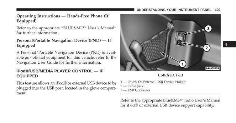
Operating Instructions — Hands-Free Phone (IfEquipped)
Refer to the appropriate “BLUE&ME™ User’s Manual”for further information.
Personal/Portable Navigation Device (PND) — IfEquipped
A Personal/Portable Navigation Device (PND) is avail-able as optional equipment for this vehicle, refer to theNavigation User Guide for further information.
iPod®/USB/MEDIA PLAYER CONTROL — IFEQUIPPED
This feature allows an iPod® or external USB device to beplugged into the USB port, located in the glove compart-ment.
Refer to the appropriate Blue&Me™ radio User’s Manualfor iPod® or external USB device support capability.
USB/AUX Port
1 — iPod® Or External USB Device Holder2 — Cable Jack3 — USB Connector
4
UNDERSTANDING YOUR INSTRUMENT PANEL 199
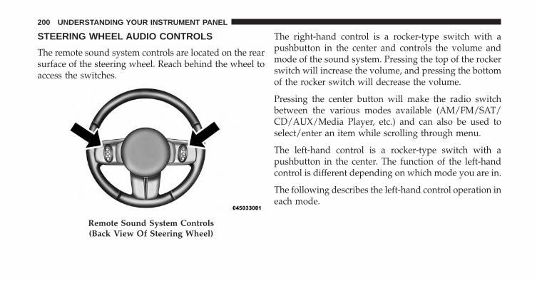
STEERING WHEEL AUDIO CONTROLS
The remote sound system controls are located on the rearsurface of the steering wheel. Reach behind the wheel toaccess the switches.
The right-hand control is a rocker-type switch with apushbutton in the center and controls the volume andmode of the sound system. Pressing the top of the rockerswitch will increase the volume, and pressing the bottomof the rocker switch will decrease the volume.
Pressing the center button will make the radio switchbetween the various modes available (AM/FM/SAT/CD/AUX/Media Player, etc.) and can also be used toselect/enter an item while scrolling through menu.
The left-hand control is a rocker-type switch with apushbutton in the center. The function of the left-handcontrol is different depending on which mode you are in.
The following describes the left-hand control operation ineach mode.
Remote Sound System Controls(Back View Of Steering Wheel)
200 UNDERSTANDING YOUR INSTRUMENT PANEL
Radio Operation
Pressing the top of the switch will “Seek” up for the nextlistenable station and pressing the bottom of the switchwill “Seek” down for the next listenable station.
The button located in the center of the left-hand controlwill tune to the next preset station that you have pro-grammed in the radio preset pushbutton.
CD Player Operation
Pressing the top of the switch once will go to the nexttrack on the CD. Pressing the bottom of the switch oncewill go to the beginning of the current track, or to thebeginning of the previous track if it is within one secondafter the current track begins to play.
If you press the switch up or down twice, it plays thesecond track; three times, it will play the third, etc.
Operating Instructions — Hands-Free Phone(If Equipped)
Refer to the appropriate Blue&Me™ User’s Manual forfurther information.
CD/DVD DISC MAINTENANCE
To keep a CD/DVD in good condition, take the followingprecautions:
1. Handle the disc by its edge; avoid touching thesurface.
2. If the disc is stained, clean the surface with a soft cloth,wiping from center to edge.
3. Do not apply paper or tape to the disc; avoid scratch-ing the disc.
4. Do not use solvents such as benzene, thinner, cleaners,or anti-static sprays.
4
UNDERSTANDING YOUR INSTRUMENT PANEL 201
5. Store the disc in its case after playing.
6. Do not expose the disc to direct sunlight.
7. Do not store the disc where temperatures may becometoo high.
NOTE: If you experience difficulty in playing a particulardisc, it may be damaged (e.g., scratched, reflective coat-ing removed, a hair, moisture or dew on the disc)oversized, or have protection encoding. Try a knowngood disc before considering disc player service.
RADIO OPERATION AND MOBILE PHONES
Under certain conditions, the mobile phone being on inyour vehicle can cause erratic or noisy performance fromyour radio. This condition may be lessened or eliminatedby relocating the mobile phone antenna. This condition isnot harmful to the radio. If your radio performance doesnot satisfactorily “clear” by the repositioning of the
antenna, it is recommended that the radio volume beturned down or off during mobile phone operation.
CLIMATE CONTROLS
The air conditioning and heating system is designed tomake you comfortable in all types of weather.
Automatic Temperature Control (ATC)
• The Automatic Temperature Control (ATC) allows theoccupant to select a comfort settings.
• The system provides set-and-forget operation for op-timum comfort and convenience.
• The system can be controlled manually, if desired.
The ATC system automatically maintains the interiorcomfort level desired by the occupant.
202 UNDERSTANDING YOUR INSTRUMENT PANEL
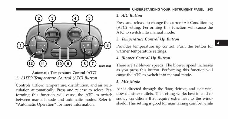
1. AUTO Temperature Control (ATC) Button
Controls airflow, temperature, distribution, and air recir-culation automatically. Press and release to select. Per-forming this function will cause the ATC to switchbetween manual mode and automatic modes. Refer to“Automatic Operation” for more information.
2. A/C Button
Press and release to change the current Air Conditioning(A/C) setting. Performing this function will cause theATC to switch into manual mode.
3. Temperature Control Up Button
Provides temperature up control. Push the button forwarmer temperature settings.
4. Blower Control Up Button
There are 12 blower speeds. The blower speed increasesas you press this button. Performing this function willcause the ATC to switch into manual mode.
5. Mix Mode
Air is directed through the floor, defrost, and side win-dow demister outlets. This setting works best in cold orsnowy conditions that require extra heat to the wind-shield. This setting is good for maintaining comfort while
Automatic Temperature Control (ATC)
4
UNDERSTANDING YOUR INSTRUMENT PANEL 203

reducing moisture on the windshield. Performing thisfunction will cause the ATC to switch into manual mode.
6. Front Defrost
Press and release to change the current setting. Theindicator illuminates when ON. The blower will auto-matically default to medium-high if the Defrost mode isselected. Performing this function will cause the ATC toswitch into manual mode.
7. Floor Mode
Air is directed through the floor outlets with a smallamount flowing through the defrost and side windowdemister outlets. Performing this function will cause theATC to switch into manual mode.
8. Panel Mode
Air is directed through the outlets in the instrumentpanel. These outlets can be adjusted to direct airflow.Performing this function will cause the ATC to switchinto manual mode.
NOTE: The center instrument panel outlets can be aimedso that they are directed toward the rear seat passengersfor maximum airflow to the rear.
9. Blower Control Down Button
There are 12 blower speeds. The blower speed decreasesas you press this button. Performing this function willcause the ATC to switch into manual mode.
10. Temperature Control Down Button
Provides temperature down control. Push the button forcooler temperature settings.
204 UNDERSTANDING YOUR INSTRUMENT PANEL

11. Climate Control ON/OFF Button
Press and release to turn the Climate Control ON or OFF.
12. Recirculation Control Button
Press and release to change the current setting. Theindicator illuminates when ON.
NOTE:
• When in Defrost mode, the Recirculation button willflash if pressed. This indicates that you can notproceed to this mode due to fogging risk.
• When the Auto indicator is on and the Recirculationindicator is off, the Recirculation is in AUTO mode. Ifthe Recirculation indicator is on, the Recirculationsetting is manual and Recirculation is on.
Automatic Operation
1. Press the AUTO button on the Automatic TemperatureControl (ATC) Panel, the indicator will illuminatewhen on.
2. Next, adjust the temperature you would like thesystem to maintain by adjusting the temperature con-trol buttons. Once the desired temperature is dis-played, the system will achieve and automaticallymaintain that comfort level.
3. When the system is set up for your comfort level, it isnot necessary to change the settings. You will experi-ence the greatest efficiency by simply allowing thesystem to function automatically.
4
UNDERSTANDING YOUR INSTRUMENT PANEL 205
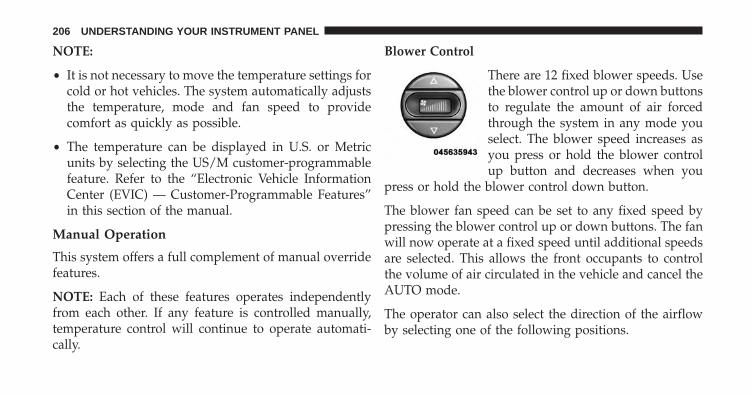
NOTE:
• It is not necessary to move the temperature settings forcold or hot vehicles. The system automatically adjuststhe temperature, mode and fan speed to providecomfort as quickly as possible.
• The temperature can be displayed in U.S. or Metricunits by selecting the US/M customer-programmablefeature. Refer to the “Electronic Vehicle InformationCenter (EVIC) — Customer-Programmable Features”in this section of the manual.
Manual Operation
This system offers a full complement of manual overridefeatures.
NOTE: Each of these features operates independentlyfrom each other. If any feature is controlled manually,temperature control will continue to operate automati-cally.
Blower Control
There are 12 fixed blower speeds. Usethe blower control up or down buttonsto regulate the amount of air forcedthrough the system in any mode youselect. The blower speed increases asyou press or hold the blower controlup button and decreases when you
press or hold the blower control down button.
The blower fan speed can be set to any fixed speed bypressing the blower control up or down buttons. The fanwill now operate at a fixed speed until additional speedsare selected. This allows the front occupants to controlthe volume of air circulated in the vehicle and cancel theAUTO mode.
The operator can also select the direction of the airflowby selecting one of the following positions.
206 UNDERSTANDING YOUR INSTRUMENT PANEL

Panel Mode
Air comes from the outlets in the instrumentpanel. Each of these outlets can be individually
adjusted to direct the flow of air. The air vanes of thecenter outlets and outboard outlets can be moved up anddown or side to side to regulate airflow direction. Thereis a shut off wheel located below the air vanes to shut offor adjust the amount of airflow from these outlets.
Floor Mode
Air comes from the floor outlets. A slight amountof air is directed through the defrost and side
window demister outlets.
Bi-Level
Air is directed through the panel and floor outlets.Press and release the Panel mode button and Floor
mode button to enter Bi-Level mode, the indicatorsilluminate when ON. Performing this function will causethe ATC to switch into manual mode.
Mix Mode
Air comes from the floor, defrost and side windowdemister outlets. This mode works best in cold or
snowy conditions. It allows you to stay comfortablewhile keeping the windshield clear.
Defrost Mode
Air comes from the windshield and side windowdemister outlets. Use Defrost mode with maxi-
mum temperature settings for best windshield and sidewindow defrosting. When the defrost mode is selected,the blower will automatically default to medium-high.
4
UNDERSTANDING YOUR INSTRUMENT PANEL 207
Air Conditioning (A/C)
The Air Conditioning (A/C) button allows the operatorto manually activate or deactivate the air conditioningsystem. When in A/C mode with the ATC set to a cooltemperature, dehumidified air flows through the airoutlets. If Economy mode is desired, press the A/Cbutton to turn off the A/C mode in the ATC display anddeactivate the A/C system.
NOTE:
• If the system is in Mix or Defrost Mode, the A/C canbe turned off, but the A/C system shall remain activeto prevent fogging of the windows.
• If fog or mist appears on the windshield or side glass,select Defrost mode and increase blower speed.
Recirculation Control
When outside air contains smoke, odors, or highhumidity, or if rapid cooling is desired, you maywish to recirculate interior air by pressing the
RECIRCULATION control button. Recirculation modeshould only be used temporarily. The recirculation LEDwill illuminate when this button is selected. Push thebutton a second time to turn off the Recirculation modeLED and allow outside air into the vehicle.
NOTE: In cold weather, use of Recirculation mode maylead to excessive window fogging. The recirculationfeature may be unavailable (indicator light shall blink) ifconditions exist that could create fogging on the inside ofthe windshield. On systems with Manual Climate Con-trols, the Recirculation mode is not allowed in Defrost
208 UNDERSTANDING YOUR INSTRUMENT PANEL
mode to improve window clearing operation. Recircula-tion will be disabled automatically if this mode is se-lected. Attempting to use Recirculation while in thismode will cause the LED in the control button to blinkand then turn off.
Operating Tips
Window Fogging
Windows will fog on the inside when the humidity insidethe vehicle is high. This often occurs in mild or cooltemperatures when it’s rainy or humid. In most cases,turning the air conditioning (pressing the A/C button) onwill clear the fog. Adjust the temperature control, airdirection, and blower speed to maintain comfort.
As the temperature gets colder, it may be necessary todirect air onto the windshield. Adjust the temperaturecontrol and blower speed to maintain comfort. Higher
blower speeds will reduce fogging. Interior fogging onthe windshield can be quickly removed by selecting theDefrost mode.
Regular cleaning of the inside of the windows with anon-filming cleaning solution (vinegar and water worksvery well) will help prevent contaminates (cigarettesmoke, perfumes, etc.) from sticking to the windows.Contaminates increase the rate of window fogging.
NOTE: Automatic Temperature Controls (ATC) will au-tomatically adjust the climate control settings to reduceor eliminate window fogging on the front windshield.When this occurs, recirculation will be unavailable.
Summer Operation
NOTE: In some cases during high temperature opera-tion, the air conditioning system performance may bereduced. This is to help protect the vehicle from over-heating during the high load condition.
4
UNDERSTANDING YOUR INSTRUMENT PANEL 209
Your air conditioning system is also equipped with anautomatic recirculation system. When the system sensesa heavy load or high heat conditions, it may use Recir-culation A/C mode to provide additional comfort whilein automatic mode.
Winter Operation
When operating the system during the winter months,make sure the air intake, located directly in front of thewindshield, is free of ice, slush, snow, or other obstruc-tions.
Vacation Storage
Anytime you store your vehicle, or keep it out of service(i.e., vacation) for two weeks or more, run the airconditioning system at idle for about five minutes in thefresh air using the high blower setting. This will ensureadequate system lubrication to minimize the possibilityof compressor damage when the air conditioning systemis started again.
210 UNDERSTANDING YOUR INSTRUMENT PANEL

STARTING AND OPERATING
CONTENTS� STARTING PROCEDURES . . . . . . . . . . . . . . . .214
▫ Single-Speed Transmission . . . . . . . . . . . . . . .214
▫ Normal Starting. . . . . . . . . . . . . . . . . . . . . . .214
� SINGLE–SPEED TRANSMISSION . . . . . . . . . . .215
▫ Key Ignition Park Interlock. . . . . . . . . . . . . . .217
▫ Gear Ranges . . . . . . . . . . . . . . . . . . . . . . . . .218
▫ Auto Park . . . . . . . . . . . . . . . . . . . . . . . . . . .220
� DRIVING ON SLIPPERY SURFACES . . . . . . . . .222
▫ Acceleration . . . . . . . . . . . . . . . . . . . . . . . . .222
▫ Traction . . . . . . . . . . . . . . . . . . . . . . . . . . . .222
� DRIVING THROUGH WATER . . . . . . . . . . . . .223
▫ Flowing/Rising Water . . . . . . . . . . . . . . . . . .223
▫ Shallow Standing Water . . . . . . . . . . . . . . . . .223
� POWER STEERING . . . . . . . . . . . . . . . . . . . . .224
� PARKING BRAKE . . . . . . . . . . . . . . . . . . . . . .226
� BRAKE SYSTEM . . . . . . . . . . . . . . . . . . . . . . .228
▫ Four-Wheel Anti-Lock Brake System (ABS) . . .228
� ELECTRONIC BRAKE CONTROL SYSTEM . . . .229
▫ Anti-Lock Brake System (ABS) . . . . . . . . . . . .229
▫ Brake Assist System (BAS) . . . . . . . . . . . . . . .230
5
▫ Traction Control System (TCS) . . . . . . . . . . . .230
▫ Electronic Stability Control (ESC) . . . . . . . . . .231
▫ ESC Activation/Malfunction Indicator LightAnd ESC OFF Indicator Light . . . . . . . . . . . .233
▫ Regenerative Braking . . . . . . . . . . . . . . . . . . .234
� TIRE SAFETY INFORMATION . . . . . . . . . . . . .235
▫ Tire Markings . . . . . . . . . . . . . . . . . . . . . . . .235
▫ Tire Identification Number (TIN). . . . . . . . . . .239
▫ Tire Terminology And Definitions . . . . . . . . . .240
▫ Tire Loading And Tire Pressure . . . . . . . . . . .242
� TIRES — GENERAL INFORMATION . . . . . . . .246
▫ Tire Pressure . . . . . . . . . . . . . . . . . . . . . . . .246
▫ Tire Inflation Pressures . . . . . . . . . . . . . . . . .247
▫ Tire Pressures For High Speed Operation . . . .249
▫ Radial Ply Tires . . . . . . . . . . . . . . . . . . . . . .249
▫ Tire Types . . . . . . . . . . . . . . . . . . . . . . . . . . .250
▫ Run Flat Tires — If Equipped . . . . . . . . . . . . .251
▫ Spare Tires — If Equipped . . . . . . . . . . . . . . .252
▫ Tire Spinning . . . . . . . . . . . . . . . . . . . . . . . .254
▫ Tread Wear Indicators . . . . . . . . . . . . . . . . . .255
▫ Life Of Tire . . . . . . . . . . . . . . . . . . . . . . . . .255
▫ Replacement Tires . . . . . . . . . . . . . . . . . . . . .256
� TIRE CHAINS (TRACTION DEVICES) . . . . . . . .257
� TIRE ROTATION RECOMMENDATIONS . . . . .259
� PREMIUM TIRE PRESSURE MONITORSYSTEM . . . . . . . . . . . . . . . . . . . . . . . . . . . . .260
212 STARTING AND OPERATING
▫ Premium TPM System . . . . . . . . . . . . . . . . . .262
▫ Tire Pressure Monitoring Low PressureWarnings . . . . . . . . . . . . . . . . . . . . . . . . . . .263
▫ TPMS Warning . . . . . . . . . . . . . . . . . . . . . . .264
▫ General Information. . . . . . . . . . . . . . . . . . . .266
� TRAILER TOWING . . . . . . . . . . . . . . . . . . . . .266
� RECREATIONAL TOWING (BEHINDMOTORHOME, ETC.) . . . . . . . . . . . . . . . . . . .266
▫ Towing This Vehicle Behind Another Vehicle . .266
� EXTENDING YOUR DRIVING RANGE PERCHARGE. . . . . . . . . . . . . . . . . . . . . . . . . . . . .267
▫ Driver Behavior Gauge. . . . . . . . . . . . . . . . . .268
▫ Range Projection . . . . . . . . . . . . . . . . . . . . . .269
5
STARTING AND OPERATING 213
STARTING PROCEDURES
Before starting your vehicle, adjust your seat, adjust bothinside and outside mirrors, and fasten your seat belts.
WARNING!
• Never leave children alone in a vehicle, or withaccess to an unlocked vehicle.
• Allowing children to be in a vehicle unattended isdangerous for a number of reasons. A child orothers could be seriously or fatally injured. Chil-dren should be warned not to touch the parkingbrake, brake pedal or the shift lever.
• Do not leave the Key Fob in or near the vehicle (orin a location accessible to children). A child couldoperate power windows, other controls, or movethe vehicle.
Single-Speed Transmission
The transmission must be in the PARK or NEUTRALposition before you can start the vehicle. Apply thebrakes when selecting a transmission gear from Park.
NOTE: You must press the brake pedal before selectinga transmission gear.
Normal Starting
Turn the key to the START position while your vehicle isin PARK. When the ignition key is turned to the STARTand then released to the RUN position, a chime willsound and the “READY” indicator in the EVIC willilluminate to indicate the 500e’s Electric Drive System hasstarted. When the “READY” indicator is illuminatedyour 500e is ready to be driven.
214 STARTING AND OPERATING

NOTE:
• If the key is held in the START position for more than10 seconds “READY” mode will not be achieved.Return the key to OFF position, and then back to theSTART position and hold for less than 10 seconds toachieve “READY”.
• If the “READY” indicator fails to illuminate after youhave followed the normal starting procedure contactyour authorized dealer.
SINGLE–SPEED TRANSMISSION
Your 500e uses a Single-Speed Transmission to direct theoutput from the electric motor. The single-speed trans-mission is operated using push-buttons instead of atraditional shift lever.
“READY” Indicator
5
STARTING AND OPERATING 215
The push-buttons are located on the lower instrumentpanel.
CAUTION!
Damage to the transmission may occur if the follow-ing precautions are not observed:• Place the transmission into PARK only after the
vehicle has come to a complete stop.• Place the transmission into or out of REVERSE
only after the vehicle has come to a complete stop.• Before placing the transmission into any range
make sure your foot is firmly pressing the brakepedal.
NOTE:
• You must press and hold the brake pedal whileshifting out of PARK.
• If all push-button LEDs are on when the key is ON, seeyour authorized dealer.
Single-Speed Transmission Push-Buttons
216 STARTING AND OPERATING

WARNING!
• Only place the transmission into gear when yourfoot is firmly pressing the brake pedal.
• Unintended movement of a vehicle could injurethose in or near the vehicle. As with all vehicles,you should never exit a vehicle while the vehicle isin “READY” mode. Before exiting a vehicle, alwaysapply the parking brake, shift the transmissioninto PARK, and remove the ignition key. Once thekey is removed, the transmission is locked inPARK, securing the vehicle against unwantedmovement.
• When leaving the vehicle, always remove the igni-tion key and lock your vehicle.
• Never leave children alone in a vehicle, or withaccess to an unlocked vehicle. Allowing children tobe in a vehicle unattended is dangerous for a
(Continued)
WARNING! (Continued)number of reasons. A child or others could beseriously or fatally injured. Children should bewarned not to touch the parking brake, brake pedalor the transmission range buttons.
• Do not leave the ignition key in or near the vehicle(or in a location accessible to children). A childcould operate power windows, other controls, ormove the vehicle.
Key Ignition Park Interlock
This vehicle is equipped with a Key Ignition Park Inter-lock which requires the transmission to be in PARKbefore the ignition switch can be turned to the OFFposition. The key can only be removed from the ignitionwhen the ignition is in the OFF position, and onceremoved, the transmission is locked in PARK.
5
STARTING AND OPERATING 217
Gear Ranges
Gear ranges are engaged by pressing one of the push-buttons.
NOTE:
• The brake pedal must be depressed to select a trans-mission gear range.
• After selecting any gear range, wait a moment to allowthe selected gear to engage before accelerating.
PARK (P)
This range supplements the parking brake by locking thetransmission. The vehicle can be started in this range.Never attempt to use PARK while the vehicle is inmotion. Apply the parking brake when leaving thevehicle in this range.
When parking on a level surface, you may place thetransmission into PARK first, and then apply the parkingbrake.
When parking on a hill, apply the parking brake beforeplacing the transmission into PARK. As an added pre-caution, turn the front wheels toward the curb on adownhill grade and away from the curb on an uphillgrade.
NOTE: Refer to the transmission range position dis-played on the EVIC and verify that it indicates the PARKposition.
WARNING!
• Never use the PARK position as a substitute for theparking brake. Always apply the parking brake
(Continued)
218 STARTING AND OPERATING
WARNING! (Continued)fully when parked to guard against vehicle move-ment and possible injury or damage.
• Your vehicle could move and injure you and othersif it is not in PARK. Make sure the transmission isin PARK before leaving the vehicle.
• It is dangerous to shift out of PARK or NEUTRALif your foot is not firmly pressing the brake pedal.The vehicle could accelerate quickly forward or inreverse. You could lose control of the vehicle andhit someone or something. Only shift the transmis-sion into gear when your foot is firmly pressing thebrake pedal.
• Unintended movement of a vehicle could injurethose in or near the vehicle. As with all vehicles, youshould never exit a vehicle while the vehicle is in“ready mode”. Before exiting a vehicle, always apply
(Continued)
WARNING! (Continued)the parking brake, shift the transmission into PARK,and remove the ignition key. Once the key is re-moved, the transmission is locked in PARK, securingthe vehicle against unwanted movement.
• When leaving the vehicle, always remove the igni-tion key and lock your vehicle.
• Never leave children alone in a vehicle, or withaccess to an unlocked vehicle. Allowing children tobe in a vehicle unattended is dangerous for anumber of reasons. A child or others could beseriously or fatally injured. Children should bewarned not to touch the parking brake, brake pedalor the transmission range buttons.
• Do not leave the ignition key in or near the vehicle(or in a location accessible to children). A childcould operate power windows, other controls, ormove the vehicle.
5
STARTING AND OPERATING 219

REVERSE (R)
This gear range is for moving the vehicle backward. Shiftinto REVERSE only after the vehicle has come to acomplete stop.
NEUTRAL (N)
The vehicle may be started in this gear range. Apply theparking brake and place the transmission into PARK ifyou must leave the vehicle.
WARNING!
Do not coast in NEUTRAL and never turn off theignition to coast down a hill. These are unsafepractices that limit your response to changing trafficor road conditions. You might lose control of thevehicle and have a collision.
CAUTION!
Towing the vehicle, coasting, or driving for any otherreason with the transmission in NEUTRAL can causesevere transmission damage. Refer to “RecreationalTowing” in “Starting And Operating” and “Towing ADisabled Vehicle” in “What To Do In Emergencies”for further information.
DRIVE (D)
Use this gear range for all city and highway driving.
Auto Park
The Auto Park feature automatically places the transmis-sion into PARK if there is any indication that the drivermay leave the vehicle while the transmission is in D(DRIVE), N (NEUTRAL) or R (REVERSE).
220 STARTING AND OPERATING
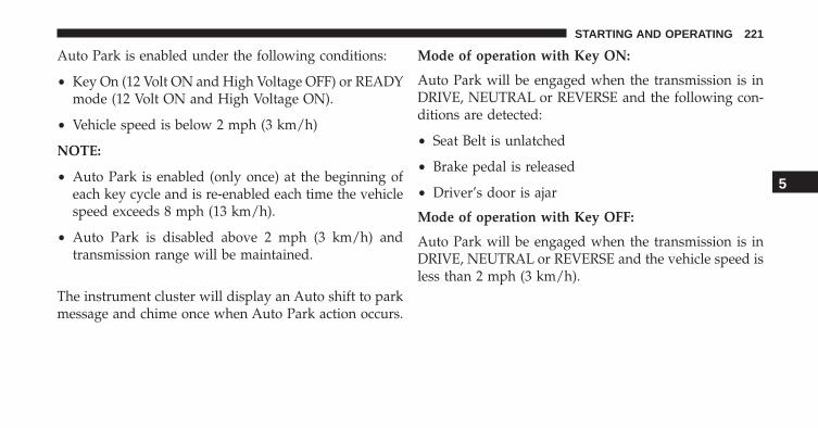
Auto Park is enabled under the following conditions:
• Key On (12 Volt ON and High Voltage OFF) or READYmode (12 Volt ON and High Voltage ON).
• Vehicle speed is below 2 mph (3 km/h)
NOTE:
• Auto Park is enabled (only once) at the beginning ofeach key cycle and is re-enabled each time the vehiclespeed exceeds 8 mph (13 km/h).
• Auto Park is disabled above 2 mph (3 km/h) andtransmission range will be maintained.
The instrument cluster will display an Auto shift to parkmessage and chime once when Auto Park action occurs.
Mode of operation with Key ON:
Auto Park will be engaged when the transmission is inDRIVE, NEUTRAL or REVERSE and the following con-ditions are detected:
• Seat Belt is unlatched
• Brake pedal is released
• Driver’s door is ajar
Mode of operation with Key OFF:
Auto Park will be engaged when the transmission is inDRIVE, NEUTRAL or REVERSE and the vehicle speed isless than 2 mph (3 km/h).
5
STARTING AND OPERATING 221
DRIVING ON SLIPPERY SURFACES
Acceleration
Rapid acceleration on snow covered, wet, or other slip-pery surfaces may cause the driving wheels to pullerratically to the right or left. This phenomenon occurswhen there is a difference in the surface traction underthe front (driving) wheels.
WARNING!
Rapid acceleration on slippery surfaces is dangerous.Unequal traction can cause sudden pulling of thefront wheels. You could lose control of the vehicleand possibly have a collision. Accelerate slowly andcarefully whenever there is likely to be poor traction(ice, snow, wet, mud, loose sand, etc.).
Traction
When driving on wet or slushy roads, it is possible for awedge of water to build up between the tire and roadsurface. This is hydroplaning and may cause partial orcomplete loss of vehicle control and stopping ability. Toreduce this possibility, the following precautions shouldbe observed:
1. Slow down during rainstorms or when the roads areslushy.
2. Slow down if the road has standing water or puddles.
3. Replace the tires when tread wear indicators firstbecome visible.
4. Keep tires properly inflated.
5. Maintain sufficient distance between your vehicle andthe vehicle in front of you to avoid a collision in asudden stop.
222 STARTING AND OPERATING
DRIVING THROUGH WATER
Driving through water more than a few inches/centimeters deep will require extra caution to ensuresafety and prevent damage to your vehicle.
Flowing/Rising Water
WARNING!
Do not drive on or across a road or path where wateris flowing and/or rising (as in storm run-off). Flow-ing water can wear away the road or path’s surfaceand cause your vehicle to sink into deeper water.Furthermore, flowing and/or rising water can carryyour vehicle away swiftly. Failure to follow thiswarning may result in injuries that are serious orfatal to you, your passengers, and others around you.
Shallow Standing Water
Although your vehicle is capable of driving throughshallow standing water, consider the following Cautionand Warning before doing so.
CAUTION!
• Always check the depth of the standing waterbefore driving through it. Never drive throughstanding water that is deeper than the bottom ofthe tire rims mounted on the vehicle.
• Determine the condition of the road or the paththat is under water and if there are any obstacles inthe way before driving through the standing water.
• Do not exceed 5 mph (8 km/h) when drivingthrough standing water. This will minimize waveeffects.
(Continued)
5
STARTING AND OPERATING 223

CAUTION! (Continued)• Driving through standing water may cause damage
to your vehicle’s drivetrain components. Alwaysinspect your vehicle’s fluids (i.e., transmission,coolant, etc.) for signs of contamination (i.e., fluidthat is milky or foamy in appearance) after drivingthrough standing water. Do not continue to operatethe vehicle if any fluid appears contaminated, asthis may result in further damage. Such damage isnot covered by the New Vehicle Limited Warranty.
• Driving through standing water limits your vehi-cle’s traction capabilities. Do not exceed 5 mph(8 km/h) when driving through standing water.
• Driving through standing water limits your vehi-cle’s braking capabilities, which increases stopping
(Continued)
CAUTION! (Continued)distances. Therefore, after driving through stand-ing water, drive slowly and lightly press on thebrake pedal several times to dry the brakes.
• Failure to follow these warnings may result ininjuries that are serious or fatal to you, your pas-sengers, and others around you.
POWER STEERING
The electric power steering system will give you goodvehicle response and increased ease of maneuverabilityin tight spaces. The system will vary its assist to providelight efforts while parking and good feel while driving. Ifthe electric steering system experiences a fault thatprevents it from providing assist, you will still have theability to steer the vehicle manually.
224 STARTING AND OPERATING

WARNING!
Continued operation with reduced or no power steer-ing assist could pose a safety risk to yourself andothers. Service should be obtained as soon as pos-sible.
If the Steering icon is flashing, it indicates that the vehicleneeds to be taken to an authorized dealer for service. It islikely the vehicle has lost power steering assistance.
If the Steering icon is displayed and the “POWER STEER-ING SYSTEM OVER TEMP” message is displayed on theEVIC screen, they indicate that extreme steering maneu-vers may have occurred which caused an over tempera-ture condition in the power steering system. Once driv-ing conditions are safe, pull over and let the vehicle idlefor a few moments until the icon and message turn off.
Refer to “Electronic Vehicle Information (EVIC)” in “Un-derstanding Your Instrument Panel” for further informa-tion.
If the Steering icon is displayed and the “SERVICEPOWER STEERING – ASSIST OFF” message is displayedthe EVIC screen, they indicate the vehicle needs to betaken to an authorized dealer for service. Refer to “Elec-tronic Vehicle Information (EVIC)” in “UnderstandingYour Instrument Panel” for further information.
NOTE:
• Even if the power steering assistance is no longeroperational, it is still possible to steer the vehicle.Under these conditions there will be a substantialincrease in steering effort, especially at low speeds andduring parking maneuvers.
• If the condition persists, see your authorized dealer forservice.
5
STARTING AND OPERATING 225
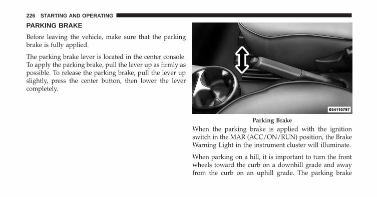
PARKING BRAKE
Before leaving the vehicle, make sure that the parkingbrake is fully applied.
The parking brake lever is located in the center console.To apply the parking brake, pull the lever up as firmly aspossible. To release the parking brake, pull the lever upslightly, press the center button, then lower the levercompletely.
When the parking brake is applied with the ignitionswitch in the MAR (ACC/ON/RUN) position, the BrakeWarning Light in the instrument cluster will illuminate.
When parking on a hill, it is important to turn the frontwheels toward the curb on a downhill grade and awayfrom the curb on an uphill grade. The parking brake
Parking Brake
226 STARTING AND OPERATING
should always be applied whenever the driver is not inthe vehicle.
WARNING!
• Never leave children alone in a vehicle, or withaccess to an unlocked vehicle.
• Allowing children to be in a vehicle unattended isdangerous for a number of reasons. A child orothers could be seriously or fatally injured. Chil-dren should be warned not to touch the parkingbrake, brake pedal or the transmission push but-tons.
• Do not leave the key fob in or near the vehicle (orin a location accessible to children), and do notleave the ignition in the MAR (ACC/ON/RUN)position. A child could operate power windows,other controls, or move the vehicle.
(Continued)
WARNING! (Continued)• Be sure the parking brake is fully disengaged
before driving; failure to do so can lead to brakefailure and a collision.
• Always fully apply the parking brake when leav-ing your vehicle, or it may roll and cause damage orinjury.
CAUTION!
If the Brake Warning Light remains on with theparking brake released, a brake system malfunctionis indicated. Have the brake system serviced by anauthorized dealer immediately.
5
STARTING AND OPERATING 227

BRAKE SYSTEM
In the event regenerative braking or power assist is lost forany reason (for example; repeated brake applications withthe vehicle off), the brakes will still function. The effortrequired to brake the vehicle will be significantly morethan that required with the power system operating.
If either the front or rear hydraulic system loses normalcapability, the remaining system will still function withsome loss of braking effectiveness. This will be evident byincreased pedal travel during application, greater pedalforce required to slow or stop, and activation of the BrakeWarning Light and the ABS Warning Light during brakeuse.
Four-Wheel Anti-Lock Brake System (ABS)
The Four-Wheel ABS is designed to aid the driver inmaintaining vehicle control under adverse braking con-ditions. The system operates with a separate computer to
modulate hydraulic pressure, to prevent wheel lock-upand to help avoid skidding on slippery surfaces.
The system’s pump motor runs during an ABS stop toprovide regulated hydraulic pressure. The pump motormakes a low humming noise during operation, which isnormal.
The ABS includes an amber ABS Warning Light. Whenthe light is illuminated, the ABS is not functioning. Thesystem reverts to standard non-anti-lock brakes. Turningthe ignition Off and On again may reset the ABS if thefault detected was only momentary.
WARNING!
• Pumping the Anti-Lock Brakes will diminish theireffectiveness and may lead to a collision. Pumpingmakes the stopping distance longer. Just press
(Continued)
228 STARTING AND OPERATING
WARNING! (Continued)firmly on your brake pedal when you need to slowdown or stop.
• The Anti-Lock Brake System (ABS) cannot preventthe natural laws of physics from acting on thevehicle, nor can it increase braking or steeringefficiency beyond that afforded by the condition ofthe vehicle brakes and tires or the traction afforded.
• The ABS cannot prevent collisions, including thoseresulting from excessive speed in turns, followinganother vehicle too closely, or hydroplaning.
• The capabilities of an ABS-equipped vehicle mustnever be exploited in a reckless or dangerousmanner, which could jeopardize the user’s safety orthe safety of others.
When you are in a severe braking condition involving theuse of the ABS, you will experience some pedal drop as
the vehicle comes to a stop. This is the result of thesystem reverting to the base brake system.
Engagement of the ABS may be accompanied by apulsing sensation. You may also hear a clicking noise.These occurrences are normal and indicate that thesystem is functioning properly.
ELECTRONIC BRAKE CONTROL SYSTEM
Your vehicle is equipped with a advanced electronicbrake control system that includes the Anti-Lock BrakeSystem (ABS), Brake Assist System (BAS), Traction Con-trol System (TCS), and Electronic Stability Control (ESC).All systems work together to enhance vehicle stabilityand control in various driving conditions and are com-monly referred to as ESC.
Anti-Lock Brake System (ABS)
This system aids the driver in maintaining vehicle controlunder adverse braking conditions. The system controls
5
STARTING AND OPERATING 229

hydraulic brake pressure to prevent wheel lockup andhelp avoid skidding on slippery surfaces during braking.Refer to “Four-Wheel Anti-Lock Brake System” in “Start-ing and Operating” for further information.
Brake Assist System (BAS)
The BAS is designed to optimize the vehicle’s brakingcapability during emergency braking maneuvers. Thesystem detects an emergency braking situation by sens-ing the rate and amount of brake application and thenapplies optimum pressure to the brakes. This can helpreduce braking distances. The BAS complements theAnti-Lock Brake System (ABS). Applying the brakes veryquickly results in the best BAS assistance. To receive thebenefit of the system, you must apply continuous brak-ing pressure during the stopping sequence (do not“pump” the brakes). Do not reduce brake pedal pressureunless braking is no longer desired. Once the brake pedalis released, the BAS is deactivated.
WARNING!
• The Brake Assist System (BAS) cannot prevent thenatural laws of physics from acting on the vehicle,nor can it increase the traction afforded by prevail-ing road conditions.
• The BAS cannot prevent collisions, including thoseresulting from excessive speed in turns, driving onvery slippery surfaces, or hydroplaning.
• The capabilities of a BAS-equipped vehicle mustnever be exploited in a reckless or dangerousmanner which could jeopardize the user’s safety orthe safety of others.
Traction Control System (TCS)
This system monitors the amount of wheel spin of each ofthe driven wheels. If wheel spin is detected, brakepressure is applied to the slipping wheel(s) and vehiclepower is reduced to provide enhanced acceleration and
230 STARTING AND OPERATING

stability. A feature of the TCS system functions similar toa limited-slip differential and controls the wheel spinacross a driven axle. If one wheel on a driven axle isspinning faster than the other, the system will apply thebrake of the spinning wheel. This will allow more torqueto be applied to the wheel that is not spinning. Thisfeature remains active even if TCS and ESC are in thePartial Off mode. Refer to “Electronic Stability Control(ESC)” in this section for further information.
Electronic Stability Control (ESC)
This system enhances directional control and stability ofthe vehicle under various driving conditions. ESC cor-rects for oversteering or understeering of the vehicle byapplying the brake of the appropriate wheel to assist incounteracting the oversteering or understeering condi-tion. Vehicle power may also be reduced to help thevehicle maintain the desired path. ESC uses sensors inthe vehicle to determine the vehicle path intended by the
driver and compares it to the actual path of the vehicle.When the actual path does not match the intended path,ESC applies the brake of the appropriate wheel to assistin counteracting the oversteer or understeer condition.
• Oversteer - when the vehicle is turning more thanappropriate for the steering wheel position.
• Understeer - when the vehicle is turning less thanappropriate for the steering wheel position.
NOTE: The ESC Off switch is located on the instrumentpanel.
WARNING!
The Electronic Stability Control (ESC) cannot pre-vent the natural laws of physics from acting on thevehicle, nor can it increase the traction afforded byprevailing road conditions. ESC cannot prevent all
(Continued)
5
STARTING AND OPERATING 231
WARNING! (Continued)accidents, including those resulting from excessivespeed in turns, driving on very slippery surfaces, orhydroplaning. ESC also cannot prevent collisionsresulting from loss of vehicle control due to inappro-priate driver input for the conditions. Only a safe,attentive, and skillful driver can prevent accidents.The capabilities of an ESC equipped vehicle mustnever be exploited in a reckless or dangerous mannerwhich could jeopardize the user’s safety or the safetyof others.
ESC Operating Modes
The ESC system has two available operating modes.
Full On
This is the normal operating mode for ESC. Wheneverthe vehicle is started, the ESC system will be in On mode.
This mode should be used for most driving situations.ESC should only be turned to Partial Off for specificreasons as noted below.
Partial Off
This mode is entered by momentarily pressing the ESCOff switch. This mode is intended to be used if the vehicleis in deep snow, sand or gravel conditions and morewheel spin than ESC would normally allow is required togain traction.
To turn ESC on again, momentarily press the switchagain. This will restore the normal ESC On mode ofoperation.
232 STARTING AND OPERATING

NOTE: To improve the vehicle’s traction when drivingwith snow chains, or starting off in deep snow, sand orgravel, it may be desirable to switch to the Partial Offmode by pressing the switch. Once the situation requir-ing ESC to be switched to the Partial Off mode isovercome, turn ESC back on by momentarily pressing theswitch. This may be done while the vehicle is in motion.
WARNING!
• When in “Partial Off” mode, the TCS functionalityof ESC, (except for the limited slip feature de-scribed in the TCS section), has been disabled andthe “ESC Off Indicator Light” will be illuminated.When in “Partial Off” mode, the engine powerreduction feature of TCS is disabled, and theenhanced vehicle stability offered by the ESC sys-tem is reduced.
ESC Activation/Malfunction Indicator Light AndESC OFF Indicator Light
The ESC Activation/Malfunction IndicatorLight in the instrument cluster will come onwhen the ignition switch is turned to the MAR(ACC/ON/RUN) position for four seconds. If
the ESC Activation/Malfunction Indicator Light comeson continuously with the vehicle operating running, amalfunction has been detected in the ESC system. If thislight remains on after several ignition cycles, and thevehicle has been driven several miles (kilometers) atspeeds greater than 30 mph (48 km/h), see your autho-rized dealer as soon as possible to have the problemdiagnosed and corrected.
The ESC Activation/Malfunction Indicator Light (locatedin the instrument cluster) starts to flash as soon as thetires lose traction and the ESC system becomes active.The ESC Activation/Malfunction Indicator Light also
5
STARTING AND OPERATING 233

flashes when TCS is active. If the ESC Activation/Malfunction Indicator Light begins to flash during accel-eration, ease up on the accelerator and apply as littlethrottle as possible. Be sure to adapt your speed anddriving to the prevailing road conditions.
NOTE:
• The ESC Activation/Malfunction Indicator Light andthe ESC OFF Indicator Light come on momentarilyeach time the ignition switch is turned ON.
• Each time the ignition is turned ON, the ESC systemwill be ON even if it was turned off previously.
The ESC OFF Indicator Light indicates theElectronic Stability Control (ESC) is partiallyoff.
Regenerative Braking
Your 500e has a Regenerative Braking System(RBS). The RBS increases the fuel economy ofthe vehicle, particularly in stop-and-go citytraffic. The electric motors which propel the
vehicle forward can operate as generators when braking.The RBS recharges the high voltage battery under certainbraking conditions by recapturing energy that wouldotherwise be lost while braking. The electric power that isgenerated goes back into the high voltage battery for lateruse, for example when acceleration is desired.
The RBS uses conventional hydraulic friction brakes, re-generative braking, or a combination to slow the vehicle. Ifthe system detects slippery conditions while braking,ONLY friction is used to slow the vehicle. The RBS canresult in extended life of the hydraulic service brakes;however, all inspection, scheduled maintenance, and ser-vice intervals for the vehicle service brakes must be fol-lowed.
234 STARTING AND OPERATING
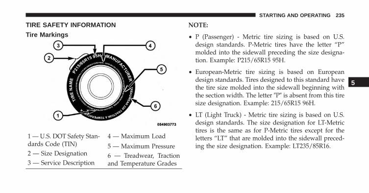
TIRE SAFETY INFORMATION
Tire Markings
NOTE:
• P (Passenger) - Metric tire sizing is based on U.S.design standards. P-Metric tires have the letter “P”molded into the sidewall preceding the size designa-tion. Example: P215/65R15 95H.
• European-Metric tire sizing is based on Europeandesign standards. Tires designed to this standard havethe tire size molded into the sidewall beginning withthe section width. The letter �P� is absent from this tiresize designation. Example: 215/65R15 96H.
• LT (Light Truck) - Metric tire sizing is based on U.S.design standards. The size designation for LT-Metrictires is the same as for P-Metric tires except for theletters “LT” that are molded into the sidewall preced-ing the size designation. Example: LT235/85R16.
1 — U.S. DOT Safety Stan-dards Code (TIN)
4 — Maximum Load
2 — Size Designation5 — Maximum Pressure
3 — Service Description6 — Treadwear, Tractionand Temperature Grades
5
STARTING AND OPERATING 235

• Temporary spare tires are designed for temporaryemergency use only. Temporary high pressure com-pact spare tires have the letter “T” or “S” molded intothe sidewall preceding the size designation. Example:T145/80D18 103M.
• High flotation tire sizing is based on U.S. designstandards and it begins with the tire diameter moldedinto the sidewall. Example: 31x10.5 R15 LT.
Tire Sizing ChartEXAMPLE:
Size Designation:P = Passenger car tire size based on U.S. design standards�....blank....� = Passenger car tire based on European design standardsLT = Light truck tire based on U.S. design standardsT or S = Temporary spare tire31 = Overall diameter in inches (in)215 = Section width in millimeters (mm)65 = Aspect ratio in percent (%)
— Ratio of section height to section width of tire10.5 = Section width in inches (in)
236 STARTING AND OPERATING
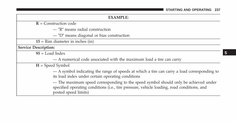
EXAMPLE:R = Construction code
— �R� means radial construction— �D� means diagonal or bias construction
15 = Rim diameter in inches (in)Service Description:
95 = Load Index— A numerical code associated with the maximum load a tire can carry
H = Speed Symbol— A symbol indicating the range of speeds at which a tire can carry a load corresponding toits load index under certain operating conditions— The maximum speed corresponding to the speed symbol should only be achieved underspecified operating conditions (i.e., tire pressure, vehicle loading, road conditions, andposted speed limits)
5
STARTING AND OPERATING 237

EXAMPLE:Load Identification:
�....blank....� = Absence of any text on the sidewall of the tire indicates a Standard Load (SL) tireExtra Load (XL) = Extra load (or reinforced) tireLight Load (LL) = Light load tireC, D, E, F, G = Load range associated with the maximum load a tire can carry at a specified pressure
Maximum Load— Maximum load indicates the maximum load this tire is designed to carryMaximum Pressure— Maximum pressure indicates the maximum permissible cold tire inflation pressure forthis tire
238 STARTING AND OPERATING
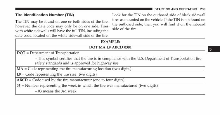
Tire Identification Number (TIN)
The TIN may be found on one or both sides of the tire,however, the date code may only be on one side. Tireswith white sidewalls will have the full TIN, including thedate code, located on the white sidewall side of the tire.
Look for the TIN on the outboard side of black sidewalltires as mounted on the vehicle. If the TIN is not found onthe outboard side, then you will find it on the inboardside of the tire.
EXAMPLE:DOT MA L9 ABCD 0301
DOT = Department of Transportation– This symbol certifies that the tire is in compliance with the U.S. Department of Transportation tiresafety standards and is approved for highway use
MA = Code representing the tire manufacturing location (two digits)L9 = Code representing the tire size (two digits)ABCD = Code used by the tire manufacturer (one to four digits)03 = Number representing the week in which the tire was manufactured (two digits)
– 03 means the 3rd week
5
STARTING AND OPERATING 239
EXAMPLE:DOT MA L9 ABCD 0301
01 = Number representing the year in which the tire was manufactured (two digits)– 01 means the year 2001– Prior to July 2000, tire manufacturers were only required to have one number to represent the yearin which the tire was manufactured. Example: 031 could represent the 3rd week of 1981 or 1991
Tire Terminology And Definitions
Term DefinitionB-Pillar The vehicle B-Pillar is the structural member of the body located
behind the front door.Cold Tire Inflation Pressure Cold tire inflation pressure is defined as the tire pressure after
the vehicle has not been driven for at least three hours, or drivenless than 1 mile (1.6 km) after sitting for a three hour period. In-flation pressure is measured in units of PSI (pounds per squareinch) or kPa (kilopascals).
240 STARTING AND OPERATING
Term DefinitionMaximum Inflation Pressure The maximum inflation pressure is the maximum permissible
cold tire inflation pressure for this tire. The maximum inflationpressure is molded into the sidewall.
Recommended Cold Tire InflationPressure
Vehicle manufacturer’s recommended cold tire inflation pressureas shown on the tire placard.
Tire Placard A paper label permanently attached to the vehicle describing thevehicle’s loading capacity, the original equipment tire sizes andthe recommended cold tire inflation pressures.
5
STARTING AND OPERATING 241

Tire Loading And Tire Pressure
Tire And Loading Information Placard Location
NOTE: The proper cold tire inflation pressure is listed onthe driver’s side B-Pillar or the rear edge of the driver’sside door.
Tire And Loading Information Placard
This placard tells you important information about the:
1. Number of people that can be carried in the vehicle.
2. Total weight your vehicle can carry.B-Pillar Location For Tire And Loading InformationPlacard
Tire And Loading Information Placard
242 STARTING AND OPERATING

3. Tire size designed for your vehicle.
4. Cold tire inflation pressures for the front, rear, andspare tires.
Loading
The vehicle maximum load on the tire must not exceedthe load carrying capacity of the tire on your vehicle. Youwill not exceed the tire’s load carrying capacity if youadhere to the loading conditions, tire size, and cold tireinflation pressures specified on the Tire and LoadingInformation placard and in the “Vehicle Loading” sectionof this manual.
NOTE: Under a maximum loaded vehicle condition,gross axle weight ratings (GAWRs) for the front and rearaxles must not be exceeded. For further information onGAWRs, vehicle loading, and trailer towing, refer to“Vehicle Loading” in this section.
To determine the maximum loading conditions of yourvehicle, locate the statement “The combined weight ofoccupants and cargo should never exceed XXX lbs orXXX kg” on the Tire and Loading Information placard.The combined weight of occupants, cargo/luggage andtrailer tongue weight (if applicable) should never exceedthe weight referenced here.
Steps For Determining Correct Load Limit
1. Locate the statement “The combined weight of occu-pants and cargo should never exceed XXX lbs orXXX kg” on your vehicle’s placard.
2. Determine the combined weight of the driver andpassengers that will be riding in your vehicle.
3. Subtract the combined weight of the driver and pas-sengers from XXX lbs or XXX kg.
4. The resulting figure equals the available amount ofcargo and luggage load capacity. For example, if
5
STARTING AND OPERATING 243

“XXX” amount equals 700 lbs (317 kg) and there willbe four 150 lb (68 kg) passengers in your vehicle, theamount of available cargo and luggage load capacityis 100 lbs (45 kg) (since 4 x 150 = 600, and 700 – 600 =100 lbs [45 kg]).
5. Determine the combined weight of luggage and cargobeing loaded on the vehicle. That weight may notsafely exceed the available cargo and luggage loadcapacity calculated in step 4.
6. If your vehicle will be towing a trailer, load from yourtrailer will be transferred to your vehicle. Consult thismanual to determine how this reduces the availablecargo and luggage load capacity of your vehicle.
NOTE:
• The following table shows examples on how to calcu-late total load, cargo/luggage, and towing capacitiesof your vehicle with varying seating configurationsand number and size of occupants. This table is forillustration purposes only and may not be accurate forthe seating and load carry capacity of your vehicle.
• For the following example, the combined weight ofoccupants and cargo should never exceed 700 lbs(317 kg).
244 STARTING AND OPERATING
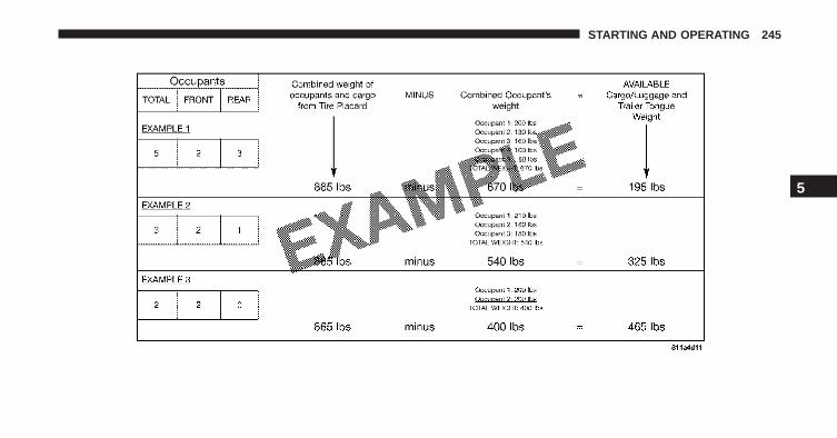
5
STARTING AND OPERATING 245
WARNING!
Overloading of your tires is dangerous. Overloadingcan cause tire failure, affect vehicle handling, andincrease your stopping distance. Use tires of therecommended load capacity for your vehicle. Neveroverload them.
TIRES — GENERAL INFORMATION
Tire Pressure
Proper tire inflation pressure is essential to the safe andsatisfactory operation of your vehicle. Three primaryareas are affected by improper tire pressure:
• Safety
• Economy
• Ride Comfort And Vehicle Stability
Safety
WARNING!
• Improperly inflated tires are dangerous and cancause collisions.
• Under-inflation increases tire flexing and can re-sult in over-heating and tire failure.
• Over-inflation reduces a tire’s ability to cushionshock. Objects on the road and chuckholes cancause damage that result in tire failure.
• Over-inflated or under-inflated tires can affect ve-hicle handling and can fail suddenly, resulting inloss of vehicle control.
• Unequal tire pressures can cause steering prob-lems. You could lose control of your vehicle.
(Continued)
246 STARTING AND OPERATING
WARNING! (Continued)• Unequal tire pressures from one side of the vehicle
to the other can cause the vehicle to drift to theright or left.
• Always drive with each tire inflated to the recom-mended cold tire inflation pressure.
Economy
Improper inflation pressures can cause uneven wear pat-terns to develop across the tire tread. These abnormal wearpatterns will reduce tread life resulting in a need for earliertire replacement. Under-inflation also increases tire rollingresistance resulting in higher fuel consumption.
Ride Comfort And Vehicle Stability
Proper tire inflation contributes to a comfortable ride.Over-inflation produces a jarring and uncomfortableride. Both under-inflation and over-inflation affect the
stability of the vehicle and can produce a feeling ofsluggish response or over responsiveness in the steering.
NOTE:
• Unequal tire pressures from side to side may causeerratic and unpredictable steering response.
• Unequal tire pressure from side to side may cause thevehicle to drift left or right.
Tire Inflation Pressures
The proper cold tire inflation pressure is listed on thedriver’s side B-Pillar or rear edge of the driver’s side door.
At least once a month:
• Check and adjust tire pressure with a good qualitypocket-type pressure gauge. Do not make a visualjudgement when determining proper inflation. Tiresmay look properly inflated even when they are under-inflated.
5
STARTING AND OPERATING 247
• Inspect tires for signs of tire wear or visible damage.
CAUTION!
After inspecting or adjusting the tire pressure, al-ways reinstall the valve stem cap. This will preventmoisture and dirt from entering the valve stem,which could damage the valve stem.
Inflation pressures specified on the placard are always“cold tire inflation pressure”. Cold tire inflation pressureis defined as the tire pressure after the vehicle has notbeen driven for at least three hours, or driven less than1 mile (1.6 km) after a three hour period. The cold tireinflation pressure must not exceed the maximum infla-tion pressure molded into the tire sidewall.
Check tire pressures more often if subject to a wide rangeof outdoor temperatures, as tire pressures vary withtemperature changes.
Tire pressures change by approximately 1 psi (7 kPa) per12°F (7°C) of air temperature change. Keep this in mindwhen checking tire pressure inside a garage, especially inthe winter.
Example: If garage temperature = 68°F (20°C) and theoutside temperature = 32°F (0°C) then the cold tireinflation pressure should be increased by 3 psi (21 kPa),which equals 1 psi (7 kPa) for every 12°F (7°C) for thisoutside temperature condition.
Tire pressure may increase from 2 to 6 psi (13 to 40 kPa)during operation. DO NOT reduce this normal pressurebuild up or your tire pressure will be too low.
248 STARTING AND OPERATING

Tire Pressures For High Speed Operation
The manufacturer advocates driving at safe speeds andwithin posted speed limits. Where speed limits or condi-tions are such that the vehicle can be driven at highspeeds, maintaining correct tire inflation pressure is veryimportant. Increased tire pressure and reduced vehicleloading may be required for high-speed vehicle opera-tion. Refer to your authorized tire dealer or originalequipment vehicle dealer for recommended safe operat-ing speeds, loading and cold tire inflation pressures.
WARNING!
High speed driving with your vehicle under maxi-mum load is dangerous. The added strain on yourtires could cause them to fail. You could have aserious collision. Do not drive a vehicle loaded to themaximum capacity at continuous speeds above75 mph (120 km/h).
Radial Ply Tires
WARNING!
Combining radial ply tires with other types of tireson your vehicle will cause your vehicle to handlepoorly. The instability could cause a collision. Al-ways use radial ply tires in sets of four. Nevercombine them with other types of tires.
Tire Repair
If your tire becomes damaged, it may be repaired if itmeets the following criteria:
• The tire has not been driven on when flat.
• The damage is only on the tread section of your tire(sidewall damage is not repairable).
• The puncture is no greater than ¼� (6 mm).
5
STARTING AND OPERATING 249
Consult an authorized tire dealer for tire repairs andadditional information.
Damaged Run Flat tires, or Run Flat tires that haveexperienced a loss of pressure should be replaced imme-diately with another Run Flat tire of identical size andservice description (Load Index and Speed Code).
Tire Types
All Season Tires — If Equipped
All Season tires provide traction for all seasons (spring,summer, fall and winter). Traction levels may vary be-tween different all season tires. All season tires can beidentified by the M+S, M&S, M/S or MS designation onthe tire sidewall. Use all season tires only in sets of four;failure to do so may adversely affect the safety andhandling of your vehicle.
Summer Or Three Season Tires — If Equipped
Summer tires provide traction in both wet and dryconditions, and are not intended to be driven in snow oron ice. If your vehicle is equipped with summer tires, beaware these tires are not designed for winter or colddriving conditions. For more information, contact a au-thorized dealer. Summer tires do not contain the allseason designation or mountain/snowflake symbol onthe tire sidewall.
Use summer tires only in sets of four; failure to do so mayadversely affect the safety and handling of your vehicle.
Snow Tires
Some areas of the country require the use of snow tiresduring the winter. Snow tires can be identified by amountain/snowflake symbol on the tire sidewall.
250 STARTING AND OPERATING

If you need snow tires, select tires equivalent in size andtype to the original equipment tires. Use snow tires onlyin sets of four; failure to do so may adversely affect thesafety and handling of your vehicle.
Snow tires generally have lower speed ratings than whatwas originally equipped with your vehicle and shouldnot be operated at sustained speeds over 75 mph(120 km/h). For speeds above 75 mph (120 km/h) refer tooriginal equipment or an authorized tire dealer forrecommended safe operating speeds, loading and coldtire inflation pressures.
While studded tires improve performance on ice, skidand traction capability on wet or dry surfaces may bepoorer than that of non-studded tires. Some states pro-hibit studded tires; therefore, local laws should bechecked before using these tire types.
Run Flat Tires — If Equipped
Run Flat tires allow you the capability to drive 50 miles(80 km) at 50 mph (80 km/h) after a rapid loss of inflationpressure. This rapid loss of inflation is referred to as theRun Flat mode. A Run Flat mode occurs when the tireinflation pressure is of/or below 14 psi (96 kPa). Once aRun Flat tire reaches the run flat mode it has limiteddriving capabilities and needs to be replaced immedi-ately. A Run Flat tire is not repairable.
It is not recommended driving a vehicle loaded at fullcapacity or to tow a trailer while a tire is in the run flatmode.
See the tire pressure monitoring section for more infor-mation.
5
STARTING AND OPERATING 251
Spare Tires — If Equipped
NOTE: For vehicles equipped with TIREFIT instead of aspare tire, please refer to “TIREFIT KIT” in “What To DoIn Emergencies” for further information.
CAUTION!
Because of the reduced ground clearance, do not takeyour vehicle through an automatic car wash with acompact, full size or limited-use temporary spareinstalled. Damage to the vehicle may result.
Spare Tire Matching Original Equipped Tire AndWheel — If Equipped
Your vehicle may be equipped with a spare tire andwheel equivalent in look and function to the originalequipment tire and wheel found on the front or rear axleof your vehicle. This spare tire may be used in the tire
rotation for your vehicle. If your vehicle has this option,refer to an authorized tire dealer for the recommendedtire rotation pattern.
Compact Spare Tire — If Equipped
The compact spare is for temporary emergency use only.You can identify if your vehicle is equipped with acompact spare by looking at the spare tire description onthe Tire and Loading Information Placard located on thedriver’s side door opening or on the sidewall of the tire.Compact spare tire descriptions begin with the letter “T”or “S” preceding the size designation. Example: T145/80D18 103M.
T, S = Temporary Spare Tire
Since this tire has limited tread life, the original equip-ment tire should be repaired (or replaced) and reinstalledon your vehicle at the first opportunity.
252 STARTING AND OPERATING
Do not install a wheel cover or attempt to mount aconventional tire on the compact spare wheel, since thewheel is designed specifically for the compact spare tire.Do not install more than one compact spare tire andwheel on the vehicle at any given time.
WARNING!
Compact spares are for temporary emergency useonly. With these spares, do not drive more than50 mph (80 km/h). Temporary use spares have limitedtread life. When the tread is worn to the tread wearindicators, the temporary use spare tire needs to bereplaced. Be sure to follow the warnings, whichapply to your spare. Failure to do so could result inspare tire failure and loss of vehicle control.
Full Size Spare — If Equipped
The full size spare is for temporary emergency use only.This tire may look like the originally equipped tire on the
front or rear axle of your vehicle, but it is not. This sparetire may have limited tread life. When the tread is wornto the tread wear indicators, the temporary use full sizespare tire needs to be replaced. Since it is not the same asyour original equipment tire, replace (or repair) theoriginal equipment tire and reinstall on the vehicle at thefirst opportunity.
Limited-Use Spare — If Equipped
The limited-use spare tire is for temporary emergencyuse only. This tire is identified by a label located on thelimited-use spare wheel. This label contains the drivinglimitations for this spare. This tire may look like theoriginal equipped tire on the front or rear axle of yourvehicle, but it is not. Installation of this limited-use sparetire affects vehicle handling. Since it is not the same asyour original equipment tire, replace (or repair) theoriginal equipment tire and reinstall on the vehicle at thefirst opportunity.
5
STARTING AND OPERATING 253

WARNING!
Limited-use spares are for emergency use only. In-stallation of this limited-use spare tire affects vehiclehandling. With this tire, do not drive more than thespeed listed on the limit-use spare wheel. Keepinflated to the cold tire inflation pressures listed onyour Tire and Loading Information Placard locatedon the driver’s side B-Pillar or the rear edge of thedriver’s side door. Replace (or repair) the originalequipment tire at the first opportunity and reinstall iton your vehicle. Failure to do so could result in lossof vehicle control.
Tire Spinning
When stuck in mud, sand, snow, or ice conditions, do notspin your vehicle’s wheels above 30 mph (48 km/h) orfor longer than 30 seconds continuously without stop-ping.
Refer to “Freeing A Stuck Vehicle” in “What To Do InEmergencies” for further information.
WARNING!
Fast spinning tires can be dangerous. Forces gener-ated by excessive wheel speeds may cause tire dam-age or failure. A tire could explode and injure some-one. Do not spin your vehicle’s wheels faster than30 mph (48 km/h) for more than 30 seconds continu-ously when you are stuck, and do not let anyone neara spinning wheel, no matter what the speed.
254 STARTING AND OPERATING

Tread Wear Indicators
Tread wear indicators are in the original equipment tiresto help you in determining when your tires should bereplaced.
These indicators are molded into the bottom of the treadgrooves. They will appear as bands when the tread depthbecomes 1/16 in (2 mm). When the tread is worn to thetread wear indicators, the tire should be replaced. Referto “Replacement Tires” in this section for further infor-mation.
Life Of Tire
The service life of a tire is dependent upon varyingfactors including, but not limited to:
• Driving style
• Tire pressure
• Distance driven
• Performance tires, tires with a speed rating of V orhigher, and summer tires typically have a reducedtread life. Rotation of these tires per the vehicle main-tenance schedule is highly recommended.
1 — Worn Tire2 — New Tire
5
STARTING AND OPERATING 255
WARNING!
Tires and the spare tire should be replaced after sixyears, regardless of the remaining tread. Failure tofollow this warning can result in sudden tire failure.You could lose control and have a collision resultingin serious injury or death.
Keep dismounted tires in a cool, dry place with as littleexposure to light as possible. Protect tires from contactwith oil, grease, and gasoline.
Replacement Tires
The tires on your new vehicle provide a balance of manycharacteristics. They should be inspected regularly forwear and correct cold tire inflation pressure. The manu-facturer strongly recommends that you use tires equiva-lent to the originals in size, quality and performancewhen replacement is needed. Refer to the paragraph on“Tread Wear Indicators”. Refer to the Tire and Loading
Information placard or the Vehicle Certification Label forthe size designation of your tire. The Load Index andSpeed Symbol for your tire will be found on the originalequipment tire sidewall. See the Tire Sizing Chart ex-ample found in the Tire Safety Information section of thismanual for more information relating to the Load Indexand Speed Symbol of a tire.
It is recommended to replace the two front tires or tworear tires as a pair. Replacing just one tire can seriouslyaffect your vehicle’s handling. If you ever replace awheel, make sure that the wheel’s specifications matchthose of the original wheels.
It is recommended you contact your authorized tiredealer or original equipment dealer with any questionsyou may have on tire specifications or capability. Failureto use equivalent replacement tires may adversely affectthe safety, handling, and ride of your vehicle.
256 STARTING AND OPERATING

WARNING!
• Do not use a tire, wheel size or rating other thanthat specified for your vehicle. Some combinationsof unapproved tires and wheels may change sus-pension dimensions and performance characteris-tics, resulting in changes to steering, handling, andbraking of your vehicle. This can cause unpredict-able handling and stress to steering and suspen-sion components. You could lose control and havea collision resulting in serious injury or death. Useonly the tire and wheel sizes with load ratingsapproved for your vehicle.
• Never use a tire with a smaller load index orcapacity, other than what was originally equippedon your vehicle. Using a tire with a smaller loadindex could result in tire overloading and failure.You could lose control and have a collision.
(Continued)
WARNING! (Continued)• Failure to equip your vehicle with tires having
adequate speed capability can result in sudden tirefailure and loss of vehicle control.
CAUTION!Replacing original tires with tires of a different sizemay result in false speedometer and odometer read-ings.
TIRE CHAINS (TRACTION DEVICES)
Use of traction devices require sufficient tire-to-bodyclearance. Follow these recommendations to guardagainst damage.
• Traction device must be of proper size for the tire, asrecommended by the traction device manufacturer
• Install on Front Tires
5
STARTING AND OPERATING 257

• Due to limited clearance, a 185/55R15 tire with aSecurity Chain Company (SCC) Super Z6 low profiletraction device or equivalent is recommended
WARNING!
Using tires of different size and type (M+S, Snow)between front and rear axles can cause unpredictablehandling. You could lose control and have a collision.
CAUTION!
To avoid damage to your vehicle or tires, observe thefollowing precautions:• Because of restricted chain clearance between tires
and other suspension components, it is importantthat only chains in good condition are used. Brokenchains can cause serious damage. Stop the vehicle
(Continued)
CAUTION! (Continued)immediately if noise occurs that could indicatechain breakage. Remove the damaged parts of thechain before further use.
• Install chains on the front wheels as tightly aspossible and then retighten after driving about ½mile (0.8 km).
• Do not exceed 30 mph (48 km/h).• Drive cautiously and avoid severe turns and large
bumps, especially with a loaded vehicle.• Do not drive for prolonged period on dry pavement.• Observe the tire chain manufacturer’s instructions on
the method of installation, operating speed, and con-ditions for use. Always use the lower suggested oper-ating speed of the chain manufacturer if differentfrom the speed recommended by the manufacture.
• Do not use traction devices on a compact spare tire.
258 STARTING AND OPERATING
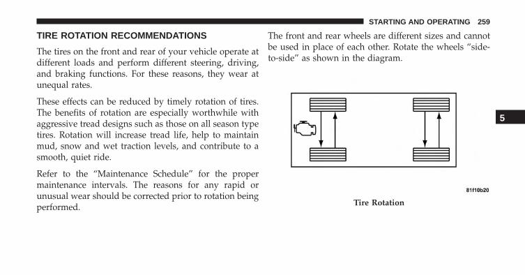
TIRE ROTATION RECOMMENDATIONS
The tires on the front and rear of your vehicle operate atdifferent loads and perform different steering, driving,and braking functions. For these reasons, they wear atunequal rates.
These effects can be reduced by timely rotation of tires.The benefits of rotation are especially worthwhile withaggressive tread designs such as those on all season typetires. Rotation will increase tread life, help to maintainmud, snow and wet traction levels, and contribute to asmooth, quiet ride.
Refer to the “Maintenance Schedule” for the propermaintenance intervals. The reasons for any rapid orunusual wear should be corrected prior to rotation beingperformed.
The front and rear wheels are different sizes and cannotbe used in place of each other. Rotate the wheels “side-to-side” as shown in the diagram.
Tire Rotation
5
STARTING AND OPERATING 259
PREMIUM TIRE PRESSURE MONITOR SYSTEM
The Tire Pressure Monitor System (TPMS) will warn thedriver of a low tire pressure based on the vehicle recom-mended cold placard pressure.
The tire pressure will vary with temperature by about1psi (6.9 kPa) for every 12°F (6.5°C). This means thatwhen the outside temperature decreases, the tire pressurewill decrease. Tire pressure should always be set basedon cold inflation tire pressure. This is defined as the tirepressure after the vehicle has not been driven for at leastthree hours, or driven less than 1 mile (1.6 km) after athree hour period. The cold tire inflation pressure mustnot exceed the maximum inflation pressure molded intothe tire sidewall. Refer to “Tires – General Information”in “Starting and Operating” for information on how toproperly inflate the vehicle’s tires. The tire pressure will
also increase as the vehicle is driven. This is normal andthere should be no adjustment for this increased pres-sure.
The TPMS will warn the driver of a low tire pressure ifthe tire pressure falls below the low-pressure warninglimit for any reason, including low temperature effectsand natural pressure loss through the tire.
The TPMS will continue to warn the driver of low tirepressure as long as the condition exists, and will not turnoff until the tire pressure is at or above the recommendedcold placard pressure. Once the low tire pressure warn-ing (Tire Pressure Monitoring Telltale Light) illuminates,you must increase the tire pressure to the recommendedcold placard pressure in order for the “Tire PressureMonitoring Telltale Light” to turn off. The system willautomatically update and the “Tire Pressure MonitoringTelltale Light” will turn off once the system receives theupdated tire pressures. The vehicle may need to be
260 STARTING AND OPERATING
driven for up to 20 minutes above 15 mph (24 km/h) inorder for the TPMS to receive this information.
For example, your vehicle may have a recommendedcold (parked for more than three hours) placard pressureof 33 psi (227 kPa). If the ambient temperature is 68°F(20°C) and the measured tire pressure is 28 psi (193 kPa),a temperature drop to 20°F (-7°C) will decrease the tirepressure to approximately 24 psi (165 kPa). This tirepressure is low enough to turn ON the “Tire PressureMonitoring Telltale Light.” Driving the vehicle may causethe tire pressure to rise to approximately 28 psi (193 kPa),but the “Tire Pressure Monitoring Telltale Light” will stillbe on. In this situation, the “Tire Pressure MonitoringTelltale Light” will turn off only after the tires are inflatedto the vehicle’s recommended cold placard pressurevalue.
CAUTION!
• The TPMS has been optimized for the originalequipment tires and wheels. TPMS pressures andwarnings have been established for the tire sizeequipped on your vehicle. Undesirable system op-eration or sensor damage may result when usingreplacement equipment that is not of the same size,type, and/or style. Aftermarket wheels can causesensor damage. Do not use aftermarket tire sealantsor balance beads if your vehicle is equipped with aTPMS, as damage to the sensors may result.
• After inspecting or adjusting the tire pressure,always reinstall the valve stem cap. This willprevent moisture and dirt from entering the valvestem, which could damage the Tire Pressure Moni-toring Sensor.
5
STARTING AND OPERATING 261

NOTE:
• The TPMS is not intended to replace normal tire careand maintenance, or to provide warning of a tirefailure or condition.
• The TPMS should not be used as a tire pressure gaugewhile adjusting your tire pressure.
• Driving on a significantly under-inflated tire causesthe tire to overheat and can lead to tire failure.
• Under-inflation also reduces fuel efficiency and tiretread life, and may affect the vehicle’s handling andstopping ability.
• It is particularly important for you to check the tirepressure in all of the tires on your vehicle monthly andto maintain the proper pressure.
• The TPMS is not a substitute for proper tire mainte-nance, and it is the driver’s responsibility to maintain
correct tire pressure using an accurate tire pressuregauge, even if under-inflation has not reached the levelto trigger illumination of the “Tire Pressure Monitor-ing Telltale Light.”
• Seasonal temperature changes will affect tire pressure,and the TPMS will monitor the actual tire pressure inthe tire.
Premium TPM System
The Tire Pressure Monitor System (TPMS) uses wirelesstechnology with wheel rim mounted electronic sensors tomonitor tire pressure levels. Sensors, mounted to eachwheel as part of the valve stem, transmit tire pressurereadings to the receiver module.
The TPMS consists of the following components:
• Receiver module
• Four Tire Pressure Monitoring Sensors
262 STARTING AND OPERATING

• Various Tire Pressure Monitoring System messages,which display in the Electronic Vehicle InformationCenter (EVIC)
• Tire Pressure Monitoring Telltale Light
Tire Pressure Monitoring Low Pressure Warnings
The “Tire Pressure Monitoring Telltale Light” willilluminate in the instrument cluster and a chime willsound when tire pressure is low in one or more of thefour active road tires. In addition, the ElectronicVehicle Information Center (EVIC) will display agraphic showing the pressure values of each tire withthe low tire pressure tire highlighted.
Should this occur, you should stop as soon as possibleand inflate the tires with low pressure to the vehicle’srecommended cold placard pressure value. Once thesystem receives the updated tire pressures, the systemwill automatically update and the “Tire Pressure Moni-toring Telltale Light” will turn off. The vehicle may need
Low Tire Indicator
5
STARTING AND OPERATING 263

to be driven for up to 20 minutes above 15 mph(24 km/h) in order for the TPMS to receive this informa-tion.
TPMS Warning
When a system fault is detected, the “Tire PressureMonitoring Telltale Light” will flash on and off for 75seconds and then remain on solid. The system fault willsound a chime and also display a “Service TPM System”message in the EVIC for approximately 3 seconds.
If the ignition switch is cycled, this sequence will repeat,providing the system fault still exists. If the system faultno longer exists, the “Tire Pressure Monitoring TelltaleLight” will no longer flash, and the “Service TPM Sys-tem” message will no longer display, and a pressurevalue will display in place of the dashes.
Service TPM System Message
264 STARTING AND OPERATING
NOTE:
• The TPMS will not monitor the pressure in a replace-ment tire installed without a tire pressure sensor.
• If you install a replacement tire in place of a road tirethat has a pressure below the low-pressure warninglimit, upon the next ignition switch cycle, the “TirePressure Monitoring Telltale Light” will remain on anda chime will sound. In addition, the graphic in theEVIC will still display a pressure value in a differentcolor.
• After driving the vehicle for up to 20 minutes above15 mph (24 km/h), the “Tire Pressure MonitoringTelltale Light” will flash on and off for 75 seconds andthen remain on solid. In addition, the EVIC willdisplay a “Service TPM System” message and thendisplay dashes (- -) in place of the pressure value.
• For each subsequent ignition switch cycle, a chime willsound, the “Tire Pressure Monitoring Telltale Light”will flash on and off for 75 seconds and then remain onsolid, and the EVIC will display a “Service TPMSystem” message and dashes (- -) in place of thepressure value.
Once you repair or replace the original road tire andreinstall it, the TPMS will update automatically. In addi-tion, the “Tire Pressure Monitoring Telltale Light” willturn off and the graphic in the EVIC will display a newpressure value instead of dashes (- -), as long as no tirepressure is below the low-pressure warning limit in anyof the four active road tires. The vehicle may need to bedriven for up to 20 minutes above 15 mph (24 km/h) inorder for the TPMS to receive this information.
5
STARTING AND OPERATING 265

General Information
This device complies with Part 15 of the FCC rules andRSS 210 of Industry Canada. Operation is subject to thefollowing conditions:
• This device may not cause harmful interference.
• This device must accept any interference received,including interference that may cause undesired op-eration. The tire pressure sensors are covered under
one of the following licenses: United StatesMRXC4W4MA4 Canada 2546A-C4W4MA4 1.
TRAILER TOWING
Trailer towing with this vehicle is not recommended.
RECREATIONAL TOWING (BEHIND MOTORHOME, ETC.)Towing This Vehicle Behind Another Vehicle
Towing Condition Wheels OFF the Ground Single-Speed TransmissionFlat Tow NONE NOT ALLOWED
Dolly Tow Front OKRear NOT ALLOWED
On Trailer ALL OK
266 STARTING AND OPERATING
NOTE: This vehicle must be towed on a dolly or vehicletrailer with the front wheels OFF the ground.
CAUTION!
Towing this vehicle in violation of the above require-ments can cause severe transmission damage. Dam-age from improper towing is not covered under theNew Vehicle Limited Warranty.
EXTENDING YOUR DRIVING RANGE PERCHARGE
The drive system and cabin temperature managementfeatures use the most energy from the high voltagebattery. Reducing energy draw from these features arethe easiest and most effective way to extend drivingrange.
The 500e uses high voltage components to heat and coolthe cabin, so when using automatic climate control,
consider setting temperatures a few degrees higher orlower during hot and cold days. If your 500e has beensoaking in hot or cold temperatures for an extendedperiod, it is recommended that the car be preconditionedusing the mobile application while still plugged into acharging source. This will allow 500e to use externalpower to establish a comfortable cabin temperature be-fore the drive and allow the battery to maintain thetemperature at significantly less energy levels.
Additional tips:
• keep tires properly inflated
• When practical, choose surface streets over the high-way, and work to maintain a steady speed
• avoid carrying nonessential cargo
• be mindful of adding external accessories that mayincrease aerodynamic drag
5
STARTING AND OPERATING 267

• perform all scheduled maintenance at recommendedintervals
Driver Behavior Gauge
To help the driver extend the driving range of the highvoltage battery your vehicle is equipped with a DriverBehavior Gauge. The Driver Behavior Gauge is locatedon the right side of the instrument cluster and containsthree driving ranges:
• Power
The needle will move into the Power range when underacceleration.
• ECO
The needle will move into the ECO range when you aremaximizing the driving range of the high voltage battery.
• Charge
The needle will move into the Charge range when batteryregeneration is active (either coasting or braking).
Driver Behavior Gauge
268 STARTING AND OPERATING

Range Projection
This area of the cluster is used to display the projectedrange of the high voltage battery. The two arrows to theleft of the mileage are used to forecast the effect of recentdriving.
• When both arrows are grey, expect the range to dropapproximately one mile for each mile driven.
• When the up arrow is highlighted, expect the rangenumber to hold steady or increase while driving.
• When the down arrow is highlighted, expect the rangenumber to decrease more than one mile for each miledriven.
Range Projection Indicators
5
STARTING AND OPERATING 269


WHAT TO DO IN EMERGENCIES
CONTENTS� HAZARD WARNING FLASHERS . . . . . . . . . . .272
� WHEEL AND TIRE TORQUESPECIFICATIONS . . . . . . . . . . . . . . . . . . . . . .272
▫ Torque Specifications . . . . . . . . . . . . . . . . . . .272
� TIREFIT KIT — IF EQUIPPED . . . . . . . . . . . . .274
▫ TIREFIT Storage . . . . . . . . . . . . . . . . . . . . . .274
▫ TIREFIT Kit Components And Operation . . . . .275
▫ TIREFIT Usage Precautions. . . . . . . . . . . . . . .276
▫ Sealing A Tire With TIREFIT . . . . . . . . . . . . . .278
� JUMP-STARTING PROCEDURE(12 VOLT BATTERY ONLY). . . . . . . . . . . . . . . .284
▫ Preparations For Jump-Start . . . . . . . . . . . . . .285
▫ Jump-Starting Procedure . . . . . . . . . . . . . . . .286
� FREEING A STUCK VEHICLE . . . . . . . . . . . . .287
� MANUAL PARK RELEASE . . . . . . . . . . . . . . . .288
� TOWING A DISABLED VEHICLE . . . . . . . . . . .291
6
HAZARD WARNING FLASHERS
The Hazard Warning flasher switch is located on theinstrument panel below the radio.
Press the switch to turn on the Hazard Warningflashers. When the switch is activated, all direc-
tional turn signals will flash on and off to warn oncomingtraffic of an emergency. Press the switch a second time toturn off the Hazard Warning flashers.
Do not use this emergency warning system when thevehicle is in motion. Use it when your vehicle is disabledand it is creating a safety hazard for other motorists.
If it is necessary to leave the vehicle to go for service, theHazard Warning flashers will continue to operate withthe ignition key removed and the vehicle locked.
NOTE: With extended use, the Hazard Warning flashersmay wear down your battery.
WHEEL AND TIRE TORQUE SPECIFICATIONS
Proper lug nut/bolt torque is very important to ensurethat the wheel is properly mounted to the vehicle. Anytime a wheel has been removed and reinstalled on thevehicle the lug nuts/bolts should be torqued using aproperly calibrated torque wrench.
Torque Specifications
Lug Nut/Bolt Torque **Lug Nut/Bolt Size
Lug Nut/Bolt Socket
Size66 Ft-Lbs (90 N·m)Steel Wheels Only75 Ft-Lbs (100 N·m)Aluminum Wheels
Only
M12 x 1.25 17 mm
**Use only your authorized dealer recommended lugnuts/bolts and clean or remove any dirt or oil beforetightening.
272 WHAT TO DO IN EMERGENCIES

Inspect the wheel mounting surface prior to mountingthe tire and remove any corrosion or loose particles.
Tighten the lug nuts/bolts in a star pattern until eachnut/bolt has been tightened twice.
After 25 miles (40 km) check the lug nut/bolt torque to besure that all the lug nuts/bolts are properly seatedagainst the wheel.
Wheel Mounting Surface
Torque Patterns
6
WHAT TO DO IN EMERGENCIES 273

WARNING!
To avoid the risk of forcing the vehicle off the jack,do not tighten the lug nuts fully until the vehicle hasbeen lowered. Failure to follow this warning mayresult in personal injury.
TIREFIT KIT — IF EQUIPPED
Small punctures up to ¼” (6 mm) in the tire tread can besealed with TIREFIT. Foreign objects (e.g., screws ornails) should not be removed from the tire. TIREFIT canbe used in outside temperatures down to approximately-4°F (-20°C).
This kit will provide a temporary tire seal, allowing youto drive your vehicle up to 100 miles (160 km) with amaximum speed of 55 mph (90 km/h).
TIREFIT Storage
The TIREFIT kit is located in the rear cargo area.
TIREFIT Location
274 WHAT TO DO IN EMERGENCIES

TIREFIT Kit Components And Operation Using The Mode Select Knob And Hoses
Your TIREFIT kit is equipped with the following symbolsto indicate the air or sealant mode.
Selecting Air Mode
Push in the Mode Select Knob (5) and turn to thisposition for air pump operation only. Use the
Black Air Pump Hose (7) when selecting this mode.
Selecting Sealant Mode
Push in the Mode Select Knob (5) and turn to thisposition to inject the TIREFIT Sealant and to
inflate the tire. Use the Sealant Hose (clear hose) (6) whenselecting this mode.
Using The Power Button
Push and release the Power Button (4) once toturn On the TIREFIT kit. Push and release the PowerButton (4) again to turn Off the TIREFIT kit.
TIREFIT Components
1 — Sealant Bottle 5 — Mode Select Knob2 — Deflation Button 6 — Sealant Hose (Clear)3 — Pressure Gauge 7 — Air Pump Hose (Black)4 — Power Button 8 — Power Plug (located on bottom
side of TIREFIT Kit)
6
WHAT TO DO IN EMERGENCIES 275
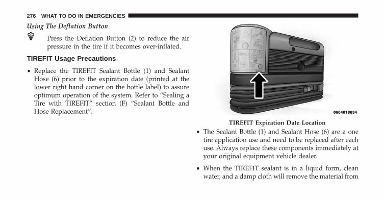
Using The Deflation Button
Press the Deflation Button (2) to reduce the airpressure in the tire if it becomes over-inflated.
TIREFIT Usage Precautions
• Replace the TIREFIT Sealant Bottle (1) and SealantHose (6) prior to the expiration date (printed at thelower right hand corner on the bottle label) to assureoptimum operation of the system. Refer to “Sealing aTire with TIREFIT” section (F) “Sealant Bottle andHose Replacement”.
• The Sealant Bottle (1) and Sealant Hose (6) are a onetire application use and need to be replaced after eachuse. Always replace these components immediately atyour original equipment vehicle dealer.
• When the TIREFIT sealant is in a liquid form, cleanwater, and a damp cloth will remove the material from
TIREFIT Expiration Date Location
276 WHAT TO DO IN EMERGENCIES
the vehicle or tire and wheel components. Once thesealant dries, it can easily be peeled off and properlydiscarded.
• For optimum performance, make sure the valve stemon the wheel is free of debris before connecting theTIREFIT kit.
• You can use the TIREFIT air pump to inflate bicycletires. The kit also comes with two needles, located inthe Accessory Storage Compartment (on the bottom ofthe air pump) for inflating sport balls, rafts, or similarinflatable items. However, use only the Air Pump Hose(7) and make sure the Mode Select Knob (5) is in theAir Mode when inflating such items to avoid injectingsealant into them. The TIREFIT Sealant is only in-tended to seal punctures less than ¼” (6 mm) diameterin the tread of your vehicle.
• Do not lift or carry the TIREFIT kit by the hoses.
WARNING!
• Do not attempt to seal a tire on the side of thevehicle closest to traffic. Pull far enough off theroad to avoid the danger of being hit when usingthe TIREFIT kit.
• Do not use TIREFIT or drive the vehicle under thefollowing circumstances:– If the puncture in the tire tread is approximately
1/4” (6 mm) or larger.– If the tire has any sidewall damage.– If the tire has any damage from driving with
extremely low tire pressure.– If the tire has any damage from driving on a flat
tire.– If the wheel has any damage.– If you are unsure of the condition of the tire or
the wheel.
(Continued)
6
WHAT TO DO IN EMERGENCIES 277
WARNING! (Continued)• Keep TIREFIT away from open flames or heat
source.• A loose TIREFIT kit thrown forward in a collision
or hard stop could endanger the occupants of thevehicle. Always stow the TIREFIT kit in the placeprovided. Failure to follow these warnings canresult in injuries that are serious or fatal to you,your passengers, and others around you.
• Take care not to allow the contents of TIREFIT tocome in contact with hair, eyes, or clothing. TIRE-FIT is harmful if inhaled, swallowed, or absorbedthrough the skin. It causes skin, eye, and respira-tory irritation. Flush immediately with plenty ofwater if there is any contact with eyes or skin.Change clothing as soon as possible, if there is anycontact with clothing.
(Continued)
WARNING! (Continued)• TIREFIT Sealant solution contains latex. In case of
an allergic reaction or rash, consult a physicianimmediately. Keep TIREFIT out of reach of children.If swallowed, rinse mouth immediately with plentyof water and drink plenty of water. Do not inducevomiting! Consult a physician immediately.
Sealing A Tire With TIREFIT
(A) Whenever You Stop To Use TIREFIT:
1. Pull over to a safe location and turn on the vehicle’sHazard Warning flashers.
2. Verify that the valve stem (on the wheel with thedeflated tire) is in a position that is near to the ground.This will allow the TIREFIT Hoses (6) and (7) to reachthe valve stem and keep the TIREFIT kit flat on theground. This will provide the best positioning of the kit
278 WHAT TO DO IN EMERGENCIES
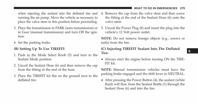
when injecting the sealant into the deflated tire andrunning the air pump. Move the vehicle as necessary toplace the valve stem in this position before proceeding.
3. Place the transmission in PARK (auto transmission) orin Gear (manual transmission) and turn Off the igni-tion.
4. Set the parking brake.
(B) Setting Up To Use TIREFIT:
1. Push in the Mode Select Knob (5) and turn to theSealant Mode position.
2. Uncoil the Sealant Hose (6) and then remove the capfrom the fitting at the end of the hose.
3. Place the TIREFIT kit flat on the ground next to thedeflated tire.
4. Remove the cap from the valve stem and then screwthe fitting at the end of the Sealant Hose (6) onto thevalve stem.
5. Uncoil the Power Plug (8) and insert the plug into thevehicle’s 12 Volt power outlet.
NOTE: Do not remove foreign objects (e.g., screws ornails) from the tire.
(C) Injecting TIREFIT Sealant Into The DeflatedTire:
• Always start the engine before turning ON the TIRE-FIT kit.
NOTE: Manual transmission vehicles must have theparking brake engaged and the shift lever in NEUTRAL.
• After pressing the Power Button (4), the sealant (whitefluid) will flow from the Sealant Bottle (1) through theSealant Hose (6) and into the tire.
6
WHAT TO DO IN EMERGENCIES 279

NOTE: Sealant may leak out through the puncture in thetire.
If the sealant (white fluid) does not flow within 0 – 10seconds through the Sealant Hose (6):
1. Press the Power Button (4) to turn Off the TIREFIT kit.Disconnect the Sealant Hose (6) from the valve stem.Make sure the valve stem is free of debris. Reconnectthe Sealant Hose (6) to the valve stem. Check that theMode Select Knob (5) is in the Sealant Mode positionand not Air Mode. Press the Power Button (4) to turnOn the TIREFIT kit.
2. Connect the Power Plug (8) to a different 12 Voltpower outlet in your vehicle or another vehicle, ifavailable. Make sure the engine is running beforeturning ON the TIREFIT kit.
3. The Sealant Bottle (1) may be empty due to previoususe. Call for assistance.
NOTE: If the Mode Select Knob (5) is on Air Mode andthe pump is operating, air will dispense from the AirPump Hose (7) only, not the Sealant Hose (6).
If the sealant (white fluid) does flow through theSealant Hose (6):
1. Continue to operate the pump until sealant is nolonger flowing through hose (typically takes 30 - 70seconds). As the sealant flows through the SealantHose (6), the Pressure Gauge (3) can read as high as 70psi (4.8 Bar). The Pressure Gauge (3) will decreasequickly from approximately 70 psi (4.8 Bar) to theactual tire pressure when the Sealant Bottle (1) isempty.
2. The pump will start to inject air into the tire immedi-ately after the Sealant Bottle (1) is empty. Continue tooperate the pump and inflate the tire to the pressureindicated on the tire pressure label on the driver-side
280 WHAT TO DO IN EMERGENCIES
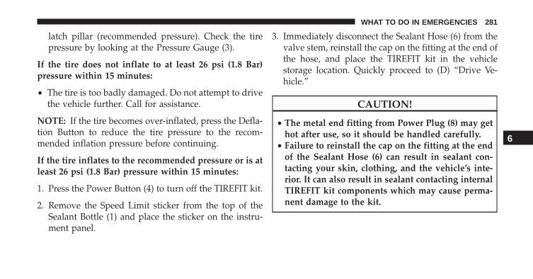
latch pillar (recommended pressure). Check the tirepressure by looking at the Pressure Gauge (3).
If the tire does not inflate to at least 26 psi (1.8 Bar)pressure within 15 minutes:
• The tire is too badly damaged. Do not attempt to drivethe vehicle further. Call for assistance.
NOTE: If the tire becomes over-inflated, press the Defla-tion Button to reduce the tire pressure to the recom-mended inflation pressure before continuing.
If the tire inflates to the recommended pressure or is atleast 26 psi (1.8 Bar) pressure within 15 minutes:
1. Press the Power Button (4) to turn off the TIREFIT kit.
2. Remove the Speed Limit sticker from the top of theSealant Bottle (1) and place the sticker on the instru-ment panel.
3. Immediately disconnect the Sealant Hose (6) from thevalve stem, reinstall the cap on the fitting at the end ofthe hose, and place the TIREFIT kit in the vehiclestorage location. Quickly proceed to (D) “Drive Ve-hicle.”
CAUTION!
• The metal end fitting from Power Plug (8) may gethot after use, so it should be handled carefully.
• Failure to reinstall the cap on the fitting at the endof the Sealant Hose (6) can result in sealant con-tacting your skin, clothing, and the vehicle’s inte-rior. It can also result in sealant contacting internalTIREFIT kit components which may cause perma-nent damage to the kit.
6
WHAT TO DO IN EMERGENCIES 281
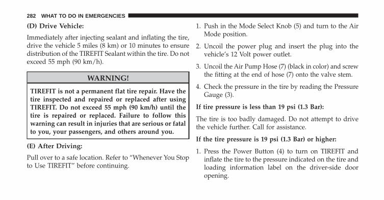
(D) Drive Vehicle:
Immediately after injecting sealant and inflating the tire,drive the vehicle 5 miles (8 km) or 10 minutes to ensuredistribution of the TIREFIT Sealant within the tire. Do notexceed 55 mph (90 km/h).
WARNING!
TIREFIT is not a permanent flat tire repair. Have thetire inspected and repaired or replaced after usingTIREFIT. Do not exceed 55 mph (90 km/h) until thetire is repaired or replaced. Failure to follow thiswarning can result in injuries that are serious or fatalto you, your passengers, and others around you.
(E) After Driving:
Pull over to a safe location. Refer to “Whenever You Stopto Use TIREFIT” before continuing.
1. Push in the Mode Select Knob (5) and turn to the AirMode position.
2. Uncoil the power plug and insert the plug into thevehicle’s 12 Volt power outlet.
3. Uncoil the Air Pump Hose (7) (black in color) and screwthe fitting at the end of hose (7) onto the valve stem.
4. Check the pressure in the tire by reading the PressureGauge (3).
If tire pressure is less than 19 psi (1.3 Bar):
The tire is too badly damaged. Do not attempt to drivethe vehicle further. Call for assistance.
If the tire pressure is 19 psi (1.3 Bar) or higher:
1. Press the Power Button (4) to turn on TIREFIT andinflate the tire to the pressure indicated on the tire andloading information label on the driver-side dooropening.
282 WHAT TO DO IN EMERGENCIES
NOTE: If the tire becomes over-inflated, press the Defla-tion Button to reduce the tire pressure to the recom-mended inflation pressure before continuing.
2. Disconnect the TIREFIT kit from the valve stem,reinstall the cap on the valve stem and unplug from 12Volt outlet.
3. Place the TIREFIT kit in its proper storage area in thevehicle.
4. Have the tire inspected and repaired or replaced at theearliest opportunity at an authorized dealer or tireservice center.
5. Replace the Sealant Bottle (1) and Sealant Hose (6)assembly at your authorized dealer as soon as pos-sible. Refer to (F) “Sealant Bottle and Hose Replace-ment”.
NOTE: When having the tire serviced, advise the autho-rized dealer or service center that the tire has been sealedusing the TIREFIT service kit.
(F) Sealant Bottle And Hose Replacement:
1. Uncoil the Sealant Hose (6) (clear in color).
2. Locate the round Sealant Bottle release button in therecessed area under the sealant bottle.
3. Press the Sealant Bottle release button. The SealantBottle (1) will pop up. Remove the bottle and disposeof it accordingly.
4. Clean any remaining sealant from the TIREFIT hous-ing.
5. Position the new Sealant Bottle (1) in the housing sothat the Sealant Hose (6) aligns with the hose slot in
6
WHAT TO DO IN EMERGENCIES 283
the front of the housing. Press the bottle into thehousing. An audible click will be heard indicating thebottle is locked into place.
6. Verify that the cap is installed on the fitting at the endof the Sealant Hose (6) and return the hose to itsstorage area (located on the bottom of the air pump).
7. Return the TIREFIT kit to its storage location in thevehicle.
JUMP-STARTING PROCEDURE (12 VOLTBATTERY ONLY)
If your vehicle has a discharged 12 Volt battery, it can bejump-started using a set of jumper cables and a battery inanother vehicle or by using a portable battery boosterpack. Jump-starting can be dangerous if done improperlyso please follow the procedures in this section carefully.
NOTE: When using a portable battery booster pack,follow the manufacturer’s operating instructions andprecautions.
WARNING!
Do not attempt jump-starting if the battery is frozen.It could rupture or explode and cause personal injury.
CAUTION!
Do not use a portable battery booster pack or anyother booster source with a system voltage greaterthan 12 Volts or damage to the battery, power elec-tronics or electrical system may occur.
284 WHAT TO DO IN EMERGENCIES
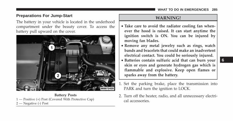
Preparations For Jump-Start
The battery in your vehicle is located in the underhoodcompartment under the beauty cover. To access thebattery pull upward on the cover.
WARNING!
• Take care to avoid the radiator cooling fan when-ever the hood is raised. It can start anytime theignition switch is ON. You can be injured bymoving fan blades.
• Remove any metal jewelry such as rings, watchbands and bracelets that could make an inadvertentelectrical contact. You could be seriously injured.
• Batteries contain sulfuric acid that can burn yourskin or eyes and generate hydrogen gas which isflammable and explosive. Keep open flames orsparks away from the battery.
1. Set the parking brake, place the transmission intoPARK and turn the ignition to LOCK.
2. Turn off the heater, radio, and all unnecessary electri-cal accessories.
Battery Posts1 — Positive (+) Post (Covered With Protective Cap)2 — Negative (-) Post
6
WHAT TO DO IN EMERGENCIES 285
3. Remove the protective cover over the positive (+)battery post.
4. If using another vehicle to jump-start the battery, parkthe vehicle within the jumper cables reach, set theparking brake and make sure the ignition is OFF.
WARNING!
Do not allow vehicles to touch each other as thiscould establish a ground connection and personalinjury could result.
Jump-Starting Procedure
WARNING!
Failure to follow this jump-starting procedure couldresult in personal injury or property damage due tobattery explosion.
CAUTION!
Failure to follow these procedures could result indamage to the charging system of the booster vehicleor the discharged vehicle.
Connecting The Jumper Cables
1. Connect the positive (+) end of the jumper cable to thepositive (+) post of the discharged vehicle.
2. Connect the opposite end of the positive (+) jumpercable to the positive (+) post of the booster battery.
3. Connect the negative end (-) of the jumper cable to thenegative (-) post of the booster battery.
4. Connect the opposite end of the negative (-) jumpercable to a good engine ground (exposed metal part ofthe discharged vehicle underhood compartment)away from the battery.
286 WHAT TO DO IN EMERGENCIES

WARNING!
Do not connect the jumper cable to the negative (-) postof the discharged battery. The resulting electrical sparkcould cause the battery to explode and could result inpersonal injury. Only use the specific ground point, donot use any other exposed metal parts.
5. Start the engine in the vehicle that has the boosterbattery, let the engine idle a few minutes, and thenturn the key to RUN position on the vehicle with thedischarged battery.
6. Once the vehicle is started, remove the jumper cablesin the reverse sequence:
Disconnecting The Jumper Cables
1. Disconnect the negative (-) jumper cable from theengine ground (-) of the vehicle with the dischargedbattery.
2. Disconnect the negative end (-) of the jumper cablefrom the negative (-) post of the booster battery.
3. Disconnect the opposite end of the positive (+) jumpercable from the positive (+) post of the booster battery.
4. Disconnect the positive (+) end of the jumper cablefrom the positive (+) post of the discharged vehicle.
If frequent jump-starting is required to start your vehicle,you should have the battery and charging system in-spected at your authorized dealer.
FREEING A STUCK VEHICLE
If your vehicle becomes stuck in mud, sand or snow, it canoften be moved using a rocking motion. Turn the steeringwheel right and left to clear the area around the frontwheels. Then shift back and forth between DRIVE andREVERSE while gently pressing the accelerator. Use theleast amount of accelerator pedal pressure that will main-tain the rocking motion, without spinning the wheels.
6
WHAT TO DO IN EMERGENCIES 287

NOTE: Press the �ESC Off� switch, to place the ElectronicStability Control (ESC) system in �Partial Off� mode,before rocking the vehicle. Refer to “Electronic BrakeControl” in “Starting And Operating” for further infor-mation. Once the vehicle has been freed, press the �ESCOff� switch again to restore �ESC On� mode.
CAUTION!
• When “rocking” a stuck vehicle by shifting be-tween DRIVE and REVERSE, do not spin thewheels faster than 15 mph (24 km/h), or drivetraindamage may result.
• Spinning the wheels too fast may lead to transmis-sion overheating and failure. It can also damage thetires. Do not spin the wheels above 30 mph(48 km/h) while in gear.
WARNING!
Fast spinning tires can be dangerous. Forces gener-ated by excessive wheel speeds may cause damage, oreven failure, of the axle and tires. A tire couldexplode and injure someone. Do not spin your vehi-cle’s wheels faster than 30 mph (48 km/h) or forlonger than 30 seconds continuously without stop-ping when you are stuck and do not let anyone neara spinning wheel, no matter what the speed.
MANUAL PARK RELEASE
WARNING!
Always secure your vehicle by fully applying theparking brake, before activating the Manual ParkRelease. Activating the Manual Park Release will
(Continued)
288 WHAT TO DO IN EMERGENCIES
WARNING! (Continued)allow your vehicle to roll away if it is not secured bythe parking brake or other means. Activating theManual Park Release on an unsecured vehicle couldlead to serious injury or death for those in or aroundthe vehicle.
In order to move the vehicle in cases where the transmis-sion will not shift out of PARK (such as a dead battery),a Manual Park Release is available. If a dead 12 voltbattery is the cause of the condition refer to “Jump StartProcedure — 12 Volt Battery” before performing theManual Park Release.
To perform the Manual Park Release follow these steps:
• To prevent the vehicle from rolling unintentionally,firmly apply the parking brake.
• If possible, raise the front driver’s side of the vehicle toprovide access to the transmission.
• Working from underneath the vehicle, remove theblack rubber plug from the front of the Park module (ablack canister mounted on the front of the transmis-sion).
• Using a T25 driver bit, rotate the Manual Park Releaseshaft (located just behind the rubber plug) clockwise,at least 20 turns, to release the Park mechanism. Thevehicle is now out of PARK and can be moved.
6
WHAT TO DO IN EMERGENCIES 289
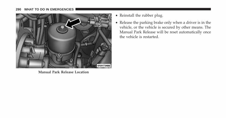
• Reinstall the rubber plug.
• Release the parking brake only when a driver is in thevehicle, or the vehicle is secured by other means. TheManual Park Release will be reset automatically oncethe vehicle is restarted.
Manual Park Release Location
290 WHAT TO DO IN EMERGENCIES

TOWING A DISABLED VEHICLEThis section describes procedures for towing a disabledvehicle using a commercial wrecker service.
Towing Condition Wheels OFF The Ground SINGLE-SPEED TRANSMISSIONFlat Tow NONE NOT ALLOWED
Wheel Lift Rear NOT ALLOWEDFront OK
Flatbed ALL OK
This vehicle must be towed with the front wheels OFF theground.
If you must use the accessories (wipers, defrosters, etc.)while being towed, the ignition must be in the ON/RUNposition, not the ACC position.
If the ignition key is unavailable, or the battery isdischarged, see “Manual Park Release” in “What To DoIn Emergencies” for instructions on shifting the transmis-sion out of PARK for loading the vehicle onto a flatbedtruck.
6
WHAT TO DO IN EMERGENCIES 291

CAUTION!
• DO NOT use sling-type equipment when towing.Vehicle damage may occur.
• When securing the vehicle to a flatbed truck, do notattach to front or rear suspension components.Damage to your vehicle may result from impropertowing.
292 WHAT TO DO IN EMERGENCIES
MAINTAINING YOUR VEHICLE
CONTENTS� UNDERHOOD COMPARTMENT . . . . . . . . . . .295
� REPLACEMENT PARTS . . . . . . . . . . . . . . . . . .296
� DEALER SERVICE . . . . . . . . . . . . . . . . . . . . . .296
� MAINTENANCE PROCEDURES . . . . . . . . . . .297▫ Power Electronics And Battery Thermal
Management Systems. . . . . . . . . . . . . . . . . . .298
▫ Power Electronics and Battery ThermalManagement Systems — Coolant LevelCheck. . . . . . . . . . . . . . . . . . . . . . . . . . . . . .298
▫ Power Electronics and Battery ThermalManagement Systems — Cooling PressureCaps. . . . . . . . . . . . . . . . . . . . . . . . . . . . . . .300
▫ Selection Of Coolant . . . . . . . . . . . . . . . . . . .301
▫ Adding Coolant. . . . . . . . . . . . . . . . . . . . . . .302
▫ Power Electronics and Battery ThermalManagement Systems — Drain, Flush AndRefill . . . . . . . . . . . . . . . . . . . . . . . . . . . . . .303
▫ Disposal Of Used Power Electronics andBattery Thermal Management SystemsCoolant. . . . . . . . . . . . . . . . . . . . . . . . . . . . .303
▫ Points To Remember . . . . . . . . . . . . . . . . . . .304
▫ Maintenance-Free Battery 12 Volt . . . . . . . . . .304
▫ Air Conditioner Maintenance . . . . . . . . . . . . .305
7

▫ Body Lubrication . . . . . . . . . . . . . . . . . . . . .306
▫ Wiper Blades . . . . . . . . . . . . . . . . . . . . . . . .307
▫ Adding Washer Fluid . . . . . . . . . . . . . . . . . .309
▫ Brake System . . . . . . . . . . . . . . . . . . . . . . . .310
▫ Appearance Care And Protection FromCorrosion . . . . . . . . . . . . . . . . . . . . . . . . . . .312
� FUSES . . . . . . . . . . . . . . . . . . . . . . . . . . . . . .319
▫ Interior Fuses . . . . . . . . . . . . . . . . . . . . . . . .320
▫ Power Distribution Center #1 . . . . . . . . . . . . .323
▫ Power Distribution Center (PDC) #2 . . . . . . . .326
� VEHICLE STORAGE. . . . . . . . . . . . . . . . . . . . .328
� REPLACEMENT BULBS . . . . . . . . . . . . . . . . .328
� BULB REPLACEMENT . . . . . . . . . . . . . . . . . .329
▫ Headlamps Low Beam and High Beam . . . . . .329
▫ Front Turn Signal, Parking And DaytimeRunning Lamps. . . . . . . . . . . . . . . . . . . . . . .330
▫ Front Fog Lamps . . . . . . . . . . . . . . . . . . . . . .331
▫ Front/Rear Side Marker Lamps. . . . . . . . . . . .331
▫ Rear Tail, Stop, Backup And Turn SignalLamps . . . . . . . . . . . . . . . . . . . . . . . . . . . . .331
▫ Center High Mounted Stop Lamp (CHMSL). . .332
� FLUID CAPACITIES . . . . . . . . . . . . . . . . . . . . .332
� FLUIDS, LUBES, AND GENUINE PARTS . . . . . .333
294 MAINTAINING YOUR VEHICLE
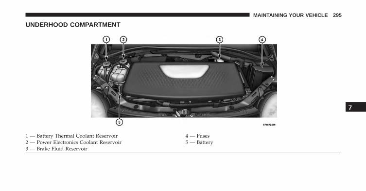
UNDERHOOD COMPARTMENT
1 — Battery Thermal Coolant Reservoir 4 — Fuses2 — Power Electronics Coolant Reservoir 5 — Battery3 — Brake Fluid Reservoir
7
MAINTAINING YOUR VEHICLE 295

REPLACEMENT PARTS
Use of genuine parts for normal/scheduled maintenanceand repairs is highly recommended to ensure the de-signed performance. Damage or failures caused by theuse of parts which are not quality-equivalent to genuineparts for maintenance and repairs will not be covered bythe manufacturer’s warranty.
DEALER SERVICE
Your authorized dealer has the qualified service person-nel, special tools, and equipment to perform all serviceoperations in an expert manner. Service Manuals areavailable which include detailed service information foryour vehicle. Refer to these Service Manuals beforeattempting any procedure yourself.
NOTE: Intentional tampering with emissions controlsystems may void your warranty and could result in civilpenalties being assessed against you.
WARNING!
You can be badly injured working on or around amotor vehicle. Only do service work for which youhave the knowledge and the proper equipment. Ifyou have any doubt about your ability to perform aservice job, take your vehicle to a competent me-chanic.
296 MAINTAINING YOUR VEHICLE
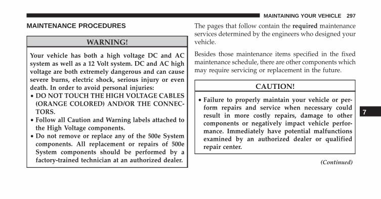
MAINTENANCE PROCEDURES
WARNING!
Your vehicle has both a high voltage DC and ACsystem as well as a 12 Volt system. DC and AC highvoltage are both extremely dangerous and can causesevere burns, electric shock, serious injury or evendeath. In order to avoid personal injuries:• DO NOT TOUCH THE HIGH VOLTAGE CABLES
(ORANGE COLORED) AND/OR THE CONNEC-TORS.
• Follow all Caution and Warning labels attached tothe High Voltage components.
• Do not remove or replace any of the 500e Systemcomponents. All replacement or repairs of 500eSystem components should be performed by afactory-trained technician at an authorized dealer.
The pages that follow contain the required maintenanceservices determined by the engineers who designed yourvehicle.
Besides those maintenance items specified in the fixedmaintenance schedule, there are other components whichmay require servicing or replacement in the future.
CAUTION!
• Failure to properly maintain your vehicle or per-form repairs and service when necessary couldresult in more costly repairs, damage to othercomponents or negatively impact vehicle perfor-mance. Immediately have potential malfunctionsexamined by an authorized dealer or qualifiedrepair center.
(Continued)
7
MAINTAINING YOUR VEHICLE 297

CAUTION! (Continued)• Your vehicle has been built with improved fluids
that protect the performance and durability of yourvehicle and also allow extended maintenance inter-vals. Do not use chemical flushes in these compo-nents as the chemicals can damage them. Suchdamage is not covered by the New Vehicle LimitedWarranty. If a flush is needed because of compo-nent malfunction, use only the specified fluid forthe flushing procedure.
Power Electronics And Battery ThermalManagement Systems
The Power Electronics and Battery Thermal ManagementSystems are completely separate and designed to regu-late temperature for the high voltage battery and theelectric components.
Power Electronics and Battery ThermalManagement Systems — Coolant Level Check
The coolant expansion bottles provides a quick visualmethod for determining that the coolant level is ad-equate. With the vehicle off and coolant at ambienttemperature, the level of the coolant (antifreeze) in thebottles should be between the bottom and top linesmarked “MIN-MAX FILL RANGE”.
298 MAINTAINING YOUR VEHICLE
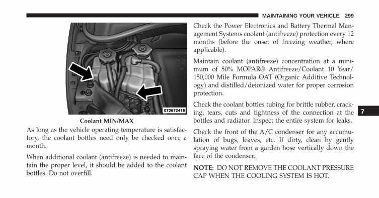
As long as the vehicle operating temperature is satisfac-tory, the coolant bottles need only be checked once amonth.
When additional coolant (antifreeze) is needed to main-tain the proper level, it should be added to the coolantbottles. Do not overfill.
Check the Power Electronics and Battery Thermal Man-agement Systems coolant (antifreeze) protection every 12months (before the onset of freezing weather, whereapplicable).
Maintain coolant (antifreeze) concentration at a mini-mum of 50% MOPAR® Antifreeze/Coolant 10 Year/150,000 Mile Formula OAT (Organic Additive Technol-ogy) and distilled/deionized water for proper corrosionprotection.
Check the coolant bottles tubing for brittle rubber, crack-ing, tears, cuts and tightness of the connection at thebottles and radiator. Inspect the entire system for leaks.
Check the front of the A/C condenser for any accumu-lation of bugs, leaves, etc. If dirty, clean by gentlyspraying water from a garden hose vertically down theface of the condenser.
NOTE: DO NOT REMOVE THE COOLANT PRESSURECAP WHEN THE COOLING SYSTEM IS HOT.
Coolant MIN/MAX
7
MAINTAINING YOUR VEHICLE 299

WARNING!
You or others can be badly burned by hot coolant(antifreeze) or steam from your radiator. If you see or
(Continued)
WARNING! (Continued)hear steam coming from under the hood, do not openthe hood until the radiator has had time to cool.Never try to open a cooling system pressure capwhen the radiator is hot.
Power Electronics and Battery ThermalManagement Systems — Cooling Pressure Caps
The caps must be fully tightened to prevent loss ofcoolant (antifreeze).
The caps should be inspected and cleaned if there is anyaccumulation of foreign material on the sealing surfaces.
NOTE:
• The pressure caps on the reservoirs are unique andrated at 5 PSI caps.
• Use only Mopar® replacement parts.
300 MAINTAINING YOUR VEHICLE

WARNING!
• The warning words “DO NOT OPEN HOT” on thecooling system pressure cap are a safety precaution.Never add coolant (antifreeze) when the coolingsystem is overheated. Do not loosen or remove thecap to cool an overheated cooling system. Heatcauses pressure to build up in the cooling system.To prevent scalding or injury, do not remove thepressure cap while the system is hot or underpressure.
• Do not use a pressure cap other than the onespecified for your vehicle. Personal injury or ve-hicle damage may result.
Selection Of Coolant
Refer to “Fluids, Lubricants, and Genuine Parts” in“Maintaining Your Vehicle” for further information.
CAUTION!
• Mixing of coolant (antifreeze) other than specifiedOrganic Additive Technology (OAT) coolant (anti-freeze), may result in cooling system damage andmay decrease corrosion protection. Organic Addi-tive Technology (OAT) coolant is different andshould not be mixed with Hybrid Organic AdditiveTechnology (HOAT) coolant (antifreeze). If a non-OAT coolant (antifreeze) is introduced into thecooling system in an emergency, it should be re-placed with the specified coolant (antifreeze) assoon as possible.
• Do not use water alone or alcohol-based coolant(antifreeze) products. Do not use additional rustinhibitors or antirust products, as they may not becompatible with the radiator coolant and may plugthe radiator.
(Continued)
7
MAINTAINING YOUR VEHICLE 301
CAUTION! (Continued)• This vehicle has not been designed for use with
propylene glycol-based coolant (antifreeze). Use ofpropylene glycol-based coolant (antifreeze) is notrecommended.
Adding Coolant
Your vehicle has been built with cooling systems thatallow extended maintenance intervals. This coolant (an-tifreeze) can be used up to ten years or 150,000 miles(240,000 km) before replacement. To prevent reducingthis extended maintenance period, it is important thatyou use the same coolant (antifreeze) throughout the lifeof your vehicle.
Please review these recommendations for using OrganicAdditive Technology (OAT) coolant (antifreeze).
When adding coolant (antifreeze):
• The manufacturer recommends using MOPAR®Antifreeze/Coolant 10 Year/150,000 Mile FormulaOAT (Organic Additive Technology).
• Mix a minimum solution of 50% OAT coolant (anti-freeze) and distilled water. Use higher concentrations(not to exceed 70%) if temperatures below -34ºF (-37ºC)are anticipated.
• Use only high purity water such as distilled or deion-ized water when mixing the water and coolant (anti-freeze) solution. The use of lower quality water willreduce the amount of corrosion protection in thecooling systems.
Please note that it is the owner’s responsibility to main-tain the proper level of protection against freezing ac-cording to the temperatures occurring in the area wherethe vehicle is operated.
302 MAINTAINING YOUR VEHICLE
NOTE: Mixing coolant (antifreeze) types will decreasethe life of the Power Electronics and Battery ThermalManagement Systems coolant (antifreeze) and will re-quire more frequent coolant (antifreeze) changes.
Power Electronics and Battery ThermalManagement Systems — Drain, Flush And Refill
Refer to “Maintenance Schedules” in Section 7 of thissupplement for the proper maintenance intervals.
If the coolant (antifreeze) is dirty or contains a consider-able amount of sediment, clean and flush with a reliablecooling system cleaner. Follow with a thorough rinsing toremove all deposits and chemicals. Properly dispose ofold coolant (antifreeze) solution.
CAUTION!
It is recommended to have the cooling systems ser-viced at your authorized dealer. Failure to do so couldresult in poor cooling system performance and/orvehicle damage.
Disposal Of Used Power Electronics and BatteryThermal Management Systems Coolant
Used antifreeze is a regulated substance requiring properdisposal. Check with your local authorities to determinethe disposal rules for your community. To prevent inges-tion by animals or children, do not store antifreeze inopen containers or allow it to remain in puddles on theground. If ingested by a child, contact a physicianimmediately. Clean up any ground spills immediately.
7
MAINTAINING YOUR VEHICLE 303
Points To Remember
If an examination of your underhood compartmentshows no evidence of cooler or hose leaks, the vehiclemay be safely driven.
• Do not overfill the coolant recovery bottles.
• Check coolant (antifreeze) freeze point in the coolantrecovery bottles. If coolant (antifreeze) needs to beadded, contents of coolant recovery bottles must alsobe protected against freezing.
• If frequent coolant (antifreeze) additions are required,or if the level in the coolant recovery bottles does notdrop when the engine cools, the cooling system shouldbe pressure tested for leaks.
• Maintain coolant (antifreeze) concentration at 50%OAT coolant (antifreeze) (minimum) and distilled/deionized water for proper corrosion protection ofyour engine which contains aluminum components.
• Make sure that the coolant control systems recoverybottles overflow hoses are not kinked or obstructed.
• Keep the front of the coolant control systems clean. Ifyour vehicle is equipped with air conditioning, keepthe front of the condenser clean.
Maintenance-Free Battery 12 Volt
Your vehicle is equipped with a maintenance-free 12 Voltbattery. You will never have to add water, nor is periodicmaintenance required.
WARNING!
• Battery fluid is a corrosive acid solution and canburn or even blind you. Do not allow battery fluidto contact your eyes, skin, or clothing. Do not leanover a battery when attaching clamps. If acid
(Continued)
304 MAINTAINING YOUR VEHICLE
WARNING! (Continued)splashes in eyes or on skin, flush the area imme-diately with large amounts of water. Refer to“Jump-Starting Procedures” in “What To Do InEmergencies” for further information.
• Battery gas is flammable and explosive. Keepflame or sparks away from the battery. Do not usea booster battery or any other booster source withan output greater than 12 Volts. Do not allow cableclamps to touch each other.
• Battery posts, terminals, and related accessoriescontain lead and lead compounds. Wash handsafter handling.
• The battery in this vehicle has a vent hose thatshould not be disconnected and should only bereplaced with a battery of the same type (vented).
CAUTION!
• It is essential when replacing the cables on thebattery that the positive cable is attached to thepositive post and the negative cable is attached tothe negative post. Battery posts are marked positive(+) and negative (-) and are identified on thebattery case. Cable clamps should be tight on theterminal posts and free of corrosion.
• If a 12 Volt Low Voltage Battery System “fastcharger” is used while the battery is in the vehicle,disconnect both vehicle battery cables before con-necting the charger to the battery. Do not use a “fastcharger” to provide starting voltage.
Air Conditioner Maintenance
For best possible performance, your air conditionershould be checked and serviced by an authorized dealerat the start of each warm season. This service should
7
MAINTAINING YOUR VEHICLE 305
include cleaning of the condenser fins and air condition-ing performance tests.
CAUTION!
Do not use chemical flushes in your air conditioningsystem as the chemicals can damage your air condi-tioning components. Such damage is not covered bythe New Vehicle Limited Warranty.
WARNING!
• Use only refrigerants and compressor lubricantsapproved by the manufacturer for your air condi-tioning system. Some unapproved refrigerants areflammable and can explode, injuring you. Otherunapproved refrigerants or lubricants can cause thesystem to fail, requiring costly repairs. Refer to
(Continued)
WARNING! (Continued)Warranty Information Book, located on the DVD,for further warranty information.
• The air conditioning system contains refrigerantunder high pressure. To avoid risk of personalinjury or damage to the system, adding refrigerantor any repair requiring lines to be disconnectedshould be done by an experienced technician.
Body Lubrication
Locks and all body pivot points, including such items asseat tracks, door hinge pivot points and rollers, liftgate,tailgate, decklid, sliding doors and hood hinges, shouldbe lubricated periodically with a lithium based grease,such as MOPAR® Spray White Lube to assure quiet, easyoperation and to protect against rust and wear. Prior tothe application of any lubricant, the parts concernedshould be wiped clean to remove dust and grit; after
306 MAINTAINING YOUR VEHICLE

lubricating excess oil and grease should be removed.Particular attention should also be given to hood latchingcomponents to ensure proper function. When performingother underhood services, the hood latch, release mecha-nism and safety catch should be cleaned and lubricated.
The external lock cylinders should be lubricated twice ayear, preferably in the Fall and Spring. Apply a smallamount of a high quality lubricant, such as MOPAR®Lock Cylinder Lubricant directly into the lock cylinder.
Wiper Blades
Clean the rubber edges of the wiper blades and thewindshield and rear window periodically with a spongeor soft cloth and a mild nonabrasive cleaner. This willremove accumulations of salt, waxes, or road film, andhelp reduce streaking and smearing.
Operation of the wipers on dry glass for long periodsmay cause deterioration of the wiper blades. Always usewasher fluid when using the wipers to remove salt or dirtfrom a dry windshield or rear window.
Avoid using the wiper blades to remove frost or ice fromthe windshield or rear window. Make sure that they arenot frozen to the glass before turning them on to avoiddamaging the blade. Keep the blade rubber out of contactwith petroleum products.
NOTE: Life expectancy of wiper blades varies depend-ing on geographical area and frequency of use. Poorperformance of blades may be present with chattering,marks, water lines or wet spots. If any of these conditionsare present, clean the wiper blades or replace as neces-sary.
7
MAINTAINING YOUR VEHICLE 307
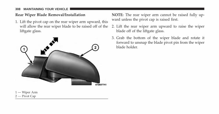
Rear Wiper Blade Removal/Installation
1. Lift the pivot cap on the rear wiper arm upward, thiswill allow the rear wiper blade to be raised off of theliftgate glass.
NOTE: The rear wiper arm cannot be raised fully up-ward unless the pivot cap is raised first.
2. Lift the rear wiper arm upward to raise the wiperblade off of the liftgate glass.
3. Grab the bottom of the wiper blade and rotate itforward to unsnap the blade pivot pin from the wiperblade holder.
1 — Wiper Arm2 — Pivot Cap
308 MAINTAINING YOUR VEHICLE

4. Install the wiper blade pivot pin into the wiper bladeholder at the end of the wiper arm, and firmly pressthe wiper blade until it snaps into place.
5. Lower the wiper blade and snap the pivot cap intoplace.
Adding Washer Fluid
The windshield washer fluid reservoir is located in theunderhood compartment, and the fluid level should bechecked at regular intervals. Fill the reservoir with wind-shield washer solvent (not coolant/ antifreeze). Refer to“Underhood Compartment” in “Maintaining Your Ve-hicle” for further information.
WARNING!
Commercially available windshield washer solventsare flammable. They could ignite and burn you. Caremust be exercised when filling or working aroundthe washer solution.
1 — Wiper Blade2 — Blade Pivot Pin3 — Wiper Arm4 — Wiper Blade Holder
7
MAINTAINING YOUR VEHICLE 309
Brake System
In order to assure brake system performance, all brakesystem components should be inspected periodically.Refer to the “Maintenance Schedule” for the propermaintenance intervals.
WARNING!
Riding the brakes can lead to brake failure andpossibly a collision. Driving with your foot resting orriding on the brake pedal can result in abnormallyhigh brake temperatures, excessive lining wear, andpossible brake damage. Riding the brakes may alsoreduce braking capacity in an emergency.
Brake Master Cylinder
The fluid level in the master cylinder should be checkedwhen performing under hood services, or immediately ifthe “Brake Warning Light” is on and the parking brake isnot applied.
Be sure to clean the top of the master cylinder area beforeremoving the cap. If necessary, add fluid to bring thefluid level up to the requirements described on the brakefluid reservoir. Fluid level can be expected to fall as thebrake pads wear. The brake fluid level should be checkedwhen the pads are replaced. However, low fluid levelmay be caused by a leak and a checkup may be needed.
NOTE:
Use only manufacturer’s recommended brake fluid. Re-fer to “Fluids, Lubricants, and Genuine Parts” in “Main-taining Your Vehicle” for further information.
310 MAINTAINING YOUR VEHICLE
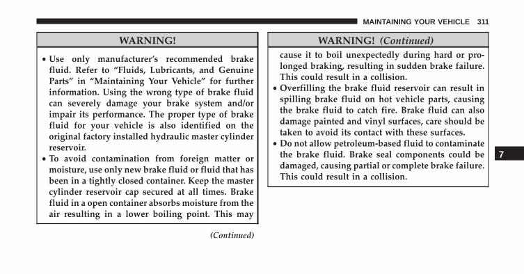
WARNING!
• Use only manufacturer’s recommended brakefluid. Refer to “Fluids, Lubricants, and GenuineParts” in “Maintaining Your Vehicle” for furtherinformation. Using the wrong type of brake fluidcan severely damage your brake system and/orimpair its performance. The proper type of brakefluid for your vehicle is also identified on theoriginal factory installed hydraulic master cylinderreservoir.
• To avoid contamination from foreign matter ormoisture, use only new brake fluid or fluid that hasbeen in a tightly closed container. Keep the mastercylinder reservoir cap secured at all times. Brakefluid in a open container absorbs moisture from theair resulting in a lower boiling point. This may
(Continued)
WARNING! (Continued)cause it to boil unexpectedly during hard or pro-longed braking, resulting in sudden brake failure.This could result in a collision.
• Overfilling the brake fluid reservoir can result inspilling brake fluid on hot vehicle parts, causingthe brake fluid to catch fire. Brake fluid can alsodamage painted and vinyl surfaces, care should betaken to avoid its contact with these surfaces.
• Do not allow petroleum-based fluid to contaminatethe brake fluid. Brake seal components could bedamaged, causing partial or complete brake failure.This could result in a collision.
7
MAINTAINING YOUR VEHICLE 311
CAUTION!
Use of improper brake fluids will affect overallclutch system performance. Improper brake fluidsmay damage the clutch system resulting in loss ofclutch function and the ability to shift the transmis-sion.
Appearance Care And Protection From Corrosion
Protection Of Body And Paint From Corrosion
Vehicle body care requirements vary according to geo-graphic locations and usage. Chemicals that make roadspassable in snow and ice and those that are sprayed ontrees and road surfaces during other seasons are highlycorrosive to the metal in your vehicle. Outside parking,which exposes your vehicle to airborne contaminants,road surfaces on which the vehicle is operated, extreme
hot or cold weather and other extreme conditions willhave an adverse effect on paint, metal trim, and under-body protection.
The following maintenance recommendations will enableyou to obtain maximum benefit from the corrosionresistance built into your vehicle.
What Causes Corrosion?
Corrosion is the result of deterioration or removal ofpaint and protective coatings from your vehicle.
The most common causes are:
• Road salt, dirt and moisture accumulation.
• Stone and gravel impact.
• Insects, tree sap and tar.
• Salt in the air near seacoast localities.
• Atmospheric fallout/industrial pollutants.
312 MAINTAINING YOUR VEHICLE
Washing
• Wash your vehicle regularly. Always wash your ve-hicle in the shade using MOPAR® Car Wash, or a mildcar wash soap, and rinse the panels completely withclear water.
• If insects, tar, or other similar deposits have accumu-lated on your vehicle, use MOPAR® Super Kleen Bugand Tar Remover to remove.
• Use a high quality cleaner wax, such as MOPAR®Cleaner Wax to remove road film, stains and to protectyour paint finish. Take care never to scratch the paint.
• Avoid using abrasive compounds and power buffingthat may diminish the gloss or thin out the paint finish.
CAUTION!
• Do not use abrasive or strong cleaning materialssuch as steel wool or scouring powder that willscratch metal and painted surfaces.
• Use of power washers exceeding 1,200 psi (8 274 kPa)can result in damage or removal of paint and decals.
Special Care
• If you drive on salted or dusty roads or if you drivenear the ocean, hose off the undercarriage at least oncea month.
• It is important that the drain holes in the lower edgesof the doors, rocker panels, and trunk be kept clear andopen.
• If you detect any stone chips or scratches in the paint,touch them up immediately. The cost of such repairs isconsidered the responsibility of the owner.
7
MAINTAINING YOUR VEHICLE 313
• If your vehicle is damaged due to a collision or similarcause that destroys the paint and protective coating,have your vehicle repaired as soon as possible. Thecost of such repairs is considered the responsibility ofthe owner.
• If you carry special cargo such as chemicals, fertilizers,de-icer salt, etc., be sure that such materials are wellpackaged and sealed.
• If a lot of driving is done on gravel roads, considermud or stone shields behind each wheel.
• Use MOPAR® Touch Up Paint on scratches as soon aspossible. Your authorized dealer has touch up paint tomatch the color of your vehicle.
Wheel And Wheel Trim Care
All wheels and wheel trim, especially aluminum andchrome plated wheels, should be cleaned regularly usingmild (neutral Ph) soap and water to maintain their lusterand to prevent corrosion. Wash wheels with the samesoap solution recommended for the body of the vehicle.
Your wheels are susceptible to deterioration caused bysalt, sodium chloride, magnesium chloride, calcium chlo-ride, etc., and other road chemicals used to melt ice orcontrol dust on dirt roads. Use a soft cloth or sponge andmild soap to wipe away promptly. Do not use harshchemicals or a stiff brush. They can damage the wheel’sprotective coating that helps keep them from corrodingand tarnishing.
NOTE: Many aftermarket wheel cleaners contain strongacids or strong alkaline additives that can harm the wheelsurface.
314 MAINTAINING YOUR VEHICLE

CAUTION!
Avoid products or automatic car washes that useacidic solutions or strong alkaline additives or harshbrushes. These products and automatic car washesmay damage the wheel’s protective finish. Suchdamage is not covered by the New Vehicle LimitedWarranty. Only car wash soap, MOPAR WheelCleaner or equivalent is recommended.
When cleaning extremely dirty wheels including exces-sive brake dust, care must be taken in the selection of tireand wheel cleaning chemicals and equipment to preventdamage to the wheels. Mopar Wheel Treatment or MoparChrome Cleaner or their equivalent is recommended orselect a non-abrasive, non-acidic cleaner for aluminum orchrome wheels. Do not use any products on Dark Vaporor Black Satin Chrome Wheels. They will permanently
damage this finish and such damage is not covered bythe New Vehicle Limited Warranty.
CAUTION!
Do not use scouring pads, steel wool, a bristle brush,metal polishes or oven cleaner. These products maydamage the wheel’s protective finish. Such damage isnot covered by the New Vehicle Limited Warranty.Only car wash soap, MOPAR Wheel Cleaner orequivalent is recommended.
NOTE: If you intend parking or storing your vehicle foran extended period after cleaning the wheels with wheelcleaner, drive your vehicle for a few minutes before doingso. Driving the vehicle and applying the brakes whenstopping will reduce the risk of brake rotor corrosion.
7
MAINTAINING YOUR VEHICLE 315

Dark Vapor Or Black Satin Chrome Wheels
CAUTION!
If your vehicle is equipped with Dark Vapor or BlackSatin Chrome wheels DO NOT USE wheel cleaners,abrasives or polishing compounds. They will perma-nently damage this finish and such damage is notcovered by the New Vehicle Limited Warranty. USEONLY MILD SOAP AND WATER WITH A SOFTCLOTH. Used on a regular basis; this is all that isrequired to maintain this finish.
Stain Repel Fabric Cleaning Procedure — IfEquipped
Stain Repel seats may be cleaned in the following manner:
• Remove as much of the stain as possible by blottingwith a clean, dry towel.
• Blot any remaining stain with a clean, damp towel.
• For tough stains, apply MOPAR® Total Clean, or amild soap solution to a clean, damp cloth and removestain. Use a fresh, damp towel to remove soap residue.
• For grease stains, apply MOPAR® Multi-PurposeCleaner to a clean, damp cloth and remove stain. Usea fresh, damp towel to remove soap residue.
• Do not use any harsh solvents or any other form ofprotectants on Stain Repel products.
Interior Care
Use MOPAR® Total Clean to clean fabric upholstery andcarpeting.
Use MOPAR® Total Clean to clean vinyl upholstery.
MOPAR® Total Clean is specifically recommended forleather upholstery.
316 MAINTAINING YOUR VEHICLE

Your leather upholstery can be best preserved by regularcleaning with a damp soft cloth. Small particles of dirtcan act as an abrasive and damage the leather upholsteryand should be removed promptly with a damp cloth.Stubborn soils can be removed easily with a soft clothand MOPAR® Total Clean. Care should be taken to avoidsoaking your leather upholstery with any liquid. Pleasedo not use polishes, oils, cleaning fluids, solvents, deter-gents, or ammonia-based cleaners to clean your leatherupholstery. Application of a leather conditioner is notrequired to maintain the original condition.
WARNING!
Do not use volatile solvents for cleaning purposes.Many are potentially flammable, and if used inclosed areas they may cause respiratory harm.
CAUTION!
Do not use Alcohol and Alcohol-based and/or Ketonbased cleaning products to clean leather seats, asdamage to the seat may result.
Cleaning Headlights
Your vehicle has plastic headlights that are lighter andless susceptible to stone breakage than glass headlights.
Plastic is not as scratch resistant as glass and thereforedifferent lens cleaning procedures must be followed.
To minimize the possibility of scratching the lenses andreducing light output, avoid wiping with a dry cloth. Toremove road dirt, wash with a mild soap solution fol-lowed by rinsing.
Do not use abrasive cleaning components, solvents, steelwool or other aggressive material to clean the lenses.
7
MAINTAINING YOUR VEHICLE 317

Glass Surfaces
All glass surfaces should be cleaned on a regular basiswith MOPAR® Glass Cleaner, or any commercialhousehold-type glass cleaner. Never use an abrasive typecleaner. Use caution when cleaning the inside rear win-dow equipped with electric defrosters or the right rearquarter window equipped with the radio antenna. Donot use scrapers or other sharp instrument that mayscratch the elements.
When cleaning the rear view mirror, spray cleaner on thetowel or rag that you are using. Do not spray cleanerdirectly on the mirror.
Instrument Panel Cover
The instrument panel cover has a low glare surface whichminimizes reflections on the windshield. Do not useprotectants or other products which may cause undesir-able reflections. Use soap and warm water to restore thelow glare surface.
Instrument Panel Bezels
CAUTION!
When installing hanging air fresheners in your ve-hicle, read the installation instructions carefully.Some air fresheners will damage the finish ofpainted or decorated parts if allowed to directlycontact any surface.
Cleaning Plastic Instrument Cluster Lenses
The lenses in front of the instruments in this vehicle aremolded in clear plastic. When cleaning the lenses, caremust be taken to avoid scratching the plastic.
1. Clean with a wet soft rag. A mild soap solution may beused, but do not use high alcohol content or abrasivecleaners. If soap is used, wipe clean with a clean damprag.
2. Dry with a soft cloth.
318 MAINTAINING YOUR VEHICLE

Seat Belt Maintenance
Do not bleach, dye or clean the belts with chemicalsolvents or abrasive cleaners. This will weaken the fabric.Sun damage can also weaken the fabric.
If the belts need cleaning, use a mild soap solution orlukewarm water. Do not remove the belts from the car towash them. Dry with a soft cloth.
Replace the belts if they appear frayed or worn or if thebuckles do not work properly.
WARNING!
A frayed or torn belt could rip apart in a collision andleave you with no protection. Inspect the belt systemperiodically, checking for cuts, frays, or loose parts.Damaged parts must be replaced immediately. Donot disassemble or modify the system. Seat belt
(Continued)
WARNING! (Continued)assemblies must be replaced after a collision if theyhave been damaged (i.e., bent retractor, torn web-bing, etc.).
FUSES
WARNING!
• When replacing a blown fuse, always use an ap-propriate replacement fuse with the same amprating as the original fuse. Never replace a fusewith another fuse of higher amp rating. Neverreplace a blown fuse with metal wires or any othermaterial. Failure to use proper fuses may result inserious personal injury, fire and/or property dam-age.
(Continued)
7
MAINTAINING YOUR VEHICLE 319
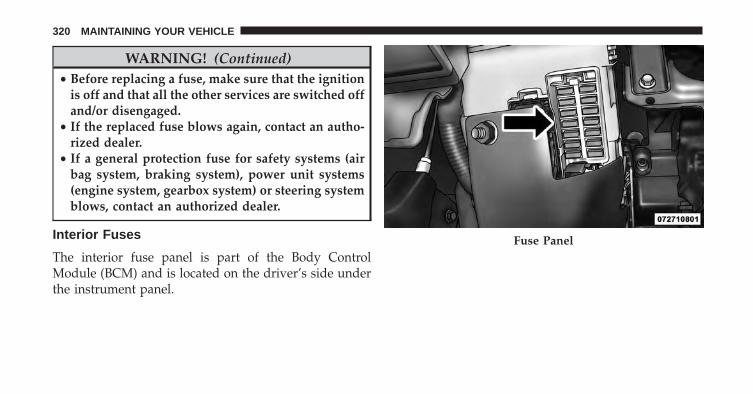
WARNING! (Continued)• Before replacing a fuse, make sure that the ignition
is off and that all the other services are switched offand/or disengaged.
• If the replaced fuse blows again, contact an autho-rized dealer.
• If a general protection fuse for safety systems (airbag system, braking system), power unit systems(engine system, gearbox system) or steering systemblows, contact an authorized dealer.
Interior Fuses
The interior fuse panel is part of the Body ControlModule (BCM) and is located on the driver’s side underthe instrument panel.
Fuse Panel
320 MAINTAINING YOUR VEHICLE

Cavity Vehicle Fuse Number Mini Fuse Description1 F12 7.5 Amp Brown Right Low Beam2 F32 5 Amp Tan Front and Rear Ceiling Lights Trunk and Door Courtesy Lights3 F53 5 Amp Tan Instrument Panel Node4 F38 20 Amp Yellow Central Door Locking5 F36 10 Amp Red Diagnostic Socket, Car Radio, Climate Control System,
Tire Pressure Monitor, TCU and CTM6 F43 20 Amp Yellow Bi-Directional Washer7 F48 20 Amp Yellow Passenger Power Window8 F13 7.5 Amp Brown Left Low Beam9 F50 7.5 Amp Brown Airbag
10 F51 5 Amp Tan Car Radio Switch, Climate Control System, Stop Light, Ex-terior Mirrors, Sunroof Switch, GPS (option) and CTM
11 F37 5 Amp Tan Stop Light Switch, Instrument Panel Node12 F49 5 Amp Tan Exterior Mirror, GPS, Electric Mirror, Parking Sensor, Sun-
roof Switch
7
MAINTAINING YOUR VEHICLE 321
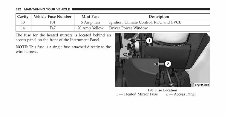
Cavity Vehicle Fuse Number Mini Fuse Description13 F31 5 Amp Tan Ignition, Climate Control, RDU and EVCU14 F47 20 Amp Yellow Driver Power Window
The fuse for the heated mirrors is located behind anaccess panel on the front of the Instrument Panel.
NOTE: This fuse is a single fuse attached directly to thewire harness.
1 — Heated Mirror Fuse 2 — Access PanelF90 Fuse Location
322 MAINTAINING YOUR VEHICLE
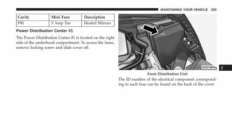
Cavity Mini Fuse DescriptionF90 5 Amp Tan Heated Mirrors
Power Distribution Center #1
The Power Distribution Center #1 is located on the rightside of the underhood compartment. To access the fuses,remove locking screw and slide cover off.
The ID number of the electrical component correspond-ing to each fuse can be found on the back of the cover.
Front Distribution Unit
7
MAINTAINING YOUR VEHICLE 323
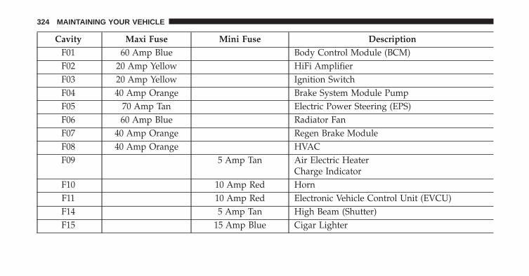
Cavity Maxi Fuse Mini Fuse DescriptionF01 60 Amp Blue Body Control Module (BCM)F02 20 Amp Yellow HiFi AmplifierF03 20 Amp Yellow Ignition SwitchF04 40 Amp Orange Brake System Module PumpF05 70 Amp Tan Electric Power Steering (EPS)F06 60 Amp Blue Radiator FanF07 40 Amp Orange Regen Brake ModuleF08 40 Amp Orange HVACF09 5 Amp Tan Air Electric Heater
Charge IndicatorF10 10 Amp Red HornF11 10 Amp Red Electronic Vehicle Control Unit (EVCU)F14 5 Amp Tan High Beam (Shutter)F15 15 Amp Blue Cigar Lighter
324 MAINTAINING YOUR VEHICLE

Cavity Maxi Fuse Mini Fuse DescriptionF16 10 Amp Red Humidity Sensor
VPAMAC Compressor
F18 5 Amp Tan Electronic Vehicle Control Unit (EVCU)F19 10 Amp Red HVACF20 15 Amp Blue Heated Seats – If EquippedF23 25 Amp Clear Anti-Lock Brake ValvesF24 7.5 Amp Brown EPS
YAW SensorF30 15 Amp Blue Fog LampsF81 30 Amp Green Electronic Shifter (ESM)F82 30 Amp Green SunroofF84 25 Amp Clear Regen Brake ModuleF85 30 Amp Green Rear Window HeaterF87 5 Amp Tan Electronic Shifter (ESM)
7
MAINTAINING YOUR VEHICLE 325
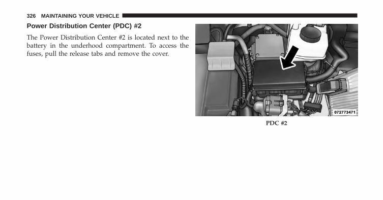
Power Distribution Center (PDC) #2
The Power Distribution Center #2 is located next to thebattery in the underhood compartment. To access thefuses, pull the release tabs and remove the cover.
PDC #2
326 MAINTAINING YOUR VEHICLE
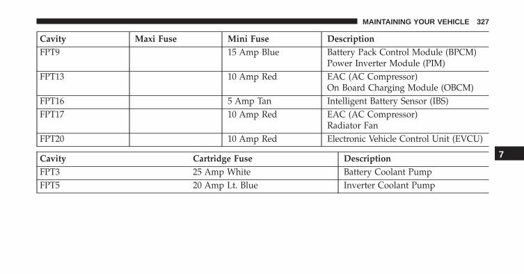
Cavity Maxi Fuse Mini Fuse DescriptionFPT9 15 Amp Blue Battery Pack Control Module (BPCM)
Power Inverter Module (PIM)FPT13 10 Amp Red EAC (AC Compressor)
On Board Charging Module (OBCM)FPT16 5 Amp Tan Intelligent Battery Sensor (IBS)FPT17 10 Amp Red EAC (AC Compressor)
Radiator FanFPT20 10 Amp Red Electronic Vehicle Control Unit (EVCU)
Cavity Cartridge Fuse DescriptionFPT3 25 Amp White Battery Coolant PumpFPT5 20 Amp Lt. Blue Inverter Coolant Pump
7
MAINTAINING YOUR VEHICLE 327
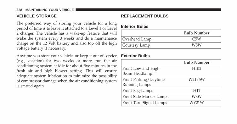
VEHICLE STORAGE
The preferred way of storing your vehicle for a longperiod of time is to leave it attached to a Level 1 or Level2 charger. The vehicle has a wake-up feature that willwake the system every 3 weeks and do a maintenancecharge on the 12 Volt battery and also top off the highvoltage battery if necessary.
Anytime you store your vehicle, or keep it out of service(e.g., vacation) for two weeks or more, run the airconditioning system at idle for about five minutes in thefresh air and high blower setting. This will ensureadequate system lubrication to minimize the possibilityof compressor damage when the air conditioning systemis started again.
REPLACEMENT BULBS
Interior Bulbs
Bulb NumberOverhead Lamp C5WCourtesy Lamp W5W
Exterior Bulbs
Bulb NumberFront Low and HighBeam Headlamp
HIR2
Front Parking/DaytimeRunning Lamps
W21/5W
Front Fog Lamps H11Front Side Marker Lamps W3WFront Turn Signal Lamps WY21W
328 MAINTAINING YOUR VEHICLE

Bulb NumberSide Direction Lamps W5WRear Turn Signal Lamps PY21WRear Side Marker Lamps W3WRear Tail and StopLamps
PY21W/5W
Rear Backup Lamps W16WCenter High MountedStop Lamp
LED (See Authorizeddealer)
License Plate Lamps LED (See Authorizeddealer)
NOTE: Numbers refer to commercial bulb types thatcan be purchased from your authorized dealer.If a bulb needs to be replaced, visit your authorizeddealer or refer to the applicable Service Manual.
BULB REPLACEMENT
NOTE: Lens fogging can occur under certain atmo-spheric conditions. This will usually clear as atmosphericconditions change to allow the condensation to changeback into a vapor. Turning the lamps on will usuallyaccelerate the clearing process.
Headlamps Low Beam and High Beam
1. Remove the plastic cap from the back of the headlamphousing.
2. Rotate the bulb counter-clockwise.
3. Remove the bulb and replace as needed.
4. Install the bulb and rotate clockwise to lock in place.
5. Reinstall the plastic cap.
7
MAINTAINING YOUR VEHICLE 329

Front Turn Signal, Parking And Daytime RunningLamps
1. Turn the steering wheel completely to the left or right.
2. Open the wheel housing access door.
3. Remove the plastic cap from the back of the lamphousing.
4. Rotate bulb/socket counter-clockwise.
5. Remove the bulb and replace as needed.
6. Install the bulb into socket, and rotate bulb/socketclockwise into lamp locking it in place.
7. Reinstall the plastic cap.
Wheel Housing Access Door
330 MAINTAINING YOUR VEHICLE

Front Fog Lamps
To replace the front fog lights, see your authorized dealer.
Front/Rear Side Marker Lamps
1. Remove portion of the wheel liner to allow handaccess to side marker lamp.
2. Rotate the bulb socket counterclockwise, and removethe bulb and socket assembly from the housing.
3. Pull the bulb from the socket and insert the replace-ment bulb.
4. Install the bulb and socket assembly into the housing,and rotate the socket clockwise to lock it in place.
5. Reinstall the wheel liner.
Rear Tail, Stop, Backup And Turn Signal Lamps
1. Open the liftgate.
2. Remove the two screws and remove the tail lampassembly.
Tail Lamp Assembly Screws
7
MAINTAINING YOUR VEHICLE 331
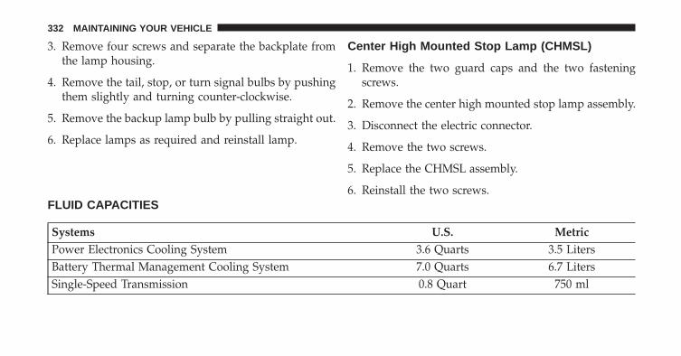
3. Remove four screws and separate the backplate fromthe lamp housing.
4. Remove the tail, stop, or turn signal bulbs by pushingthem slightly and turning counter-clockwise.
5. Remove the backup lamp bulb by pulling straight out.
6. Replace lamps as required and reinstall lamp.
Center High Mounted Stop Lamp (CHMSL)
1. Remove the two guard caps and the two fasteningscrews.
2. Remove the center high mounted stop lamp assembly.
3. Disconnect the electric connector.
4. Remove the two screws.
5. Replace the CHMSL assembly.
6. Reinstall the two screws.FLUID CAPACITIES
Systems U.S. MetricPower Electronics Cooling System 3.6 Quarts 3.5 LitersBattery Thermal Management Cooling System 7.0 Quarts 6.7 LitersSingle-Speed Transmission 0.8 Quart 750 ml
332 MAINTAINING YOUR VEHICLE

FLUIDS, LUBES, AND GENUINE PARTS
Component Fluid, Lubricant, or Genuine PartCoolant MOPAR® Antifreeze/Coolant 10 Year/150,000 Mile
Formula OAT (Organic Additive Technology) orequivalent meeting the requirements of Chrysler
Material Standard MS-12106.Brake Master Cylinder MOPAR® DOT 3, SAE J1703 should be used. If DOT
3, SAE J1703 brake fluid is not available, then DOT 4is acceptable. Use only recommended brake fluids or
equivalent.Refrigerant MOPAR® R134a
Compressor Lubricant MOPAR® POE Oil or Equivalent meeting the require-ments of Chrysler Material Standard MS-12727
Single-Speed Transmission Castrol BOT 533
7
MAINTAINING YOUR VEHICLE 333

MAINTENANCE SCHEDULES
CONTENTS� MAINTENANCE SCHEDULE . . . . . . . . . . . . .336 ▫ Maintenance Chart . . . . . . . . . . . . . . . . . . . .336
8

MAINTENANCE SCHEDULE
Once A Month Or Before A Trip:
• Check windshield washer fluid level
• Check the tire inflation pressures and look for unusualwear or damage
• Check the fluid levels of the coolant reservoirs andbrake master cylinder
• Check function of all interior and exterior lights
Required Maintenance Intervals
Refer to the maintenance schedules on the followingpage for the required maintenance intervals.
At Every Service Interval:• Rotate the tires. Rotate at the first sign of irregu-
lar wear.• Inspect brake pads, shoes, rotors, drums, and
hoses.• Inspect battery cooling system protection and
hoses.• Check and adjust hand brake.
Maintenance Chart
Refer to the Maintenance Schedules on the followingpages for the required maintenance intervals.
336 MAINTENANCE SCHEDULES

Mileage or time passed (whichever comes first)
20,0
00
30,0
00
40,0
00
50,0
00
60,0
00
70,0
00
80,0
00
90,0
00
100,
000
110,
000
120,
000
130,
000
140,
000
150,
000
Or Years: 2 3 4 5 6 7 8 9 10 11 12 13 14 15Or Kilometers:
32,0
00
48,0
00
64,0
00
80,0
00
96,0
00
112,
000
128,
000
144,
000
160,
000
176,
000
192,
000
208,
000
224,
000
240,
000
Additional InspectionsInspect the CV joints. X X X X XInspect front suspension, tie rod ends and bootseals, and replace if necessary. X X X X X X X
Inspect the brake linings. Replace as necessary. X X X X X X XInspect parking brake function. Adjust as necessary. X X X X X X XAdditional MaintenanceReplace cabin air filter. X X X X X X XClean and lube sun roof tracks. X X X X X X XFlush and replace the Power Electronics and Bat-tery Thermal Loop Systems at 10 years or 150,000miles (240,000 km) whichever comes first.
X X
8
MAINTENANCE SCHEDULES 337
WARNING!
• You can be badly injured working on or around amotor vehicle. Do only service work for which youhave the knowledge and the right equipment. Ifyou have any doubt about your ability to perform aservice job, take your vehicle to a competent me-chanic.
• Failure to properly inspect and maintain your ve-hicle could result in a component malfunction andeffect vehicle handling and performance. Thiscould cause an accident.
338 MAINTENANCE SCHEDULES

IF YOU NEED CONSUMER ASSISTANCE
CONTENTS� SUGGESTIONS FOR OBTAINING SERVICE
FOR YOUR VEHICLE . . . . . . . . . . . . . . . . . . .340
▫ Prepare For The Appointment. . . . . . . . . . . . .340
▫ Prepare A List . . . . . . . . . . . . . . . . . . . . . . . .340
▫ Be Reasonable With Requests . . . . . . . . . . . . .340
� IF YOU NEED ASSISTANCE . . . . . . . . . . . . . .340
▫ FIAT Customer Center . . . . . . . . . . . . . . . . . .341
▫ FIAT Canada Customer Center . . . . . . . . . . . .341
▫ Customer Assistance For The Hearing OrSpeech Impaired (TDD/TTY) . . . . . . . . . . . . .341
▫ Service Contract . . . . . . . . . . . . . . . . . . . . . .342
� WARRANTY INFORMATION . . . . . . . . . . . . .343
� REPORTING SAFETY DEFECTS . . . . . . . . . . . .343
▫ In The 50 United States AndWashington, D.C.. . . . . . . . . . . . . . . . . . . . . .343
▫ In Canada . . . . . . . . . . . . . . . . . . . . . . . . . . .344
� PUBLICATION ORDER FORMS . . . . . . . . . . . .344
� DEPARTMENT OF TRANSPORTATIONUNIFORM TIRE QUALITY GRADES . . . . . . . .345
▫ Treadwear. . . . . . . . . . . . . . . . . . . . . . . . . . .346
▫ Traction Grades . . . . . . . . . . . . . . . . . . . . . . .346
▫ Temperature Grades. . . . . . . . . . . . . . . . . . . .346
9
SUGGESTIONS FOR OBTAINING SERVICE FORYOUR VEHICLE
Prepare For The Appointment
If you are having warranty work done, be sure to havethe right papers with you. Take your warranty folder. Allwork to be performed may not be covered by thewarranty. Discuss additional charges with the servicemanager. Keep a maintenance log of your vehicle’sservice history. This can often provide a clue to thecurrent problem.
Prepare A List
Make a written list of your vehicle’s problems or thespecific work you want done. If you’ve had an accidentor work done that is not on your maintenance log, let theservice advisor know.
Be Reasonable With Requests
If you list a number of items and you must have yourvehicle by the end of the day, discuss the situation withthe service advisor and list the items in order of priority.At many authorized dealers, you may obtain a rentalvehicle at a minimal daily charge. If you need a rental, itis advisable to make these arrangements when you callfor an appointment.
IF YOU NEED ASSISTANCE
The manufacturer and its authorized dealer are vitallyinterested in your satisfaction. We want you to be happywith our products and services.
Warranty service must be done by an authorized dealer.We strongly recommend that you take the vehicle to anauthorized dealer. They know your vehicle the best, andare most concerned that you get prompt and high qualityservice. The manufacturer’s authorized dealer have the
340 IF YOU NEED CONSUMER ASSISTANCE
facilities, factory-trained technicians, special tools, andthe latest information to ensure the vehicle is fixedcorrectly and in a timely manner.
This is why you should always talk to an authorizeddealer service manager first. Most matters can be re-solved with this process.
• If for some reason you are still not satisfied, talk to thegeneral manager or owner of the authorized dealer.They want to know if you need assistance.
• If an authorized dealer is unable to resolve the con-cern, you may contact the manufacturer’s customercenter.
Any communication to the manufacturer’s customer cen-ter should include the following information:
• Owner’s name and address
• Owner’s telephone number (home and office)
• Authorized dealer name
• Vehicle Identification Number (VIN)
• Vehicle delivery date and mileage
FIAT Customer Center
P.O. Box 21–8004 Auburn Hills, MI 48321–8004Phone: 1–800–423–6343
FIAT Canada Customer Center
P.O. Box 1621 Windsor, Ontario N9A 4H6Phone: 1–800–465–2001 (English)Phone: 1–800–387–9983 (French)
Customer Assistance For The Hearing Or SpeechImpaired (TDD/TTY)
To assist customers who have hearing difficulties, themanufacturer has installed special TDD (Telecommuni-cation Devices for the Deaf) equipment at its customercenter. Any hearing or speech impaired customer, who
9
IF YOU NEED CONSUMER ASSISTANCE 341
has access to a TDD or a conventional teletypewriter(TTY) in the United States, can communicate with themanufacturer by dialing 1–800–380–CHRY.
Canadian residents with hearing difficulties that requireassistance can use the special needs relay service offeredby Bell Canada. For TTY teletypewriter users, dial 711and for Voice callers, dial 1-800-855-0511 to connect witha Bell Relay Service operator.
Service Contract
You may have purchased a service contract for a vehicleto help protect you from the high cost of unexpectedrepairs after the manufacturer’s New Vehicle LimitedWarranty expires. The manufacturer stands behind onlythe manufacturer’s service contracts. If you purchased amanufacturer’s service contract, you will receive PlanProvisions and an Owner Identification Card in the mailwithin three weeks of the vehicle delivery date. If youhave any questions about the service contract, call the
manufacturer’s Service Contract National CustomerHotline at 1-800-521-9922 (Canadian residents, call (800)465–2001 English / (800) 387–9983 French).
The manufacturer will not stand behind any servicecontract that is not the manufacturer’s service contract. Itis not responsible for any service contract other than themanufacturer’s service contract. If you purchased a ser-vice contract that is not a manufacturer’s service contract,and you require service after the manufacturer’s NewVehicle Limited Warranty expires, please refer to thecontract documents, and contact the person listed inthose documents.
We appreciate that you have made a major investmentwhen you purchased the vehicle. An authorized dealerhas also made a major investment in facilities, tools, andtraining to assure that you are absolutely delighted withthe ownership experience. You will be pleased with theirsincere efforts to resolve any warranty issues or relatedconcerns.
342 IF YOU NEED CONSUMER ASSISTANCE
WARNING!
Engine exhaust, some of its constituents, and certainvehicle components contain, or emit, chemicalsknown to the State of California to cause cancer andbirth defects, or other reproductive harm. In addi-tion, certain fluids contained in vehicles and certainproducts of component wear contain, or emit, chemi-cals known to the State of California to cause cancerand birth defects, or other reproductive harm.
WARRANTY INFORMATION
See the Warranty Information Booklet, located on theDVD, for the terms and provisions of FCA USA LLCwarranties applicable to this vehicle and market.
REPORTING SAFETY DEFECTS
In The 50 United States And Washington, D.C.
If you believe that your vehicle has a defect that couldcause a crash or cause injury or death, you shouldimmediately inform the National Highway Traffic SafetyAdministration (NHTSA) in addition to notifying themanufacturer.
If NHTSA receives similar complaints, it may open aninvestigation, and if it finds that a safety defect exists ina group of vehicles, it may order a recall and remedycampaign. However, NHTSA cannot become involved inindividual problems between you, your authorizeddealer, and the manufacturer.
9
IF YOU NEED CONSUMER ASSISTANCE 343
To contact NHTSA, you may either call the Auto SafetyHotline toll free at 1–888–327–4236 (TTY: 1–800–424– 9153),or go to http://www.safercar.gov; or write to: Administra-tor, NHTSA, 1200 New Jersey Avenue, SE., West Building,Washington, D.C. 20590. You can also obtain otherinformation about motor vehicle safety from http://www.safercar.gov.
In Canada
If you believe that your vehicle has a safety defect, youshould contact the Customer Service Department imme-diately. Canadian customers who wish to report a safetydefect to the Canadian government should contact Trans-port Canada, Motor Vehicle Defect Investigations andRecalls at 1-800-333-0510 or go to http://www.tc.gc.ca/roadsafety/
PUBLICATION ORDER FORMS
To order the following manuals, you may use either thewebsite or the phone numbers listed below. Visa, Mas-tercard, American Express, and Discover orders are ac-cepted. If you prefer mailing your payment, please callfor an order form.
NOTE: A street address is required when orderingmanuals (no P.O. Boxes).
Service Manuals
These comprehensive Service Manuals provide the infor-mation that students and professional technicians need indiagnosing/troubleshooting, problem solving, maintain-ing, servicing, and repairing FCA US LLC vehicles. Acomplete working knowledge of the vehicle, system,and/or components is written in straightforward lan-guage with illustrations, diagrams, and charts.
344 IF YOU NEED CONSUMER ASSISTANCE
Diagnostic Procedure Manuals
Diagnostic Procedure Manuals are filled with diagrams,charts and detailed illustrations. These practical manualsmake it easy for students and technicians to find and fixproblems on computer-controlled vehicle systems andfeatures. They show exactly how to find and correctproblems the first time, using step-by-step troubleshoot-ing and drivability procedures, proven diagnostic testsand a complete list of all tools and equipment.
Owner’s Manuals
These Owner’s Manuals have been prepared with theassistance of service and engineering specialists to ac-quaint you with specific FCA US LLC vehicles. Includedare starting, operating, emergency and maintenance pro-cedures as well as specifications, capabilities and safetytips.
• Call toll free at:
1-800-890-4038 (U.S.)
1-800-387-1143 (Canada)
Or
• Visit us on the Worldwide Web at:
www.techauthority.com
DEPARTMENT OF TRANSPORTATION UNIFORMTIRE QUALITY GRADES
The following tire grading categories were established bythe National Highway Traffic Safety Administration. Thespecific grade rating assigned by the tire’s manufacturerin each category is shown on the sidewall of the tires onyour vehicle.
All passenger car tires must conform to Federal safetyrequirements in addition to these grades.
9
IF YOU NEED CONSUMER ASSISTANCE 345

Treadwear
The Treadwear grade is a comparative rating, based onthe wear rate of the tire when tested under controlledconditions on a specified government test course. Forexample, a tire graded 150 would wear one and one-halftimes as well on the government course as a tire graded100. The relative performance of tires depends upon theactual conditions of their use, however, and may departsignificantly from the norm due to variations in drivinghabits, service practices, and differences in road charac-teristics and climate.
Traction Grades
The Traction grades, from highest to lowest, are AA, A, B,and C. These grades represent the tire’s ability to stop onwet pavement, as measured under controlled conditionson specified government test surfaces of asphalt andconcrete. A tire marked C may have poor traction perfor-mance.
WARNING!
The traction grade assigned to this tire is based onstraight-ahead braking traction tests, and does notinclude acceleration, cornering, hydroplaning, orpeak traction characteristics.
Temperature Grades
The temperature grades are A (the highest), B, and C,representing the tire’s resistance to the generation of heatand its ability to dissipate heat, when tested undercontrolled conditions on a specified indoor laboratorytest wheel. Sustained high temperature can cause thematerial of the tire to degenerate and reduce tire life, andexcessive temperature can lead to sudden tire failure. Thegrade C corresponds to a level of performance, which allpassenger car tires must meet under the Federal Motor
346 IF YOU NEED CONSUMER ASSISTANCE

Vehicle Safety Standard No. 109. Grades B and A repre-sent higher levels of performance on the laboratory testwheel, than the minimum required by law.
WARNING!
The temperature grade for this tire is established fora tire that is properly inflated and not overloaded.Excessive speed, under-inflation, or excessive load-ing, either separately or in combination, can causeheat buildup and possible tire failure.
9
IF YOU NEED CONSUMER ASSISTANCE 347


INDEX
10
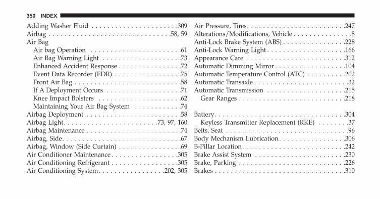
Adding Washer Fluid . . . . . . . . . . . . . . . . . . . . . .309Airbag . . . . . . . . . . . . . . . . . . . . . . . . . . . . . . .58, 59Air Bag
Air bag Operation . . . . . . . . . . . . . . . . . . . . . . .61Air Bag Warning Light . . . . . . . . . . . . . . . . . . . .73Enhanced Accident Response . . . . . . . . . . . . . . . .72Event Data Recorder (EDR) . . . . . . . . . . . . . . . . .75Front Air Bag . . . . . . . . . . . . . . . . . . . . . . . . . . .58If A Deployment Occurs . . . . . . . . . . . . . . . . . . .71Knee Impact Bolsters . . . . . . . . . . . . . . . . . . . . .62Maintaining Your Air Bag System . . . . . . . . . . . .74
Airbag Deployment . . . . . . . . . . . . . . . . . . . . . . . .58Airbag Light. . . . . . . . . . . . . . . . . . . . . . . .73, 97, 160Airbag Maintenance . . . . . . . . . . . . . . . . . . . . . . . .74Airbag, Side . . . . . . . . . . . . . . . . . . . . . . . . . . . . . .67Airbag, Window (Side Curtain) . . . . . . . . . . . . . . . .69Air Conditioner Maintenance . . . . . . . . . . . . . . . . .305Air Conditioning Refrigerant . . . . . . . . . . . . . . . . .305Air Conditioning System. . . . . . . . . . . . . . . . .202, 305
Air Pressure, Tires. . . . . . . . . . . . . . . . . . . . . . . . .247Alterations/Modifications, Vehicle . . . . . . . . . . . . . . .8Anti-Lock Brake System (ABS) . . . . . . . . . . . . . . . .228Anti-Lock Warning Light . . . . . . . . . . . . . . . . . . . .166Appearance Care . . . . . . . . . . . . . . . . . . . . . . . . .312Automatic Dimming Mirror . . . . . . . . . . . . . . . . . .104Automatic Temperature Control (ATC) . . . . . . . . . .202Automatic Transaxle . . . . . . . . . . . . . . . . . . . . . . . .32Automatic Transmission . . . . . . . . . . . . . . . . . . . .215
Gear Ranges . . . . . . . . . . . . . . . . . . . . . . . . . . .218
Battery . . . . . . . . . . . . . . . . . . . . . . . . . . . . . . . . .304Keyless Transmitter Replacement (RKE) . . . . . . . .37
Belts, Seat . . . . . . . . . . . . . . . . . . . . . . . . . . . . . . .96Body Mechanism Lubrication . . . . . . . . . . . . . . . . .306B-Pillar Location . . . . . . . . . . . . . . . . . . . . . . . . . .242Brake Assist System . . . . . . . . . . . . . . . . . . . . . . .230Brake, Parking . . . . . . . . . . . . . . . . . . . . . . . . . . .226Brakes . . . . . . . . . . . . . . . . . . . . . . . . . . . . . . . . .310
350 INDEX
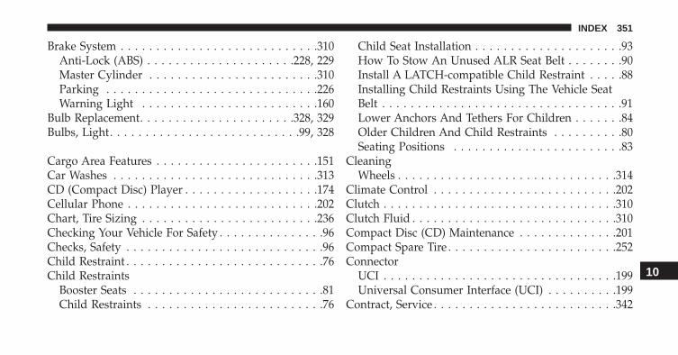
Brake System . . . . . . . . . . . . . . . . . . . . . . . . . . . .310Anti-Lock (ABS) . . . . . . . . . . . . . . . . . . . . .228, 229Master Cylinder . . . . . . . . . . . . . . . . . . . . . . . .310Parking . . . . . . . . . . . . . . . . . . . . . . . . . . . . . .226Warning Light . . . . . . . . . . . . . . . . . . . . . . . . .160
Bulb Replacement. . . . . . . . . . . . . . . . . . . . . .328, 329Bulbs, Light. . . . . . . . . . . . . . . . . . . . . . . . . . .99, 328
Cargo Area Features . . . . . . . . . . . . . . . . . . . . . . .151Car Washes . . . . . . . . . . . . . . . . . . . . . . . . . . . . .313CD (Compact Disc) Player . . . . . . . . . . . . . . . . . . .174Cellular Phone . . . . . . . . . . . . . . . . . . . . . . . . . . .202Chart, Tire Sizing . . . . . . . . . . . . . . . . . . . . . . . . .236Checking Your Vehicle For Safety . . . . . . . . . . . . . . .96Checks, Safety . . . . . . . . . . . . . . . . . . . . . . . . . . . .96Child Restraint . . . . . . . . . . . . . . . . . . . . . . . . . . . .76Child Restraints
Booster Seats . . . . . . . . . . . . . . . . . . . . . . . . . . .81Child Restraints . . . . . . . . . . . . . . . . . . . . . . . . .76
Child Seat Installation . . . . . . . . . . . . . . . . . . . . .93How To Stow An Unused ALR Seat Belt . . . . . . . .90Install A LATCH-compatible Child Restraint . . . . .88Installing Child Restraints Using The Vehicle SeatBelt . . . . . . . . . . . . . . . . . . . . . . . . . . . . . . . . . .91Lower Anchors And Tethers For Children . . . . . . .84Older Children And Child Restraints . . . . . . . . . .80Seating Positions . . . . . . . . . . . . . . . . . . . . . . . .83
CleaningWheels . . . . . . . . . . . . . . . . . . . . . . . . . . . . . . .314
Climate Control . . . . . . . . . . . . . . . . . . . . . . . . . .202Clutch . . . . . . . . . . . . . . . . . . . . . . . . . . . . . . . . .310Clutch Fluid . . . . . . . . . . . . . . . . . . . . . . . . . . . . .310Compact Disc (CD) Maintenance . . . . . . . . . . . . . .201Compact Spare Tire . . . . . . . . . . . . . . . . . . . . . . . .252Connector
UCI . . . . . . . . . . . . . . . . . . . . . . . . . . . . . . . . .199Universal Consumer Interface (UCI) . . . . . . . . . .199
Contract, Service . . . . . . . . . . . . . . . . . . . . . . . . . .342
10
INDEX 351

Corrosion Protection . . . . . . . . . . . . . . . . . . . . . . .312Cupholders . . . . . . . . . . . . . . . . . . . . . . . . . . . . .149Customer Assistance . . . . . . . . . . . . . . . . . . . . . . .340
Data Recorder, Event . . . . . . . . . . . . . . . . . . . . . . .75Daytime Running Lights . . . . . . . . . . . . . . . . . . . .126Defroster, Windshield . . . . . . . . . . . . . . . . . . . .97, 207Door Locks . . . . . . . . . . . . . . . . . . . . . . . . . . . . . .40Door Locks, Automatic . . . . . . . . . . . . . . . . . . . . . .43Driving
Through Flowing, Rising, or Shallow StandingWater . . . . . . . . . . . . . . . . . . . . . . . . . . . . . . . .223
Electrical Power Outlets. . . . . . . . . . . . . . . . . . . . .146Electric Remote Mirrors . . . . . . . . . . . . . . . . . . . . .106Electronic Brake Control System
Brake Assist System . . . . . . . . . . . . . . . . . . . . .230Electronic Speed Control (Cruise Control) . . . . . . . .134Electronic Stability Control (ESC) . . . . . . . . . . . . . .231
Electronic Vehicle Information Center (EVIC) . . . . . .168Emergency, In Case of
Hazard Warning Flasher . . . . . . . . . . . . . . . . . .272Towing . . . . . . . . . . . . . . . . . . . . . . . . . . . . . .291
EngineCompartment . . . . . . . . . . . . . . . . . . . . . . . . . .295Starting . . . . . . . . . . . . . . . . . . . . . . . . . . . . . .214
Enhanced Accident Response Feature . . . . . . . . . . . .72Event Data Recorder . . . . . . . . . . . . . . . . . . . . . . . .75Exterior Lights . . . . . . . . . . . . . . . . . . . . . . . . . . . .99
FlashersTurn Signal . . . . . . . . . . . . . . . . . . . . . . . . . . . .99
Fog Lights . . . . . . . . . . . . . . . . . . . . . . . . . . .129, 162Freeing A Stuck Vehicle . . . . . . . . . . . . . . . . . . . . .287Fuses . . . . . . . . . . . . . . . . . . . . . . . . . . . . . . . . . .319
Gear Ranges . . . . . . . . . . . . . . . . . . . . . . . . . . . . .218General Information . . . . . . . . . . . . . . . . . . . . . . . .35
352 INDEX

General Maintenance. . . . . . . . . . . . . . . . . . . . . . .297Glass Cleaning . . . . . . . . . . . . . . . . . . . . . . . . . . .318
HazardDriving Through Flowing, Rising, or ShallowStanding Water . . . . . . . . . . . . . . . . . . . . . . . . .223
Headlights . . . . . . . . . . . . . . . . . . . . . . . . . . . . . .125Cleaning . . . . . . . . . . . . . . . . . . . . . . . . . . . . .317High Beam . . . . . . . . . . . . . . . . . . . . . . . . . . . .162Passing . . . . . . . . . . . . . . . . . . . . . . . . . . . . . .126Switch . . . . . . . . . . . . . . . . . . . . . . . . . . . . . . .126
Heated Mirrors . . . . . . . . . . . . . . . . . . . . . . . . . . .107Heated Seats. . . . . . . . . . . . . . . . . . . . . . . . . . . . .119Holder, Cup . . . . . . . . . . . . . . . . . . . . . . . . . . . . .149Hood Release . . . . . . . . . . . . . . . . . . . . . . . . . . . .122
Ignition . . . . . . . . . . . . . . . . . . . . . . . . . . . . . . . . .32Key . . . . . . . . . . . . . . . . . . . . . . . . . . . . . . .31, 32
Ignition Key Removal . . . . . . . . . . . . . . . . . . . . . . .32
Immobilizer (Sentry Key) . . . . . . . . . . . . . . . . . . . .34Information Center, Vehicle . . . . . . . . . . . . . . . . . .168Instrument Cluster . . . . . . . . . . . . . . . . . . . . . . . .160Instrument Panel and Controls . . . . . . . . . . . . . . . .157Instrument Panel Cover . . . . . . . . . . . . . . . . . . . . .318Instrument Panel Lens Cleaning . . . . . . . . . . . . . . .318Interior Appearance Care . . . . . . . . . . . . . . . . . . . .316Interior Lighting . . . . . . . . . . . . . . . . . . . . . . . . . .128
Key-In Reminder . . . . . . . . . . . . . . . . . . . . . . . . . .34Key, Replacement . . . . . . . . . . . . . . . . . . . . . . . . . .35Keys . . . . . . . . . . . . . . . . . . . . . . . . . . . . . . . . . . .31Key, Sentry (Immobilizer) . . . . . . . . . . . . . . . . . . . .34
Lane Change and Turn Signals . . . . . . . . . . . . . . . .163Lane Change Assist . . . . . . . . . . . . . . . . . . . . . . . .127Lap/Shoulder Belts. . . . . . . . . . . . . . . . . . . . . . . . .49Latches . . . . . . . . . . . . . . . . . . . . . . . . . . . . . . . . .99
Hood . . . . . . . . . . . . . . . . . . . . . . . . . . . . . . . .122
10
INDEX 353
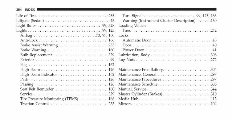
Life of Tires . . . . . . . . . . . . . . . . . . . . . . . . . . . . .255Liftgate (Sedan) . . . . . . . . . . . . . . . . . . . . . . . . . . .45Light Bulbs . . . . . . . . . . . . . . . . . . . . . . . . . . .99, 328Lights . . . . . . . . . . . . . . . . . . . . . . . . . . . . . . .99, 125
Airbag . . . . . . . . . . . . . . . . . . . . . . . . . .73, 97, 160Anti-Lock . . . . . . . . . . . . . . . . . . . . . . . . . . . . .166Brake Assist Warning . . . . . . . . . . . . . . . . . . . .233Brake Warning . . . . . . . . . . . . . . . . . . . . . . . . .160Bulb Replacement . . . . . . . . . . . . . . . . . . . . . . .329Exterior . . . . . . . . . . . . . . . . . . . . . . . . . . . . . . .99Fog . . . . . . . . . . . . . . . . . . . . . . . . . . . . . . . . .162High Beam . . . . . . . . . . . . . . . . . . . . . . . . . . . .126High Beam Indicator . . . . . . . . . . . . . . . . . . . . .162Park . . . . . . . . . . . . . . . . . . . . . . . . . . . . . . . .126Passing . . . . . . . . . . . . . . . . . . . . . . . . . . . . . .126Seat Belt Reminder . . . . . . . . . . . . . . . . . . . . . .160Service . . . . . . . . . . . . . . . . . . . . . . . . . . . . . . .329Tire Pressure Monitoring (TPMS) . . . . . . . . . . . .166Traction Control . . . . . . . . . . . . . . . . . . . . . . . .233
Turn Signal . . . . . . . . . . . . . . . . . . . . . .99, 126, 163Warning (Instrument Cluster Description) . . . . . .160
Loading VehicleTires . . . . . . . . . . . . . . . . . . . . . . . . . . . . . . . .242
LocksAutomatic Door . . . . . . . . . . . . . . . . . . . . . . . . .43Door . . . . . . . . . . . . . . . . . . . . . . . . . . . . . . . . .40Power Door . . . . . . . . . . . . . . . . . . . . . . . . . . . .41
Lubrication, Body . . . . . . . . . . . . . . . . . . . . . . . . .306Lug Nuts . . . . . . . . . . . . . . . . . . . . . . . . . . . . . . .272
Maintenance Free Battery. . . . . . . . . . . . . . . . . . . .304Maintenance, General . . . . . . . . . . . . . . . . . . . . . .297Maintenance Procedures . . . . . . . . . . . . . . . . . . . .297Maintenance Schedule . . . . . . . . . . . . . . . . . . . . . .336Manual, Service . . . . . . . . . . . . . . . . . . . . . . . . . .344Master Cylinder (Brakes) . . . . . . . . . . . . . . . . . . . .310Media Hub. . . . . . . . . . . . . . . . . . . . . . . . . . . . . .113Mirrors . . . . . . . . . . . . . . . . . . . . . . . . . . . . . . . .104
354 INDEX

Automatic Dimming . . . . . . . . . . . . . . . . . . . . .104Electric Powered . . . . . . . . . . . . . . . . . . . . . . . .106Heated . . . . . . . . . . . . . . . . . . . . . . . . . . . . . . .107
Modifications/Alterations, Vehicle . . . . . . . . . . . . . . .8Multi-Function Control Lever . . . . . . . . . . . . . . . . .125
Occupant Restraints . . . . . . . . . . . . . . . . . . . . . . . .46Occupant Restraints (Sedan) . . . . . . . . . . . . . . . .67, 69Operator Manual (Owner’s Manual) . . . . . . . . . . . . .5Owner’s Manual (Operator Manual) . . . . . . . . . .5, 344
Paint Care . . . . . . . . . . . . . . . . . . . . . . . . . . . . . .312Parking Brake. . . . . . . . . . . . . . . . . . . . . . . . . . . .226Passing Light . . . . . . . . . . . . . . . . . . . . . . . . . . . .126Pets. . . . . . . . . . . . . . . . . . . . . . . . . . . . . . . . . . . .95Placard, Tire and Loading Information . . . . . . . . . .242Power
Door Locks . . . . . . . . . . . . . . . . . . . . . . . . . . . .41Mirrors . . . . . . . . . . . . . . . . . . . . . . . . . . . . . .106
Outlet (Auxiliary Electrical Outlet) . . . . . . . . . . .146Steering . . . . . . . . . . . . . . . . . . . . . . . . . . . . . .224Sunroof . . . . . . . . . . . . . . . . . . . . . . . . . . . . . .143Windows . . . . . . . . . . . . . . . . . . . . . . . . . . . . . .43
Pregnant Women and Seat Belts . . . . . . . . . . . . . . . .54Pretensioners
Seat Belts . . . . . . . . . . . . . . . . . . . . . . . . . . . . . .55
Radial Ply Tires . . . . . . . . . . . . . . . . . . . . . . . . . .249Radio Operation. . . . . . . . . . . . . . . . . . . . . . .174, 202Radio Reception . . . . . . . . . . . . . . . . . . . . . . . . . .174Radio (Sound Systems) . . . . . . . . . . . . . . . . . . . . .174Rear Liftgate (Sedan) . . . . . . . . . . . . . . . . . . . . . . .45Rear Window Features . . . . . . . . . . . . . . . . . . . . .152Recorder, Event Data . . . . . . . . . . . . . . . . . . . . . . .75Recreational Towing . . . . . . . . . . . . . . . . . . . . . . .266Release, Hood. . . . . . . . . . . . . . . . . . . . . . . . . . . .122Reminder, Seat Belt. . . . . . . . . . . . . . . . . . . . . . . . .48
10
INDEX 355
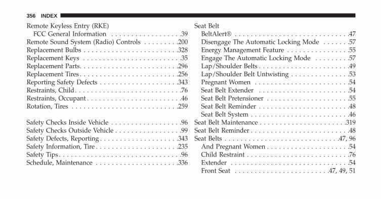
Remote Keyless Entry (RKE)FCC General Information . . . . . . . . . . . . . . . . . .39
Remote Sound System (Radio) Controls . . . . . . . . .200Replacement Bulbs . . . . . . . . . . . . . . . . . . . . . . . .328Replacement Keys . . . . . . . . . . . . . . . . . . . . . . . . .35Replacement Parts. . . . . . . . . . . . . . . . . . . . . . . . .296Replacement Tires . . . . . . . . . . . . . . . . . . . . . . . . .256Reporting Safety Defects . . . . . . . . . . . . . . . . . . . .343Restraints, Child . . . . . . . . . . . . . . . . . . . . . . . . . . .76Restraints, Occupant . . . . . . . . . . . . . . . . . . . . . . . .46Rotation, Tires . . . . . . . . . . . . . . . . . . . . . . . . . . .259
Safety Checks Inside Vehicle . . . . . . . . . . . . . . . . . .96Safety Checks Outside Vehicle . . . . . . . . . . . . . . . . .99Safety Defects, Reporting . . . . . . . . . . . . . . . . . . . .343Safety Information, Tire . . . . . . . . . . . . . . . . . . . . .235Safety Tips . . . . . . . . . . . . . . . . . . . . . . . . . . . . . . .96Schedule, Maintenance . . . . . . . . . . . . . . . . . . . . .336
Seat BeltBeltAlert® . . . . . . . . . . . . . . . . . . . . . . . . . . . . .47Disengage The Automatic Locking Mode . . . . . . .57Energy Management Feature . . . . . . . . . . . . . . . .55Engage The Automatic Locking Mode . . . . . . . . .57Lap/Shoulder Belts . . . . . . . . . . . . . . . . . . . . . . .49Lap/Shoulder Belt Untwisting . . . . . . . . . . . . . . .53Pregnant Women . . . . . . . . . . . . . . . . . . . . . . . .54Seat Belt Extender . . . . . . . . . . . . . . . . . . . . . . .54Seat Belt Pretensioner . . . . . . . . . . . . . . . . . . . . .55Seat Belt Reminder . . . . . . . . . . . . . . . . . . . . . . .48Seat Belt System . . . . . . . . . . . . . . . . . . . . . . . . .46
Seat Belt Maintenance . . . . . . . . . . . . . . . . . . . . . .319Seat Belt Reminder . . . . . . . . . . . . . . . . . . . . . . . . .48Seat Belts . . . . . . . . . . . . . . . . . . . . . . . . . . . . .47, 96
And Pregnant Women . . . . . . . . . . . . . . . . . . . . .54Child Restraint . . . . . . . . . . . . . . . . . . . . . . . . . .76Extender . . . . . . . . . . . . . . . . . . . . . . . . . . . . . .54Front Seat . . . . . . . . . . . . . . . . . . . . . . . .47, 49, 51
356 INDEX
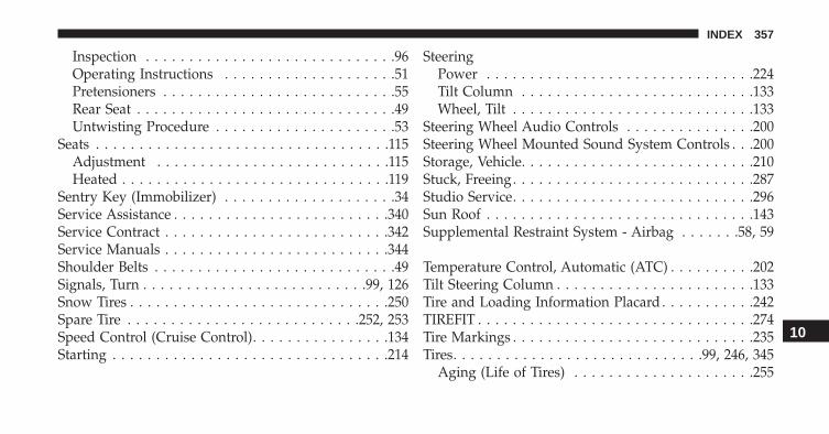
Inspection . . . . . . . . . . . . . . . . . . . . . . . . . . . . .96Operating Instructions . . . . . . . . . . . . . . . . . . . .51Pretensioners . . . . . . . . . . . . . . . . . . . . . . . . . . .55Rear Seat . . . . . . . . . . . . . . . . . . . . . . . . . . . . . .49Untwisting Procedure . . . . . . . . . . . . . . . . . . . . .53
Seats . . . . . . . . . . . . . . . . . . . . . . . . . . . . . . . . . .115Adjustment . . . . . . . . . . . . . . . . . . . . . . . . . . .115Heated . . . . . . . . . . . . . . . . . . . . . . . . . . . . . . .119
Sentry Key (Immobilizer) . . . . . . . . . . . . . . . . . . . .34Service Assistance . . . . . . . . . . . . . . . . . . . . . . . . .340Service Contract . . . . . . . . . . . . . . . . . . . . . . . . . .342Service Manuals . . . . . . . . . . . . . . . . . . . . . . . . . .344Shoulder Belts . . . . . . . . . . . . . . . . . . . . . . . . . . . .49Signals, Turn . . . . . . . . . . . . . . . . . . . . . . . . . .99, 126Snow Tires . . . . . . . . . . . . . . . . . . . . . . . . . . . . . .250Spare Tire . . . . . . . . . . . . . . . . . . . . . . . . . . .252, 253Speed Control (Cruise Control). . . . . . . . . . . . . . . .134Starting . . . . . . . . . . . . . . . . . . . . . . . . . . . . . . . .214
SteeringPower . . . . . . . . . . . . . . . . . . . . . . . . . . . . . . .224Tilt Column . . . . . . . . . . . . . . . . . . . . . . . . . . .133Wheel, Tilt . . . . . . . . . . . . . . . . . . . . . . . . . . . .133
Steering Wheel Audio Controls . . . . . . . . . . . . . . .200Steering Wheel Mounted Sound System Controls . . .200Storage, Vehicle. . . . . . . . . . . . . . . . . . . . . . . . . . .210Stuck, Freeing. . . . . . . . . . . . . . . . . . . . . . . . . . . .287Studio Service. . . . . . . . . . . . . . . . . . . . . . . . . . . .296Sun Roof . . . . . . . . . . . . . . . . . . . . . . . . . . . . . . .143Supplemental Restraint System - Airbag . . . . . . .58, 59
Temperature Control, Automatic (ATC) . . . . . . . . . .202Tilt Steering Column . . . . . . . . . . . . . . . . . . . . . . .133Tire and Loading Information Placard . . . . . . . . . . .242TIREFIT . . . . . . . . . . . . . . . . . . . . . . . . . . . . . . . .274Tire Markings . . . . . . . . . . . . . . . . . . . . . . . . . . . .235Tires. . . . . . . . . . . . . . . . . . . . . . . . . . . . .99, 246, 345
Aging (Life of Tires) . . . . . . . . . . . . . . . . . . . . .255
10
INDEX 357
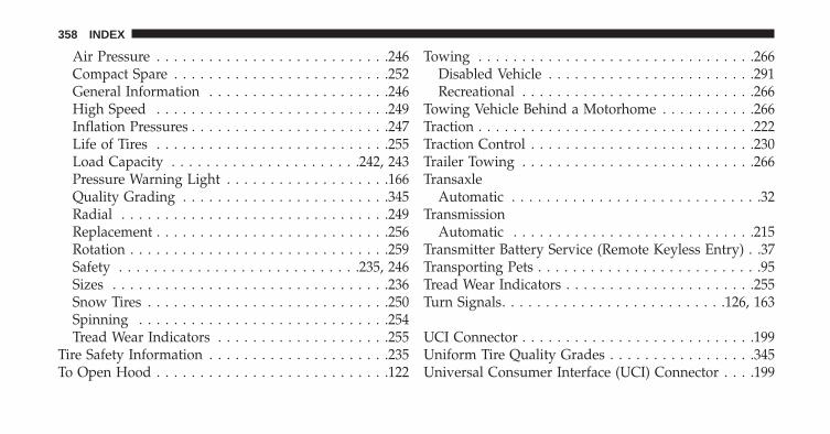
Air Pressure . . . . . . . . . . . . . . . . . . . . . . . . . . .246Compact Spare . . . . . . . . . . . . . . . . . . . . . . . . .252General Information . . . . . . . . . . . . . . . . . . . . .246High Speed . . . . . . . . . . . . . . . . . . . . . . . . . . .249Inflation Pressures . . . . . . . . . . . . . . . . . . . . . . .247Life of Tires . . . . . . . . . . . . . . . . . . . . . . . . . . .255Load Capacity . . . . . . . . . . . . . . . . . . . . . .242, 243Pressure Warning Light . . . . . . . . . . . . . . . . . . .166Quality Grading . . . . . . . . . . . . . . . . . . . . . . . .345Radial . . . . . . . . . . . . . . . . . . . . . . . . . . . . . . .249Replacement . . . . . . . . . . . . . . . . . . . . . . . . . . .256Rotation . . . . . . . . . . . . . . . . . . . . . . . . . . . . . .259Safety . . . . . . . . . . . . . . . . . . . . . . . . . . . .235, 246Sizes . . . . . . . . . . . . . . . . . . . . . . . . . . . . . . . .236Snow Tires . . . . . . . . . . . . . . . . . . . . . . . . . . . .250Spinning . . . . . . . . . . . . . . . . . . . . . . . . . . . . .254Tread Wear Indicators . . . . . . . . . . . . . . . . . . . .255
Tire Safety Information . . . . . . . . . . . . . . . . . . . . .235To Open Hood . . . . . . . . . . . . . . . . . . . . . . . . . . .122
Towing . . . . . . . . . . . . . . . . . . . . . . . . . . . . . . . .266Disabled Vehicle . . . . . . . . . . . . . . . . . . . . . . . .291Recreational . . . . . . . . . . . . . . . . . . . . . . . . . . .266
Towing Vehicle Behind a Motorhome . . . . . . . . . . .266Traction . . . . . . . . . . . . . . . . . . . . . . . . . . . . . . . .222Traction Control . . . . . . . . . . . . . . . . . . . . . . . . . .230Trailer Towing . . . . . . . . . . . . . . . . . . . . . . . . . . .266Transaxle
Automatic . . . . . . . . . . . . . . . . . . . . . . . . . . . . .32Transmission
Automatic . . . . . . . . . . . . . . . . . . . . . . . . . . . .215Transmitter Battery Service (Remote Keyless Entry) . .37Transporting Pets . . . . . . . . . . . . . . . . . . . . . . . . . .95Tread Wear Indicators . . . . . . . . . . . . . . . . . . . . . .255Turn Signals. . . . . . . . . . . . . . . . . . . . . . . . . .126, 163
UCI Connector . . . . . . . . . . . . . . . . . . . . . . . . . . .199Uniform Tire Quality Grades . . . . . . . . . . . . . . . . .345Universal Consumer Interface (UCI) Connector . . . .199
358 INDEX
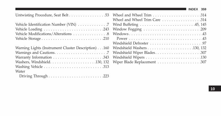
Untwisting Procedure, Seat Belt . . . . . . . . . . . . . . . .53
Vehicle Identification Number (VIN) . . . . . . . . . . . . .7Vehicle Loading . . . . . . . . . . . . . . . . . . . . . . . . . .243Vehicle Modifications/Alterations . . . . . . . . . . . . . . .8Vehicle Storage . . . . . . . . . . . . . . . . . . . . . . . . . . .210
Warning Lights (Instrument Cluster Description) . . .160Warnings and Cautions. . . . . . . . . . . . . . . . . . . . . . .7Warranty Information . . . . . . . . . . . . . . . . . . . . . .343Washers, Windshield. . . . . . . . . . . . . . . . . . . .130, 132Washing Vehicle . . . . . . . . . . . . . . . . . . . . . . . . . .313Water
Driving Through . . . . . . . . . . . . . . . . . . . . . . . .223
Wheel and Wheel Trim . . . . . . . . . . . . . . . . . . . . .314Wheel and Wheel Trim Care . . . . . . . . . . . . . . . . .314Wind Buffeting . . . . . . . . . . . . . . . . . . . . . . . .45, 145Window Fogging . . . . . . . . . . . . . . . . . . . . . . . . .209Windows . . . . . . . . . . . . . . . . . . . . . . . . . . . . . . . .43
Power . . . . . . . . . . . . . . . . . . . . . . . . . . . . . . . .43Windshield Defroster . . . . . . . . . . . . . . . . . . . . . . .97Windshield Washers . . . . . . . . . . . . . . . . . . . .130, 132Windshield Wiper Blades . . . . . . . . . . . . . . . . . . . .307Windshield Wipers . . . . . . . . . . . . . . . . . . . . . . . .130Wiper Blade Replacement . . . . . . . . . . . . . . . . . . .307
10
INDEX 359
INSTALLATION OF RADIO TRANSMITTINGEQUIPMENTSpecial design considerations are incorporated into thisvehicle’s electronic system to provide immunity to radiofrequency signals. Mobile two-way radios and telephoneequipment must be installed properly by trained person-nel. The following must be observed during installation.
The positive power connection should be made directlyto the battery and fused as close to the battery as possible.The negative power connection should be made to bodysheet metal adjacent to the negative battery connection.This connection should not be fused.
Antennas for two-way radios should be mounted on theroof or the rear area of the vehicle. Care should be usedin mounting antennas with magnet bases. Magnets mayaffect the accuracy or operation of the compass onvehicles so equipped.
The antenna cable should be as short as practical androuted away from the vehicle wiring when possible. Useonly fully shielded coaxial cable.
Carefully match the antenna and cable to the radio toensure a low Standing Wave Ratio (SWR).
Mobile radio equipment with output power greater thannormal may require special precautions.
All installations should be checked for possible interfer-ence between the communications equipment and thevehicle’s electronic systems.

O W N E R ’ S M A N U A L
2 0 1 4
20
14
FIA
T 5
00
e
14BEV24-126-AD Fourth Edition Printed in U.S.A.
FIAT 500eFCA US LLC


