32
Owner‘s Manual LED PAR SPOT with DMX input and output LED PAR 18 / 56 / 64

Owner‘s Manual
LED PAR SPOTwith DMX input and output
LED PAR 18 / 56 / 64
2
Congratulations on your purchase of this LED PAR Light.To get the most from your equipment you must read all of this manual before using it first time.
Table of Contents1. Safety Instruction ..................................................................................................32. Introduction ..........................................................................................................4
2.1 Supported function modes ...........................................................................43 Overview ................................................................................................................6
3.1 Back view ......................................................................................................63.2 DMX operation .............................................................................................7
4. Function Selection .................................................................................................75. Auto change mode ...............................................................................................8
5.1 Mode setting .................................................................................................85.1 Mode setting .................................................................................................85.3 Colour pattern setting ...................................................................................8
6. Auto fade mode ....................................................................................................96.1 Mode setting .................................................................................................96.2 Fade speed ....................................................................................................96.3 Colour pattern setting ...................................................................................9
7. Manual mode ......................................................................................................107.1 Mode setting ...............................................................................................107.2 Colour pattern setting .................................................................................10
8. DMX slave 5-channel mode ................................................................................128.1 Mode setting ...............................................................................................128.2 Speed setting ..............................................................................................128.3 DMX usage for 5-channel control ...............................................................128.4 Set up of the first DMX receiving channel ...................................................138.5 Examples .....................................................................................................13
9. DMX master 5ch mode .......................................................................................149.1 Mode setting ...............................................................................................149.2 Speed setting ..............................................................................................149.3 DMX usage for 5-channel control ...............................................................159.4 Colour pattern setting .................................................................................169.5 Examples .....................................................................................................18
10 DMX slave 3-channel .........................................................................................2210.1 Mode setting .............................................................................................2210.2 DMX usage ...............................................................................................2210.3 Set up of the first DMX receiving channel .................................................2210.4 Examples ...................................................................................................23
11 DMX Master 3-channel ......................................................................................2311.1 Mode setting .............................................................................................2411.2 Speed setting ............................................................................................2411.3 DMX usage for 3ch control .......................................................................2411.4 Colour pattern setting ...............................................................................2511.5 Examples ...................................................................................................25
12 Technical Specifications.......................................................................................2912.1 LED PAR64 and Studio PAR .......................................................................29
13. Disposal .............................................................................................................30
3
1. Safety Instruction
You have to carefully read the instruction, which includes important information about the installation, operation and maintenance.• Please keep this User Guide for future consultation. If you sell the unit
to another user, be sure that he also receives this instruction booklet thus giving them the necessary information about the use and general warnings regarding the unit.
• Unpack and check carefully there is no transportation damage before using the unit.
• Before operating, ensure that the voltage and frequency of power supply match the power requirements of the unit as stated in this manual.
• It’s important to ground the yellow/green conductor to earth in order to avoid electric shock.
• The unit is for indoor use only. Use it only in a dry location. Exposing the device to rain or moisture would cause the risk of electrical shock or fire. Maximum ambient temperature is 40°C. Don’t operate it in locations where the temperature is higher than this.
• Keep children away from this device.• The unit must be installed in a location with adequate ventilation, at
least 15 cm from adjacent surfaces. Be sure that no ventilation slots are blocked. The electrical work that is necessary for installation must be done by qualified personnel only.
• Check the surrounding area and make sure there are no flammable liquids, water or metal objects that could enter the fixture. If a foreign object or substance enters the unit, immediately disconnect the mains power.
• Disconnect the device from the mains power before any servicing or maintenance.
• In the event of serious operating problem, stop using the unit immediately. Never try to repair the unit by yourself. Repairs carried out by unskilled peo-ple can lead to damage or malfunction. Please contact the nearest author-ized technical assistance centre. Always use the same type spare parts.
• There are no user serviceable parts inside the fixture. Do not open the housing or attempt any repairs by yourself. If the fixture shows any visible damage or in the unlikely event, that your fixture may require service, please contact your nearest dealer. Always use genuine spare parts.
• Never leave this device running unattended.• Never look directly into the light source (sensitive persons may suffer an
epileptic shock).
4
2. Introduction
The main feature of this LED PAR is, that it can be used as a 4-channel DMX controller. In this mode 4 LED PARs have to be connected with XLR cables on their DMX In-/Outputs.The first LED PAR has to be set to DMX master mode. Now the LED PAR in master mode sends control signals to the connected slaves. There are different patterns available, e.g. all connected LED PARs do the same, each shows different patterns, chaser programs, fade in – fade out patterns and fade over patterns. The steps of the patterns can be controlled by music beat or by a potentiometer. The music sensitivity is controllable. The colour patterns offer a 100% colour mode, a 100% / 50% colour mode, and a 100% / 75% / 50% /25% colour mode. The colours are shown randomly.A 3-channel DMX slave mode is supported, for easy connection in a DMX system. All 512 channels are supported.The unit also supports the stand alone modes colour change, fading patterns, and fixed colour settings.
2.1 Supported function modes
2.1.1. Modes which support DMX input or DMX output
2.1.1.1 5-channel master modeIn this mode the LED PAR is used as a 4-channel DMX master. The 5-channel master mode is offered to be compatible to the first version of the LED PAR. The 5-channel master mode uses built-in functions of the LED PARs, which will be controlled by the DMX signal.There are different patterns available, e.g. all connected LED PARs do the same, each shows different patterns, chaser programs, fade in – fade out patterns and fade over patterns. The steps of the patterns can be controlled by music beat or by a potentiometer. The music sensitivity is controllable. The colour patterns offers a 100% colour mode, a 100% / 50% colour mode, and a 100% / 75% / 50% /25% colour mode. The colours are shown randomly.
2.1.1.2 3-channel master modeIn this mode the LED PAR is used as a 4-channel DMX master. The 3-channel master mode is offered for less consumption of DMX channels, e.g. in case of connected DMX power packs or other DMX receivers.
5
There are different patterns available, e.g. all connected LED PARs do the same, each shows different patterns, chaser programs, fade in – fade out patterns and fade over patterns. The steps of the patterns can be controlled by music beat or by a potentiometer. The music sensitivity is controllable. The colour patterns offers a 100% colour mode, a 100% / 50% colour mode, and a 100% / 75% / 50% /25% colour mode. The colours are shown randomly.
2.1.1.3 5-channel slave modeIn this mode the LED PAR is used as a DMX slave. The 5-channel slave mode uses build in functions, which will be controlled by the DMX signal. An external DMX controller controls the Led PAR.
2.1.1.4 3-channel slave modeThe 3-channel slave mode is for use with a standard DMX controller. The LED PAR can be controlled with all 512 channels. Each colour is controlled by one DMX channel. All 512 DMX channels can be used.
2.1.2 Stand alone modes
2.1.2.1 Auto fade modeThere is an auto fade mode available with different fade in/fade out patterns and fade over patterns. The fade in/fade out and fade over time can be set accurate by 9 time settings.The auto fade mode supports different colour change patterns: The colour patterns offer a 100% colour mode, a 100% / 50% colour mode, and a 100% / 75% / 50% /25% colour mode. The colours are shown randomly.
2.1.2.2 Auto change modeThe auto change mode supports different colour change patterns. The colour patterns offers a 100% colour mode, a 100% / 50% colour mode, and a 100% / 75% / 50% /25% colour mode. The colours are shown randomly.The change speed can be controlled by music or potentiometer.
2.1.2.3 Manual modeIn the manual mode each colour can be set to on in steps of ~14%.

6
3 Overview
3.1 Back view
This picture shows the rear panel of the LED PAR.
DMX-Input: In case of external DMX control, the DMX cable is connected here.
DMX input pin Signal1 Ground2 Signal „―“3 Signal „+“
DMX-Output: Connect the DMX cable for the next unit here.
DMX output pin Signal1 Ground2 Signal „―“3 Signal „+“
Function: This 4 pin DIP switch sets, the function mode of the LED PAR.Pattern: The function of this 10 pin DIP switch depends on the selected mode, e.g. in chaser mode the chaser patterns are selected here.Speed: Manual speed setting.Music: Sensitivity control for the build in microphone.
7
3.2 DMX operation
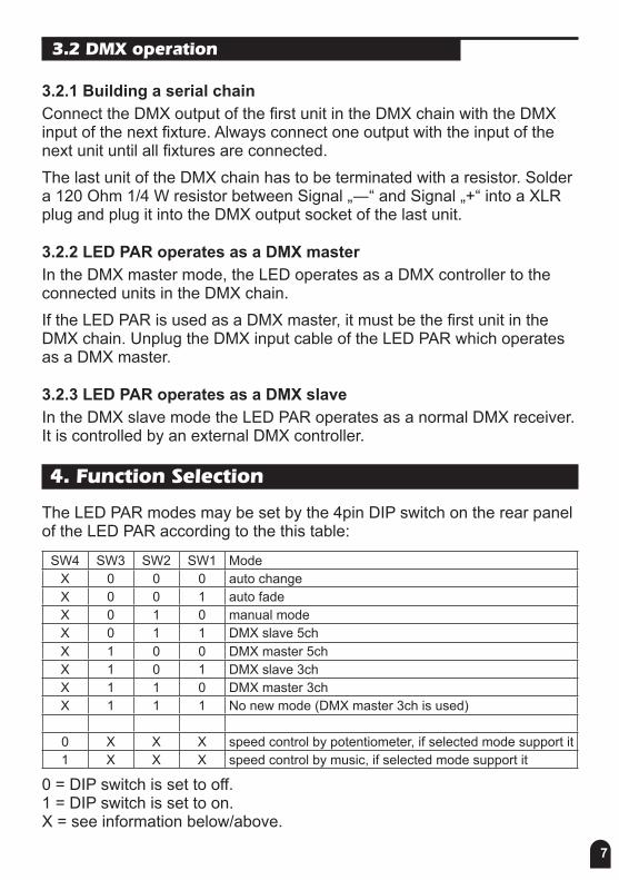
3.2.1 Building a serial chainConnect the DMX output of the first unit in the DMX chain with the DMX input of the next fixture. Always connect one output with the input of the next unit until all fixtures are connected.The last unit of the DMX chain has to be terminated with a resistor. Solder a 120 Ohm 1/4 W resistor between Signal „―“ and Signal „+“ into a XLR plug and plug it into the DMX output socket of the last unit.
3.2.2 LED PAR operates as a DMX masterIn the DMX master mode, the LED operates as a DMX controller to the connected units in the DMX chain.If the LED PAR is used as a DMX master, it must be the first unit in the DMX chain. Unplug the DMX input cable of the LED PAR which operates as a DMX master.
3.2.3 LED PAR operates as a DMX slaveIn the DMX slave mode the LED PAR operates as a normal DMX receiver. It is controlled by an external DMX controller.
4. Function Selection
The LED PAR modes may be set by the 4pin DIP switch on the rear panel of the LED PAR according to the this table:
SW4 SW3 SW2 SW1 ModeX 0 0 0 auto changeX 0 0 1 auto fadeX 0 1 0 manual modeX 0 1 1 DMX slave 5chX 1 0 0 DMX master 5chX 1 0 1 DMX slave 3chX 1 1 0 DMX master 3chX 1 1 1 No new mode (DMX master 3ch is used)
0 X X X speed control by potentiometer, if selected mode support it1 X X X speed control by music, if selected mode support it
0 = DIP switch is set to off. 1 = DIP switch is set to on. X = see information below/above.
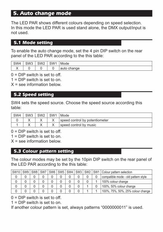
5. Auto change mode
The LED PAR shows different colours depending on speed selection. In this mode the LED PAR is used stand alone, the DMX output/input is not used.
5.1 Mode setting
To enable the auto change mode, set the 4 pin DIP switch on the rear panel of the LED PAR according to the this table:
SW4 SW3 SW2 SW1 ModeX 0 0 0 auto change
0 = DIP switch is set to off. 1 = DIP switch is set to on. X = see information below.
5.2 Speed setting
SW4 sets the speed source. Choose the speed source according this table:
SW4 SW3 SW2 SW1 Mode0 X X X speed control by potentiometer1 X X X speed control by music
0 = DIP switch is set to off. 1 = DIP switch is set to on. X = see information below.
5.3 Colour pattern setting
The colour modes may be set by the 10pin DIP switch on the rear panel of the LED PAR according to the this table:
SW10 SW9 SW8 SW7 SW6 SW5 SW4 SW3 SW2 SW1 Colour pattern selection0 0 0 0 0 0 0 0 0 0 compatible mode - old pattern style0 0 0 0 0 0 0 0 0 1 100% colour change0 0 0 0 0 0 0 0 1 0 100%, 50% colour change0 0 0 0 0 0 0 0 1 1 100%, 75%, 50%, 25% colour change
0 = DIP switch is set to off. 1 = DIP switch is set to on. If another colour pattern is set, always patterns “0000000011” is used.
9
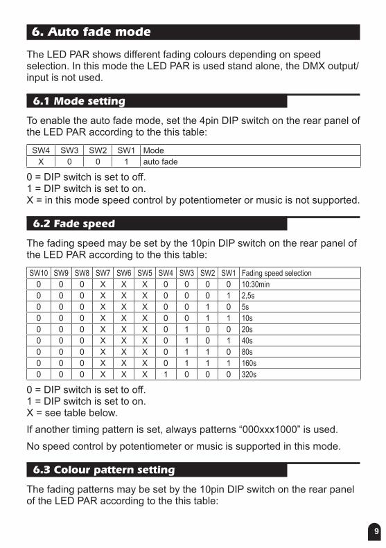
6. Auto fade mode
The LED PAR shows different fading colours depending on speed selection. In this mode the LED PAR is used stand alone, the DMX output/input is not used.
6.1 Mode setting
To enable the auto fade mode, set the 4pin DIP switch on the rear panel of the LED PAR according to the this table:
SW4 SW3 SW2 SW1 ModeX 0 0 1 auto fade
0 = DIP switch is set to off. 1 = DIP switch is set to on. X = in this mode speed control by potentiometer or music is not supported.
6.2 Fade speed
The fading speed may be set by the 10pin DIP switch on the rear panel of the LED PAR according to the this table:
SW10 SW9 SW8 SW7 SW6 SW5 SW4 SW3 SW2 SW1 Fading speed selection0 0 0 X X X 0 0 0 0 10:30min0 0 0 X X X 0 0 0 1 2,5s0 0 0 X X X 0 0 1 0 5s0 0 0 X X X 0 0 1 1 10s0 0 0 X X X 0 1 0 0 20s0 0 0 X X X 0 1 0 1 40s0 0 0 X X X 0 1 1 0 80s0 0 0 X X X 0 1 1 1 160s0 0 0 X X X 1 0 0 0 320s
0 = DIP switch is set to off. 1 = DIP switch is set to on. X = see table below.If another timing pattern is set, always patterns “000xxx1000” is used.No speed control by potentiometer or music is supported in this mode.
6.3 Colour pattern setting
The fading patterns may be set by the 10pin DIP switch on the rear panel of the LED PAR according to the this table:
10
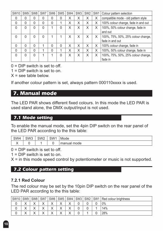
SW10 SW9 SW8 SW7 SW6 SW5 SW4 SW3 SW2 SW1 Colour pattern selection0 0 0 0 0 0 X X X X compatible mode - old pattern style0 0 0 0 0 1 X X X X 100% colour change, fade in and out0 0 0 0 1 0 X X X X 100%, 50% colour change, fade in
and out0 0 0 0 1 1 X X X X 100%, 75%, 50%, 25% colour change,
fade in and out0 0 0 1 0 0 X X X X 100% colour change, fade in0 0 0 1 0 1 X X X X 100%, 50% colour change, fade in0 0 0 1 1 0 X X X X 100%, 75%, 50%, 25% colour change,
fade in
0 = DIP switch is set to off. 1 = DIP switch is set to on. X = see table below.If another colour pattern is set, always pattern 000110xxxx is used.
7. Manual mode
The LED PAR shows different fixed colours. In this mode the LED PAR is used stand alone, the DMX output/input is not used.
7.1 Mode setting
To enable the manual mode, set the 4pin DIP switch on the rear panel of the LED PAR according to the this table:
SW4 SW3 SW2 SW1 ModeX 0 1 0 manual mode
0 = DIP switch is set to off. 1 = DIP switch is set to on. X = in this mode speed control by potentiometer or music is not supported.
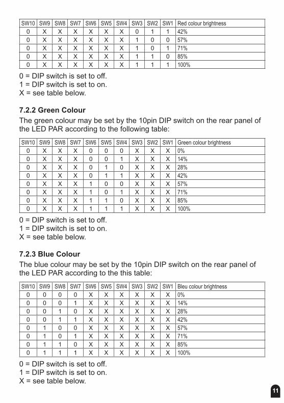
7.2 Colour pattern setting
7.2.1 Red ColourThe red colour may be set by the 10pin DIP switch on the rear panel of the LED PAR according to the this table:
SW10 SW9 SW8 SW7 SW6 SW5 SW4 SW3 SW2 SW1 Red colour brightness0 X X X X X X 0 0 0 0%0 X X X X X X 0 0 1 14%0 X X X X X X 0 1 0 28%
11
SW10 SW9 SW8 SW7 SW6 SW5 SW4 SW3 SW2 SW1 Red colour brightness0 X X X X X X 0 1 1 42%0 X X X X X X 1 0 0 57%0 X X X X X X 1 0 1 71%0 X X X X X X 1 1 0 85%0 X X X X X X 1 1 1 100%
0 = DIP switch is set to off. 1 = DIP switch is set to on. X = see table below.
7.2.2 Green ColourThe green colour may be set by the 10pin DIP switch on the rear panel of the LED PAR according to the following table:
SW10 SW9 SW8 SW7 SW6 SW5 SW4 SW3 SW2 SW1 Green colour brightness0 X X X 0 0 0 X X X 0%0 X X X 0 0 1 X X X 14%0 X X X 0 1 0 X X X 28%0 X X X 0 1 1 X X X 42%0 X X X 1 0 0 X X X 57%0 X X X 1 0 1 X X X 71%0 X X X 1 1 0 X X X 85%0 X X X 1 1 1 X X X 100%
0 = DIP switch is set to off. 1 = DIP switch is set to on. X = see table below.
7.2.3 Blue ColourThe blue colour may be set by the 10pin DIP switch on the rear panel of the LED PAR according to the this table:
SW10 SW9 SW8 SW7 SW6 SW5 SW4 SW3 SW2 SW1 Bleu colour brightness0 0 0 0 X X X X X X 0%0 0 0 1 X X X X X X 14%0 0 1 0 X X X X X X 28%0 0 1 1 X X X X X X 42%0 1 0 0 X X X X X X 57%0 1 0 1 X X X X X X 71%0 1 1 0 X X X X X X 85%0 1 1 1 X X X X X X 100%
0 = DIP switch is set to off. 1 = DIP switch is set to on. X = see table below.
12
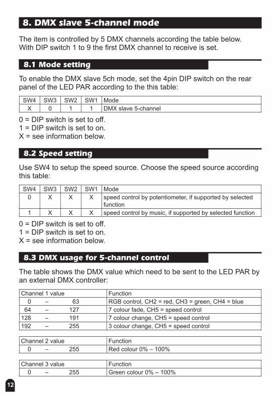
8. DMX slave 5-channel mode
The item is controlled by 5 DMX channels according the table below. With DIP switch 1 to 9 the first DMX channel to receive is set.
8.1 Mode setting
To enable the DMX slave 5ch mode, set the 4pin DIP switch on the rear panel of the LED PAR according to the this table:
SW4 SW3 SW2 SW1 ModeX 0 1 1 DMX slave 5-channel
0 = DIP switch is set to off. 1 = DIP switch is set to on. X = see information below.
8.2 Speed setting
Use SW4 to setup the speed source. Choose the speed source according this table:
SW4 SW3 SW2 SW1 Mode0 X X X speed control by potentiometer, if supported by selected
function1 X X X speed control by music, if supported by selected function
0 = DIP switch is set to off. 1 = DIP switch is set to on. X = see information below.
8.3 DMX usage for 5-channel control
The table shows the DMX value which need to be sent to the LED PAR by an external DMX controller:
Channel 1 value Function 0 – 63 RGB control, CH2 = red, CH3 = green, CH4 = blue 64 – 127 7 colour fade, CH5 = speed control128 – 191 7 colour change, CH5 = speed control192 – 255 3 colour change, CH5 = speed control
Channel 2 value Function 0 – 255 Red colour 0% – 100%
Channel 3 value Function 0 – 255 Green colour 0% – 100%
13
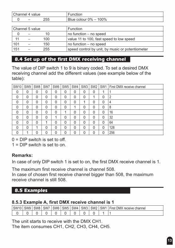
Channel 4 value Function 0 – 255 Blue colour 0% – 100%
Channel 5 value Function 0 – 10 no function – no speed 11 – 100 value 11 to 100, fast speed to low speed101 – 150 no function – no speed151 – 255 speed control by unit, by music or potentiometer
8.4 Set up of the first DMX receiving channel
The value of DIP switch 1 to 9 is binary coded. To set a desired DMX receiving channel add the different values (see example below of the table):
SW10 SW9 SW8 SW7 SW6 SW5 SW4 SW3 SW2 SW1 First DMX receive channel0 0 0 0 0 0 0 0 0 1 10 0 0 0 0 0 0 0 1 0 20 0 0 0 0 0 0 1 0 0 40 0 0 0 0 0 1 0 0 0 80 0 0 0 0 1 0 0 0 0 160 0 0 0 1 0 0 0 0 0 320 0 0 1 0 0 0 0 0 0 640 0 1 0 0 0 0 0 0 0 1280 1 0 0 0 0 0 0 0 0 256
0 = DIP switch is set to off. 1 = DIP switch is set to on.
Remarks:In case of only DIP switch 1 is set to on, the first DMX receive channel is 1.The maximum first receive channel is channel 508. In case of chosen first receive channel bigger than 508, the maximum receive channel is still 508.
8.5 Examples
8.5.3 Example A, first DMX receive channel is 1SW10 SW9 SW8 SW7 SW6 SW5 SW4 SW3 SW2 SW1 First DMX receive channel
0 0 0 0 0 0 0 0 0 1 1
The unit starts to receive with the DMX CH1. The item consumes CH1, CH2, CH3, CH4, CH5.
14
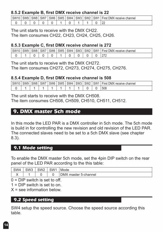
8.5.2 Example B, first DMX receive channel is 22SW10 SW9 SW8 SW7 SW6 SW5 SW4 SW3 SW2 SW1 First DMX receive channel
0 0 0 0 0 1 0 1 1 0 22
The unit starts to receive with the DMX CH22. The item consumes CH22, CH23, CH24, CH25, CH26.
8.5.3 Example C, first DMX receive channel is 272SW10 SW9 SW8 SW7 SW6 SW5 SW4 SW3 SW2 SW1 First DMX receive channel
0 1 0 0 0 1 0 0 0 0 272
The unit starts to receive with the DMX CH272. The item consumes CH272, CH273, CH274, CH275, CH276.
8.5.4 Example D, first DMX receive channel is 508SW10 SW9 SW8 SW7 SW6 SW5 SW4 SW3 SW2 SW1 First DMX receive channel
0 1 1 1 1 1 1 1 0 0 508
The unit starts to receive with the DMX CH508. The item consumes CH508, CH509, CH510, CH511, CH512.
9. DMX master 5ch mode
In this mode the LED PAR is a DMX controller in 5ch mode. The 5ch mode is build in for controlling the new revision and old revision of the LED PAR. The connected slaves need to be set to a 5ch DMX slave (see chapter 8.3).
9.1 Mode setting
To enable the DMX master 5ch mode, set the 4pin DIP switch on the rear panel of the LED PAR according to the this table:
SW4 SW3 SW2 SW1 ModeX 1 0 0 DMX master 5-channel
0 = DIP switch is set to off. 1 = DIP switch is set to on. X = see information below.
9.2 Speed setting
SW4 setup the speed source. Choose the speed source according this table.

15
SW4 SW3 SW2 SW1 Mode0 X X X speed control by potentiometer1 X X X speed control by music
0 = DIP switch is set to off. 1 = DIP switch is set to on. X = see information below.
9.3 DMX usage for 5-channel control
The LED PAR in master mode sent DMX data according to the table below. The connected slaves need to be set up to a 5channel salve (see chapter 8.3).1. DMX CH = 0, RGB control2. DMX CH = RED3. DMX CH = GREEN4. DMX CH = BLUE5. DMX CH = 0, no function, no speed
6. DMX CH = 0, RGB control7. DMX CH = RED8. DMX CH = GREEN9. DMX CH = BLUE10. DMX CH = 0, no function, no speed
11. DMX CH = 0, RGB control12. DMX CH = RED13. DMX CH = GREEN14. DMX CH = BLUE15. DMX CH = 0, no function, no speed
16. DMX CH = 0, RGB control17. DMX CH = RED18. DMX CH = GREEN19. DMX CH = BLUE20. DMX CH = 0, no function, no speed
16
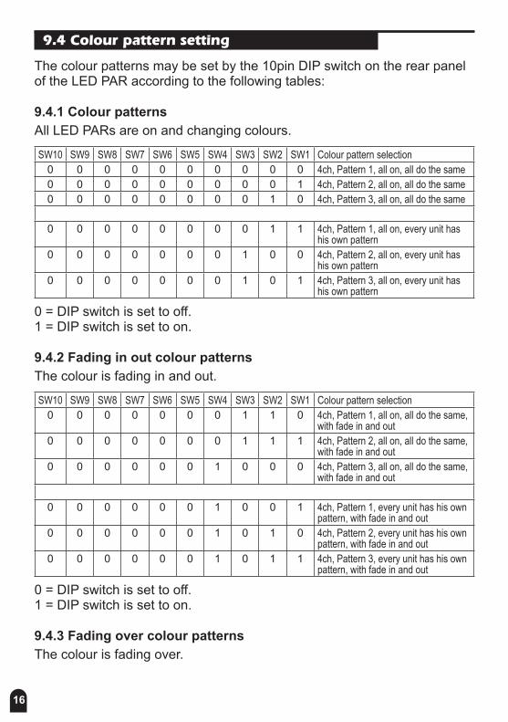
9.4 Colour pattern setting
The colour patterns may be set by the 10pin DIP switch on the rear panel of the LED PAR according to the following tables:
9.4.1 Colour patternsAll LED PARs are on and changing colours.
SW10 SW9 SW8 SW7 SW6 SW5 SW4 SW3 SW2 SW1 Colour pattern selection0 0 0 0 0 0 0 0 0 0 4ch, Pattern 1, all on, all do the same0 0 0 0 0 0 0 0 0 1 4ch, Pattern 2, all on, all do the same0 0 0 0 0 0 0 0 1 0 4ch, Pattern 3, all on, all do the same
0 0 0 0 0 0 0 0 1 1 4ch, Pattern 1, all on, every unit has his own pattern
0 0 0 0 0 0 0 1 0 0 4ch, Pattern 2, all on, every unit has his own pattern
0 0 0 0 0 0 0 1 0 1 4ch, Pattern 3, all on, every unit has his own pattern
0 = DIP switch is set to off. 1 = DIP switch is set to on.
9.4.2 Fading in out colour patternsThe colour is fading in and out.
SW10 SW9 SW8 SW7 SW6 SW5 SW4 SW3 SW2 SW1 Colour pattern selection0 0 0 0 0 0 0 1 1 0 4ch, Pattern 1, all on, all do the same,
with fade in and out0 0 0 0 0 0 0 1 1 1 4ch, Pattern 2, all on, all do the same,
with fade in and out0 0 0 0 0 0 1 0 0 0 4ch, Pattern 3, all on, all do the same,
with fade in and out
0 0 0 0 0 0 1 0 0 1 4ch, Pattern 1, every unit has his own pattern, with fade in and out
0 0 0 0 0 0 1 0 1 0 4ch, Pattern 2, every unit has his own pattern, with fade in and out
0 0 0 0 0 0 1 0 1 1 4ch, Pattern 3, every unit has his own pattern, with fade in and out
0 = DIP switch is set to off. 1 = DIP switch is set to on.
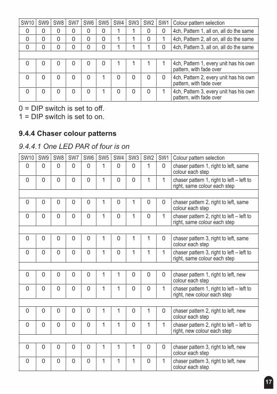
9.4.3 Fading over colour patternsThe colour is fading over.
17
SW10 SW9 SW8 SW7 SW6 SW5 SW4 SW3 SW2 SW1 Colour pattern selection0 0 0 0 0 0 1 1 0 0 4ch, Pattern 1, all on, all do the same0 0 0 0 0 0 1 1 0 1 4ch, Pattern 2, all on, all do the same0 0 0 0 0 0 1 1 1 0 4ch, Pattern 3, all on, all do the same
0 0 0 0 0 0 1 1 1 1 4ch, Pattern 1, every unit has his own pattern, with fade over
0 0 0 0 0 1 0 0 0 0 4ch, Pattern 2, every unit has his own pattern, with fade over
0 0 0 0 0 1 0 0 0 1 4ch, Pattern 3, every unit has his own pattern, with fade over
0 = DIP switch is set to off. 1 = DIP switch is set to on.
9.4.4 Chaser colour patterns
9.4.4.1 One LED PAR of four is onSW10 SW9 SW8 SW7 SW6 SW5 SW4 SW3 SW2 SW1 Colour pattern selection
0 0 0 0 0 1 0 0 1 0 chaser pattern 1, right to left, same colour each step
0 0 0 0 0 1 0 0 1 1 chaser pattern 1, right to left – left to right, same colour each step
0 0 0 0 0 1 0 1 0 0 chaser pattern 2, right to left, same colour each step
0 0 0 0 0 1 0 1 0 1 chaser pattern 2, right to left – left to right, same colour each step
0 0 0 0 0 1 0 1 1 0 chaser pattern 3, right to left, same colour each step
0 0 0 0 0 1 0 1 1 1 chaser pattern 3, right to left – left to right, same colour each step
0 0 0 0 0 1 1 0 0 0 chaser pattern 1, right to left, new colour each step
0 0 0 0 0 1 1 0 0 1 chaser pattern 1, right to left – left to right, new colour each step
0 0 0 0 0 1 1 0 1 0 chaser pattern 2, right to left, new colour each step
0 0 0 0 0 1 1 0 1 1 chaser pattern 2, right to left – left to right, new colour each step
0 0 0 0 0 1 1 1 0 0 chaser pattern 3, right to left, new colour each step
0 0 0 0 0 1 1 1 0 1 chaser pattern 3, right to left, new colour each step
18
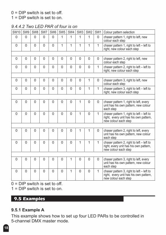
0 = DIP switch is set to off. 1 = DIP switch is set to on.
9.4.4.2 Two LED PAR of four is onSW10 SW9 SW8 SW7 SW6 SW5 SW4 SW3 SW2 SW1 Colour pattern selection
0 0 0 0 0 1 1 1 1 0 chaser pattern 1, right to left, new colour each step
0 0 0 0 0 1 1 1 1 1 chaser pattern 1, right to left – left to right, new colour each step
0 0 0 0 0 0 0 0 0 0 chaser pattern 2, right to left, new colour each step
0 0 0 0 0 0 0 0 0 1 chaser pattern 2, right to left – left to right, new colour each step
0 0 0 0 0 0 0 0 1 0 chaser pattern 3, right to left, new colour each step
0 0 0 0 0 0 0 0 1 1 chaser pattern 3, right to left – left to right, new colour each step
0 0 0 0 0 0 0 1 0 0 chaser pattern 1, right to left, every unit has his own pattern, new colour each step
0 0 0 0 0 0 0 1 0 1 chaser pattern 1, right to left – left to right, every unit has his own pattern, new colour each step
0 0 0 0 0 0 0 1 1 0 chaser pattern 2, right to left, every unit has his own pattern, new colour each step
0 0 0 0 0 0 0 1 1 1 chaser pattern 2, right to left – left to right, every unit has his own pattern, new colour each step
0 0 0 0 0 0 1 0 0 0 chaser pattern 3, right to left, every unit has his own pattern, new colour each step
0 0 0 0 0 0 1 0 0 1 chaser pattern 3, right to left – left to right, every unit has his own pattern, new colour each step
0 = DIP switch is set to off. 1 = DIP switch is set to on.
9.5 Examples
9.5.1 Example AThis example shows how to set up four LED PARs to be controlled in 5-channel DMX master mode.
19
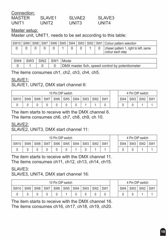
Connection:MASTER SLAVE1 SLVAE2 SLAVE3 UNIT1 UNIT2 UNIT3 UNIT4 Master setup:Master unit, UNIT1, needs to be set according to this table:
SW10 SW9 SW8 SW7 SW6 SW5 SW4 SW3 SW2 SW1 Colour pattern selection0 0 0 0 0 1 0 0 1 0 chaser pattern 1, right to left, same
colour each step
SW4 SW3 SW2 SW1 Mode0 1 0 0 DMX master 5ch, speed control by potentiometer
The items consumes ch1, ch2, ch3, ch4, ch5.SLAVE1:SLAVE1, UNIT2, DMX start channel 6:
10 Pin DIP switch 4 Pin DIP switchSW10 SW9 SW8 SW7 SW6 SW5 SW4 SW3 SW2 SW1 SW4 SW3 SW2 SW1
0 0 0 0 0 0 0 1 1 0 0 0 1 1
The item starts to receive with the DMX channel 6. The items consumes ch6, ch7, ch8, ch9, ch 10.SLAVE2:SLAVE2, UNIT3, DMX start channel 11:
10 Pin DIP switch 4 Pin DIP switchSW10 SW9 SW8 SW7 SW6 SW5 SW4 SW3 SW2 SW1 SW4 SW3 SW2 SW1
0 0 0 0 0 0 1 0 1 1 0 0 1 1
The item starts to receive with the DMX channel 11. The items consumes ch11, ch12, ch13, ch14, ch15.SLAVE3: SLAVE3, UNIT4, DMX start channel 16:
10 Pin DIP switch 4 Pin DIP switchSW10 SW9 SW8 SW7 SW6 SW5 SW4 SW3 SW2 SW1 SW4 SW3 SW2 SW1
0 0 0 0 0 1 0 0 0 0 0 0 1 1
The item starts to receive with the DMX channel 16. The items consumes ch16, ch17, ch18, ch19, ch20.
20
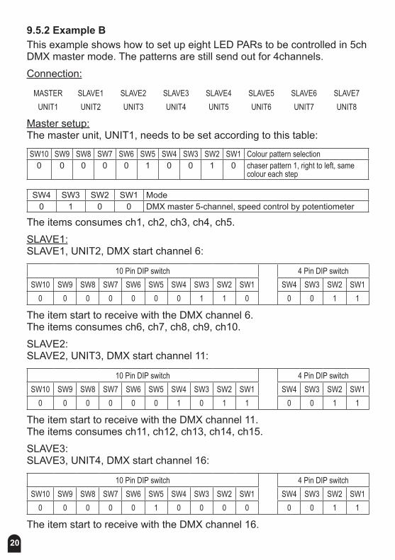
9.5.2 Example BThis example shows how to set up eight LED PARs to be controlled in 5ch DMX master mode. The patterns are still send out for 4channels.Connection:
MASTER SLAVE1 SLAVE2 SLAVE3 SLAVE4 SLAVE5 SLAVE6 SLAVE7UNIT1 UNIT2 UNIT3 UNIT4 UNIT5 UNIT6 UNIT7 UNIT8
Master setup:The master unit, UNIT1, needs to be set according to this table:
SW10 SW9 SW8 SW7 SW6 SW5 SW4 SW3 SW2 SW1 Colour pattern selection0 0 0 0 0 1 0 0 1 0 chaser pattern 1, right to left, same
colour each step
SW4 SW3 SW2 SW1 Mode0 1 0 0 DMX master 5-channel, speed control by potentiometer
The items consumes ch1, ch2, ch3, ch4, ch5.SLAVE1:SLAVE1, UNIT2, DMX start channel 6:
10 Pin DIP switch 4 Pin DIP switchSW10 SW9 SW8 SW7 SW6 SW5 SW4 SW3 SW2 SW1 SW4 SW3 SW2 SW1
0 0 0 0 0 0 0 1 1 0 0 0 1 1
The item start to receive with the DMX channel 6. The items consumes ch6, ch7, ch8, ch9, ch10.SLAVE2: SLAVE2, UNIT3, DMX start channel 11:
10 Pin DIP switch 4 Pin DIP switchSW10 SW9 SW8 SW7 SW6 SW5 SW4 SW3 SW2 SW1 SW4 SW3 SW2 SW1
0 0 0 0 0 0 1 0 1 1 0 0 1 1
The item start to receive with the DMX channel 11. The items consumes ch11, ch12, ch13, ch14, ch15.SLAVE3: SLAVE3, UNIT4, DMX start channel 16:
10 Pin DIP switch 4 Pin DIP switchSW10 SW9 SW8 SW7 SW6 SW5 SW4 SW3 SW2 SW1 SW4 SW3 SW2 SW1
0 0 0 0 0 1 0 0 0 0 0 0 1 1
The item start to receive with the DMX channel 16.

21
The items consumes ch16, ch17, ch18, ch19, ch20.SLAVE4:SLAVE4, UNIT5, DMX start channel 1:
10 Pin DIP switch 4 Pin DIP switchSW10 SW9 SW8 SW7 SW6 SW5 SW4 SW3 SW2 SW1 SW4 SW3 SW2 SW1
0 0 0 0 0 0 0 0 0 1 0 0 1 1
The item start to receive with the DMX channel 1. The items consumes ch1, ch2, ch3, ch4, ch5.SLAVE5:SLAVE5, UNIT6, DMX start channel 6:
10 Pin DIP switch 4 Pin DIP switchSW10 SW9 SW8 SW7 SW6 SW5 SW4 SW3 SW2 SW1 SW4 SW3 SW2 SW1
0 0 0 0 0 0 0 1 1 0 0 0 1 1
The item start to receive with the DMX channel 6. The items consumes ch6, ch7, ch8, ch9, ch10.SLAVE6:SLAVE6, UNIT7, DMX start channel 11:
10 Pin DIP switch 4 Pin DIP switchSW10 SW9 SW8 SW7 SW6 SW5 SW4 SW3 SW2 SW1 SW4 SW3 SW2 SW1
0 0 0 0 0 0 1 0 1 1 0 0 1 1
The item start to receive with the DMX channel 11. The items consumes ch11, ch12, ch13, ch14, ch15.SLAVE7:SLAVE7, UNIT8, DMX start channel 16:
10 Pin DIP switch 4 Pin DIP switchSW10 SW9 SW8 SW7 SW6 SW5 SW4 SW3 SW2 SW1 SW4 SW3 SW2 SW1
0 0 0 0 0 1 0 0 0 0 0 0 1 1
The item start to receive with the DMX channel 16. The items consumes ch16, ch17, ch18, ch19, ch20.
22
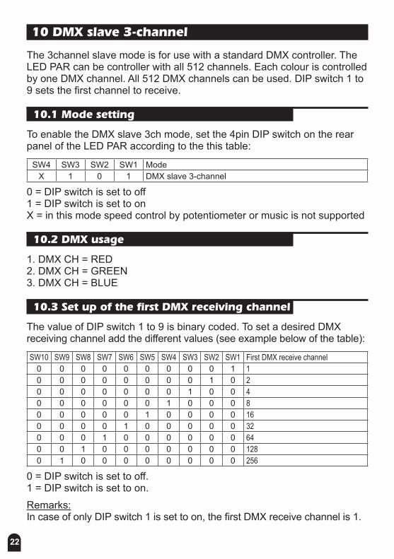
10 DMX slave 3-channel
The 3channel slave mode is for use with a standard DMX controller. The LED PAR can be controller with all 512 channels. Each colour is controlled by one DMX channel. All 512 DMX channels can be used. DIP switch 1 to 9 sets the first channel to receive.
10.1 Mode setting
To enable the DMX slave 3ch mode, set the 4pin DIP switch on the rear panel of the LED PAR according to the this table:
SW4 SW3 SW2 SW1 ModeX 1 0 1 DMX slave 3-channel
0 = DIP switch is set to off 1 = DIP switch is set to on X = in this mode speed control by potentiometer or music is not supported
10.2 DMX usage
1. DMX CH = RED 2. DMX CH = GREEN 3. DMX CH = BLUE
10.3 Set up of the first DMX receiving channel
The value of DIP switch 1 to 9 is binary coded. To set a desired DMX receiving channel add the different values (see example below of the table):
SW10 SW9 SW8 SW7 SW6 SW5 SW4 SW3 SW2 SW1 First DMX receive channel0 0 0 0 0 0 0 0 0 1 10 0 0 0 0 0 0 0 1 0 20 0 0 0 0 0 0 1 0 0 40 0 0 0 0 0 1 0 0 0 80 0 0 0 0 1 0 0 0 0 160 0 0 0 1 0 0 0 0 0 320 0 0 1 0 0 0 0 0 0 640 0 1 0 0 0 0 0 0 0 1280 1 0 0 0 0 0 0 0 0 256
0 = DIP switch is set to off. 1 = DIP switch is set to on.Remarks:In case of only DIP switch 1 is set to on, the first DMX receive channel is 1.

23
The maximum first receive channel is channel 510. In case of chosen first receive channel bigger than 510, the maximum receive channel is still 510.
10.4 Examples
10.4.1 Example A, first DMX receive channel is 1SW10 SW9 SW8 SW7 SW6 SW5 SW4 SW3 SW2 SW1 First DMX receive channel
0 0 0 0 0 0 0 0 0 1 1
The item starts to receive with the DMX CH1. The items consumes CH1, CH2, CH3.
10.4.2 Example B, first DMX receive channel is 22SW10 SW9 SW8 SW7 SW6 SW5 SW4 SW3 SW2 SW1 First DMX receive channel
0 0 0 0 0 1 0 1 1 0 22
The item starts to receive with the DMX CH22. The items consumes CH22, CH23, CH24.
10.4.3 Example C, first DMX receive channel is 272SW10 SW9 SW8 SW7 SW6 SW5 SW4 SW3 SW2 SW1 First DMX receive channel
0 1 0 0 0 1 0 1 1 0 272
The item starts to receive with the DMX CH272. The items consumes CH272, CH273, CH274.
10.4.4 Example D, first DMX receive channel is 510SW10 SW9 SW8 SW7 SW6 SW5 SW4 SW3 SW2 SW1 First DMX receive channel
0 1 1 1 1 1 1 1 1 0 510
The item starts to receive with the DMX CH510. The items consumes CH510, CH511, CH512.
11 DMX Master 3-channel
This mode has the same functions as the “DMX master 5ch” mode, chapter 9. The difference is the using of the DMX channels. In this mode only 3 DMX channels for controlling one unit are used. In this mode other units than a LED PAR can be connected e.g. a power pack, LED PARs of different companies which support control of a DMX master.
24
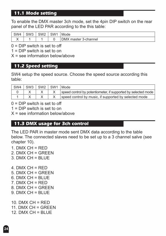
11.1 Mode setting
To enable the DMX master 3ch mode, set the 4pin DIP switch on the rear panel of the LED PAR according to the this table:
SW4 SW3 SW2 SW1 ModeX 1 1 0 DMX master 3-channel
0 = DIP switch is set to off 1 = DIP switch is set to on X = see information below/above
11.2 Speed setting
SW4 setup the speed source. Choose the speed source according this table:
SW4 SW3 SW2 SW1 Mode0 X X X speed control by potentiometer, if supported by selected mode1 X X X speed control by music, if supported by selected mode
0 = DIP switch is set to off 1 = DIP switch is set to on X = see information below/above
11.3 DMX usage for 3ch control
The LED PAR in master mode sent DMX data according to the table below. The connected slaves need to be set up to a 3 channel salve (see chapter 10).1. DMX CH = RED2. DMX CH = GREEN3. DMX CH = BLUE
4. DMX CH = RED5. DMX CH = GREEN6. DMX CH = BLUE7. DMX CH = RED8. DMX CH = GREEN9. DMX CH = BLUE
10. DMX CH = RED 11. DMX CH = GREEN 12. DMX CH = BLUE
25
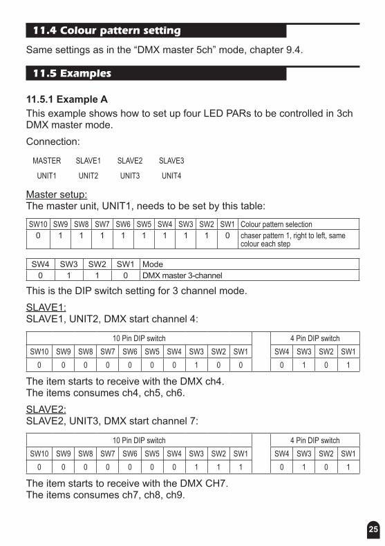
11.4 Colour pattern setting
Same settings as in the “DMX master 5ch” mode, chapter 9.4.
11.5 Examples
11.5.1 Example AThis example shows how to set up four LED PARs to be controlled in 3ch DMX master mode.Connection:
MASTER SLAVE1 SLAVE2 SLAVE3
UNIT1 UNIT2 UNIT3 UNIT4
Master setup:The master unit, UNIT1, needs to be set by this table:
SW10 SW9 SW8 SW7 SW6 SW5 SW4 SW3 SW2 SW1 Colour pattern selection0 1 1 1 1 1 1 1 1 0 chaser pattern 1, right to left, same
colour each step
SW4 SW3 SW2 SW1 Mode0 1 1 0 DMX master 3-channel
This is the DIP switch setting for 3 channel mode.SLAVE1:SLAVE1, UNIT2, DMX start channel 4:
10 Pin DIP switch 4 Pin DIP switchSW10 SW9 SW8 SW7 SW6 SW5 SW4 SW3 SW2 SW1 SW4 SW3 SW2 SW1
0 0 0 0 0 0 0 1 0 0 0 1 0 1
The item starts to receive with the DMX ch4. The items consumes ch4, ch5, ch6.SLAVE2:SLAVE2, UNIT3, DMX start channel 7:
10 Pin DIP switch 4 Pin DIP switchSW10 SW9 SW8 SW7 SW6 SW5 SW4 SW3 SW2 SW1 SW4 SW3 SW2 SW1
0 0 0 0 0 0 0 1 1 1 0 1 0 1
The item starts to receive with the DMX CH7. The items consumes ch7, ch8, ch9.
26
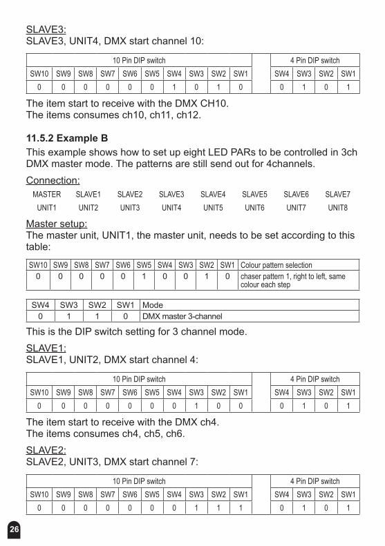
SLAVE3: SLAVE3, UNIT4, DMX start channel 10:
10 Pin DIP switch 4 Pin DIP switchSW10 SW9 SW8 SW7 SW6 SW5 SW4 SW3 SW2 SW1 SW4 SW3 SW2 SW1
0 0 0 0 0 0 1 0 1 0 0 1 0 1
The item start to receive with the DMX CH10. The items consumes ch10, ch11, ch12.
11.5.2 Example BThis example shows how to set up eight LED PARs to be controlled in 3ch DMX master mode. The patterns are still send out for 4channels.Connection:
MASTER SLAVE1 SLAVE2 SLAVE3 SLAVE4 SLAVE5 SLAVE6 SLAVE7UNIT1 UNIT2 UNIT3 UNIT4 UNIT5 UNIT6 UNIT7 UNIT8
Master setup:The master unit, UNIT1, the master unit, needs to be set according to this table:
SW10 SW9 SW8 SW7 SW6 SW5 SW4 SW3 SW2 SW1 Colour pattern selection0 0 0 0 0 1 0 0 1 0 chaser pattern 1, right to left, same
colour each step
SW4 SW3 SW2 SW1 Mode0 1 1 0 DMX master 3-channel
This is the DIP switch setting for 3 channel mode.SLAVE1:SLAVE1, UNIT2, DMX start channel 4:
10 Pin DIP switch 4 Pin DIP switchSW10 SW9 SW8 SW7 SW6 SW5 SW4 SW3 SW2 SW1 SW4 SW3 SW2 SW1
0 0 0 0 0 0 0 1 0 0 0 1 0 1
The item start to receive with the DMX ch4. The items consumes ch4, ch5, ch6.SLAVE2:SLAVE2, UNIT3, DMX start channel 7:
10 Pin DIP switch 4 Pin DIP switchSW10 SW9 SW8 SW7 SW6 SW5 SW4 SW3 SW2 SW1 SW4 SW3 SW2 SW1
0 0 0 0 0 0 0 1 1 1 0 1 0 1
27
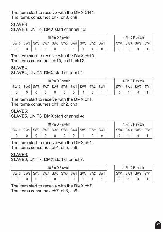
The item start to receive with the DMX CH7. The items consumes ch7, ch8, ch9.SLAVE3:SLAVE3, UNIT4, DMX start channel 10:
10 Pin DIP switch 4 Pin DIP switchSW10 SW9 SW8 SW7 SW6 SW5 SW4 SW3 SW2 SW1 SW4 SW3 SW2 SW1
0 0 0 0 0 0 1 0 1 0 0 1 0 1
The item start to receive with the DMX ch10. The items consumes ch10, ch11, ch12.SLAVE4:SLAVE4, UNIT5, DMX start channel 1:
10 Pin DIP switch 4 Pin DIP switchSW10 SW9 SW8 SW7 SW6 SW5 SW4 SW3 SW2 SW1 SW4 SW3 SW2 SW1
0 0 0 0 0 0 0 0 0 1 0 1 0 1
The item start to receive with the DMX ch1. The items consumes ch1, ch2, ch3.SLAVE5:SLAVE5, UNIT6, DMX start channel 4:
10 Pin DIP switch 4 Pin DIP switchSW10 SW9 SW8 SW7 SW6 SW5 SW4 SW3 SW2 SW1 SW4 SW3 SW2 SW1
0 0 0 0 0 0 0 1 0 0 0 1 0 1
The item start to receive with the DMX ch4. The items consumes ch4, ch5, ch6.SLAVE6:SLAVE6, UNIT7, DMX start channel 7:
10 Pin DIP switch 4 Pin DIP switchSW10 SW9 SW8 SW7 SW6 SW5 SW4 SW3 SW2 SW1 SW4 SW3 SW2 SW1
0 0 0 0 0 0 0 1 1 1 0 1 0 1
The item start to receive with the DMX ch7. The items consumes ch7, ch8, ch9.
28
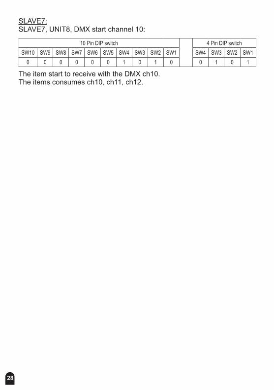
SLAVE7:SLAVE7, UNIT8, DMX start channel 10:
10 Pin DIP switch 4 Pin DIP switchSW10 SW9 SW8 SW7 SW6 SW5 SW4 SW3 SW2 SW1 SW4 SW3 SW2 SW1
0 0 0 0 0 0 1 0 1 0 0 1 0 1
The item start to receive with the DMX ch10. The items consumes ch10, ch11, ch12.
29
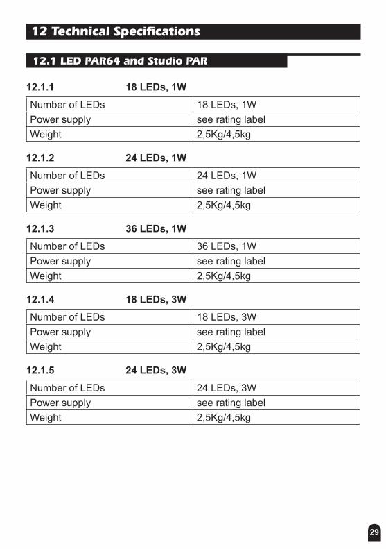
12 Technical Specifications
12.1 LED PAR64 and Studio PAR
12.1.1 18 LEDs, 1WNumber of LEDs 18 LEDs, 1WPower supply see rating labelWeight 2,5Kg/4,5kg
12.1.2 24 LEDs, 1WNumber of LEDs 24 LEDs, 1WPower supply see rating labelWeight 2,5Kg/4,5kg
12.1.3 36 LEDs, 1WNumber of LEDs 36 LEDs, 1WPower supply see rating labelWeight 2,5Kg/4,5kg
12.1.4 18 LEDs, 3WNumber of LEDs 18 LEDs, 3WPower supply see rating labelWeight 2,5Kg/4,5kg
12.1.5 24 LEDs, 3WNumber of LEDs 24 LEDs, 3WPower supply see rating labelWeight 2,5Kg/4,5kg
30
13. Disposal
Do not dispose of the device at the end of his operating life in your normal domestic waste. This device is subject to the European Guidelines 2002/96/EC.
• Have the product disposed of by a professional disposal company of by your communal disposal facility.
• Observe the currently applicable regulations. In case of doubt contact your disposal facility.
• Dispose of packaging materials in an environmentally responsible manner.

31

© 2010 Musikhaus Thomann e. K.
Treppendorf 30 • 96138 Burgebrach Germany • www.thomann.de


