Getting Ready 2Installing the Batteries 2Connecting the Equipment 2Turning the Power On 4
Basic Operation 5Adjusting the Delay 5Turning Delay On/Off 6Switching Banks/Patches 7Using the [TAP/CTL] Switch to Control the Delay 8Playing Phrase Loops 9
Editing a Patch 10
Saving a Patch 11
Parameter List 12PATCH 12CONTROL 14ASSIGN 15SYSTEM 17MIDI 17MIDI PC MAP 18
Convenient Functions 19Specifying Whether to Carry-Over the Delay Sound 19 Assigning the Functions of the [A], [B], and [TAP/CTL] Switches 19
Synchronizing with a DAW or External MIDI Device 20
Connection Example 20MIDI Messages That Can Be Transmitted and Received 20MIDI Messages That Can Only Be Received 21MIDI Routing 21
Assigning a Function to an External Pedal 22
Restoring the Factory Default Settings 24
Transmitting Data to an External MIDI Device 24
Troubleshooting 25
Main Specifications 25
USING THE UNIT SAFELY 26
IMPORTANT NOTES 26
Before using this unit, carefully read “USING THE UNIT SAFELY” and “IMPORTANT NOTES” (leaflet “USING THE UNIT SAFELY” and Owner’s Manual (p. 26)). After reading, keep the document(s) including those sections where it will be available for immediate reference.
5 High-precision 96 kHz 32-bit audio processing from input to output ensures high audio quality.
5 Easily visible delay time indication and an independent [TAP/CTL] switch provide sophisticated functionality that’s easy to use in live performance.
5 A total of 12 different delay modes, including “VINTAGE DIGITAL” that models the SDE-3000 and DD-2, as well as “ANALOG” and “TAPE.”
5 The memory function lets you store and recall 297 different setups from internal memory. “CARRY OVER” provides seamless transition that preserves the reverberant sound when switching between patches.
5 “Phrase Loop” function lets you layer new material in real time while recording and playing back. This can be used simultaneously with delay.
5 By connecting the DD-500 via a USB cable or MIDI cables, you can switch sounds and control parameters in synchronization with your computer DAW or an external MIDI device.
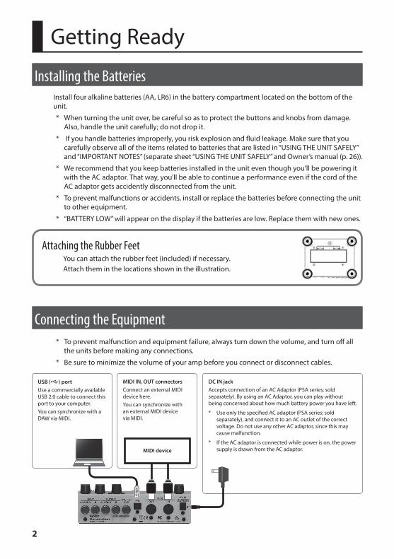
Installing the BatteriesInstall four alkaline batteries (AA, LR6) in the battery compartment located on the bottom of the unit.
* When turning the unit over, be careful so as to protect the buttons and knobs from damage. Also, handle the unit carefully; do not drop it.
* If you handle batteries improperly, you risk explosion and fluid leakage. Make sure that you carefully observe all of the items related to batteries that are listed in “USING THE UNIT SAFELY” and “IMPORTANT NOTES” (separate sheet “USING THE UNIT SAFELY” and Owner’s manual (p. 26)).
* We recommend that you keep batteries installed in the unit even though you’ll be powering it with the AC adaptor. That way, you’ll be able to continue a performance even if the cord of the AC adaptor gets accidently disconnected from the unit.
* To prevent malfunctions or accidents, install or replace the batteries before connecting the unit to other equipment.
* “BATTERY LOW” will appear on the display if the batteries are low. Replace them with new ones.
Attaching the Rubber FeetYou can attach the rubber feet (included) if necessary.Attach them in the locations shown in the illustration.
Connecting the Equipment* To prevent malfunction and equipment failure, always turn down the volume, and turn off all
the units before making any connections.
* Be sure to minimize the volume of your amp before you connect or disconnect cables.
DC IN jackAccepts connection of an AC Adaptor (PSA series; sold separately). By using an AC Adaptor, you can play without being concerned about how much battery power you have left.
* Use only the specified AC adaptor (PSA series; sold separately), and connect it to an AC outlet of the correct voltage. Do not use any other AC adaptor, since this may cause malfunction.
* If the AC adaptor is connected while power is on, the power supply is drawn from the AC adaptor.
USB (O) portUse a commercially available USB 2.0 cable to connect this port to your computer.You can synchronize with a DAW via MIDI.
MIDI IN, OUT connectorsConnect an external MIDI device here. You can synchronize with an external MIDI device via MIDI.
MIDI device
3
Getting Ready
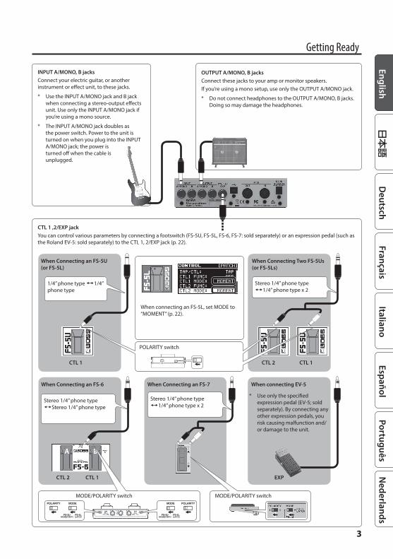
CTL 1 ,2/EXP jackYou can control various parameters by connecting a footswitch (FS-5U, FS-5L, FS-6, FS-7: sold separately) or an expression pedal (such as the Roland EV-5: sold separately) to the CTL 1, 2/EXP jack (p. 22).
INPUT A/MONO, B jacks Connect your electric guitar, or another instrument or effect unit, to these jacks.
* Use the INPUT A/MONO jack and B jack when connecting a stereo-output effects unit. Use only the INPUT A/MONO jack if you’re using a mono source.
* The INPUT A/MONO jack doubles as the power switch. Power to the unit is turned on when you plug into the INPUT A/MONO jack; the power is turned off when the cable is unplugged.
OUTPUT A/MONO, B jacksConnect these jacks to your amp or monitor speakers.If you’re using a mono setup, use only the OUTPUT A/MONO jack.
* Do not connect headphones to the OUTPUT A/MONO, B jacks. Doing so may damage the headphones.
When connecting EV-5
EXP
* Use only the specified expression pedal (EV-5; sold separately). By connecting any other expression pedals, you risk causing malfunction and/or damage to the unit.
When Connecting an FS-7
Stereo 1/4” phone type ,1/4” phone type x 2
When Connecting an FS-6
MODE/POLARITY switch
CTL 2 CTL 1
Stereo 1/4” phone type ,Stereo 1/4” phone type
MODE/POLARITY switch
When Connecting an FS-5U (or FS-5L)
When Connecting Two FS-5Us (or FS-5Ls)
1/4” phone type ,1/4” phone type
CTL 1 CTL 2 CTL 1
POLARITY switch
Stereo 1/4” phone type ,1/4” phone type x 2
When connecting an FS-5L, set MODE to “MOMENT” (p. 22).
4
Getting Ready
Turning the Power On* Once everything is properly connected (p. 2), be sure to follow the procedure below to turn
on their power. If you turn on equipment in the wrong order, you risk causing malfunction or equipment failure.
1 Insert a plug into the INPUT A/MONO jack.The DD-500 power turns on.
2 Turn on the power of your guitar amp or other equipment.
* This unit is equipped with a protection circuit. A brief interval (a few seconds) after turning the unit on is required before it will operate normally.
* Before turning the unit on/off, always be sure to turn the volume down. Even with the volume turned down, you might hear some sound when switching the unit on/off. However, this is normal and does not indicate a malfunction.
* When turning the power off, do so in the reverse order.
5
Basic Operation
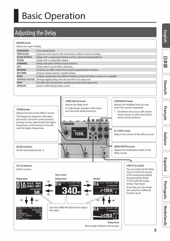
Adjusting the Delay[MODE] knobSelects the type of delay.
STANDARD Clear digital delay.TERA ECHO Spacious echo sound with movement, neither reverb nor delay.SLOW ATTACK Delay with a suppressed attack as if the volume is being faded-in.FILTER Delay with a swept filter added.SHIMMER Delay with pitch-shifted sound mixed in.SFX Delay with a sound-effect character.REVERSE Produces an effect where the sound is played back in reverse.PATTERN Sixteen independently-settable delays.DUAL A delay comprising two different delays connected either in series or in parallel.VINTAGE DIGITAL Vintage digital delay with the warmth of an early unit.TAPE Provides the characteristic wavering sound of the tape echo.ANALOG Gives a mild analog delay sound.
[TONE] knobAdjusts the tone of the effect’s sound.The frequency response is flat when the knob is set to the center position; turning it to the right boosts the higher frequencies, and turning it to the left cuts the higher frequencies.
[TIME/VALUE] knobAdjusts the delay time.To make larger changes in the value, turn the knob while pressing it.
[E. LEVEL] knobAdjusts the volume of the effect sound.
[TAP/CTL] switchYou can easily set the delay time to match the tempo of the song being played by pressing the pedal in time with the song’s tempo (Tap Input).If you like, you can assign this switch to a different function (p. 8).
[I] [H] buttonsSwitch screens.
[H] [I]
[H]
[I]
[H] [I]
Tempo
Delay timeNote length relative to the tempo
[H]
[I]
Delay timeDelay time
Top screen
Turn the [TIME/VALUE] knob to adjust the value.
[MOD DEPTH] knobAdjusts the modulation depth of the delay sound.
[FEEDBACK] knobAdjusts the feedback level (or how much the sound is repeated).
* Oscillation may occur with certain input sounds, or when the knob is set at certain positions.
[A] [B] switchesSwitch banks/patches (p. 7).
6
Basic Operation
Turning Delay On/Off
Patch A delayEach time you press the [A] switch, the delay alternately turns on (lit blue) / off (unlit).
Patch B delayEach time you press the [B] switch, the delay alternately turns on (lit blue) / off (unlit).
Press once
Blue: on Unlit: off
MEMO
You can also make settings so that patches A and B are used simultaneously (p. 19).
Patches and BanksSettings for MODE, FEEDBACK, EFFECT LEVEL, TONE, MOD DEPTH, and TIME are collectively called a “patch.” You can select patches using [A], [B], and [TAP/CTL] switches (p. 19). A combination of patches A, B, and C is called a “bank.”
Bank down
Bank upBANK 02
BANK 99
BANK 01
Patch 01A Patch 01B Patch 01C
* If you want to use the [TAP/CTL] switch to select patch C, refer to “Assigning the Functions of the [A], [B], and [TAP/CTL] Switches” (p. 19).
7
Basic Operation
Switching Banks/Patches
1 Switch banks (01–99).
Bank down (press the [A] and [B] switches simultaneously)
Bank up (press the [B] and [TAP/CTL] switches simultaneously)
2 Press a blinking switch ([A] or [B]) to switch patches.
Blinking blue
MEMO
You can recall a different patch by turning the [TIME/VALUE] knob while you hold down the [EXIT] button.
MEMO
You can use the following functions to switch patches/banks.
5 “Assigning the Functions of the [A], [B], and [TAP/CTL] Switches” (p. 19)
5 “Specifying Whether to Carry-Over the Delay Sound” (p. 19)
8
Basic Operation
Using the [TAP/CTL] Switch to Control the DelayWith the default settings, the [TAP/CTL] switch is used for tap input, but you can change this setting to make the switch affect the delay in various ways.
1 Press the [EDIT] button.
2 Use the [H] [I] buttons to select “CONTROL” and then press the [EDIT] button.
3 Use the [H] [I] buttons to select “TAP/CTL,” and use the [TIME/VALUE] knob to assign a function.
Value Explanation
TAP Use the switch for tap input.
CTL
HOLD Repeats the delay sound while you hold down the switch.WARP Simultaneously controls the delay sound’s feedback level and volume to produce a totally unreal delay.TWIST A new type of delay that produces an aggressive, spinning sensation.MOMENT Outputs the delay sound only while you hold down the switch.ROLL 1/2 Cuts the delay time to 1/2 the setting only while you hold down the switch.ROLL 1/4 Cuts the delay time to 1/4 the setting only while you hold down the switch.ROLL 1/8 Cuts the delay time to 1/8 the setting only while you hold down the switch.FADE IN Fades-in the delay sound.
FADE OUT Fades-out the delay out.
ASSIGN Select this if you’re using the ASSIGN 1–8 setting (p. 15).
4 Press the [EXIT] button to return to the top screen.
9
Basic Operation
Playing Phrase LoopsBy operating the switches, you can carry out recording and playback in real time to create layered performances. You can apply the delay while creating layered performances.
ExitTo exit Phrase Loop, hold down the [TAP/CTL] switch for at least two seconds while stopped.
* The recorded content will be erased when you exit Phrase Loop.
* The recorded content will not be saved.
OverdubRecord additional layers while playing back the loop.[A] and [B] are lit red.
Loop playback[B] is lit red.
RecordRecord the performance. [A] is lit red.
Enter Phrase Loop modeIf you hold down the blue-lit [A] or [B] switch for two seconds or longer, the Phrase Loop enters the standby condition, and [A] blinks red.
Red
StopStop playback.[B] blinks in red.
ClearErase the phrase.[A] blinks in red.
Recording time (seconds)
Frequency 48 kHz 96 kHz
Mono 120 60Stereo 60
10
Editing a PatchYou can edit a variety of patch-related parameters.
1 Press the [EDIT] button.
2 Use the [H] [I] buttons to select “PATCH,” and then press the [EDIT] button.
3 Use the [H] [I] buttons to select a parameter, and use the [TIME/VALUE] knob to edit the value.
4 Press the [EXIT] button to return to the top screen.
* Save the edited patch as described in the procedure on “Saving a Patch” (p. 11).
Basic [EDIT] operationsUse the [H][I] buttons to move the cursorUse the [TIME/VALUE] knob to edit the value
[EDIT] button
Use the [H][I] buttons to move the cursor
[EDIT] button
[EXIT] button
11
Saving a PatchHere’s how to save a patch that you’ve edited.
1 Press the [EXIT] button and [EDIT] button simultaneously.
2 Use the [TIME/VALUE] knob to select the save-destination number.Bank [A] switch [B] switch [TAP/CTL] switch
Bank 01 01A 01B 01CBank 02 02A 02B 02C
: : : :Bank 99 99A 99B 99C
* If you want to use the [TAP/CTL] switch to select patch C, refer to “Assigning the Functions of the [A], [B], and [TAP/CTL] Switches” (p. 19).
3 Press the [H] button to select the patch name.
4 Edit the patch name.[H] [I] buttons Move the cursor[TIME/VALUE] knob Edit the character
5 Press the [EDIT] button to save the patch.If you decide to cancel, press the [EXIT] button.
By moving the cursor to “WRITE TO” and turning the [TIME/VALUE] knob, you can initialize a patch or exchange patches.
12
Parameter List
PATCHParameter Explanation
MODE Selects the type of delay (p. 5). The same function as the [MODE] knob.TIME Specifies the delay time. The same function as the [TIME/VALUE] knob.BPM Specifies the tempo.NOTE Specifies the delay time with the note length relative to BPM.
FEEDBACK Adjusts the feedback level (or how much the sound is repeated). Higher settings will result in more delay repeats. The same function as the [FEEDBACK] knob.
TONE Adjusts the tone of the delay sound. The same function as the [TONE] knob.EFFECT LEVEL Adjusts the volume of the delay sound. The same function as the [E. LEVEL] knob.MOD DEPTH Adjusts the modulation depth of the delay sound. The same function as the [MOD DEPTH] knob.MOD RATE Adjusts the modulation rate of the delay sound.CARRY OVER You can specify whether the effect sound is carried-over when you switch patches or turn the delay off.DIRECT LEVEL Adjusts the volume of the direct sound when the effect is on.EQ SW Turns the EQ on/off.
EQ LO.CUTSets the frequency at which the low cut filter begins to take effect. When “FLAT” is selected, the low cut filter will have no effect.
EQ LO.GAIN Adjusts the low frequency range tone.EQ LM.GAIN Adjusts the low-middle frequency range tone.EQ LM.FREQ Specifies the center of the frequency range that will be adjusted by the LM.GAIN.EQ LM.Q Adjusts the width of the area affected by the EQ centered at the LM.FREQ. Higher values will narrow the area.EQ HM.GAIN Adjusts the high-middle frequency range tone.EQ HM.FREQ Specifies the center of the frequency range that will be adjusted by the HM.GAIN.EQ HM.Q Adjusts the width of the area affected by the EQ centered at the HM.FREQ. Higher values will narrow the area.EQ HI.GAIN Adjusts the high frequency range tone.
EQ HI.CUTSets the frequency at which the high cut filter begins to take effect. When “FLAT” is selected, the high cut filter will have no effect.
EQ LEVEL Adjusts the overall volume level of the equalizer.LO DAMP Adjusts the amount by which the low frequency range is reduced each time the effect sound is repeated.LO DAMP F Specifies the frequency of the low range that is reduced by LO DAMP.HI DAMP Adjusts the amount by which the high frequency range is reduced each time the effect sound is repeated.HI DAMP F Specifies the frequency of the high range that is reduced by HI DAMP.
DUCK SENS Adjusts the sensitivity at which the volume is automatically adjusted according to the input. Higher values allow the adjustment to occur in response to lower volumes.
DUCK PRE DEPTH The volume being “input” to the delay is automatically reduced when the input sound is loud. The amount of reduction increases as this setting approaches 100.
DUCK POST DEPTH The volume being “output” to the delay is automatically reduced when the input sound is loud. The amount of reduction increases as this setting approaches 100.
EFFECT PAN Adjusts the stereo position of the effect sound.DIRECT PAN Adjusts the stereo position of the direct sound.
13
Parameter List
MODE: TERA ECHOParameter Explanation
RESONANCE This adjusts the amount of resonance (and the tone coloration) of the effect sound.
MODE: SLOW ATTACKParameter Explanation
SENS
Adjusts the sensitivity of the slow gear.When it is set to a lower value, the effect of the slow gear can be obtained only with a stronger picking, while no effect is obtained with a weaker picking. When the value is set higher, the effect is obtained even with a weak picking.
RISE TIME Adjusts the time needed for the volume to reach its maximum from the moment you begin picking.
MODE: FILTERParameter Explanation
LFO TYPE Selects the curve at which the filter is moved.LFO RATE Adjusts the rate at which the filter is moved.LFO DEPTH Adjusts the range over which the filter is moved.TYPE Selects the type of filter (LPF/BPF/HPF). CUTOFF Adjusts the frequency at which the filter operates. Higher values raise the frequency.RESONANCE Adjusts the operation of the filter. Higher values produce a stronger tonal character.FILTER POS Specifies whether the filter is placed before or after the delay.
MODE: SHIMMERParameter Explanation
PITCH SHIFT Specifies the amount of pitch shift in semitone units.
PITCH FINE Specifies a fine adjustment to the amount of pitch shift. A change of 100 in the Fine setting corresponds to a change of 1 in the Pitch Shift setting.
PITCH BAL Adjusts the balance between the pitch-shifted sound that is input to the delay and the direct sound.
DIRECT FB Adjusts the amount of feedback for the delay that is applied to the direct sound. This is specified as a proportion (%) relative to the feedback specified by the [FEEDBACK] knob.
MODE: SFXParameter Explanation
BIT DEPTH Specifies the bit depth.SAMPLE RATE Specifies the sampling rate.LoFi BAL Adjusts the volume balance between the direct sound and the effect sound.TR WAVE Adjusts changes in volume level. A higher value will steepen wave’s shape.TR RATE Adjusts the frequency (speed) of the change.TR DEPTH Adjusts the depth of the effect.
MODE: PATTERNParameter Explanation
PATTERNSelects the delay pattern.You can choose from preset patterns PAT1–PAT10 and the USER pattern which you are free to set.
DELAY 1–16 TIME Adjusts the proportion relative to the Delay 1–16 delay time when PATTERN is set to “USER.”DELAY 1–16 LEVEL Adjusts the Delay 1–16 volume when PATTERN is set to “USER.”DELAY 1–16 PAN Adjusts the Delay 1–16 stereo position when PATTERN is set to “USER.”
14
Parameter List
MODE: DUALParameter Explanation
DUAL MODE Specifies whether the two delays are connected in series or in parallel.DUAL TYPE Selects the type of delay.DUAL LINK Link the delay time and feedback of the second delay to the settings of the first delay.D2 TIME Specifies the delay time of the second delay. This is the same as the [TIME/VALUE] knob.
D2 FEEDBACK Adjusts the amount of feedback (repetition) for the second delay. Higher values produce a larger number of delay repeats. This is the same as the [FEEDBACK] knob.
D2 E. LEVEL Adjusts the volume of the second delay sound. This is the same as the [E. LEVEL] knob.
MODE: VINTAGE DIGITALParameter Explanation
TYPE Selects the type of unit that is being modeled.FILTER Turns the high-cut filter on/off when TYPE is set to “SDE-3000.”
TIMEx2 Specifies whether the sampling frequency is halved and the delay time doubled when TYPE is set to “SDE-2000” or “SDE-3000.”
MODE: TAPEParameter Explanation
TYPE Selects the type of unit that is being modeled.
MODE: ANALOGParameter Explanation
STAGE Specifies the number of BBD stages. The delay time lengthens in proportion to the number of stages.
CONTROLParameter Explanation
TAP/CTL Specifies whether the [TAP/CTL] switch is used as TAP or as CTL.CTL FUNC Specifies how the [TAP/CTL] switch operates when pressed if it is being used as CTL.
CTL 1/2 PREF Specifies whether the CTL 1/2 switch has a different setting for each patch or the same setting shared by all patches.
CTL 1/2 FUNC Specifies the operation that occurs when the CTL 1/2 switch is pressed.
CTL 1/2 MODE Specifies whether the setting is on only while the CTL 1/2 switch is held down or whether the setting alternates on/off each time the switch is pressed.
EXP PREF Specifies whether the EXP pedal has a different setting for each patch or the same setting shared by all patches.
EXP FUNC Specifies the operation that occurs when the EXP pedal is pressed.
15
Parameter List
ASSIGN
ASSIGN COMMONParameter Explanation
SENS (INPUT SENS) This adjusts the input sensitivity when INPUT LEVEL is selected for SOURCE.
ASSIGN 1–8Parameter Value Explanation
SW OFF, ON Turns the ASSIGN 1–8 on/off.
SOURCE
Specifies the controller (source).TAP/CTL [TAP/CTL] switch.
EXP PDL(EXP PEDAL)
External footswitch (EV-5 etc.; available separately) connected to the CTL 1,2/EXP jack.
CTL1, 2 PDL External footswitch connected to the CTL 1,2/EXP jack.
INT PDL
Internal pedalThe virtual expression pedal will begin operating when started by the specified trigger (TRIGGER), modifying the parameter specified by “TARGET.”For details on the parameters that can be assigned to the internal pedal, refer to “TIME” and “CURVE” (p. 16)
WAVE PDL
Wave pedalThe virtual expression pedal will cyclically modify the parameter specified by “TARGET” in a fixed wave form.
INPUT
(INPUT LEVEL)
The assigned target parameter will change according to the input level.
* If you want to adjust the input sensitivity, set the SENS (INPUT SENS).CC#1–31, CC#64–95 Controller number from an external MIDI device
MODE (SOURCE MODE)
Specifies the operation of the controller.
MOMENTThe value will normally be OFF (minimum value), and will be ON (maximum value) only while the control is being operated.
* If you want to use the internal pedal or wave pedal, set to “MOMENT.”
TOGGLE The value will toggle between OFF (minimum) and ON (maximum) each time the control is operated.
TRG This selects the parameter to be changed.
MIN (TARGET MIN)MAX (TARGET MAX)
Specifies the range of change for the parameter. The values will depend on the parameter that’s assigned by “TARGET.”
ACT.LO(ACT RANGE LO)
Within the operating range of the source, this specifies the range that will control the target parameter.The target parameter will be controlled within the range specified. Normally, you should leave ACT.LO at “0” and ACT.HI at “127.”
ACT.HI(ACT RANGE HI)
WAV.RT(WAVE RATE)*1
0–100,
BPM –Specifies the time for one cycle of the wave pedal.
* If, due to the tempo, the time is longer than the range of allowable settings, it is then synchronized to a period either 1/2 or 1/4 of that time.
16
Parameter List
Parameter Value Explanation
WAV.FM(WAVE FORM)*1
SAW, TRI, SIN
Select one of the following to specify the change produced by the wave pedal.
SAW TRI SIN
TRIGGER(INT PEDAL TRIGGER)*2
Specifies how the motion of the internal pedal will be triggered.
PAT CNG(PATCH CHANGE)
This is activated when a patch is selected.
EXP LOThis is activated when an external expression pedal connected to the CTL 1,2/EXP jack is set to the minimum position.
EXP MIDThis is activated when the external expression pedal connected to the CTL 1,2/EXP jack is moved through the middle position.
EXP HIThis is activated when the external expression pedal connected to the CTL 1,2/EXP jack is set to the maximum position.
CTL1, 2 PDLThis is activated when an external footswitch connected to the CTL 1,2/EXP jack is operated.
CC#1–#31CC#64–#95
This is activated when a control change is received.
TIME(INT PEDAL TIME)*2
0–100This specifies the time over which the internal pedal will move from the toe-raised position to the toe-down position.
CURVE(INT PEDAL CURVE)*2
LINEAR, SLOW (SLOW RISE), FAST (FAST RISE)
Select one of the following curves to specify the change produced by the internal pedal.
LINEAR SLOW FAST
*1 SOURCE=INT PDL only*2 SOURCE=WAVE PDL only
17
Parameter List
SYSTEMParameter Explanation
CONTRAST Adjusting the contrast of the displayOUTPUT Selects how output occurs.BANK MODE Specifies the timing at which the patch is changed when you change banks.BANK EXTENT MIN Sets the lower limit for the banks.BANK EXTENT MAX Sets the upper limit for the banks.KNOB LOCK Specifies whether knob operations will be disabled.KNOB MODE Specifies how knob operations occur.BYPASS Specifies how the bypass sound is output.
PEDAL ACT Specifies whether the operation occurs when you press the [A], [B], or [TAP/CTL] switch or when you release the switch.
FSW HOLD TIME Specifies the number of seconds of holding down the [A], [B], or [TAP/CTL] switch that is interpreted as a long-press.
FSW MODE Specifies how the footswitch is used (p. 19).USB MODE Specifies the USB operating mode (p. 21).LOOP MODE Specifies the sampling frequency.
MIDIParameter Explanation
Rx CHANNEL Specifies the receive channel.Tx CHANNEL Specifies the transmit channel.PC IN Specifies whether program changes are received.PC OUT Specifies whether program changes are transmitted.CC IN Specifies whether control changes are received.CC OUT Specifies whether control changes are transmitted.TIME CONTROL Specifies whether operations of the [TIME/VALUE] knob are transmitted and received.A SW CC [A] switch
Specifies the controller number of the corresponding knobs or switches.
B SW CC [B] switchTAP/CTL SW CC [TAP/CTL] switchFEEDBACK CC [FEEDBACK] knobE. LEVEL CC [E. LEVEL] knobTONE CC [TONE] knobMOD DEPTH CC [MOD DEPTH] knobCTL1 CC External CTL1 switchCTL2 CC External CTL2 switchEXP CC External EXP pedalEFFECT ON/OFF CC Specifies the controller number that switches between delay-on and bypass.LOOP ON/OFF CC Specifies the controller number that switches the phrase loop function on/off.
LOOP REC/DUB CC Specifies the controller number that executes recording or overdubbing when using the phrase loop function.
LOOP PLAY CC Specifies the controller number that executes loop playback when using the phrase loop function.LOOP STOP CC Specifies the controller number that stops playback when using the phrase loop function.LOOP CLEAR CC Specifies the controller number that clears the phrase when using the phrase loop function.SYNC Selects the tempo clock input that is used for synchronization.
REALTIME SRC Selects the source of the realtime messages that are transmitted from the MIDI OUT connector or the USB port.
MIDI IN->OUT Specifies the connector to which MIDI messages received from the MIDI IN connector are output.USB IN->OUT Specifies the connector to which MIDI messages received from the USB port are output.DEVICE ID Sets the MIDI Device ID used for transmitting and receiving System Exclusive messages.
18
Parameter List
MIDI PC MAPParameter Explanation
BNK-PC# Specifies the program number that corresponds to each patch number.
19
Convenient Functions
Specifying Whether to Carry-Over the Delay SoundYou can specify whether the effect sound is carried-over (ON/OFF) when you switch patches or turn the delay off.
1 Press the [EDIT] button.
2 Use the [H] [I] buttons to select “PATCH,” and then press the [EDIT] button.
3 Use the [H] [I] buttons to select “CARRY OVER,” and use the [TIME/VALUE] knob to select ON / OFF.
4 Press the [EXIT] button to return to the top screen.
Assigning the Functions of the [A], [B], and [TAP/CTL] Switches
1 Press the [EDIT] button.
2 Use the [H] [I] buttons to select “SYSTEM” and then press the [EDIT] button.
3 Use the [H] [I] buttons to select “FSW MODE,” and use the [TIME/VALUE] knob to select the mode.Mode Explanation
NORMAL
Use the [A] and [B] switches to select patch A or patch B, and use the [TAP/CTL] switch for tap input.
* If you want to use the [TAP/CTL] switch as the CTL, set the “TAP/CTL FUNC” to “CTL” (p. 8).
A/B/CUse the [TAP/CTL] switch to select patch C.
* In this case, you can't use the [TAP/CTL] switch for the TAP or CTL functions.
A/B SIMUL Patches A and B can be used simultaneously. Press the unlit [A] or [B] switch to make both light.
SW DN/UP Use the [A] switch to turn delay on/off, and use the [B] switch and [TAP/CTL] switch to change patches.
4 Press the [EXIT] button to return to the top screen.
20
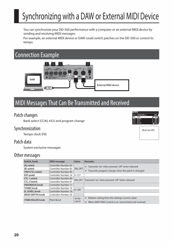
Synchronizing with a DAW or External MIDI DeviceYou can synchronize your DD-500 performance with a computer or an external MIDI device by sending and receiving MIDI messages.For example, an external MIDI device or DAW could switch patches on the DD-500 or control its tempo.
Connection Example
External MIDI device
DAW
MIDI Messages That Can Be Transmitted and Received
Patch changesBank select (CC#0, #32) and program change
SynchronizationTempo clock (F8)
Patch dataSystem exclusive messages
Other messagesSwitch, knob MIDI message Value Remarks
[A] switch Controller Number 82ON, OFF
5 Transmits “on” when pressed, “off” when released
5 Transmits program change when the patch is changed[B] switch Controller Number 83[TAP/CTL] switch Controller Number 84EXP pedal Controller Number 16 0–127CTL 1 switch Controller Number 80
ON, OFF Transmits “on” when pressed, “off” when releasedCTL 2 Switch Controller Number 81[FEEDBACK] knob Controller Number 17
0–100[TONE] knob Controller Number 19[E. LEVEL] knob Controller Number 18[MOD DEPTH] knob Controller Number 20
[TIME/VALUE] knob Pitch Bend -8192–+8191
5 Relative setting from the setting’s current value
5 When MIDI TIME Control is on: transmitted and received
Must be ON
21
Synchronizing with a DAW or External MIDI Device
MIDI Messages That Can Only Be ReceivedStatus MIDI message Value Remarks
Delay on, Bypass Controller Number 21
ON, OFF
ON = Delay on, OFF = BypassPhrase loop Controller Number 22
Phrase Loop functionRecord, Overdub Controller Number 23Loop playback Controller Number 24Stop Controller Number 25Clear Controller Number 26
MIDI RoutingFor details on how to set the MIDI parameters, refer to “Basic [EDIT] operations” (p. 10).
Main Setting ItemsItem Parameter Explanation
Synchronization source SYNC
Specifies whether the synchronization source is the DD-500 (INTERNAL), USB, or an external device connected via MIDI.
Realtime messages REALTIME SRCSpecifies whether realtime messages generated by the DD-500 are transmitted, and whether realtime messages received via the MIDI IN connector or the USB port are transmitted.
MIDI message output destination
MIDI IN->OUT Specifies the MIDI messages that are transmitted from the MIDI OUT connector.
USB IN->OUT Specifies the MIDI messages that are transmitted from the USB port.
If you experience problems connecting with your DAWNormally, you don’t need to install a driver in order to connect the DD-500 to your computer. However, if some problem occurs, or if the performance is poor, using the BOSS original driver may solve the problem.In this case, setting “USB MODE” to “VENDER” on the DD-500, install the driver on your personal computer.For details on downloading and installing the BOSS original driver, refer to the BOSS website. For further details, refer to the Readme.htm file that comes with the download.& http://www boss info/support/The program you need to use, and the steps you need to take to install the USB driver will differ depending on your computer setup, so please carefully read and refer to the Readme.htm file that comes with the download.
22
Assigning a Function to an External PedalYou can assign a function to a footswitch (sold separately: FS-5U, FS-5L, FS-6, FS-7) or expression pedal (sold separately: Roland EV-5 etc.) connected to the CTL 1,2/EXP jack.
1 Press the [EDIT] button.
2 Use the [H] [I] buttons to select “CONTROL,” and then press the [EDIT] button.
3 Use the [H] [I] buttons to select a parameter, and use the [TIME/VALUE] knob to edit the value.
Parameter Value Explanation
PREFPATCH Different settings can be made for each patch.
SYSTEM The same settings are shared by all patches.FUNC Specify the function of the footswitches connected to the CTL 1,2/EXP jack.
MODEMOMENT The switch is normally off (minimum value), and turns on
(maximum value) only while you hold it down.
TOGGLE The switch alternately switches off (minimum value) and on (maximum value) each time you press it.
CTL1 FUNC and CTL2 FUNC SettingsValue Explanation
OFF No function is assigned Select this if you’re using the ASSIGN 1–8 setting (p. 15).TAP Use the switch for tap input.HOLD Repeats the delay sound while you hold down the switch.
WARP Simultaneously controls the delay sound’s feedback level and volume to produce a totally unreal delay.
TWIST A new type of delay that produces an aggressive, spinning sensation.MOMENTARY Outputs the delay sound only while you hold down the switch.ROLL 1/2 Cuts the delay time to 1/2 the setting only while you hold down the switch.ROLL 1/4 Cuts the delay time to 1/4 the setting only while you hold down the switch.ROLL 1/8 Cuts the delay time to 1/8 the setting only while you hold down the switch.FADE IN
Fades-in/-out the delay sound.FADE OUTEFFECT SW Turns the effect on/off.BANK UP
Change banks.BANK DOWNLOOPonOff Enter/Exit the Phrase Loop Mode.LOOP CLEAR Erase the phrase.
23
Assigning a Function to an External Pedal
EXP FUNC SettingsValue Explanation
OFF No function is assigned Select this if you’re using the ASGN1–8 setting (p. 15).TIME Controls the DELAY TIME. FEEDBACK Controls the FEEDBACK.TONE Controls the TONE.E. LEVEL Controls the E. LEVEL.MOD DEPTH Controls the MOD DEPTH.MOD RATE Controls the MOD RATE.
4 Press the [EXIT] button to return to the top screen.
24
Restoring the Factory Default SettingsHere’s how to reset the settings to their factory state. If you like, you can also reset just the system settings or just a specific range of patches.
1 Press the [EDIT] button.
2 Use the [H] [I] buttons to select “FACTORY RESET,” and then press the [EDIT] button.
3 Use “FROM” and “TO” to specify the range that you want to reset.Parameter Value Explanation
FROMTO
SYSTEM System parameter settings.01A–99C Settings for Patches.
4 Press the [EDIT] button.A confirmation message appears.
5 Press the [EDIT] button to reset the settings.If you decide to cancel without resetting, press the [EXIT] button.
Transmitting Data to an External MIDI DeviceYou can use Exclusive messages to set another DD-500 to the same settings or to save effect sound settings to MIDI sequencers and other such devices. This transmission of data is referred to as bulk dump.
1 Press the [EDIT] button.
2 Use the [H] [I] buttons to select “MIDI BULK DUMP,” and then press the [EDIT] button.
3 Use “FROM” and “TO” to specify the range that you want to reset.Parameter Value Explanation
FROMTO
SYSTEM System parameter settings.01A–99C Settings for Patches.TEMP Current settings in the panel display.
4 Press the [EDIT] button.The bulk dump is executed.
25
TroubleshootingProblem Items to check Action
Power does not turn on
Is your guitar correctly connected to the INPUT A/MONO jack? Check the connection once again.
Could the batteries be low? Install fresh batteries.Is the specified PSA series AC adaptor connected correctly? Check the connection once again.
No sound is output / No delay sound is output / No direct sound is output
Is the SYSTEM: OUTPUT (p. 17) setting correct? Check the SYSTEM: OUTPUT (p. 17) setting
and the OUTPUT jacks connection.Is your output device correctly connected to the OUTPUT jacks?
Footswitch does not change sounds as you expect
Is the SYSTEM: FSW MODE (p. 19) setting correct?
The FSW MODE (p. 19) setting determines what happens when you press the [A], [B], and [TAP/CTL] switches. Check the setting.
Delay sound does not remain when you switch patches or turn off the delay
Is the PATCH: CARRY OVER (p. 19) setting “ON”?
If CARRY OVER (p. 19) is set to “OFF” the delay sound does not remain.
Could the SYSTEM: BYPASS (p. 17) setting be “TRUE”?
If this is set to “TRUE” (True bypass), the delay sound cannot be carried-over when the effect is turned off even if CARRY OVER is turned “ON.” Set SYSTEM: BYPASS to “BUFFERED.”
Main SpecificationsBOSS DD-500: DIGITAL DELAY
Power SupplyAlkaline battery (AA, LR6) x 4AC adaptor
Current Draw 200 mA
Dimensions170 (W) x 138 (D) x 62 (H) mm6-3/4 (W) x 5-7/16 (D) x 2-1/2 (H) inches
Weight (including batteries)1.0 kg2 lbs 4 oz
Accessories Owner’s manual, Leaflet “USING THE UNIT SAFELY”, Alkaline Batteries (AA LR6) x 4
Options (sold separately)
AC adaptor: PSA seriesFootswitch: BOSS FS-5U, FS-5LDual Footswitch: BOSS FS-6, FS-7Expression pedal: BOSS FV-500H, FV-500L, Roland EV-5
* 0 dBu = 0.775 Vrms* In the interest of product improvement, the specifications and/or appearance of this unit are subject to change without prior notice.
26
USING THE UNIT SAFELYTo completely turn off power to the unit, pull out the plug from the outletEven with the power switch turned off, this unit is not completely separated from its main source of power. When the power needs to be completely turned off, turn off the power switch on the unit, then pull out the plug from the outlet. For this reason, the outlet into which you choose to connect the power cord’s plug should be one that is within easy reach and readily accessible.
Keep small items out of the reach of childrenTo prevent accidental ingestion of the parts listed below, always keep them out of the reach of small children.
• Included Parts
Rubber feet (p. 2)
IMPORTANT NOTESPower Supply: Use of Batteries
• If operating this unit on batteries, please use alkaline batteries.
Repairs and Data• Before sending the unit away for repairs, be sure to make a backup of the data stored
within it; or you may prefer to write down the needed information. Although we will do our utmost to preserve the data stored in your unit when we carry out repairs, in some cases, such as when the memory section is physically damaged, restoration of the stored content may be impossible. Roland assumes no liability concerning the restoration of any stored content that has been lost.
Additional Precautions• Any data stored within the unit can be lost as the result of equipment failure,
incorrect operation, etc. To protect yourself against the irretrievable loss of data, try to make a habit of creating regular backups of the data you’ve stored in the unit.
• Roland assumes no liability concerning the restoration of any stored content that has been lost.
• The explanations in this manual include illustrations that depict what should typically be shown by the display. Note, however, that your unit may incorporate a newer, enhanced version of the system (e.g., includes newer sounds), so what you actually see in the display may not always match what appears in the manual.
• Never strike or apply strong pressure to the display.
• Use only the specified expression pedal (Roland EV-5, BOSS FV-500L, BOSS FV-500H; sold separately). By connecting any other expression pedals, you risk causing malfunction and/or damage to the unit.
• Do not use connection cables that contain a built-in resistor.
Intellectual Property Right• It is forbidden by law to make an audio recording, video recording, copy or revision
of a third party's copyrighted work (musical work, video work, broadcast, live performance, or other work), whether in whole or in part, and distribute, sell, lease, perform, or broadcast it without the permission of the copyright owner.
• Do not use this product for purposes that could infringe on a copyright held by a third party. We assume no responsibility whatsoever with regard to any infringements of third-party copyrights arising through your use of this product.
• MMP (Moore Microprocessor Portfolio) refers to a patent portfolio concerned with microprocessor architecture, which was developed by Technology Properties Limited (TPL). Roland has licensed this technology from the TPL Group.
• This product contains eParts integrated software platform of eSOL Co.,Ltd. eParts is a trademark of eSOL Co., Ltd. in Japan.
• Roland and BOSS are either registered trademarks or trademarks of Roland Corporation in the United States and/or other countries.
• Company names and product names appearing in this document are registered trademarks or trademarks of their respective owners.