16
owners manual MODELS #6507, #6508, #6509

owners manual
MODELS #6507, #6508, #6509
2 • TQi RADIO SYSTEM
Important Radio System Precautions• Formaximumrange,alwayspointthefrontoftransmitter
towardthemodel.• Donotkinkthereceiver’santennawire.Kinksintheantenna
wirewillreducerange.• DONOTCUTanypartofthereceiver’santennawire.Cuttingthe
antennawillreducerange.• Extendtheantennawireinthemodelasfaraspossiblefor
maximumrange.Itisnotnecessarytoextendtheantennawireoutofthebody,butwrappingorcoilingtheantennawireshouldbeavoided.
• Donotallowtheantennawiretoextendoutsidethebodywithouttheprotectionofanantennatube,ortheantennawiremaygetcutordamaged,reducingrange.Itisrecommendedtokeepthewireinsidethebody(intheantennatube)topreventthechanceofdamage.
Warranty InformationTraxxaswarrantsyourTraxxaselectroniccomponentstobefreefromdefectsinmaterialsorworkmanshipforaperiodofthirty(30)daysfromthedateofpurchase.Beforereturninganyproductforwarrantyservice,pleasecontactourservicedepartmentat1-888-TRAXXAS (U.S. residents only)todiscusstheproblemyouarehavingwiththeproduct.AftercontactingTraxxas,sendthedefectiveunitalongwithyourproofofpurchaseindicatingthedatepurchased,yourreturnaddress,e-mail,adaytimephonenumber,andabriefdescriptionoftheproblemto:
Traxxas, 1100 Klein Road, Plano, TX 75074 Phone: 972-265-8000 Internet: Traxxas.com E-mail: [email protected]
Detailed Limitations for Electronic Components:• Allowingwater,moisture,orotherforeignmaterialtoenterthecomponentorgetontothePCboard.• Exceedingthemaximuminputvoltageoftheelectroniccomponent.• Reversevoltageapplication.• Incorrectinstallationorwiring.
• Componentswornfromuse.• Splicestotheinputorswitchharnesses.• Disassemblingthecase.• Excessiveforcewhenadjusting,pressing,orturninganyofthecontrols.• Tamperingwiththeinternalelectronics.• IncorrectwiringofanFETservo.• Allowingexposedwiringtoshortcircuit.• Anydamagecausedbycrash,flooding,oractofGod.
LimitationsAnyandallwarrantycoveragedoesnotcoverreplacementofpartsandcomponentsdamagedbyabuse,neglect,improperorunreasonableuse,crashdamage,waterorexcessivemoisture,chemicaldamage,improperorinfrequentmaintenance,accident,unauthorizedalterationormodification,oritemsthatareconsideredconsumable.Traxxaswillnotpayforthecostofshippingortransportationofadefectivecomponentfromyoutous.
Limitations of LiabilityTraxxasmakesnootherwarrantiesexpressedorimplied.Traxxasshallnotbeliableforanyspecial,indirect,incidental,orconsequentialdamagesarisingoutoftheassembly,installation,oruseoftheirproductsoranyaccessoryorchemicalrequiredtousetheirproducts.Bytheactofoperating/usingtheproduct,theuseracceptsallresultingliability.InnocaseshallTraxxas’liabilityexceedtheactualpurchasepricepaidfortheproduct.Traxxasreservestherighttomodifywarrantyprovisionswithoutnotice.AllwarrantyclaimswillbehandleddirectlybyTraxxas.TheTraxxaswarrantygivesthecustomerspecificlegalrightsandpossiblyotherrightsthatvaryfromstatetostate.ThecustomerisrequiredtofilloutandreturntheRegistrationCardenclosedwiththeproductasaconditionofthecoverageandperformanceofthewarranty.AlldollaramountsstatedareinUnitedStatesdollars.Theterm“lifetime”shallrefertotheproduct’sproductionlifeatTraxxas.Traxxasisnotobligatedtoprovideupgradedproductsatareducedratewhenapreviousproduct’sproductioncyclehasended.
Traxxas Extended Lifetime Electronics Warranty:Aftertheexpirationdateofthefreewarrantyperiod,Traxxaswillrepairelectroniccomponentsforaflatrate.Theelectronicproductscoveredbythisextendedserviceplanincludeelectronicspeedcontrols,transmitters,receivers,servos,andbatterychargers.Motors,batteries,andmechanicalspeedcontrolsarenotcovered.Thecoveredrepairsarelimitedtonon-mechanicalcomponentsthathaveNOTbeensubjectedtoabuse,misuse,orneglect.Productsdamagedbyintentionalabuse,misuse,modification,orneglect,maybesubjecttoadditionalcharges.VisitTraxxas.comorcall1-888-TRAXXAS(1-888-872-9927)fordetailsonextendedwarrantyserviceandrates.
FCC ComplianceThis device complies with the limits for a Class B digital device as described in part 15 of the FCC rules. Operation is subject to the following two conditions: (1) This device may not cause harmful interference, and (2) this device must accept any interference received, including interference that may cause undesired operation.
The limits for a Class B digital device are designed to provide reasonable protection against harmful interference in residential settings. This product generates, uses and can radiate radio frequency energy, and, if not operated in accordance with the instructions, may cause harmful interference to radio communications.
The user is cautioned that changes or modifications not expressly approved by the party responsible for compliance could void the user’s authority to operate the equipment.
WARRANTY AND PRECAUTIONS
Entire contents ©2012 Traxxas. Other brand names and marks are the property of their respective holders and are used only for purposes of identification. No part of this manual may be reproduced or distributed in print or electronic media without the express written permission of Traxxas. Specifications are subject to change without notice.
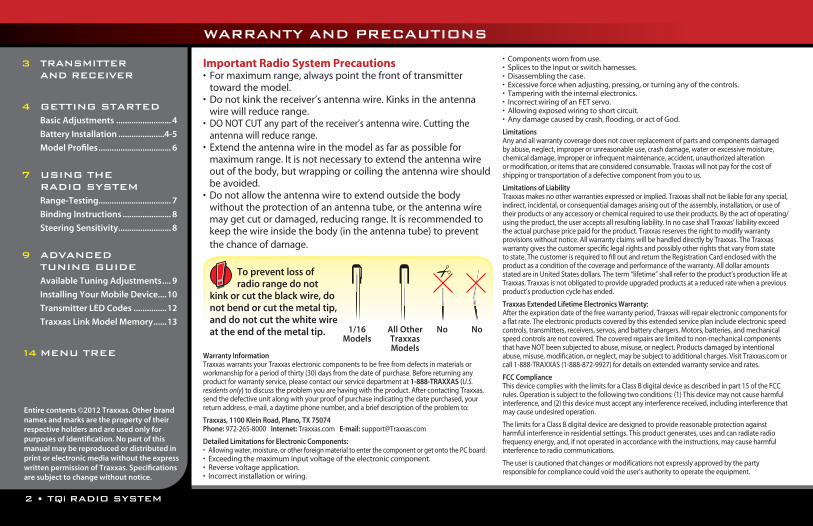
To prevent loss of radio range do not
kink or cut the black wire, do not bend or cut the metal tip, and do not cut the white wire at the end of the metal tip. 1/16
ModelsAll Other Traxxas Models
No No
3 TRANSMITTER AND RECEIVER
4 GETTING STARTED Basic Adjustments ......................... 4
Battery Installation .....................4-5
Model Profiles ................................. 6
7 USING THE RADIO SYSTEM Range-Testing................................. 7
Binding Instructions ...................... 8
Steering Sensitivity ........................ 8
9 ADVANCED TUNING GUIDE Available Tuning Adjustments .... 9
Installing Your Mobile Device....10
Transmitter LED Codes ...............12
Traxxas Link Model Memory ......13
14 MENU TREE

TQi RADIO SYSTEM • 3
TRANSMITTER AND RECEIVER
Steering Trim
Steering Trim
Multi-Function KnobMulti-Function
Knob
Throttle TriggerThrottle Trigger
Throttle Neutral Adjust
Throttle Neutral Adjust
Steering Wheel
Steering Wheel
Receiver
Power Switch
Power Switch
Battery CompartmentBattery Compartment
Docking Base
Standard Base
Set ButtonSet Button
Menu ButtonMenu Button
Red/Green Status LED
Red/Green Status LED
Link Button
LED
Sensor Expansion Port
Models 6507 & 6508 only
Models 6508 & 6509
Model 6507
Shift Switch(Channel 3)
T-Lock Switch (Channel 4)Models 6507 & 6508 only
#6507 - 4-channel with Docking Base; #6508 - 4-channel; #6509 - 2-channel

4 • TQi RADIO SYSTEM
Installing Transmitter Batteries in the Standard BaseYourTQitransmitteruses4AAbatteries.Thebatterycompartmentislocatedinthebaseofthetransmitter.
1.Removethebatterycompartmentdoorbypressingthetabandslidingthedooropen.
2.Installthebatteriesinthecorrectorientationasindicatedinthebatterycompartment.
3.Reinstallthebatterydoorandsnapitclosed.
4.Turnonthetransmitterandcheckthestatusindicatorforasolidgreenlight.
IfthestatusLEDflashesred,thetransmitterbatteriesmaybeweak,dischargedorpossiblyinstalledincorrectly.Replacewithneworfreshlychargedbatteries.Thepowerindicatorlightdoesnotindicatethechargelevelofthebatterypackinstalledinthemodel.RefertotheTroubleshootingsectiononpage12formoreinformationonthetransmitterStatusLEDcodes.
TQi Radio System Basic AdjustmentsSteering Trim Theelectronicsteeringtrimlocatedonthefaceofthetransmitteradjuststheneutral(center)pointofthesteeringchannel.
Multi-Function KnobTheMulti-Functionknobcanbeprogrammedtocontrolavarietyoffunctions.Fromthefactory,theMulti-Functionknobcontrolssteeringsensitivity,
alsoknownasexponentialor“expo.”Whentheknobisturnedcounterclockwiseallthewaytotheleft(defaultposition),expoisoffandsteeringsensitivitywillbelinear(themostcommonlyusedsetting).Turningtheknobclockwisewill“addexpo”anddecreasethesteeringsensitivityintheinitialrangeofsteeringwheeltravelleftorrightfromcenter.Formoredetailonsteeringexponential,refertopage8.
Throttle Neutral Adjustment Thethrottleneutraladjustmentislocatedonthetransmitterfaceandcontrolstheforward/reversetravelofthethrottletrigger.Changetheadjustmentbypressingthebuttonandslidingittothedesiredposition.Therearetwosettingsavailable:
50/50:Allowsequaltravelforbothaccelerationandreverse.70/30:Allowsmorethrottletravel(70%)andlessreversetravel(30%).
We strongly recommend to leave this control in its factory location until you become familiar with all the adjustments and capabilities of your model.
Note: 50/50isthedefaultfactorysettingandtherequiredsettingforTraxxasnitromodels.Tochangethethrottleneutraladjustpositionforanelectricmodel,turnthetransmitteroffbeforeadjustingtheneutralposition.You will need to reprogram your electronic speed control to recognize the 70/30 setting.Seeyourspeedcontrol’sinstructions.
GETTING STARTED

TQi RADIO SYSTEM • 5
Installing Batteries in the TQi Docking Base (Model #6507 Only)YourTQitransmitteruses4AAbatteries.Thebatterycompartmentislocatedinthebaseofthetransmitter.
1.Removethebatterycompartmentdoorbypressingthetabandslidingthedooropen.
2.Removethebatteryholder.Installthebatteriesinthebatteryholder.Correctorientationisindicatedinthebatteryholder.Makesurethebatteryholderispluggedintothetransmitter.
3.Reinstallthebatterydoorandsnapitclosed.
4.Turnonthetransmitterandcheckthe“ON”LEDforasolidgreenlight.Note:SwitchingthetransmitteronwithyourmobiledeviceinstalledwillautomaticallylaunchtheTraxxasLinkapplication.
IfthestatusLEDflashesred,thetransmitterbatteriesmaybeweak,dischargedorpossiblyinstalledincorrectly.Replacewithneworfreshlychargedbatteries.Thepowerindicatorlightdoesnotindicatethechargelevelofthebatterypackinstalledinthemodel.IftheTraxxasLinkapplicationisinstalledandrunning,thereisabatterylevelicon(see image below)onthemainmenubarthatwillgiveyouanindicationofthechargelevelofthetransmitterbatteries.
Note:TheDockingBasewillchargeyourmobiledeviceaslongasthetransmitteristurnedon.
ThisfeaturemaybeswitchedoffbyaccessingthePreferencesscreenintheTraxxasLinkapplication.
TQi Docking Base Battery Charging JackTheDockingBaseincorporatesastandardchargingjackforusewithoptionalTraxxasrechargeableNiMHbatterypack(#3037)andwallcharger(#6545)(each sold separately).Note:ThechargerandchargingjackwillnotchargerechargeableAAbatteriesinstalledinthestandard4-cellAAbatteryholdersuppliedwiththeTQi.Only use the charger and charging jack with the #3037 Traxxas NiMH battery.
Optional #3037 Traxxas NiMH battery installation
Use the Right BatteriesYour transmitter uses AA batteries. Use new alkaline batteries.
Do not use rechargeable AA cells to power the TQi transmitter, as they will not provide sufficient voltage for optimum transmitter performance.
The #3037 Traxxas 5-cell rechargeable battery pack can be used in place of 4 AA alkaline cells. The #3037 battery has the same voltage (6 volts) as four alkaline cells.
Caution: Discontinue running your model at the first sign of weak batteries (flashing red light on the transmitter) to avoid losing control.
GETTING STARTED
6 • TQi RADIO SYSTEM
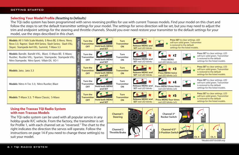
Models:All1/16thScaleModels;E-RevoBE;E-Revo;Revo;Revo3.3;Raptor;Slash4X4Series;SlashSeries;SlashVXL;Slayer;Stampede4x4VXL;Summit;T-Maxx3.3 P
rofi
le 1 Turn the
Transmitter OFF
Hold both MENU
and SET
Turn Transmitter
ON
Release MENU and SET redLEDblinks
Press SET toclearsettings.LEDwillturnsolidgreen.Transmitterisrestoredtothedefaultsettingsforthelistedmodels.
Models:Bandit;BanditVXL;Blast;E-MaxxBE;E-Maxx;Rustler;RustlerVXL;Spartan;Stampede;StampedeVXL;NitroStampede;NitroSport;VillainEX;XO-1 P
rofi
le 2 Turn the
Transmitter OFF
Hold both MENU
and SET
Turn Transmitter
ON
Release MENU and SET redLEDblinks
x 2
Press MENU redLEDblinks(x2)
Press SET toclearsettings.LEDwillturnsolidgreen.Transmitterisrestoredtothedefaultsettingsforthelistedmodels.
Models:Jato;Jato3.3
Pro
file
3 Turn the Transmitter
OFF
Hold both MENU and SET
Turn Transmitter
ON
Release MENU and SET redLEDblinks
x 3
Press MENU twiceredLEDblinks(x3)
Press SET toclearsettings.LEDwillturnsolidgreen.Transmitterisrestoredtothedefaultsettingsforthelistedmodels.
Models:Nitro4-Tec3.3;NitroRustler;Blast
Pro
file
4 Turn the Transmitter
OFF
Hold both MENU and SET
Turn Transmitter
ON
Release MENU and SET redLEDblinks
x 4
Press MENU three timesredLEDblinks(x4)
Press SET toclearsettings.LEDwillturnsolidgreen.Transmitterisrestoredtothedefaultsettingsforthelistedmodels.
Models:T-Maxx3.3;T-MaxxClassic;S-Maxx
Pro
file
5 Turn the Transmitter
OFF
Hold both MENU and SET
Turn Transmitter
ON
Release MENU and SET redLEDblinks
x 5
Press MENU four timesredLEDblinks(x5)
Press SET toclearsettings.LEDwillturnsolidgreen.Transmitterisrestoredtothedefaultsettingsforthelistedmodels.
Selecting Your Model Profile (Resetting to Defaults)TheTQiradiosystemhasbeenprogrammedwithservoreversingprofilesforusewithcurrentTraxxasmodels.Findyourmodelonthischartandfollowthestepstosetthedefaulttransmittersettingsforyourmodel.Thesettingsforservodirectionwillbeset,butyoumayneedtoadjustthetrimandendpointsettingsforthesteeringandthrottlechannels.Shouldyoueverneedrestoreyourtransmittertothedefaultsettingsforyourmodel,usethestepsdescribedinthischart.
Using the Traxxas TQi Radio System with non-Traxxas Models
GETTING STARTED
TheTQiradiosystemcanbeusedwithallpopularservosinanyhobby-gradeR/Cvehicle.Fromthefactory,thetransmitterissetforProfile1,witheachchannelsetas“reversed.”Thecharttotherightindicatesthedirectiontheservoswilloperate.Followtheinstructionsonpage14ifyouneedtochangethesesetting(s)tosuityourmodel.
*Models 6507 & 6508 only
Channel 1Steering
Channel 3*Rocker Switch
Channel 2Throttle/Brake
Channel 4/5*3-Position Switch
Ch. 4 Ch. 5
TQi RADIO SYSTEM • 7
BeforeinstallingtheTQiradiosysteminyourmodel,makecertainthesteeringtrimknobiscentered.Afteryouhaveinstalledandboundtheradiosystem,confirmthesteeringservoandthrottleservo(ifinstalled)operateproperly:turningthesteeringwheelrightmakesthefrontwheelsturnright(andvice-versa),andpullingthetriggertothegripopensthethrottleofyournitroengine.Ifeithercontroloperates“backwards,”followthemenutreeonpage14orusetheTraxxasLinkapplication(#6507TQiwithDockingBaseonly),toreversetheservo’soperation.
Afterconfirmingcorrectservooperation,usetheTQi’ssteeringtrimknobtocenteryourmodel’sfrontwheelssoitdrivesstraightwiththesteeringwheelatitsneutralposition.Ifthereisnotenoughadjustmenttoachievethiswiththesteeringtrimknob,resetthesteeringtrimtoitscenterposition,thenremoveandreinstalltheservo’ssteeringhorntocenterthesteeringsystemascloseaspossible.Thesteeringtrimknobcannowbeusedtomakethefinaladjustments.
Repeatthisprocessforthethrottleservo.Toaccessthrottletrim,followthestepsinthemenutreeonpage14.
Ifyourmodelisequippedwithanelectronicspeedcontrol,itwillhavetobecalibratedtotheTQiradiosystem.Followtheinstructionsincludedwithyourvehicleoryourspeedcontroltocalibrateitproperly.
Range-Testing the Radio SystemBeforeeachrunningsessionwithyourmodel,youshouldrange-testyourradiosystemtoensurethatitoperatesproperly.
1.Turnontheradiosystemandcheckitsoperationasdescribedintheprevioussection.
2.Haveafriendholdthemodel.Makesurehandsandclothingareclearofthewheelsandothermovingpartsonthemodel.
3.Walkawayfromthemodelwiththetransmitteruntilyoureachthefarthestdistanceyouplantooperatethemodel.
4.Operatethecontrolsonthetransmitteronceagaintobesurethatthemodelrespondscorrectly.
5.Donotattempttooperatethemodelifthereisanyproblemwiththeradiosystemoranyexternalinterferencewithyourradiosignalatyourlocation.
Higher Speeds Require Greater DistanceThefasteryoudriveyourmodel,themorequicklyitwillnearthelimitofradiorange.At60mph,amodelcancover88feeteverysecond!It’sathrill,butusecautiontokeepyourmodelinrange.Ifyouwanttoseeyourmodelachieveitsmaximumspeed,itisbesttopositionyourselfinthemiddleofthemodel’srunningarea,notthefarend,soyoudrivethemodeltowardsandpastyourposition.Inadditiontomaximizingtheradio’srange,thistechniquewillkeepyourmodelclosertoyou,makingiteasiertoseeandcontrol.
No matter how fast or far you drive your model, always leave adequate space between you, the model, and others. Never drive directly toward yourself or others.
USING THE RADIO SYSTEM
8 • TQi RADIO SYSTEM
TQi Binding InstructionsForproperoperation,thetransmitterandreceivermustbeelectronically‘bound.’This has been done for you at the factory.Shouldyoueverneedtore-bindthesystemorbindtoanadditionaltransmitterorreceiver,followtheseinstructions.Note:thereceivermustbeconnectedtoa4.8-6.0v(nominal)powersourceforbindingandthetransmitterandreceivermustbewithin5feetofeachother.
1.Pressandholdthetransmitter’sSETbuttonasyouswitchtransmitteron.Thetransmitter’sLEDwillflashredslowly.ReleasetheSETbutton.
2.Pressandholdthereceiver’sLINKbuttonasyouswitchthemodelon.ReleasetheLINKbutton.
3.Whenthetransmitterandreceiver’sLEDsturnsolidgreen,thesystemisboundandreadyforuse.Confirmthatthesteeringandthrottleoperateproperlybeforedrivingyourmodel.
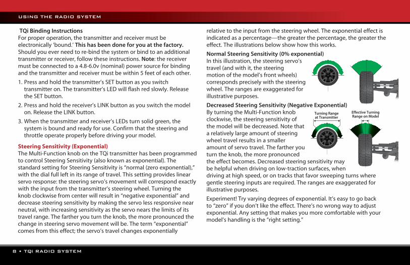
Steering Sensitivity (Exponential)TheMulti-FunctionknobontheTQitransmitterhasbeenprogrammedtocontrolSteeringSensitivity(alsoknownasexponential).ThestandardsettingforSteeringSensitivityis“normal(zeroexponential),”withthedialfullleftinitsrangeoftravel.Thissettingprovideslinearservoresponse:thesteeringservo’smovementwillcorrespondexactlywiththeinputfromthetransmitter’ssteeringwheel.Turningtheknobclockwisefromcenterwillresultin“negativeexponential”anddecreasesteeringsensitivitybymakingtheservolessresponsivenearneutral,withincreasingsensitivityastheservonearsthelimitsofitstravelrange.Thefartheryouturntheknob,themorepronouncedthechangeinsteeringservomovementwillbe.Theterm“exponential”comesfromthiseffect;theservo’stravelchangesexponentially
relativetotheinputfromthesteeringwheel.Theexponentialeffectisindicatedasapercentage—thegreaterthepercentage,thegreatertheeffect.Theillustrationsbelowshowhowthisworks.
Normal Steering Sensitivity (0% exponential)Inthisillustration,thesteeringservo’stravel(andwithit,thesteeringmotionofthemodel’sfrontwheels)correspondspreciselywiththesteeringwheel.Therangesareexaggeratedforillustrativepurposes.
Decreased Steering Sensitivity (Negative Exponential)ByturningtheMulti-Functionknobclockwise,thesteeringsensitivityofthemodelwillbedecreased.Notethatarelativelylargeamountofsteeringwheeltravelresultsinasmalleramountofservotravel.Thefartheryouturntheknob,themorepronouncedtheeffectbecomes.Decreasedsteeringsensitivitymaybehelpfulwhendrivingonlow-tractionsurfaces,whendrivingathighspeed,orontracksthatfavorsweepingturnswheregentlesteeringinputsarerequired.Therangesareexaggeratedforillustrativepurposes.
Experiment!Tryvaryingdegreesofexponential.It’seasytogobackto“zero”ifyoudon’tliketheeffect.There’snowrongwaytoadjustexponential.Anysettingthatmakesyoumorecomfortablewithyourmodel’shandlingisthe“rightsetting.”
Turning Range at Transmitter
Effective Turning Range on Model
USING THE RADIO SYSTEM

TQi RADIO SYSTEM • 9
Available Tuning AdjustmentsAllthefeaturesdescribedbelowmayalsobeaccessedusingthemenuandsetbuttonsonthetransmitterandobservingsignalsfromtheLED.Anexplanationofthemenustructurefollowsonpage14.ThefollowingitemscanbeadjustedmosteasilyusingyourmobiledevicewiththeTQiDockingBaseandtheTraxxasLinkapplication,seepage11.
YourTraxxastransmitterhasaprogrammableMulti-Functionknobthatcanbesettocontrolvariousadvancedtransmitterfunctions(settoSteeringSensitivitybydefault,seepage8).Experimentwiththesettingsandfeaturestoseeiftheycanimproveyourdrivingexperience.
Throttle Sensitivity (Throttle Exponential)TheMulti-FunctionknobcanbesettocontrolThrottleSensitivity.ThrottleSensitivityworksthesamewayasSteeringSensitivityasdescribedonpage8,butappliestheeffecttothethrottlechannel.Onlyforwardthrottleisaffected;brake/reversetravelremainslinearregardlessoftheThrottleSensitivitysetting.
Steering Percentage (Dual Rate)TheMulti-Functionknobcanbesettocontroltheamount(percentage)ofservotravelappliedtosteering.TurningtheMulti-Functionknobfullyclockwisewilldelivermaximumsteeringthrow;turningtheknobcounter-clockwisereducessteeringthrow(note:turningthedialcounter-clockwisetoitsstopwilleliminateallservotravel).BeawarethatthesteeringEndPointsettingsdefinetheservo’smaximumsteeringthrow.IfyousetSteeringPercentageto100%(byturningtheMulti-Functionknobfullyclockwise),theservowilltravelallthewaytoitsselectedendpoint,butnotpastit.ManyracerssetSteeringPercentagesotheyhaveonlyasmuchsteeringthrowastheyneedforthetrack’stightestturn,thusmakingthemodeleasiertodrive
throughouttherestofthecourse.Reducingsteeringthrowcanalsobeusefulinmakingamodeleasiertocontrolonhigh-tractionsurfaces,andlimitingsteeringoutputforovalracingwherelargeamountsofsteeringtravelarenotrequired.
Braking PercentageTheMulti-Functionknobmayalsobesettocontroltheamountofbraketravelappliedbytheservoinanitro-poweredmodel.Electricmodelsdonothaveaservo-operatedbrake,buttheBrakingPercentagefunctionstilloperatesthesamewayinelectricmodels.TurningtheMulti-Functionknobfullclockwisewilldelivermaximumbrakethrow;turningtheknobcounter-clockwisereducesbrakethrow(Note:Turningthedialcounter-clockwisetoitsstopwilleliminateallbrakeaction).
Throttle TrimSettingtheMulti-Functionknobtoserveasthrottletrimwillallowyoutoadjustthethrottle’sneutralpositiontopreventunwantedbrakedragorthrottleapplicationwhenthetransmittertriggerisatneutral.Note:YourtransmitterisequippedwithaThrottleTrimSeekmodetopreventaccidentalrunaways.Seebelowformoreinformation.
ADVANCED TUNING GUIDE
Throttle Trim Seek ModeWhen the Multi-Function knob is set to throttle trim, the transmitter
remembers the throttle trim setting. If the throttle trim knob is moved from the original setting while the transmitter is off, or while the transmitter was used to control another model, the transmitter ignores the actual position of the trim knob. This prevents the model from accidentally running away. The LED on the face of the transmitter will rapidly blink green and the throttle trim knob (Multi-Function knob) will not adjust the trim until it is moved back to its original position saved in memory. To restore throttle trim control, simply turn the Multi-Function knob either direction until the LED stops blinking.
10 • TQi RADIO SYSTEM
Steering and Throttle End PointsTheTQitransmitterallowsyoutochoosethelimitoftheservo’stravelrange(orits“endpoint”)independentlyforleftandrighttravel(onthesteeringchannel)andthrottle/braketravel(onthethrottlechannel).Thisallowsyoutofine-tunetheservosettingstopreventbindingcausedbytheservomovingsteeringorthrottlelinkages(inthecaseofanitromodel)fartherthantheirmechanicallimits.Theendpointadjustmentsettingsyouselectwillrepresentwhatyouwishtobetheservo’smaximumtravel;theSteeringPercentageorBrakingPercentagefunctionswillnotoverridetheEndPointsettings.
Steering and Throttle Sub-TrimTheSub-Trimfunctionisusedtopreciselysettheneutralpointofthesteeringorthrottleservointheeventthatsimplysettingthetrimknobto“zero”doesnotcompletelycentertheservo.Whenselected,Sub-Trimallowsfineradjustmenttotheservooutputshaft’spositionforprecisesettingoftheneutralpoint.AlwayssettheSteeringTrimknobtozerobeforemakingfinaladjustment(ifrequired)usingSub-Trim.IfThrottleTrimhasbeenpreviouslyadjusted,theThrottleTrimwillneedtobereprogrammedto“zero”beforemakingfinaladjustmentusingSub-Trim.
Setting LockOnceyou’veadjustedallofthesesettingsthewayyoulikethem,youmaywanttodisabletheMulti-Functionknobsononeofyoursettingscanbechanged.ThisisespeciallyhandyifyouoperatemultiplevehicleswithasingletransmitterviaTraxxasLink™ModelMemory.
Multiple Settings and the Multi-Function KnobItisimportanttonotethatsettingsmadewiththeMulti-Functionknobare“overlaid”ontopofeachother.Forexample,ifyouassigntheMulti-FunctiontoadjustSteeringPercentageandsetitfor50%,thenreassigntheknobtocontrolSteeringSensitivity,thetransmitterwill“remember”theSteeringPercentagesetting.Adjustmentsyoumake
toSteeringSensitivitywillbeappliedtothe50%steeringthrowsettingyouselectedpreviously.Likewise,settingtheMulti-Functionknobto“disabled”willpreventtheknobfrommakingfurtheradjustments,butthelastsettingoftheMulti-Functionknobwillstillapply.
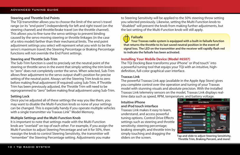
Installing Your Mobile Device (Model #6507)TheTQiDockingBasetransformsyouriPhone®oriPodtouch®intoapowerfultuningtoolthatequipsyourTQiwithanintuitive,high-definition,full-colorgraphicaluserinterface.
Traxxas LinkThepowerfulTraxxasLinkapp(availableintheAppleAppStore)givesyoucompletecontrolovertheoperationandtuningofyourTraxxasmodelwithstunningvisualsandabsoluteprecision.WiththeinstalledTraxxasLinktelemetrysensorsonthemodel,TraxxasLinkdisplaysreal-timedatasuchasspeed,RPM,temperature,andbatteryvoltage.
Intuitive iPhone and iPod touch interfaceTraxxasLinkmakesiteasytolearn,understand,andaccesspowerfultuningoptions.ControlDriveEffectssettingssuchassteeringandthrottlesensitivity;steeringpercentage;brakingstrength;andthrottletrimbysimplytouchinganddraggingtheslidersonthescreen.
ADVANCED TUNING GUIDE
Tap and slide to adjust Steering Sensitivity, Throttle Trim, Braking Percent, and more!
Failsafe Your Traxxas radio system is equipped with a built-in failsafe function
that returns the throttle to its last saved neutral position in the event of signal loss. The LED on the transmitter and the receiver will rapidly flash red to indicate the failsafe has been activated.

TQi RADIO SYSTEM • 11
Real-Time TelemetryWiththeinstalledtelemetrysensors,theTraxxasLinkdashboardcomestolifeshowingyouspeed,batteryvoltage,RPM,andtemperature.Setthresholdwarningsandlogmaximums,minimums,oraverages.Usetherecordingfunctiontodocumentyourdashboardview,withsound,sothatyoucankeepyoureyesonyourdrivingandnotmissasingleapex.
Manage up to 30 Models with Traxxas LinkTheTQiradiosystemautomaticallykeepstrackofwhatvehiclesithasboundtoandwhatsettingswereusedforeach–upto30modelstotal!TraxxasLinkprovidesavisualinterfacetonamethemodels,customizetheirsettings,attachprofiles,andlockthemintomemory.Simplychooseamodelandanypreviouslyboundtransmitter,powerthemup,andstarthavingfun.
Mobile Device Installation TheTQi™DockingBasehasauniqueclampingmechanismthatallowstheApple®iPhone®andiPodtouch®tobeeasilyinstalledandremoved.Theclamp’sself-adjustingdesignallowsittoaccommodatethewidevarietyofprotectivecasesavailableforAppleproducts.Followthesestepstoinstallyourmobiledevice:
1.SwingtheDockingBaseClampleverfrompositionA(locked)topositionB(unlocked).
2. Installyourmobiledevicebyslidingitontotheconnector.
3.EnsureyourmobiledeviceisparallelwiththeDockingBase.Slidetheincludedfoampadsbeneaththemobiledevicesoitisheldparallelwiththedockingbasewhensupportedbythepads.Thepadshavethicknessesof1,2,3and4mm,choosethebestcombinationforyourdeviceandcase,ifused.SeethechartbelowtofindthecorrectpadcombinationforiPhoneandiPodtouchmodelswithoutaccessorycases.
4.Makecertainyourmobiledeviceslidesdirectlyontotheconnectorwhenslidoverthefoampads.Whenyouaresatisfiedwiththefit,peelthebackingfromthefoampadsandapplythemtotheDockingBase.
5.ClosetheDockingBaseClampbymovingittopositionA.Confirmyourmobiledeviceissnugandsecurelyheldinplace.
Optional:TheDockingBaseClamp’s‘fingers’havesoftgripperpadsonthemtoholdun-caseddevices.Ifyourdeviceisinasoftrubbercase,thegripperpadsmayberemovedforeasierdeviceinstallationandremoval.
The customizable Traxxas Link dashboard delivers real-time rpm,
speed, temperature, and voltage data.
ADVANCED TUNING GUIDE
A B
1
2
Foam pad combination recommendations(withoutaccessorycases):
iPodtouch2nd&3rdGeneration 4mm+3mm(7mmtotal)
iPodtouch4thGeneration 4mm+3mm+2mm(9mmtotal)
iPhone3GS 3mm+2mm(5mmtotal)or4mm+1mm(5mmtotal)
iPhone4 4mm+3mm+1mm(8mmtotal)
3
12 • TQi RADIO SYSTEM
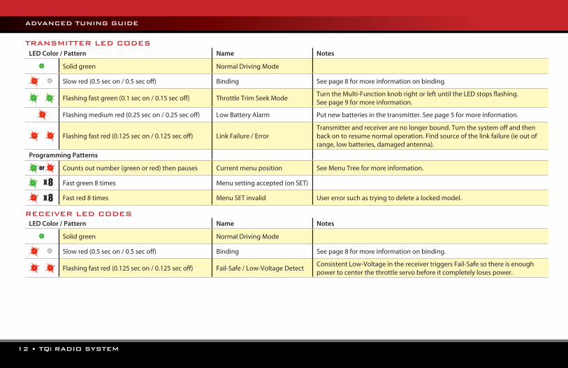
LED Color / Pattern Name Notes
Solidgreen NormalDrivingMode
Slowred(0.5secon/0.5secoff) Binding Seepage8formoreinformationonbinding.
Flashingfastgreen(0.1secon/0.15secoff) ThrottleTrimSeekModeTurntheMulti-FunctionknobrightorleftuntiltheLEDstopsflashing.Seepage9formoreinformation.
Flashingmediumred(0.25secon/0.25secoff) LowBatteryAlarm Putnewbatteriesinthetransmitter.Seepage5formoreinformation.
Flashingfastred(0.125secon/0.125secoff) LinkFailure/ErrorTransmitterandreceiverarenolongerbound.Turnthesystemoffandthenbackontoresumenormaloperation.Findsourceofthelinkfailure(ieoutofrange,lowbatteries,damagedantenna).
Programming Patterns
Countsoutnumber(greenorred)thenpauses Currentmenuposition SeeMenuTreeformoreinformation.
Fastgreen8times Menusettingaccepted(onSET)
Fastred8times MenuSETinvalid Usererrorsuchastryingtodeletealockedmodel.
LED Color / Pattern Name Notes
Solidgreen NormalDrivingMode
Slowred(0.5secon/0.5secoff) Binding Seepage8formoreinformationonbinding.
Flashingfastred(0.125secon/0.125secoff) Fail-Safe/Low-VoltageDetectConsistentLow-VoltageinthereceivertriggersFail-Safesothereisenoughpowertocenterthethrottleservobeforeitcompletelylosespower.
x 8x 8
or
TRANSMITTER LED CODES
RECEIVER LED CODES
ADVANCED TUNING GUIDE
TQi RADIO SYSTEM • 13
Traxxas Link Model MemoryTraxxasLinkModelMemoryisanexclusive,patent-pendingfeatureoftheTQitransmitter.Eachtimethetransmitterisboundtoanewreceiver,itsavesthatreceiverinitsmemoryalongwithallthesettingsassignedtothatreceiver.Whenthetransmitterandanyboundreceiverareswitchedon,thetransmitterautomaticallyrecallsthesettingsforthatreceiver.Thereisnoneedtomanuallyselectyourvehiclefromalistofmodelmemoryentries.
Model LockTheTraxxasLinkModelMemoryfeaturecanstoreuptothirtymodels(receivers)initsmemory.Ifyoubindathirty-firstreceiver,TraxxasLinkModelMemorywilldeletethe“oldest”receiverfromitsmemory(inotherwords,themodelyouusedthelongesttimeagowillbedeleted).ActivatingModelLockwilllockthereceiverinmemorysoitcannotbedeleted.
YoumayalsobindmultipleTQitransmitterstothesamemodelmakingitpossibletopickupanytransmitterandanypreviouslyboundmodelinyourcollectionandsimplyturnthemonanddrive.WithTraxxasLinkModelMemory,thereisnoneedrememberwhichtransmittergoeswithwhichmodelandthereisneveraneedtoselectanymodelfromalistofmodelmemoryentries.Thetransmitterandreceiverdoitallforyouautomatically.
To activate Model Lock:1.Switchonthetransmitterandreceiveryouwishtolock.2.PressandholdMENU.ReleasewhenthestatusLEDblinksgreen.3.PressMENUthreetimes.ThestatusLEDwillblinkgreenfour
timesrepeatedly.4.PressSET.ThestatusLEDwillblinkgreeninsingle-flashintervals.5.PressSETonce.ThestatusLEDwillblinkredoncerepeatedly.6.PressMENUonce,theLEDwillblinkredtwicerepeatedly.7.PressSET,theLEDwillblinkrapidlygreen.Thememoryisnow
locked.PressMENUandSETtoreturntodrivingmode.
Note:Tounlockamemory,pressSETtwiceatstep5.TheLEDwillblinkrapidlygreentoindicatethemodelisunlocked.Tounlockallmodels,pressMENUtwiceatstep6andthenpressSET.
To delete a model:Atsomepoint,youmaywishtodeleteamodelyounolongerdrivefromthememory.1.Switchonthetransmitterandreceiveryouwishtodelete.2.PressandholdMENU.ReleasewhenthestatusLEDblinksgreen.3.PressMENUthreetimes.ThestatusLEDwillblinkgreenfour
timesrepeatedly.4.PressSETonce.ThestatusLEDwillblinkgreenoncerepeatedly.5.PressMENUonce.ThestatusLEDwillblinkgreentwicerepeatedly.6.PressSET.Thememoryisnowselectedtobedeleted.
PressSETtodeletethemodel.PressandholdMENUtoreturntodrivingmode.
ADVANCED TUNING GUIDE
14 • TQi RADIO SYSTEM
Press MENU tomovethroughoptions.Press SET toselectanoption.
Press MENU tomovethroughoptions.Press SET toselectanoption.
Press SET toselectanoption.
Enter ProgrammingPress and hold MENU for 3 seconds
Steering Sensitivity (Expo)One Blink Red
1
ElectricOne Blink Red
1
UnlockOne Blink Red
1
Confirm DeletionOne Blink Red
1
Multi-Function KnobOne Blink Green
1
Channel SetupTwo Blinks Green
2
Mode SelectionThree Blinks Green
3
Traxxas-LinkFour Blinks Green
4
Steering (Channel 1)One Blink Green
1
Model LockingOne Blink Green
1
Shift (Channel 3)*Three Blinks Green
3
Front T-Lock (Channel 4)*Four Blinks Green
4
Rear T-Lock (Channel 5)*Five Blinks Green
5
Throttle (Channel 2)Two Blinks Green
2
Delete ModelTwo Blinks Green
2
Throttle Sensitivity (Expo)Two Blinks Red
2
NitroTwo Blinks Red
2
LockTwo Blinks Red
2
Steering % (Dual Rate)Three Blinks Red
3
Unlock AllThree Blinks Red
3
Braking % Four Blinks Red
4
Throttle TrimFive Blinks Red
5
Knob DisabledSix Blinks Red
6
Press MENU
Press MENU
Press MENU
Press MENU
Press MENU
Press SET
Press SET
Press SET
Press SET
Press SET
Press SET
Press SET
Press SET
Servo ReversingOne Blink Red
1 PressSETtoreverseservodirection.
Servo ReversingOne Blink Red
1 PressSETtoreverseservodirection.
Servo ReversingOne Blink Red
1 PressSETtoreverseservodirection.
Reset End PointsFour Blinks Red
4 PressSETtorestorefactorydefaultendpoints.
Reset End PointsFour Blinks Red
4 PressSETtorestorefactorydefaultendpoints.
Sub TrimTwo Blinks Red
2 Useknobtoadjustsub-trim.PressSETtosave.
Sub TrimTwo Blinks Red
2 Useknobtoadjustsub-trim.PressSETtosave.
End PointsThree Blinks Red
3 Usesteeringwheeltoadjust.Turnrighttodesiredendpoint,presssettosave.
Turnlefttodesiredendpointandpresssettosave.Toresetmaxthrow:LetgoofcontrolsandpressSET.
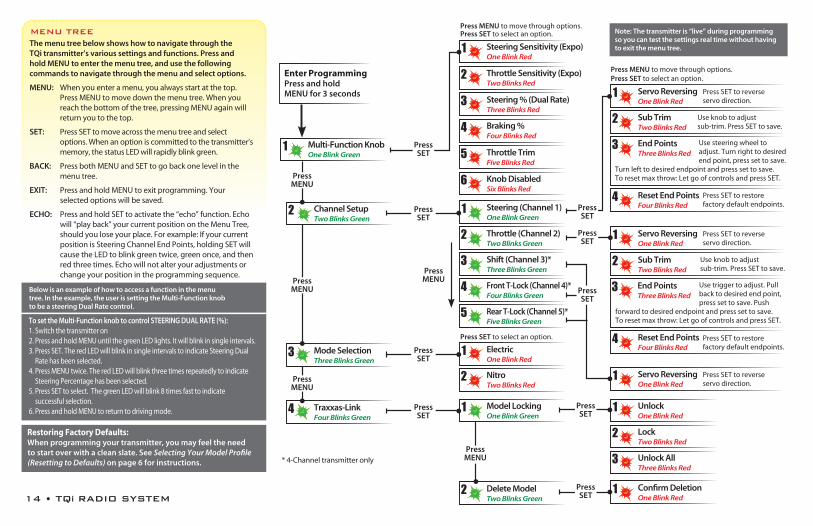
The menu tree below shows how to navigate through the TQi transmitter’s various settings and functions. Press and hold MENU to enter the menu tree, and use the following commands to navigate through the menu and select options.
MENU: Whenyouenteramenu,youalwaysstartatthetop.PressMENUtomovedownthemenutree.Whenyoureachthebottomofthetree,pressingMENUagainwillreturnyoutothetop.
SET: PressSETtomoveacrossthemenutreeandselectoptions.Whenanoptioniscommittedtothetransmitter’smemory,thestatusLEDwillrapidlyblinkgreen.
BACK: PressbothMENUandSETtogobackonelevelinthemenutree.
EXIT: PressandholdMENUtoexitprogramming.Yourselectedoptionswillbesaved.
ECHO: PressandholdSETtoactivatethe“echo”function.Echowill“playback”yourcurrentpositionontheMenuTree,shouldyouloseyourplace.Forexample:IfyourcurrentpositionisSteeringChannelEndPoints,holdingSETwillcausetheLEDtoblinkgreentwice,greenonce,andthenredthreetimes.Echowillnotalteryouradjustmentsorchangeyourpositionintheprogrammingsequence.
MENU TREE
Below is an example of how to access a function in the menu tree. In the example, the user is setting the Multi-Function knob to be a steering Dual Rate control.
To set the Multi-Function knob to control STEERING DUAL RATE (%):1.Switchthetransmitteron2.PressandholdMENUuntilthegreenLEDlights.Itwillblinkinsingleintervals.3.PressSET.TheredLEDwillblinkinsingleintervalstoindicateSteeringDual
Ratehasbeenselected.4.PressMENUtwice.TheredLEDwillblinkthreetimesrepeatedlytoindicate
SteeringPercentagehasbeenselected.5.PressSETtoselect.ThegreenLEDwillblink8timesfasttoindicate
successfulselection.6.PressandholdMENUtoreturntodrivingmode.
Note: The transmitter is “live” during programming so you can test the settings real time without having to exit the menu tree.
End PointsThree Blinks Red
3 Usetriggertoadjust.Pullbacktodesiredendpoint,presssettosave.Push
forwardtodesiredendpointandpresssettosave.Toresetmaxthrow:LetgoofcontrolsandpressSET.
Press SET
*4-Channeltransmitteronly
Restoring Factory Defaults:When programming your transmitter, you may feel the need to start over with a clean slate. See Selecting Your Model Profile (Resetting to Defaults) on page 6 for instructions.

TQi RADIO SYSTEM • 15
SetMulti-FunctionknobforSTEERINGSENSITIVITY(Expo)
Press/hold MENU greenLEDblinks
Press SET redLEDblinks
x 8Press SET to confirm greenLEDblinks(x8)
Press/hold MENU returnstodrivingmode
SetMulti-FunctionknobforTHROTTLESENSITIVITY(Expo)
Press/hold MENU greenLEDblinks
Press SET redLEDblinks
x 2Press MENU to confirm
redLEDblinks(x2)
x 8Press SET to select
greenLEDblinks(x8)
Press/hold MENU returnstodrivingmode
SetMulti-FunctionknobforSTEERINGDUALRATE(%)
Press/hold MENU greenLEDblinks
Press SET
redLEDblinks
x 3Press MENU twice redLEDblinks(x3)
x 8Press SET to select
greenLEDblinks(x8)
Press/hold MENU returnstodrivingmode
SetMulti-FunctionknobforBRAKINGPERCENTAGE(%)
Press/hold MENU greenLEDblinks
Press SET redLEDblinks
x 4Press MENU 3 times redLEDblinks(x4)
x 8Press SET to select
greenLEDblinks(x8)
Press/hold MENU returnstodrivingmode
SetMulti-FunctionknobforTHROTTLETRIM
Press/hold MENU greenLEDblinks
Press SET redLEDblinks
x 5Press MENU 4 times redLEDblinks(x5)
x 8Press SET to select
greenLEDblinks(x8)
Press/hold MENU returnstodrivingmode
AdjusttheMulti-FunctionknobuntiltheLEDturns
solidgreen.
ToDISABLE(Lock)theMulti-Functionknob
Press/hold MENU greenLEDblinks
Press SET redLEDblinks
x 6Press MENU 5 times redLEDblinks(x6)
x 8Press SET to lock
greenLEDblinks(x8)
Press/hold MENU returnstodrivingmode
ToREVERSEthedirectionofSTEERINGservo
Press/hold MENU greenLEDblinks
x 2Press MENU
greenLEDblinks(x2)Press SET
greenLEDblinksPress SET
redLEDblinks
x 8Press SET toreverseservo
direction
Press/hold MENU returnstodrivingmode
TosettheSUBTRIMoftheSTEERINGservo
Press/hold MENU greenLEDblinks
x 2Press MENU
greenLEDblinks(x2)Press SET
greenLEDblinksPress SET
redLEDblinks
x 2Press MENU
redLEDblinks(x2)
Use Multi-Function knob tosetneutral
x 8Press SET
tosaveposition
Press/hold MENU returnstodrivingmode
TosettheENDPOINTSoftheSTEERINGservo
Press/hold MENU greenLEDblinks
x 2Press MENU
greenLEDblinks(x2)Press SET
greenLEDblinksPress SET
redLEDblinks
x 3Press MENU twiceredLEDblinks(x3)
Turn steering wheel todesiredmaxleftand
righttravel
x 8Press SET
tosaveeachposition
Turn steering wheel totestsettings
IF END POINTS ARE OK:
Press/hold MENU returnstodrivingmode
IF END POINTS NEED TO BE CHANGED: Press SET
andrepeatsteps6-8
ToresettheENDPOINTSofSTEERINGservotodefaults
Press/hold MENU greenLEDblinks
x 2Press MENU
greenLEDblinks(x2)Press SET
greenLEDblinksPress SET
redLEDblinks
x 4Press MENU 3 times
redLEDblinks(x4)
x 8Press SET
toresetendpoints
Press/hold MENU returnstodrivingmode
ToREVERSEthedirectionofTHROTTLEservo
Press/hold MENU greenLEDblinks
x 2Press MENU
greenLEDblinks(x2)Press SET
greenLEDblinks
x 2Press MENU
greenLEDblinks(x2)Press SET
redLEDblinks
x 8Press SET toreverseservo
direction
Press/hold MENU returnstodrivingmode
TosettheSUBTRIMoftheTHROTTLEservo
Press/hold MENU greenLEDblinks
x 2Press MENU
greenLEDblinks(x2)Press SET
greenLEDblinks
x 2Press MENU
greenLEDblinks(x2)Press SET
redLEDblinks
x 2Press MENU
redLEDblinks(x2)
Use Multi-Function knob tosetneutral
x 8Press SET
tosaveposition
Press/hold MENU returnstodrivingmode
TosettheENDPOINTSoftheTHROTTLEservo
Press/hold MENU greenLEDblinks
x 2Press MENU
greenLEDblinks(x2)Press SET
greenLEDblinks
x 2Press MENU
greenLEDblinks(x2)Press SET
redLEDblinks
x 3Press MENU twice redLEDblinks(x3)
Use throttle trigger tosetdesiredmaxthrottle
orbrake
Press SET tosaveUsetriggertotest
IF END POINTS ARE OK:
Press/hold MENU returnstodrivingmode
IF END POINTS NEED TO BE CHANGED: Press SET
andrepeatsteps7-9
ToresettheENDPOINTSofTHROTTLEservotodefaults
Press/hold MENU greenLEDblinks
x 2Press MENU
greenLEDblinks(x2)Press SET
greenLEDblinks
x 2Press MENU
greenLEDblinks(x2)Press SET
redLEDblinks
x 4Press MENU 3 times redLEDblinks(x4)
x 8Press SET
greenLEDblinks(x8)
Press/hold MENU returnstodrivingmode
ToREVERSEthedirectionofSHIFTservo
Press/hold MENU greenLEDblinks
x 2Press MENU
greenLEDblinks(x2)Press SET
greenLEDblinks
x 3Press MENU twice
greenLEDblinks(x3)Press SET
redLEDblinks
x 8Press SET toreverseservo
direction
Press/hold MENU returnstodrivingmode
MENU TREE FORMULASTo select functions and make adjustments to the TQi transmitter without referencing the menu tree, turn your transmitter on, find the function in the left column you wish to adjust, and simply follow the corresponding steps. Always turn your
transmitter on first.
1

1100 Klein Road, Plano Texas 750741-888-TRAXXAS
owners manual
MODELS #6507, #6508, #6509
120130 KC1500-R00
“Made for iPod” and “Made for iPhone” mean that an electronic accessory has been designed to connect specifically to iPod and iPhone, respectively, and has been certified by the developer to meet Apple performance standards. Apple is not responsible for the operation of this device or its compliance with safety and regulatory standards. Please note that the use of this accessory with iPod and iPhone may affect wireless performance.
Made for· iPod touch (4th generation)· iPod touch (3rd generation)· iPod touch (2nd generation)
· iPhone 4S· iPhone 4· iPhone 3GS· iPhone 3G


