16
Models 600d/1100d OWNER’S MANUAL
Models 600d/1100d
OWNER’S MANUAL
© 1999 Directed Electronics, Inc
CONGRATULATIONS
Thank you for choosing a Directed Audiopower amplifier. Directed has been theleader in high-quality and innovativesecurity products in the U.S. since1990. Now we introduce to the caraudio industry the same winningformula - products that meet the strin-gent standards of today’s mobile elec-tronics enthusiast yet priced foranyone’s budget. Featuring high-effi-ciency MOSFET power supplies, flexibleon-board crossovers, and state-of-the-art
audio design, Directed Audio amplifierswill satisfy every music lover’s needs foryears to come. Your Directed Audiopower amplifier comes with a two yearlimited warranty if it is installed by anauthorized DEI dealer. Amplifiers notinstalled by an authorized Directeddealer are covered by a one year parts-and-labor limited warranty. Please saveyour sales receipt and refer to thewarranty section of this manual forcomplete details.
1© 1999 Directed Electronics, Inc
TABLE OF CONTENTS
High-powered car audiosystems may produce
sound pressure levels that exceed thethreshold at which hearing loss mayresult.
They may also impair a driver’s ability tohear traffic sounds or emergency vehi-cles. Use common sense and practicesafe listening habits when listening to oradjusting your audio system.
WARNING
Installation Guidelines . . . . . . . . . . . . . . . . . . . . . . . . . . . .Page 2
Amplifier Connections . . . . . . . . . . . . . . . . . . . . . . . . . . . .Page 4
Amplifier Controls . . . . . . . . . . . . . . . . . . . . . . . . . . . . . . .Page 5
Speaker Wiring Diagrams . . . . . . . . . . . . . . . . . . . . . . . . .Page 6
Crossover Setting and Gain Adjustment . . . . . . . . . . . . . . . .Page 7
Synced Gain Operation . . . . . . . . . . . . . . . . . . . . . . . . . . .Page 8
External Synced Bridged Operation . . . . . . . . . . . . . . . . . . .Page 10
Specifications . . . . . . . . . . . . . . . . . . . . . . . . . . . . . . . . .Page 12
Warranty . . . . . . . . . . . . . . . . . . . . . . . . . . . . . . . . . . . . .Page 13
© 1999 Directed Electronics, Inc 2
INSTALLATION GUIDELINES
1. Please read the owner’s manualcarefully before you install theamplifier.
2. Disconnect the battery groundterminal prior to making any elec-trical connections.
3. Check for any hazards or obstruc-tions such as gas tanks, fuel orbrake lines, and wiring harnessesbefore mounting the amplifiers.
4. Pick a mounting location that willprovide adequate access and venti-lation and protect the amplifierfrom heat, moisture, and dirt.
5. Avoid sharp metal areas whenrouting cables to the amplifier, andrun RCA cables away from thepower cables and other potentiallynoisy car harnesses.
6. The amplifier should be groundedwith a short, heavy gauge wireconnected directly to the car at abare metal surface. Make sure thatthe metal area is part of the carchassis or frame, not a separatepart with poor electrical connectionto the chassis.
7. Always fuse your power connectionat the battery within 8-10 inches ofthe battery terminal. Use a fuse orcircuit breaker rated at about 5-10
more amps than the on boardfuse(s) of the amplifier(s). Thegauge of power wire used shouldtake into account the total currentdraw of the system, and the lengthof wire used. IASCA and otherautosound competition organiza-tions have charts available for this;you can also find a chart in theMECP study guide. Minimum wiregauge recommendations for theindividual amplifiers are listed onthe specification page. It is a goodidea to use the same gauge wirefor the amplifier ground that youuse for the power wire. Be sure toexamine the battery ground cableof the vehicle and upgrade it to agauge of wire that can accommo-date the extra load created by youramplifier installation. Remember,the amplifier can only deliver itsrated output when it is not currentlimited by the power and groundsupply wires.
8. This amplifier is designed to drive aspeaker load that measures from 1-4 ohms. Keep in mind that heat isthe long-term enemy of automotiveelectronics and that the lower yourspeaker load, the more heat
© 1999 Directed Electronics, Inc
INSTALLATION GUIDELINES (continued)
3
is generated. For low impedancespeaker applications or restrictedventilation installations, an externalcooling fan may be advisable.
9. Your connections to the amplifier’sspeaker and power terminalsshould be made with crimpedspade lugs, and the battery andground connections to the vehicleshould be made with crimped ringterminals of the appropriate size(surface area is what counts);soldering the terminals aftercrimping is also recommended.
10. Due to the high-frequency MOSFETswitching power supply used in allDirected Audio amplifiers, filteringthe power cable is not generallyrequired (remember that the ampcan’t deliver full output if the powersupply is restricted). Propergrounding of the signal source ismandatory for the amplifier toreach its performance peak. If theRCA inputs are not groundedadequately via the signal source,electrical noise from the vehiclemay be picked up in the system.
4 © 1999 Directed Electronics, Inc
AMPLIFIER CONNECTIONS
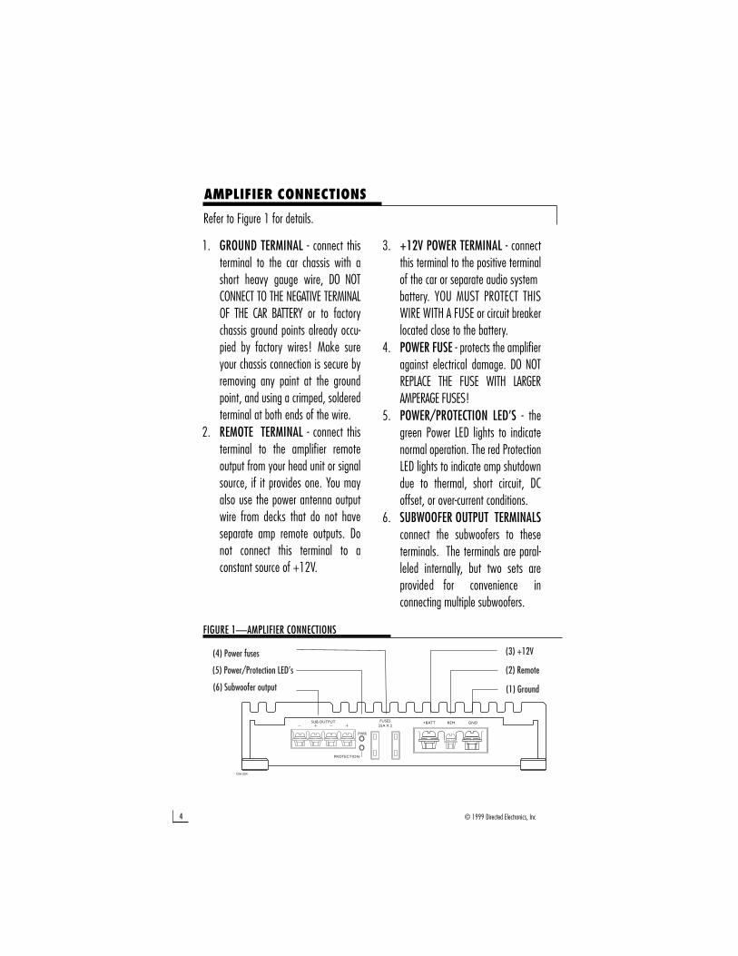
Refer to Figure 1 for details.
1. GROUND TERMINAL - connect thisterminal to the car chassis with ashort heavy gauge wire, DO NOTCONNECT TO THE NEGATIVE TERMINALOF THE CAR BATTERY or to factorychassis ground points already occu-pied by factory wires! Make sureyour chassis connection is secure byremoving any paint at the groundpoint, and using a crimped, solderedterminal at both ends of the wire.
2. REMOTE TERMINAL - connect thisterminal to the amplifier remoteoutput from your head unit or signalsource, if it provides one. You mayalso use the power antenna outputwire from decks that do not haveseparate amp remote outputs. Donot connect this terminal to aconstant source of +12V.
3. +12V POWER TERMINAL - connectthis terminal to the positive terminal of the car or separate audio system battery. YOU MUST PROTECT THISWIRE WITH A FUSE or circuit breakerlocated close to the battery.
4. POWER FUSE - protects the amplifieragainst electrical damage. DO NOTREPLACE THE FUSE WITH LARGERAMPERAGE FUSES!
5. POWER/PROTECTION LED’S - thegreen Power LED lights to indicatenormal operation. The red ProtectionLED lights to indicate amp shutdowndue to thermal, short circuit, DCoffset, or over-current conditions.
6. SUBWOOFER OUTPUT TERMINALSconnect the subwoofers to theseterminals. The terminals are paral-leled internally, but two sets areprovided for convenience inconnecting multiple subwoofers.
FIGURE 1—AMPLIFIER CONNECTIONS
5© 1999 Directed Electronics, Inc
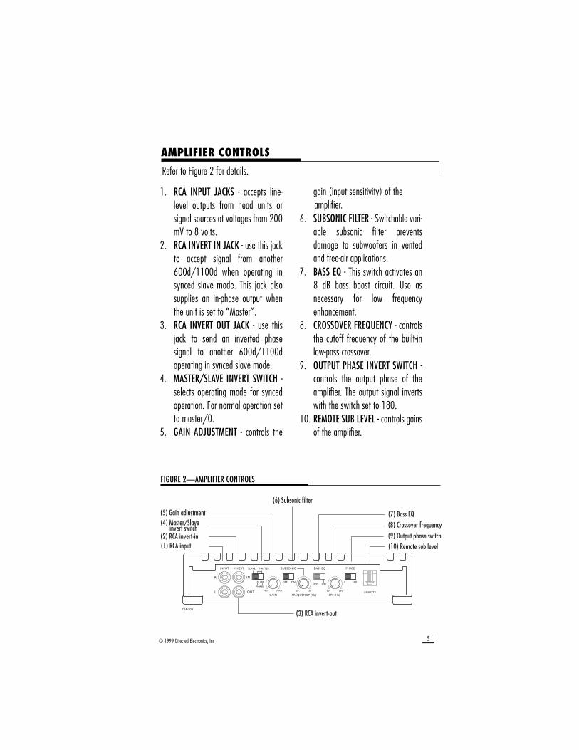
1. RCA INPUT JACKS - accepts line-level outputs from head units orsignal sources at voltages from 200mV to 8 volts.
2. RCA INVERT IN JACK - use this jackto accept signal from another600d/1100d when operating insynced slave mode. This jack alsosupplies an in-phase output whenthe unit is set to “Master”.
3. RCA INVERT OUT JACK - use thisjack to send an inverted phasesignal to another 600d/1100doperating in synced slave mode.
4. MASTER/SLAVE INVERT SWITCH -selects operating mode for syncedoperation. For normal operation setto master/0.
5. GAIN ADJUSTMENT - controls the
gain (input sensitivity) of the amplifier.
6. SUBSONIC FILTER - Switchable vari-able subsonic filter preventsdamage to subwoofers in ventedand free-air applications.
7. BASS EQ - This switch activates an8 dB bass boost circuit. Use asnecessary for low frequencyenhancement.
8. CROSSOVER FREQUENCY - controlsthe cutoff frequency of the built-inlow-pass crossover.
9. OUTPUT PHASE INVERT SWITCH -controls the output phase of theamplifier. The output signal invertswith the switch set to 180.
10. REMOTE SUB LEVEL - controls gainsof the amplifier.
AMPLIFIER CONTROLS
Refer to Figure 2 for details.
FIGURE 2—AMPLIFIER CONTROLS
6 © 1999 Directed Electronics, Inc
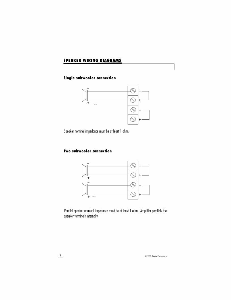
SPEAKER WIRING DIAGRAMS
Speaker nominal impedance must be at least 1 ohm.
Single subwoofer connection
Two subwoofer connection
Parallel speaker nominal impedance must be at least 1 ohm. Amplifier parallels thespeaker terminals internally.
7© 1999 Directed Electronics, Inc
CROSSOVER SETTINGS AND GAIN ADJUSTMENT
Your Directed Audio power amplifier needs to be adjusted carefully to achievemaximum performance. These are some guidelines to follow when fine-tuning theamplifier. Refer to the additional instructions on pages - for gain and crossover settingsin external synced mode.
• Because the 600d/1100d are only suited for subwoofer applications, the low-passcrossover is active at all times. The crossover point is adjustable to allow more precisesystem operation.
• Try and keep the setting low enough to prevent image smearing (you should not beable to hear male voices from the subwoofer) but not so low as to create a gapbetween the subwoofer and the mid-bass/midrange speakers. It will be to your advan-tage to spend some extra time with this adjustment, listening to familiar music orsystem set-up discs to achieve the kind of musical reproduction that you prefer.
• The gain adjustment allows you to set proper signal match for clean, quiet amplifieroperation. Start by playing some music you are familiar with. With the gain adjust-ment on the amplifier in the middle of its rotation, bring up the volume on your headunit to the 3/4 volume setting or until you start to hear distortion or clipping. If youhear distortion before you reach the 3/4 volume setting of your head unit, reduce thegain setting on the amplifier and start to raise the head unit volume again. When youcan listen to the music at or slightly above 3/4 on your head unit without audibledistortion, slowly raise the gain of the amplifier until distortion is heard, then back offthe gain until the distortion is not audible. This setting will allow you to reach fulloutput with all but the quietest of source material, while avoiding excessive noise in thesystem.
• You should take into consideration the effect that gain adjustment has on systemfrequency response and staging. Again, plan on spending some time with music thatyou know getting the gain and crossover settings the way you like. Test discs andanalyzers may help with this process, but in the end it's your ears that count - listento the music!
8 © 1999 Directed Electronics, Inc
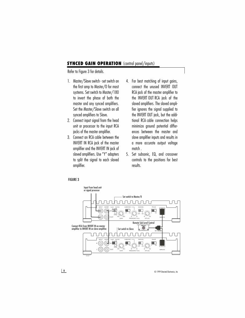
Refer to Figure 3 for details.
FIGURE 3
SYNCED GAIN OPERATION (control panel/inputs)
1. Master/Slave switch - set switch onthe first amp to Master/0 for mostsystems. Set switch to Master/180to invert the phase of both themaster and any synced amplifiers.Set the Master/Slave switch on allsynced amplifiers to Slave.
2. Connect input signal from the headunit or processor to the input RCAjacks of the master amplifier.
3. Connect an RCA cable between theINVERT IN RCA jack of the masteramplifier and the INVERT IN jack ofslaved amplifiers. Use “Y” adaptersto split the signal to each slavedamplifier.
4. For best matching of input gains,connect the unused INVERT OUTRCA jack of the master amplifier tothe INVERT OUT RCA jack of theslaved amplifiers. The slaved ampli-fier ignores the signal supplied tothe INVERT OUT jack, but the addi-tional RCA cable connection helpsminimize ground potential differ-ences between the master andslave amplifier inputs and results ina more accurate output voltagematch .
5. Set subsonic, EQ, and crossovercontrols to the positions for bestresults.
9© 1999 Directed Electronics, Inc
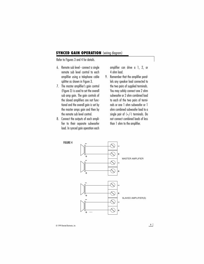
Refer to Figures 3 and 4 for details.
FIGURE 4
SYNCED GAIN OPERATION (wiring diagram)
6. Remote sub level - connect a singleremote sub level control to eachamplifier using a telephone cablesplitter as shown in Figure 3.
7. The master amplifier’s gain control(Figure 3) is used to set the overallsub amp gain. The gain controls ofthe slaved amplifiers are not func-tional and the overall gain is set bythe master amps gain and then bythe remote sub level control.
8. Connect the outputs of each ampli-fier to their separate subwooferload. In synced gain operation each
amplifier can drive a 1, 2, or 4 ohm load.
9. Remember that the amplifier paral-lels any speaker load connected tothe two pairs of supplied terminals.You may safely connect one 2 ohmsubwoofer or 2 ohm combined loadto each of the two pairs of termi-nals or one 1 ohm subwoofer or 1ohm combined subwoofer load to asingle pair of (+/-) terminals. Donot connect combined loads of lessthan 1 ohm to the amplifier.
10 © 1999 Directed Electronics, Inc
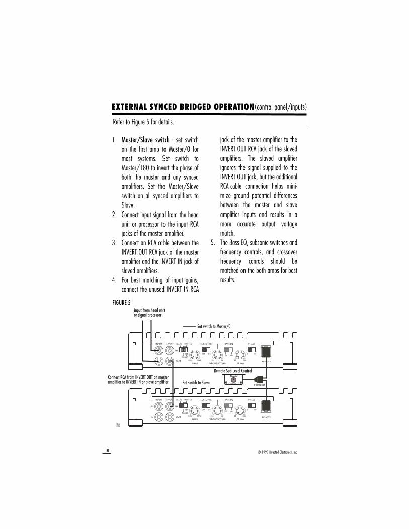
Refer to Figure 5 for details.
FIGURE 5
EXTERNAL SYNCED BRIDGED OPERATION(control panel/inputs)
1. Master/Slave switch - set switchon the first amp to Master/0 formost systems. Set switch toMaster/180 to invert the phase ofboth the master and any syncedamplifiers. Set the Master/Slaveswitch on all synced amplifiers toSlave.
2. Connect input signal from the headunit or processor to the input RCAjacks of the master amplifier.
3. Connect an RCA cable between theINVERT OUT RCA jack of the masteramplifier and the INVERT IN jack ofslaved amplifiers.
4. For best matching of input gains,connect the unused INVERT IN RCA
jack of the master amplifier to theINVERT OUT RCA jack of the slavedamplifiers. The slaved amplifierignores the signal supplied to theINVERT OUT jack, but the additionalRCA cable connection helps mini-mize ground potential differencesbetween the master and slaveamplifier inputs and results in amore accurate output voltagematch.
5. The Bass EQ, subsonic switches andfrequency controls, and crossoverfrequency conrols should bematched on the both amps for bestresults.
11© 1999 Directed Electronics, Inc
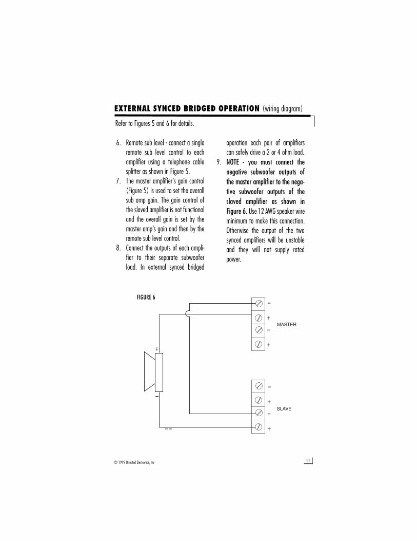
Refer to Figures 5 and 6 for details.
EXTERNAL SYNCED BRIDGED OPERATION (wiring diagram)
6. Remote sub level - connect a singleremote sub level control to eachamplifier using a telephone cablesplitter as shown in Figure 5.
7. The master amplifier’s gain control(Figure 5) is used to set the overallsub amp gain. The gain control ofthe slaved amplifier is not functionaland the overall gain is set by themaster amp’s gain and then by theremote sub level control.
8. Connect the outputs of each ampli-fier to their separate subwooferload. In external synced bridged
operation each pair of amplifierscan safely drive a 2 or 4 ohm load.
9. NOTE - you must connect thenegative subwoofer outputs ofthe master amplifier to the nega-tive subwoofer outputs of theslaved amplifier as shown inFigure 6. Use 12 AWG speaker wireminimum to make this connection.Otherwise the output of the twosynced amplifiers will be unstableand they will not supply ratedpower.
FIGURE 6
12 © 1999 Directed Electronics, Inc
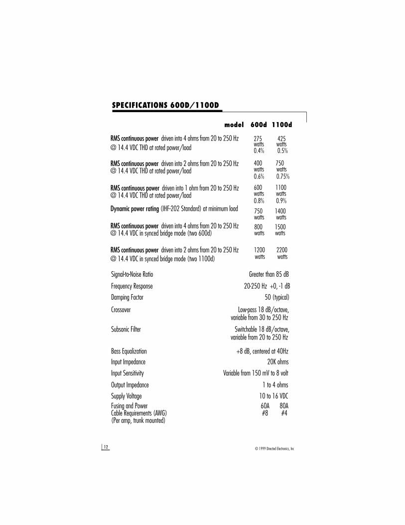
SPECIFICATIONS 600D/1100D
275 425watts watts0.4% 0.5%
model 600d 1100d
Signal-to-Noise Ratio Greater than 85 dB
Frequency Response 20-250 Hz +0, -1 dB
Damping Factor 50 (typical)
Crossover Low-pass 18 dB/octave,variable from 30 to 250 Hz
Subsonic Filter Switchable 18 dB/octave,variable from 20 to 250 Hz
Bass Equalization +8 dB, centered at 40HzInput Impedance 20K ohms
Input Sensitivity Variable from 150 mV to 8 volt
Output Impedance 1 to 4 ohms
Supply Voltage 10 to 16 VDCFusing and Power 60A 80A Cable Requirements (AWG) #8 #4 (Per amp, trunk mounted)
750 1400watts watts
400 750watts watts0.6% 0.75%
600 1100watts watts0.8% 0.9%
800 1500watts watts
1200 2200watts watts
RMS continuous power driven into 4 ohms from 20 to 250 Hz@ 14.4 VDC THD at rated power/load
RMS continuous power driven into 2 ohms from 20 to 250 Hz@ 14.4 VDC THD at rated power/load
RMS continuous power driven into 1 ohm from 20 to 250 Hz@ 14.4 VDC THD at rated power/load
Dynamic power rating (IHF-202 Standard) at minimum load
RMS continuous power driven into 4 ohms from 20 to 250 Hz@ 14.4 VDC in synced bridge mode (two 600d)
RMS continuous power driven into 2 ohms from 20 to 250 Hz@ 14.4 VDC in synced bridge mode (two 1100d)
Directed Electronics, Inc. (DEI®) promises tothe original purchaser, to replace thisproduct should it prove to be defective inworkmanship or material under normal use,for a period of two years from the date ofpurchase by the dealer as indicated by thedate code marking of the productPROVIDED the product was installed by anauthorized DEI dealer. During this two yearperiod, there will be no charge for thisreplacement PROVIDED the unit is returnedto DEI, shipping pre-paid. If the unit isinstalled by anyone other than an autho-rized DEI dealer, the warranty period will be1 year from date of purchase by the dealeras indicated by the date code marking ofthe product. During this 1 year period, therewill be no charge for this replacementPROVIDED the unit is returned to DEI, ship-ping pre-paid. This warranty is non-transfer-able and does not apply to any unit that hasbeen modified or used in a manner contraryto its intended purpose, and does not coverdamage to the unit caused by installation orremoval of the unit. This warranty is void ifthe product has been damaged by accidentor unreasonable use, neglect, improperservice or other causes not arising out ofdefects in materials or construction. ALLWARRANTIES INCLUDING BUT NOTLIMITED TO EXPRESS WARRANTY,IMPLIED WARRANTY, WARRANTY OFMERCHANTABILITY, FITNESS FOR PARTIC-
ULAR PURPOSE, AND WARRANTY OFNON-INFRINGEMENT OF INTELLECTUALPROPERTY ARE EXPRESSLY EXCLUDED TOTHE MAXIMUM EXTENT ALLOWED BYLAW, AND DEI NEITHER ASSUMES NORAUTHORIZES ANY PERSON TO ASSUMEFOR IT ANY LIABILITY IN CONNECTIONWITH THE SALE OF THE PRODUCT. DEIHAS ABSOLUTELY NO LIABILITY FOR ANYAND ALL ACTS OF THIRD PARTIESINCLUDING ITS AUTHORIZED DEALERSOR INSTALLERS. Unit must be returned toDEI, postage pre-paid, with: consumer’sname, telephone number, and address,authorized dealer’s name and address, andproduct description. IN ORDER FOR THISWARRANTY TO BE VALID, YOUR UNITMUST BE SHIPPED WITH PROOF OFINSTALLATION BY AN AUTHORIZED DEIDEALER. ALL UNITS RECEIVED BY DEI FORWARRANTY REPAIR WITHOUT PROOF OFDEI DEALER INSTALLATION WILL BECOVERED BY THE LIMITED 1 YEAR PARTSAND LABOR WARRANTY. Note: Thiswarranty does not cover labor costs for theremoval and reinstallation of the unit. BYPURCHASING THIS PRODUCT, THECONSUMER AGREES AND CONSENTS THATALL DISPUTES BETWEEN THE CONSUMERAND DEI SHALL BE RESOLVED IN ACCOR-DANCE WITH CALIFORNIA LAWS IN SAN-DIEGO COUNTY, CALIFORNIA.
13© 1999 Directed Electronics, Inc
LIMITED TWO YEAR CONSUMER WARRANTY
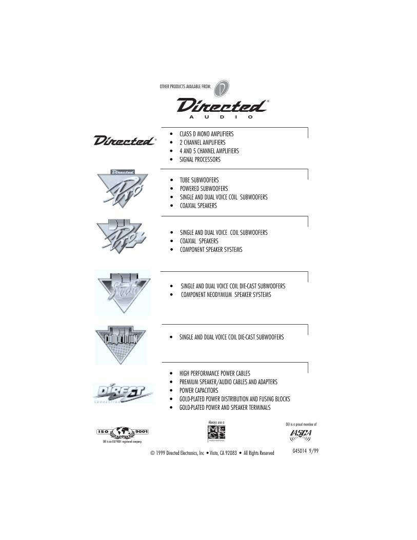
• SINGLE AND DUAL VOICE COIL SUBWOOFERS• COAXIAL SPEAKERS• COMPONENT SPEAKER SYSTEMS
© 1999 Directed Electronics, Inc • Vista, CA 92083 • All Rights Reserved G45014 9/99
Always use a DEI is a proud member of
• CLASS D MONO AMPLIFIERS• 2 CHANNEL AMPLIFIERS• 4 AND 5 CHANNEL AMPLIFIERS• SIGNAL PROCESSORS
• SINGLE AND DUAL VOICE COIL DIE-CAST SUBWOOFERS
• HIGH PERFORMANCE POWER CABLES• PREMIUM SPEAKER/AUDIO CABLES AND ADAPTERS• POWER CAPACITORS• GOLD-PLATED POWER DISTRIBUTION AND FUSING BLOCKS• GOLD-PLATED POWER AND SPEAKER TERMINALS
• TUBE SUBWOOFERS• POWERED SUBWOOFERS• SINGLE AND DUAL VOICE COIL SUBWOOFERS• COAXIAL SPEAKERS
• SINGLE AND DUAL VOICE COIL DIE-CAST SUBWOOFERS• COMPONENT NEODYMIUM SPEAKER SYSTEMS
®
OTHER PRODUCTS AVAILABLE FROM:


