88
Company XYZ Project Project Administrator Administrator Guide Guide Updated: November 20, 2007 Oro Technologies

Company XYZProject Administrator Project Administrator GuideGuide
Updated:November 21, 2007
The included information is intended
for use by Company XYZ personnel only.
Oro Technologies
www.orotechnologies.com

CompanyXYZTATL Administrator Guide
Last update: November 21, 2007 ii

CompanyXYZTATL Administrator Guide
Table of Contents
Overview............................................................................................................................1
What is TATL?..................................................................................................................1Wyse Device Manager (WDM) Installation.....................................................................1Smart Terminal Initial Configuration at HQ for Installer Handoff................................1Smart Terminal Configuration – Setting AC Loss Auto Restart Setting On..............2Smart Terminal Configuration - Installation at Remote Site........................................2Smart Terminal Configuration – After Installation at Remote Site..............................2WDM – Adding Smart Terminals to WDM to be Managed............................................3
Smart Terminal – Define WDM for Management of Device......................................................3WDM – Verifying a Smart Terminal is Found in Devices..........................................................3WDM – Define an IP or Subnet Range.....................................................................................3WDM – Finding Smart Terminal Devices..................................................................................4
WDM – Batch Updating Smart Terminals......................................................................4WDM - Understand and Creating the Smart Terminal Update (RSP) Files..............................4WDM – Smart Terminal Update File Locations........................................................................4WDM – Registering an Update with WDM................................................................................5WDM – Applying a Smart Terminal Other Package Update.....................................................5WDM – Deleting a Smart Terminal from WDM Device Manager..............................................6WDM – Applying a Smart Terminal Image Update...................................................................6WDM – Checking Status of Smart Terminal Update................................................................7WDM – Changing and Reapplying a Failed Update.................................................................7WDM – Remote Smart Terminal Re-Imaging Issue.................................................................7
WDM - Connecting Remotely and Diagnostics.............................................................8WDM - Connecting to XYZ from Public Internet via Remote Access VPN...............................8WDM – Connecting Remotely to the WDM..............................................................................8WDM – System Log................................................................................................................. 8WDM – Correcting Errors with Device Not Responding to WDM.............................................8
WDM – Administrative Functions...................................................................................9WDM – Backing up the WDM Database..................................................................................9WDM – Restoring the WDM Database.....................................................................................9
Moving Old Rapport Database to New WDM 4.51 server:........................................9Reset the RapportDB Server Table Information.........................................................9Reset the Data Access and Deleting the Old License................................................10
Smart Terminal – Connecting to a Remote Smart Terminal...................................................11
Smart Terminal Functions............................................................................................11Smart Terminal – User is Prompted for Manual Logon..........................................................11Smart Terminal – Forcing Prompt for Administrator Logon....................................................11
Last update: November 21, 2007 iii

CompanyXYZTATL Administrator Guide
Smart Terminal – Enabling Permanent Changes...................................................................12Smart Terminal – Disabling Permanent Changes..................................................................12Smart Terminal – Changing IP Information at the Smart Terminal.........................................12Smart Terminal – Changing Name and IP Information at the WDM.......................................13Smart Terminal – Verifying Boot Order...................................................................................13
Smart Terminal UserID Recommendations.................................................................13Setting Up Smart Terminal to Auto Logon..............................................................................14
Firewall Access List Setup...........................................................................................14Connecting to a Remote Firewall...........................................................................................14
Connecting to a Remote Firewall - From the XYZ HQ LAN...................................14Connecting to a Remote Firewall - From Sites Other than XYZ HQ LAN..............14
Smart Terminals: Updating a Smart Terminal in Production....................................15Setting Up Smart Terminal to Auto Logon..............................................................................15
Setting up Smart Terminals in TRIAD..........................................................................15Add IP Address to the Host Table (Using the SAM)...............................................................15Assign a Licensed Port to the Smart Terminal IP Address.....................................................16Assign CRT Printer Assignment in Ultimate...........................................................................16
TATL Information...........................................................................................................17TATL Overview Diagram........................................................................................................17TATL Installation Procedures for Smart Terminals.................................................................17
Apply TATL Recent Updates....................................................................................18Adjust and Save the TAMS and Triad Screen Layout..............................................18Set the Time Zone......................................................................................................18Add DuPont Icon on Desktop....................................................................................18Enable the Write Filter...............................................................................................18
TATL Setup Procedures for PC..............................................................................................19TATL Variable Field Locations...............................................................................................19TATL User Initiated Functions................................................................................................20
TAMSMain.psl..........................................................................................................20TRIADNextPartNo.psl..............................................................................................21TRIADPreviousPartNo.psl........................................................................................21TRIADAccept.psl......................................................................................................21TRPowerPadNext.psl.................................................................................................21TRPowerPadPrevious.psl..........................................................................................21
TATL Background Functions..................................................................................................21
TAMSStartup.psl.......................................................................................................21TAMSAssignKey.psl.................................................................................................22TRIADStartup.psl......................................................................................................22TRIADAssignKey.psl................................................................................................22TRIADUpdate.psl......................................................................................................22TRIADCurrentPart.psl...............................................................................................22
TATL Diagnostics................................................................................................................... 22
TATL Bug Report......................................................................................................22
Last update: November 21, 2007 iv

CompanyXYZTATL Administrator Guide
PowerTerm Trace Facility.........................................................................................24TATL Errors....................................................................................................................26
Error: Can’t Read “TRLine”: no such variable.........................................................26Error: TATL Only Enters a Part Line and Not the Part Number...............................26
TAMS Terminal Startup Questions..............................................................................27Setting Up PowerTerm to AutoConnect on Application Open..................................29WhatsUp Gold Network Management Installation......................................................29Network Management System – Adding Components to be Managed....................29
NMS-Installation.....................................................................................................................29NMS-Discovering Devices......................................................................................................29NMS-Defining the Router.......................................................................................................30NMS-Defining the Printer/Terminal Server.............................................................................30NMS-Defining the Smart Terminals........................................................................................31NMS-Defining the ISP Gateway.............................................................................................31NMS-Defining the DNS Server...............................................................................................31NMS-Adding Devices Manually..............................................................................................31NMS-Positioning the Devices on the Screen..........................................................................32NMS-Setting Up Dependencies..............................................................................................33NMS-Setting Email Notification to Cell Phones......................................................................33
NMS-Viewing Network Status.......................................................................................33NMS-Break-Fix Procedures..........................................................................................34Network Management System –Administrative Procedures for WhatsUp Gold.....35
NMS - Backing Up the WhatsUp Gold Database...................................................................35NMS - Restoring the WhatsUp Gold Database......................................................................35Automatically Backing Up the WhatsUp Gold Database........................................................35
Network Grooming.........................................................................................................36Network Grooming – Backup VPN Setup...............................................................................36Network Grooming – Establishing Backup Connection..........................................................36Network Grooming – Firewall Configuration...........................................................................36
Network Grooming – Firewall Configuration – Configuration Backup Before Grooming...................................................................................................................36Network Grooming – Firewall Configuration – Remote Firewall VPN Access.......37Network Grooming – Firewall Configuration – Remote MTU.................................37Network Grooming – Firewall Configuration – Verify Remote IPSec Setup...........37Network Grooming – Firewall Configuration – Verify Local IPSec Setup..............38Network Grooming – Firewall Configuration – Time Server...................................39Network Grooming – Firewall Configuration – DHCP Server.................................39Network Grooming – Firewall Configuration – Access (Internet Allow) List.........40Network Grooming – Firewall Configuration - DNS................................................42Network Grooming – Firewall Configuration – Disable Internet Access.................43Network Grooming – Firewall Configuration – Firmware Upgrade.........................43Network Grooming – Firewall Configuration – Dealing with Upgrade Issues.........44
Last update: November 21, 2007 v
CompanyXYZTATL Administrator Guide
Network Grooming – Firewall Configuration – ACL Reconfiguration after Upgrade...................................................................................................................................44Network Grooming – Firewall Configuration – Reset Smart Terminal to User Mode...................................................................................................................................45Network Grooming – Firewall Configuration – Configuration Backup After Upgrade......................................................................................................................45Network Grooming – Firewall Configuration – Configuration Restore After Upgrade......................................................................................................................45
Offsite Backups..............................................................................................................47Offsite Backups – Setup Information......................................................................................47Offsite Backups - Manually Running Backups........................................................................47Offsite Backups - Verifying Files Backed Up..........................................................................47Offsite Backups - Verifying Backups Run Successfully..........................................................48Offsite Backups – Restoring Files..........................................................................................48
Connecting to XYZ from Public Internet via Remote Access VPN...........................48Setting Up Remote Access VPN Username and Password on the Firewall/Router..49Setting Up and Connecting VPN Client on the Remote PC......................................49
Printing Configurations and Issues.............................................................................50Current Printer Configuration..................................................................................................50Desired Printer Configuration.................................................................................................50Printer Configuration Update Procedure.................................................................................50
Looming Deployment Issues Project Summary List..................................................51Remote Firewall Access List Updates....................................................................................51
Remote Firewall Access List Updates Issue Resolution and Cost............................52XYZ System and Network Diagrams............................................................................53
HQ Warehouse Configuration (1 of 2)....................................................................................53HQ Warehouse Configuration (2 of 2)....................................................................................53Triad-Atlanta Connection........................................................................................................53
WEJOEI and Electronic Cataloging (Old) Function.................................................53Typical Store Configuration (Old)...........................................................................................53Typical Store Configuration - Smart Terminal.........................................................................54
TATL Keyboard Overlay................................................................................................55Systech Terminal Server Notes....................................................................................56Change Log.....................................................................................................................57
Last update: November 21, 2007 vi

Overview This document details issues and procedures relating to the administration of the TATL system and its deployment. This document covers the following information:
- Wyse Device Manager (WDM) Installation
- Wyse Device Manager (WDM) Usage
- Smart Terminal Configuration
- Smart Terminal Deployment
- RSP for Smart Terminal Software Updates
- PC Deployment for TATL
What is TATL?TATL stands for TAMS TRIAD Link. TATL is designed to integrate the electronic cataloging function of TAMS with the invoicing and distribution warehousing functions of TRIAD. TATL is designed to work on a Smart Terminal platform using programmable terminal emulation. TATL also works on a standard PC configuration.
Wyse Device Manager (WDM) InstallationTo load the WDM on a computer, you must follow these instructions to the letter or the installation will fail:
Log on to the computer as Administrator (not as an account with admin rights). Turn off AntivirusTurn on FTPTurn on SNMPInstall WDM Create and share folder called C:\BugReport\ for bug and enhancement requests from the
users.WDM Sale Key: xxx-xxx-xxx-xxxWDM Non-activated Key: xxx-xxx-xxx-xxxWDM Activation Key: xxxxxxxWhen reactivating the key, Security Code: x
Smart Terminal Initial Configuration at HQ for Installer Handoff
1. Un-box the Smart Terminal.2. Power and plug into local XYZ network. 3. Give the WDM time to find the terminal and verify it is found using procedures in
WDM – Verifying a Smart Terminal is Found in Devices4. Execute the following procedures to prepare the Smart Terminal for installation:
a. Apply the most recent image under Images. There should only be one active image.

WDM – Applying a Smart Terminal Updateb. Changes more recent than the most recent image will be placed under Other
Package updates. Installer should apply these update after imaging the Smart Terminal.
WDM – Applying a Smart Terminal Other Package Update5. Print a copy of the TATL User Guide for each site deployed.6. Delete the Smart Terminal from the Device Manager list in the WDM.
WDM – Deleting a Smart Terminal from WDM Device Manager7. Set the AutoPower Settings to automatically power on after power failure.
Smart Terminal Configuration – Setting Auto Power On8. Hand off the Smart Terminal to the installer for installation at the remote site.
Smart Terminal Configuration – Setting AC Loss Auto Restart Setting OnIf you turn on the AC Loss Auto Restart feature, the Smart Terminals will automatically power on when power is restored after a power failure. This will enable the XYZ sites to automatically recover since the Ping script on the Smart Terminals will enable the VPN tunnels. To set the AC Loss Auto Restart Setting, perform the following procedures:
1. Power off the Smart Terminal and then Power it back on.2. While rebooting, hold the Delete key to enter Bios setup.3. Enter the password xxxxxx when prompted and press the Enter key.4. Highlight the Power Management Setup option and press the Enter key.5. Highlight the AC Loss Auto Restart option and press the Enter key.6. Select the On option and press the Enter key.7. Press the F10 key to save the configuration then Y and the Enter key to confirm. 8. Unplug the power cord and plug it back in to test the change.
Smart Terminal Configuration - Installation at Remote SiteThere is a separate set of procedures for installation of the Smart Terminal at the remote site. See the TATL Smart Terminal Installer Guide available on http://192.168.0.248.
During the installation, the installers will perform the following items:
1. Reconfigure Smart Terminal IP, DNS and Name.2. Contact HQ for port assignment in TRIAD. See partial procedures at:
Setting up Smart Terminals in TRIAD
Smart Terminal Configuration – After Installation at Remote SiteOnce the Smart Terminal is installed at the remote site, the following procedures should be followed to ensure the Smart Terminal is manageable.
1. Ensure that the Smart Terminal is defined in the WDM. If not, use the following procedures to search for the new devices:WDM – Define an IP or Subnet Range

WDM – Finding Smart Terminal Devices2. Verify the Name and IP address assignment are acceptable. If you must change this
information, follow procedures:Smart Terminal – Changing Name and IP Information at the WDM
3. Install the Smart Terminals in the WhatsUp Gold Management System using the following procedures:NMS-Adding Devices Manually NMS-Positioning the Devices on the ScreenNMS-Setting Up Dependencies
WDM – Adding Smart Terminals to WDM to be Managed
Smart Terminal – Define WDM for Management of DeviceTo make a Smart Terminal manageable by a WDM, you must configure the Smart Terminal with the IP address of the WDM.
1. Log on to Smart Terminal as Administrator password xxxxx.2. Open Start>Settings>Control Panel>Rapport.3. Define IP address to address of WDM (192.168.0.248).4. Click OK to save the change.
WDM – Verifying a Smart Terminal is Found in DevicesWhen you power up a Smart Terminal on the XYZ network, the WDM should automatically find the device and list it in the Device Manager listing. To verify a Smart Terminal has been found by the WDM, perform the following:Next, find the device.
1. Open WDM by clicking Start>All Programs>Wyse Device Manager> Wyse Device Manager 4.5.1
2. Open Console Root>WyseDeviceManager> Device Manager.3. Look for the new device in the Device Manager list. You can sort addresses by clicking
any column header. 4. Verify the column labeled Imageable has a value of Y. (If not, call support.)
WDM – Define an IP or Subnet RangeTo make the find process simpler, you can let WDM find devices on a network that has been previously installed. We will demonstrate how to set up an IP range because it is faster than subnet finds.
1. Open WDM by clicking Start>All Programs>Wyse Device Manager> Wyse Device Manager 4.5.1
2. Open Console Root>WyseDeviceManager> Configuration Manager>Networks>IP Ranges.
3. Right click IP Ranges and select New>IP Range.4. Enter the IP Range for the network. For the XYZ networks, we recommend you use the
following numbering:Start Address: 192.168.x.50 End Address: 192.168.x.160

Exclusions EnabledExclude From: 192.168.x.60Exclude To: 192.168.x.149Description: Store NameWhere x is the IP subnet for the store. Example xxxxxx is 33, so the start address would be 192.168.33.50 and the Description would be xxxxxx.
5. Click the Add button and then the Close button to add the IP Range to the list. 6. Verify that the package is now listed to the right when IP Ranges is selected.
WDM – Finding Smart Terminal DevicesNext, find the device.
5. Open WDM by clicking Start>All Programs>Wyse Device Manager> Wyse Device Manager 4.5.1
6. Open Console Root>WyseDeviceManager> Device Manager.7. Right click Device Manager and select Find Devices.8. Click the option IP Ranges radio button.9. Select from the Network List the IP Ranges you wish to use for the find. 10. Click the OK button.11. The Device Discovery window will open. When discovery is completed, click the Close
button. 12. Verify that the new devices are now listed to the right when Device Manager is selected.
NOTE: When WDM finds a smart terminal device, the device will automatically reboot.
WDM – Batch Updating Smart TerminalsWDM can be used to update the smart terminals across a network. You can use the WDM to:
- Find terminals- Change Terminal Configurations- Install New Software on Terminals- Update Existing Software on Terminals
WDM - Understand and Creating the Smart Terminal Update (RSP) FilesWDM allows the user to create an update file called a Repository Synchronization Process (RSP) file. This file contains the logic to be used to update the smart terminal configuration. The best way to create a new RSP file is to modify an existing one. You can find sample RSP files on the WDM under the directory c:\WDM\Software Updates.
WDM – Smart Terminal Update File LocationsWe have set up the folder c:\WDM\Software Updates\ as the repository for RSP and update files. Each new update should have its own subfolder.
Example: c:\WDM\Software Update\TATL\Example: c:\WDM\Software Update\PowerTerm8\

Under the specific update folder, you will locate two items:1. RSP File
Example: c:\WDM\Software Update\TATL\TATL.rsp2. Folder to hold Files for update
Example c:\WDM\Software Update\TATL\TATL\Subfolder: Program FilesSubfolder: Documents and Settings
WDM – Registering an Update with WDMOnce you have the RSP file and update files placed in the c:\WDM\Software Updates\ folder, you must register the update with WDM.
1. Open WDM by clicking Start>All Programs>Wyse Device Manager> Wyse Device Manager 4.5.1
2. Open Console Root>WyseDeviceManager>PackageManager>Other Packages
NOTE: If you intend to update a package name that already exists, I have found that you must first DELETE the existing package in order for the update to apply correctly.
3. Right click Other Packages and select New>Package.4. Select Register a Package from a Script File (.RSP).5. Use the browse function to find the RSP file in the subfolder under c:\WDM\Software
Updates6. Verify that the package is now listed to the right when Other Packages is selected.
WDM – Applying a Smart Terminal Other Package UpdateOnce you have the RSP file and update files placed in the c:\WDM\Software Updates\ folder and registered with WDM, you can apply the update with WDM.
1. Open WDM by clicking Start>All Programs>Wyse Device Manager> Wyse Device Manager 4.5.1
2. Open Console Root>WyseDeviceManager>Update Manager3. Right click Device Manager and select New>Update.4. Select Other Package and click the Next button.5. You will see the registered updates listed on the Package Distribution Wizard form.
Highlight the desired update package and click the Next button.6. Select the group to receive the updates and click the Next button.7. Select the devices to receive the update. Note the following functions for this screen:
a. Holding the Shift key down while clicking allows you to select multiple contiguous entries.
b. Holding the Control key down while clicking allows you to select multiple non-contiguous entries.
c. Clicking on any column header enables you to sort by that column. For example, if you wanted all the xxxxx locations, you could click the IP Address column header and all of the 192.168.33.x devices would be grouped together…use the Shift key to select the contiguous group of entries.
8. Once the device entries are highlighted, click the Next button.

9. Specify when you wish the update to occur and click the Next button twice to deploy the update.
NOTE: If a user is at the terminal, they will be given a prompt that allows the following 3 options:
a. Apply the update now by clicking the Update Now button.b. Apply the update in 5 minutes by clicking the 5 Minute Delay button.c. Do nothing and the update will happen in 2 minutes automatically.
10. Verify that the package is now listed to the right when Other Packages is selected.
NOTE: When WDM updates a smart terminal device, the device will automatically reboot twice. The update process will disable the smart terminal device for approximately 5 to 10 minutes depending on the size of the update.
WDM – Deleting a Smart Terminal from WDM Device ManagerOnce you have configured a Smart Terminal at the HQ location and are ready to deploy it to the remote location, you should delete it from the WDM Device Manager list so it does not confuse the person configuring the system and does not create duplicate entries after it is installed.
1. Open WDM by clicking Start>All Programs>Wyse Device Manager> Wyse Device Manager 4.5.1
2. Open Console Root>WyseDeviceManager>Device Manager3. Right click the device to delete and select the Delete option.4. Confirm the deletion.
WDM – Applying a Smart Terminal Image UpdateOnce you have the RSP file and update files placed in the c:\WDM\Software Updates\ folder and registered with WDM, you can apply the update with WDM. 1. Open WDM by clicking
Start>All Programs>Wyse Device Manager> Wyse Device Manager 4.5.12. Open Console Root>WyseDeviceManager>Update Manager3. Right click Update Device Manager and select New>Update.4. Select Images and click the Next button.5. You will see the registered updates listed on the Package Distribution Wizard form.
Highlight the desired update package and click the Next button.6. Select the group to receive the updates and click the Next button.7. Select the devices to receive the update. Note the following functions for this screen:
a. Holding the Shift key down while clicking allows you to select multiple contiguous entries.
b. Holding the Control key down while clicking allows you to select multiple non-contiguous entries.
c. Clicking on any column header enables you to sort by that column. For example, if you wanted all the xxxxxx locations, you could click the IP Address column header and all of the 192.168.33.x devices would be grouped together…use the Shift key to select the contiguous group of entries.
8. Once the device entries are highlighted, click the Next button.

9. Specify when you wish the update to occur and click the Next button twice to deploy the update. NOTE: If a user is at the terminal, they will be given a prompt that allows the following 3 options:
a. Apply the update now by clicking the Update Now button.b. Apply the update in 5 minutes by clicking the 5 Minute Delay button.c. Do nothing and the update will happen in 2 minutes automatically.
10. Verify that the package is now listed to the right when Images is selected.
NOTE: When WDM updates a smart terminal device, the device will automatically reboot twice. The update process will disable the smart terminal device for approximately 5 to 10 minutes depending on the size of the update.
WDM – Checking Status of Smart Terminal Update Once you have applied the update, you can then check the status of the update in the WDM.
1. Open WDM by clicking Start>All Programs>Wyse Device Manager> Wyse Device Manager 4.5.1
2. Open Console Root>WyseDeviceManager>Update Manager>Scheduled Packages3. The jobs and their status are on the right side. If a job fails, check the status code.
WDM – Changing and Reapplying a Failed UpdateIf an update you applied fails, you must delete and re-register the update.
1. Open WDM by clicking Start>All Programs>Wyse Device Manager> Wyse Device Manager 4.5.1
2. Open Console Root>WyseDeviceManager>Update Manager>Scheduled Packages. The jobs and their status are on the right side. If a job fails, check the status code.
3. First, you must delete Fail and or Delete the Device Updates assigned to the Update Package.
4. After the Device Updates are deleted, Open Console Root>WyseDeviceManager>PackageManager>Other Packages
5. Right click on the package to be replaced and delete it.6. After making the necessary changes to the RSP file or upload, repeat the procedures for
Registering a New Update above.
WDM – Remote Smart Terminal Re-Imaging IssueIt is not currently possible to reimage the Smart Terminal configuration over the existing VPN tunnel as it is currently configured. The Secure Computing firewalls do not support BootP Helper, and hence, if there is a need to reimage a Smart Terminal, the following steps must be executed to restore the device to service:
1. Uninstall the device2. Transport the Smart Terminal to XYZ HQ3. Reimage the Smart Terminal on the XYZ local network4. Transport the Smart Terminal back to the store
5. Reinstall the Smart Terminal 6. Reconfigured for that store network
WDM - Connecting Remotely and DiagnosticsConnecting to the WDM differs depending on where you are located. If you are in the HQ location you can connect to
“XYZ” “192.168.0.248” Requires VPN Connection First
HQ Location Yes YesXYZ Store YesFrom the Public Internet
Yes Yes
WDM - Connecting to XYZ from Public Internet via Remote Access VPNIf you are connecting to the WDM from a location outside the XYZ network on the public Internet, you must first establish a VPN tunnel to the XYZ network. Do this by following the procedures Connecting to XYZ from Public Internet via Remote Access VPN.
WDM – Connecting Remotely to the WDMYou can remotely connect to the WDM PC using the Remote Desktop Connection in Windows.
1. From your computer, click Start>All Programs>Accessories>Communications>Remote Desktop Connection.
2. Enter the IP address of the WDM which is 192.168.0.248.3. You will be prompted to enter the username Administrator password xxxxx.
WDM – System Log To check the boot order on a Smart Terminal, perform the following:
1. Restart (or start) the terminal and continue to press the Delete key.2. When prompted for the password, type xxxxx and press the Enter key.3. Select Advanced Bios Features and press the Enter key.4. Verify the First Boot Device is LAN.
WDM – Correcting Errors with Device Not Responding to WDMAt times, a device may not take updates from the WDM. This may happen to a single device or to multiple devices. It is likely the logs in the WDM are corrupted. Perform the following steps to correct:
1. Close the Wyse Device Manager application.2. Open c:\WDM\SupportTools\MDTools_3[1].0.exe. (Download from ftp://ftp-
us.wyse.com/Pub/Support/Tools/MDTools/ if not available on the system.)3. Click the … next to Enter Database Server to fill in the correct value.4. Click Default User checkbox.5. Select under Which Table to View, the Server option and click the View button.6. Select under Tablet to Clear the log for the SystemLog table. Click the Clear button
and confirm by typing the word DELETE when prompted.

7. Select under Tablet to Clear the log for the Server table. Click the Clear button and confirm by typing the word DELETE when prompted.
8. Under Services (Start>Control Panel>Administrator Tools>Services), restart/start the following services in the order displayed:
World Wide Web PublishingRapport4MSSQL$RapportDBHServerInit
9. Now watch the log by clicking the WDM Service Logs icon in the lower right corner of the system tray. You should see DHCP requests when the next terminal restarts.
WDM – Administrative Functions
WDM – Backing up the WDM Database1. Close the Wyse Device Manager application.2. Click Start>Control Panel>Administrative Tools>Services.3. Right click and stop the MSSQL$Rapport & Rapport4 services. Make sure the services are
completely stopped before proceeding.4. Copy the two files located from c:\Program files\Wyse\WDM\database
File name - Rapport4.ldf, and Rapport4.mdf to the file location C:\TATL\Backups\WDM\Program Files\Wyse\WDM\Database\.
5. The files will be backed up automatically when the Remote Data Backups auto-backup runs.
WDM – Restoring the WDM Database
Moving Old Rapport Database to New WDM 4.51 server:Stop the MSSQL$RapportDB services by clicking Start>Run> services.msc and click the OK button.
1. Right click MSSQL$RapportDB and select Stop to stop the service.2. From the folder c:\program files\Wyse\WDM\Database\ copy the files Rappor4.ldf, and
Rapport4.mdf 3. Rename the files to Rappor4.ldf_new, and Rapport4.mdf_new4. Start the MSSQL$RapportDB services by clicking Start>Run> services.msc and click
the OK button. 5. Right click MSSQL$RapportDB and select Start to start the service.
Reset the RapportDB Server Table InformationThe MDTools can be used on both the Workgroup and the Enterprise versions, but the procedure to use the SQL Enterprise Manager for the WDM Enterprise version has also been included. For the WDM Workgroup Edition
1. Download the MDTools utilities and the .NET infrastructure files from ftp://ftp-us.wyse.com/Pub/Support/Tools/MDTools/
2. Verify that .NET is installed on your server. Install if necessary before continuing
3. Copy MDTools to your desktop
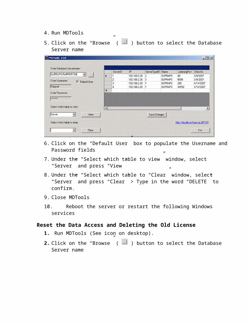
4. Run MDTools

5. Click on the “Browse” ( ) button to select the Database Server name
6. Click on the “Default User” box to populate the Username and Password fields
7. Under the “Select which table to view” window, select “Server” and press “View”
8. Under the “Select which table to “Clear” window, select “Server” and press “Clear” > Type in the word “DELETE” to confirm.
9. Close MDTools
10. Reboot the server or restart the following Windows services
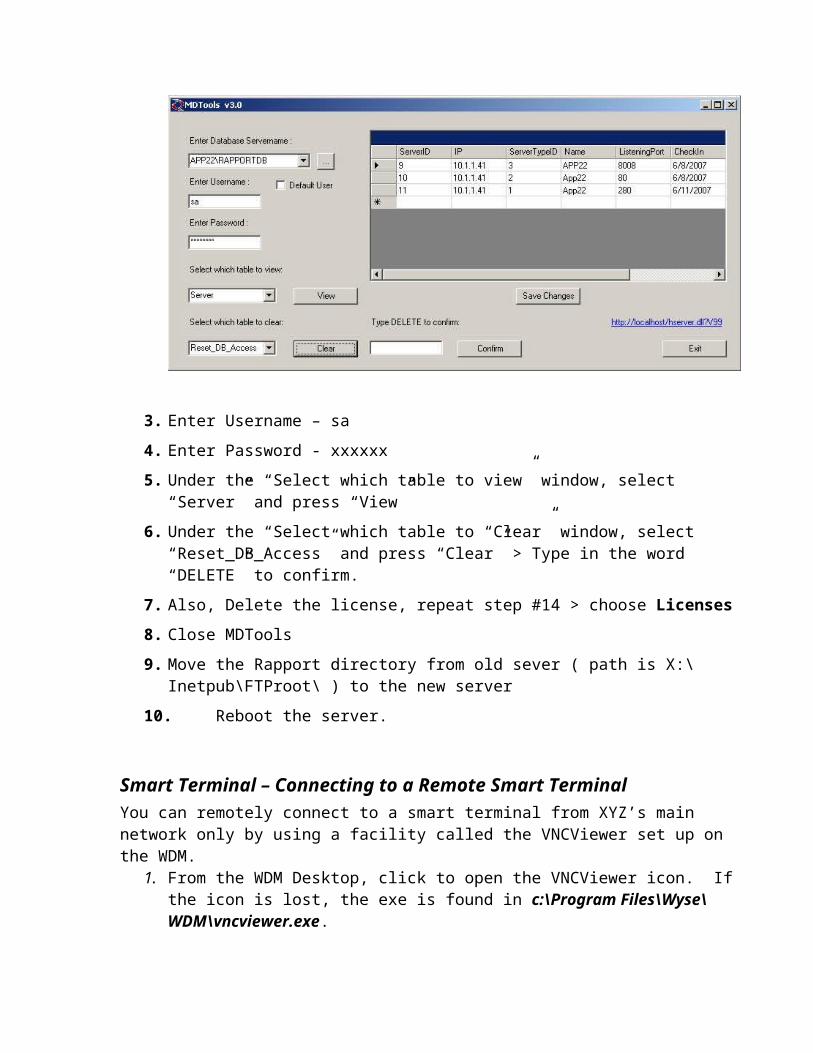
Reset the Data Access and Deleting the Old License1. Run MDTools (See icon on desktop).
2. Click on the “Browse” ( ) button to select the Database Server name

3. Enter Username – sa
4. Enter Password - xxxxxx
5. Under the “Select which table to view” window, select “Server” and press “View”
6. Under the “Select which table to “Clear” window, select “Reset_DB_Access” and press “Clear” > Type in the word “DELETE” to confirm.
7. Also, Delete the license, repeat step #14 > choose Licenses
8. Close MDTools
9. Move the Rapport directory from old sever ( path is X:\Inetpub\FTProot\ ) to the new server
10. Reboot the server.
Smart Terminal – Connecting to a Remote Smart TerminalYou can remotely connect to a smart terminal from XYZ’s main network only by using a facility called the VNCViewer set up on the WDM.
1. From the WDM Desktop, click to open the VNCViewer icon. If the icon is lost, the exe is found in c:\Program Files\Wyse\WDM\vncviewer.exe.
2. Enter the IP address of the device to which you wish to connect. (Note: It may be helpful to find the IP address in the WDM Device Manager or by displaying the DHCP IP Address list from the remote firewall.)
3. The icon will disappear and it will look as if nothing is happening…4. At the Smart Terminal will flash a message that the WDM wishes to connect. If a user is
at the terminal, they can reply and allow you in immediately. If no user responds, the terminal will wait 2 minutes and let you connect.
5. You will receive a prompt for the device password. Enter XXXX and click OK.6. If you are prompted for Control-Alt-Delete to log in, click in the very upper left hand
corner, and one of the options will be Send Ctrl-Alt-Delete. Select this option.7. Enter the username and password for the device. Default username for the Smart
Terminal is Administrator password xxxxxxx.
Smart Terminal Functions
Smart Terminal – User is Prompted for Manual LogonFrom time to time, a user might be prompted with a login password on the smart terminal. If the user gets a prompt to log on to the smart terminal, the user name is User and password xxxx.
Smart Terminal – Forcing Prompt for Administrator LogonThe Smart Terminals should be configured to auto logon to the User userid. If you need to make changes to the Smart Terminal, you must log into the Smart Terminal as Administrator. This procedure may be done over the VNCViewer connection or locally.
1. While logged onto the Smart Terminal User userid, click Start>Shut Down.2. Select the option for Logoff, but do not click OK yet.
3. Hold the right shift key down while you click OK and keep holding the right shift key until you see the login prompt.
4. At the login prompt, enter username Administrator password xxxxxx.
Smart Terminal – Enabling Permanent Changes Any changes made to the Smart Terminal will be lost when power cycling the Smart Terminal unless the Smart Terminal is configured with the Write Filter Disabled. Before making any permanent changes to the Smart Terminal, you must disable the write filter.
1. Log on as Administrator using procedures defined in Smart Terminal – Forcing Prompt for Administrator Logon
2. Disable the Write Filter by clicking the Red Button icon on the administrator desktop labeled Write Filter Disabled.
3. The Smart Terminal will reboot automatically.4. Log on as Administrator using procedures defined in
Smart Terminal – Forcing Prompt for Administrator Logon5. Make whatever permanent changes required to the Smart Terminal.
Smart Terminal – Disabling Permanent ChangesAfter making permanent changes to the Smart Terminal with the Write Filter Disabled, you will want to set the Write Filter Enabled to protect the Smart Terminal memory from being overwritten with undesirable information such as viruses, cookies or other information. Enabling the Write Filter prevents permanent updates to the Smart Terminal memory.
1. Log on as Administrator using procedures defined in Smart Terminal – Forcing Prompt for Administrator Logon
2. Enable the Write Filter by clicking the Green Button icon on the administrator desktop labeled Write Filter Enabled.
3. The Smart Terminal will reboot automatically.4. Log on as User and verify that the change is permanent.
Smart Terminal – Changing IP Information at the Smart TerminalAfter deployment at the remote site, the Smart Terminal should be configured with a static IP address. It is recommended that you assign the static IP address after all other information is updated on the Smart Terminal. Each Smart Terminal must have a unique IP address within the network where it will be used.
1. Log on as Administrator using procedures defined in Smart Terminal – Forcing Prompt for Administrator Logon
2. Disable the Write Filter for permanent changes using procedures defined in Smart Terminal – Enabling Permanent Changes
3. While logged onto the Smart Terminal userid Administrator, click Start>Settings>Control Panel>Network Connection>Local Area Connection>Properties.
4. Scroll down the list to highlight Internet Protocol (TCP/IP) and click Properties.5. Click Use the following IP Address and enter the
Static IP Address of the device (192.168.xx.150 to 192.168.xx.160), Subnet Mask: 255.255.255.0

Default Gateway: 192.168.xx.1006. Click Use the following DNS Server Addresses and enter the
Preferred DNS Server: 192.168.xx.100Alternate DNS Server: 151.164.14.201
7. Click OK button twice.8. Enable the Write Filter for permanent changes using procedures defined in
Smart Terminal – Disabling Permanent Changes
Smart Terminal – Changing Name and IP Information at the WDMAfter deployment at the remote site, the Smart Terminal should be configured with a static IP address. It is recommended that you assign the static IP address after all other information is updated on the Smart Terminal. Each Smart Terminal must have a unique IP address within the network where it will be used. You can update the Smart Terminal from the WDM using the following procedures:
1. Open WDM by clicking Start>All Programs>Wyse Device Manager> Wyse Device Manager 4.5.1
2. Open Console Root>WyseDeviceManager>Device Manager3. Right click the terminal you wish to update and select the Change Device
Information option to rename the Smart Terminal.4. Change the Computer Name to the defined pattern (e.g. xxxxx1, xxxxx2) and
click the OK button.5. Right click the terminal you wish to update and select the Change Network
Information option to update addressing information on the Smart Terminal.6. Click the Use the following IP address radio button and enter the following IP
Address informationIP Address of the device (192.168.xx.150 to 192.168.xx.160), Subnet Mask: 255.255.255.0Gateway: 192.168.xx.100
7. Click the OK button.8. Click the Use the following DNS Server Addresses radio button and enter the
following DNS informationPreferred DNS Server: 192.168.xx.100Alternate DNS Server: 151.164.14.201
9. Click the OK button.
Smart Terminal – Verifying Boot OrderTo check the boot order on a Smart Terminal, perform the following:
1. Restart (or start) the terminal and continue to press the Delete key.2. When prompted for the password, type xxxxx and press the Enter key.
Smart Terminal – Enabling Permanent Changes
Smart Terminal UserID Recommendations The smart terminals automatically log on to userid User. It is likely that XYZ will want to retain usage of the User userid rather than set up password protected userids for the initial deployment. The following chart illustrates the implications of userid usage on the terminals:

Setting Up Smart Terminal to Auto Logon1. Log on to Smart Terminal as Administrator password xxxxx.2. Open Start>Settings>Control Panel>Winlog.3. Click the entry Enable Auto Logon.4. Click OK to save the change.
Firewall Access List SetupXYZ has decided to implement a firewall access list such that counter personnel are limited to accessing sites on the Internet which are specifically required for XYZ business functions. In addition, DHCP server capabilities are to be enabled such that new devices may work on the network simply by requesting IP addressing information. The following procedures document how to configure the SG300 firewall router for these capabilities:
Connecting to a Remote Firewall
Connecting to a Remote Firewall - From the XYZ HQ LANWhen connecting to a remote firewall from the XYZ HQ LAN, you can simply browse the IP address of the remote firewall. For example, browsing http://192.168.xx.100 in Internet Explorer will connect to the administrator’s console of the remote firewall. Username and Password for the firewalls is root/xxxxxx.
Connecting to a Remote Firewall - From Sites Other than XYZ HQ LANWhen connecting to a remote firewall from a location other than the XYZ HQ LAN, you msut first connect to a PPTP VPN connection from your computer.
1. In Windows XP, click Start>Control Panel>Network Connections>Create a New Connection>Connect to the network at my workplace>Virtual Private Network.
2. Give the connection a name like XYZCity.3. If prompted, select the Do Not Dial the Initial Connection radio button. 4. When prompted for host name or IP address, provide the public IP address
of the remote firewall. This might be obtained from the location \\192.168.0.248\documentation\XYZNetworkDetails.xls.
5. When prompted for the Username/password, enter XYZadmin/xxxxxxx.
You can simply browse the IP address of the remote firewall. For example, browsing http://192.168.xx.100 in Internet Explorer will connect to the administrator’s console of the remote firewall. Username and Password for the firewalls is root/xxxxxxx.

Note that you will lose general Internet access while connected to the VPN. To disconnect, right click the VPN Icon in the lower right hand corner of the screen and click Disconnect.
Smart Terminals: Updating a Smart Terminal in ProductionFrom time to time, updates will be applied to the Smart Terminals. Due to the production nature of the XYZ network, it is critical that strict procedures be followed when performing updates.
a. See WDM – Batch Updating Smart Terminals for Details of applying updates to terminals.
b. Open \\192.168.0.248\ChangeLog\ChangeLog.doc to make changes to the Change Log.
The following general process flow will ensure continued productivity for the XYZ network:1. Develop update in “Update Pilot” configuration folder.2. Apply PILOT UPDATE to a single Pilot Smart Terminal.3. Validate PILOT UPDATE was applied successfully.4. Document PILOT UPDATE in Change Log.5. Employ PILOT MIGRATION TO PRODUCTION procedures.6. Document PILOT MIGRATION TO PRODUCTION in Change Log.7. Schedule ALL SITES UPDATE for after-hours deployment.8. Document ALL SITES UPDATE in Change Log.
Setting Up Smart Terminal to Auto Logon1. Log on to Smart Terminal as Administrator password xxxxx.2. Open Start>Settings>Control Panel>Winlog.
Setting up Smart Terminals in TRIADOnce you have a Smart Terminal configured with its IP address, you must allow that IP address to be used in the TRIAD system. This is necessary since the Triad system has a limited number of licenses and the licenses are governed by port assignments in the TRIAD system. At the time of this writing XYZ has 150 available licensed ports in the TRIAD system.
Add IP Address to the Host Table (Using the SAM)1. Log in as root (see Susan for username/password). This should be done at the TRIAD
HP console terminal.2. Type TERM=vt100 and press the Enter key.3. At the # prompt, type sam and press the Enter key.4. Select Networking and Communications and press the Enter key.5. Select Hosts and press the Enter key.6. Select Local Host File and press the Enter key.7. Tab to Actions>Add and add the new Smart Terminal IP address to the list.8. At the # prompt type exit and press the Enter key.
Assign a Licensed Port to the Smart Terminal IP Address1. Log in as root (see Susan for username/password). This should be done at the TRIAD
HP console terminal.2. Type TERM=vt100 and press the Enter key.3. At the # prompt, type ultconfigroot and press the Enter key.4. Choose option 3 (lines).5. Cursor down to find the IP address you wish to map to a license port and press the Enter
key.6. Enter the number associated with the IP address (e.g. 230) and press the Enter key.7. Select F for fixed.8. Enter the port number to assign. Ports are available at least up to 499 since the phantom
port is 500. Note that you will likely want to re-assign an existing port assigned to a dumb terminal to a new smart terminal to retain appropriate printer assignments. For example, the xxxxx dumb terminals used ports 146, 145 and 147 and when the smart terminals were placed, we reassigned these ports to the smart terminals so printers did not need to be reassigned in Ultimate.
9. Type y to commit the change or q to quit.10. Reboot the HP system to apply the changes.
Assign CRT Printer Assignment in UltimateThere are several ports available in the system. The first several ports are set up as LPT printer ports, and the remainder are serial ports which must be assigned in Ultimate.
1. ###See Susan for these procedures.
TATL Information
TATL Overview Diagram
TATL Installation Procedures for Smart Terminals1. Power on Smart Terminal. It will auto login. (Note: Make sure the USB flash stick is
not plugged into the terminal or it will fail to boot.)2. Click Start>Shut Down and select Log off. Hold Shift key down while clicking OK
button to get login prompt.3. Log on to Smart Terminal (userid Administrator, password xxxxxx).4. Skip this step if the Red indicator light is on. If the Green (Write Filter Enabled)
indicator is on, disable the Write Filter (Write Filter Disable) on the smart terminal (see smart terminal operations guide for details).Smart Terminal – Enabling Permanent Changes
5. Skip this step if the Red indicator light is on. Smart Terminal will reboot and you must repeat the login sequence. (Hold down shift key again to log off and log in as Administrator).
6. Run the TATLSetup.msi program on the computer. This program will install all the necessary files for TATL to run correctly. (Version 20070517 and beyond will install on

both PCs and Smart Terminals.) (You may use Start>Run and then type \\192.168.0.248\TATL\, press the Enter key, and execute TATLSetup.msi.)
7. When prompted, change the option for installation from Just Me to Everyone.
Apply TATL Recent Updates1. Click Start>Run and enter \\192.168.0.248\TATL and click the OK button.2. Open the Updates folder.3. Click Edit>Select All.4. Click Edit>Copy.5. While holding the Windows key down, press the E key to open Windows Explorer (My
Computer) 6. Click and select the XPe (C:) folder.7. Click Edit>Paste.8. Click the Yes to All button each time you are prompted.
Adjust and Save the TAMS and Triad Screen Layout (Note: TATL Updates MUST be applied first for this section to work.)
9. Open the TATL application by clicking on the Desktop TATL icon.10. Adjust the applications on the screen as you would like them to display.11. On both the Triad and TAMS sessions, click File>Save Terminal Configuration12. Close Triad and TAMS and verify the screen positions were saved by reopening TATL.
Set the Time ZoneDouble click the time (e.g. 7:33 AM) in the lower right corner of the screen.
1. Click the Time Zone tab.2. Click the pulldown list and select (GMT-06:00) Central Time (US and Canada).3. Click the OK button.
Add DuPont Icon on Desktop
1. Right Click on the Desktop and select New>Shortcut. The Create Shortcut screen opens.2. In the blank field, enter http://www.performancecoatings.dupont.com 3. Click the Next button.4. In the blank field, enter the name DuPont Coatings.5. Click the Finish button.6. Move the new icon to the bottom left of the screen so it is visible under the TATL screens
when they are open.7. Username currently available is XYZ33, password is xxxxxx.
Enable the Write Filter1. Enable the Write Filter (Write Filter Enable) using the following procedure:
Smart Terminal – Disabling Permanent Changes2. Terminal will auto login. Run TATL to ensure that it works properly.
Virtual Memory Problems – You may run into Virtual Memory Problems when loading applications on the Smart Terminal. If this happens, you may need to increase the size of the
virtual memory. The document to do this is located on the Wyse web site www.wyse.com…search the support knowledge base for Solution 11340.
TATL Setup Procedures for PCPC InstallationA TATLSetup.msi installer has been created for XYZ use. The following steps should be used when installing TATL on a standard PC or laptop.
1. Install PowerTerm Interconnect (downloadable from www.ericom.com web site). Cost of update is approximately $150/user for individual licenses.
2. Run the TATLSetup.msi program on the computer. This program will install all the necessary files for TATL to run correctly.
TATL Variable Field LocationsTATL is very flexible and can be custom configured to adapt to changes in the TRIAD or TAMS system. To change variables for field positions in TATL, install TATL on your computer and view the file
c:\Program Files\Ericom Software\Powerterm\UserDefinedVariables.txt
Review the notes in the file for details on each field and its use.

TATL User Initiated Functions
TAMSMain.pslFunction Key: Alt-F8 in TAMS onlyLocation: c:\program files\ericom software\powerterm\Description: TAMSMain.psl copies the parts from the TAMS screen and places the part numbers in a file for the TRIADUpdate program to pick up. The user should only execute the TAMSMain.psl program when viewing the parts listing screen in TAMS.
Detail: TAMSMain will perform various functions such as:1. Identify if the proper screen is displayed when execution begins.2. Validate that the first page of parts is listed…otherwise move up to the first page.3. Gather the parts from the TAMS page and place them in a file.4. Move down the pages of TAMS parts to ensure that all parts are acquired.
The user must execute TAMSMain from the TAMS Parts list screen:
TRIADNextPartNo.pslFunction Key: Alt-->Location: c:\program files\ericom software\powerterm\Description: TRIADSkip is initiated from the keyboard when the user desires to move from the current part number to the next part number on the PowerPad list.
TRIADPreviousPartNo.pslFunction Key: Alt-<-Location: c:\program files\ericom software\powerterm\Description: TRIADBack is initiated from the keyboard when the user desires to move from the current part number to the previous part number on the PowerPad list.
TRIADAccept.pslFunction Key: Alt-EnterLocation: c:\program files\ericom software\powerterm\Description: TRIADAccept is initiated from the keyboard when the user desires to place the current part number denoted by *** on the PowerPad into the TRIAD application.
TRPowerPadNext.pslFunction Key: Clicking “Next” in PowerPadLocation: c:\program files\ericom software\powerterm\Description: TRIADPowerPadNext reads the next page of parts values to be displayed on the PowerPad.
TRPowerPadPrevious.pslFunction Key: Clicking “Previous” in PowerPadLocation: c:\program files\ericom software\powerterm\Description: TRIADPowerPadPrevious reads the next page of parts values to be displayed on the PowerPad.
TATL Background Functions
TAMSStartup.pslFunction Key: Automatic at TAMS startupLocation: c:\program files\ericom software\powerterm\Description: Marginally Functional. TAMStartup.psl is designed to run automatically at the start of the TAMS session startup. This program automatically logs the user into the TAMS application. The program functions marginally due to the continual monthly change of the TAMS messages at system startup. To log on manually to the TAMS system, follow the procedures defined in the TAMS Login section of this manual.
Note: In the two months that we have developed for the TATL interface, the screen interface for TAMS startup has changed 4 times. We expect the login script is something that if desired, must be maintained as updates to TAMS are applied.

TAMSAssignKey.pslFunction Key: Automatic at TAMS startupLocation: c:\program files\ericom software\powerterm\Description: TAMSAssignKey.psl starts automatically with TAMS. This program assigns the keys for the TATL TAMS interface.
TRIADStartup.pslFunction Key: Automatic at TRIAD startupLocation: c:\program files\ericom software\powerterm\Description: TRIADStartup.psl is designed to run automatically at the start of the Triad session startup. This program automatically logs the user into the TRIAD application up to the point of entering the authorization code.
TRIADAssignKey.pslFunction Key: Automatic at TRIAD startupLocation: c:\program files\ericom software\powerterm\Description: TRIADAssignKey.psl starts automatically with TRIAD. This program assigns the keys for the TATL TRIAD interface.
TRIADUpdate.pslFunction Key: Auto when Alt-Enter or Alt-<--> is pressed.Location: c:\program files\ericom software\powerterm\Description: TRIADUpdate.psl reads the parts from the file created by TAMSMain.psl. It then populates the powerpad with the parts so that the user can enter one or more part numbers into TRIAD from the PowerPad.
TRIADCurrentPart.pslFunction Key: Automatic at TRIAD startupLocation: c:\program files\ericom software\powerterm\Description: TRIADCurrentPart.psl is called from the TRPreviousPartNo.psl and TRNextPartNo.psl programs. This program determines the current part number in the PowerPad list that is used. It also read or re-reads the parts list into the PowerPad.
TATL Diagnostics
TATL Bug ReportFunction Key: Alt-F12Location: c:\program files\ericom software\powerterm\BugReport.pslDescription: TATL Bug Report submits an enhancement or Bug Report to XYZ HQ personnel and includes the current screen snapshots that may have caused a problem or encouraged the request for enhancement.
Detail: TATL’s design includes a Bug Report mechanism that allows any user to report a bug or enhancement with the click of a button. The TATL Bug Report is executed in either the TAMS or Triad session using the Alt-F12 function.

Location of Bug Reports: The TATL Bug Report looks in the UserDefinedVariables.txt file for the variable called XYZProblemDirectory. A sample value for the XYZProblemDirectory might be \\192.168.0.29\TATLBugs\.
User Information: When the TATL Bug Report is executed, the user is prompted to provide information that can be used for follow-up and resolution of the problem. This information includes:
User’s NameUser’s Phone NumberUser’s Store LocationDescription of Enhancement or Bug
This information is included in a file called ProblemReport date-time.txt.Example: ProblemReport 2007-Apr-30-11-11-57.txtExample Content:
The ProblemReport File is created on Mon Apr 30 11:11:55 2007 Name: Steve SeyerPhone: 636-675-5555Store: 41Problem or Enhancement: Need to make the interface for the TAMS to TRIAD TATL link update automatically.
Screen Snapshots: In order to provide adequate diagnostic data to recreate the problem, screen snapshots of the TAMS screens are replicated and sent to the XYZProblemDirectory location.
This information is included in a file called TAScreenTrackFile# date-time.txt. If multiple files are required for multiple screen snapshots, then # is incremented accordingly. Example: TAScreenTrackFile1 2007-Apr-30-11-11-57.txtExample Content: Customer... 00000 Cash Customer 000-0000 Customer... 00000 Cash Customer 000-0000 Employee... 0001 No. One Seq Part Line Description Available PC Price CV List Vehicle: 2002 Buick Park Avenue Job Type: Alignment - Front 1. 2643639 NCP Cam / Crank Bolt Kit - Front Susp Cam Bolt; Camber Plus or Minus 1 1/2 0 2 12.39 19.60 Degree; Cam Bolt w/ Adjustment Fence 2. 2643644 NCP Cam / Crank Bolt Kit - Front Susp Camber Plus or Minus 1 3/4 Degree; 1 1 18.59 29.88 For Non-Slotted 2-Bolt Macpherson Struts; ForReplacement Of 16mm Bolts; May Be Used On Vehicles Equipped w/ AftermarketSlotted Struts w/ Addition Of Our Adapter Plate Include w/ Cams; Per CarQuantity Varies by Application. Minimum Required Shown 3. 2643638 NCP Cam / Crank Bolt Kit - Front Susp

Crank Adjusting Bolt; For Replacement Of 2 2 15.19 24.34 16mm Bolts; Camber Plus or Minus 1 1/4Degree (END) ESC-Exit, ARROWS-Scroll, F6-Subtotal, F7-Back Field, F8-Invoicing, F11-Add to Invoice Enter seq. number or function:___
PowerTerm Trace FacilityFunction Key: Options>Start Trace and Options>Stop TraceLocation: In the PowerTerm applicationDescription: The PowerTerm trace facility captures activity on the sessions. Should a TATL program fail, it may be necessary to collect diagnostic information using the trace facility.
Detail: The PowerTerm Trace facility captures raw information that travels to and from the PowerTerm sessions. It is important to run the trace facility on the appropriate session (TAMS or Triad) to capture the correct information. It is also important to time the capture of information such that only relevant information is captured, otherwise the capture logs will be too large to find the diagnostic information.
Location of Trace Reports: C:\Program Files\Ericom Software\PowerTerm
Example: capture.logExample Content:
PowerTerm CAPTURE file version 6================================
Send: 0000610:05:38.720000: 37 35 31 32 38 32 |751282 |
Key : 1 013A 00314 |VTK_RETURN|10:05:38.72=======
Send: 0000110:05:38.720000: 0D |. |
Recv: 0000110:05:38.780000: 37 |7 |
Recv: 0000210:05:38.78

0000: 35 31 |51 |
Recv: 0001110:05:38.850000: 1B 59 27 24 37 35 31 10 07 32 38 |^Y'$751..28 |
Recv: 0023010:05:38.860000: 32 1B 59 23 60 20 20 20 20 20 20 30 2E 30 30 0D |2^Y#` 0.00.|0010: 0A 1B 59 27 24 47 4E 41 37 35 31 32 38 32 20 20 |.^Y'$GNA751282 |0020: 20 20 20 20 20 20 20 20 20 0F 1B 59 28 22 1B 4B | .^Y("^K|0030: 10 02 20 20 20 20 20 20 20 20 20 20 20 20 20 20 |.. |0040: 20 10 17 55 4F 4D 3A 20 20 20 10 25 53 49 3A 31 | ..UOM: .%SI:1|0050: 20 20 20 10 34 43 51 3A 20 20 10 41 4C 49 53 54 | .4CQ: .ALIST|0060: 3A 20 38 32 30 2E 37 36 10 56 51 4F 48 3A 20 20 |: 820.76.VQOH: |0070: 20 20 20 20 20 51 43 4D 3A 1B 30 50 0E 10 60 20 | QCM:^0P..` |0080: 20 20 20 20 20 10 71 20 20 20 20 20 30 0D 0A 0F | .q 0...|0090: 1B 59 37 4D 52 45 4F 3A 10 56 51 41 56 3A 20 20 |^Y7MREO:.VQAV: |00A0: 20 20 20 20 20 51 50 4F 3A 1B 30 50 0E 10 49 20 | QPO:^0P..I |00B0: 20 20 20 20 20 10 60 20 20 20 20 20 30 10 71 20 | .` 0.q |00C0: 20 20 20 20 30 0F 1B 59 27 55 20 20 30 2E 30 30 | 0.^Y'U 0.00|00D0: 10 60 20 20 20 35 34 37 2E 31 37 1B 59 27 39 31 |.` 547.17^Y'91|00E0: 20 20 20 20 10 25 | .% |
TATL ErrorsFrom time to time, the user may receive errors using TATL. Following are a list of common errors that may occur when using TATL.
Error: Can’t Read “TRLine”: no such variableApplication: TRIADCause: User has hit the Alt->, Alt<- or Alt-Enter key too many times in sequence. Resolution: User must slow down moving from one part to another such that the TRIADBack.psl and TRIADSkip.psl programs have time to process the request to move from one part number to another. Alternatively, the user may click a part in the PowerPad using the mouse. This can be an effective method for dealing with parts that are far down the list from the current pointer.
Error: TATL Only Enters a Part Line and Not the Part NumberApplication: TRIADCause: User has tried to enter a part using the keyboard, and it failed to enter the part number. Resolution: This problem occurs when the user hits the Enter key and not the Alt-Enter Sequence. User must remember to hit the ALT-Enter key sequence to input the entire part number.

TAMS Terminal Startup QuestionsWhen first connecting a terminal to the TAMS system, it prompts for the following information:


Setting Up PowerTerm to AutoConnect on Application OpenSet this script as the start-up script, and set your Terminal-> Setup -> Preferences to 'Auto Connect'
set system-name myHostIP#Where 'myHostIP is the IP or DNS name of your hostsession openwait 5 secondssession closeset system-name myHostIP2session openwait 5 secondsrun Function_Script.psl#where 'Function_Script.psl' is the name of your other script.
WhatsUp Gold Network Management InstallationTo load the WhatsUp Gold on a computer, you must follow these instructions to the letter or the installation will fail:
Log on to the computer as Administrator (not as an account with admin rights). Note: You must log on directly to the computer itself. The process will fail if you try to
use remote desktop connection into the system. Turn off AntivirusEnsure FTP and HTTP are turned on.Ensure SNMP is turned on.Install WhatsUp Gold. WhatsUp Gold Key: ******
Network Management System – Adding Components to be Managed
NMS-InstallationInstall the IPSwitch WhatsUp Gold product on a system running XP Pro or Server 2003.Serial # is NP2-0000420083Registered Serial # at www.ipswitch.com/register to receive license code.License code is 878531 941613 039895 676523 482873.
Log on to the WhatsUp Gold system as Administrator password xxxxxx.
NMS-Discovering DevicesTo add devices to the WhatsUp Gold network, perform the following procedures:
1. Log on to the WhatsUp Gold system as Administrator password xxxxxxx. (You can remote into 192.168.0.248 using remote desktop connection.)

2. Open Start>All Programs>Ipswitch WhatsUp Gold Standard Edition v11>WhatsUp Gold Standard Edition.
3. Click Tools>Discover Devices. You will want to add a single network group at a time. For example, add all the xxxxx terminals at one time.
4. Select IP range scan and click the Next button.5. Enter 192.168.xx.0 for Start address and 192.168.xx.255 for End address where xx is
the number of the location and click the Next button.6. Enter Public for SNMP read communities and leave Windows credentials field blank
and click the Next button.7. On the Active Performance Monitors to Scan screen, ensure Ping is checked in the top
list and Interface Utilization and Ping Lantency and Availability is checked in the lower list and click the Next button.
8. Allow the system time to find the devices on the network. When the scan is completed, click the Next button.
9. Select Apply this action policy and select NotifyViaCellPhoneEmail in the pulldown list and click the Next button.
10. Click the Finish button to complete the find.11. You will notice a new group under XYZ Network has been added on the left side of the
screen. The name of the new group will start with IPRangeScan. 12. Right click on the new IPRangeScan name and select Rename. Enter the name of the
site such as xxxxx. Press the Enter key to accept the changed name.
NMS-Defining the Router 1. With the new name group selected, on the right side of the screen, you will notice the
discovered devices. Double click the device ending in address 100 to display the Device Properties screen for the router.
2. Ensure the General tab is selected on the left side menu.3. Change the Display Name from 192.168.xx.100 to Router.4. Change the Host Name to a descriptive device name such as xxxxxx Router. (Note that
Host Name shows up in email alerts that go out to admin personnel.)5. Click the Device type pulldown and select Router.6. Click the OK button to save the entry.
NMS-Defining the Printer/Terminal Server1. Double click the device ending in address 110 to display the Device Properties screen
for the terminal server.2. Ensure the General tab is selected on the left side menu.3. Change the Display Name from 192.168.xx.110 to Terminal Server.4. Change the Host Name to a descriptive device name such as xxxxxx Terminal
Server/Printer. (Note that Host Name shows up in email alerts that go out to admin personnel.)
5. Click the Device type pulldown and select Printer.6. Click the OK button to save the entry.

NMS-Defining the Smart Terminals1. Double click any device ending in address 150 to 160 to display the Device Properties
screen for the terminal server.2. Ensure the General tab is selected on the left side menu.3. Change the Display Name from 192.168.xx.150 to 160 to the name of the location
concatenated with the device number…for example xxxxxx1.4. Change the Host Name to a descriptive device name such as xxxxxx Smart Terminal 1.
(Note that Host Name shows up in email alerts that go out to admin personnel.)5. Click the Device type pulldown and select Workstation.6. Click the OK button to save the entry.
NMS-Defining the ISP Gateway1. Connect (Browse) the network’s router (http://192.168.xx.100)2. Click the Diagnostics tab at the bottom left side of the screen.3. Under Internet, note the Gateway and DNS server addresses (the first DNS will suffice).4. Switch back to the WhatsUp Gold console, right click on the site name (left column…
e.g. xxxxxx) and select New Device.5. In the IP Address field, enter the IP address of the Gateway (e.g. 24.182.142.121). Click
the Add Device Immediately without Scanning checkbox and click the OK button.6. In the Display Name field (General tab), enter ISP Gateway.7. Change the Host Name to a descriptive device name such as xxxxxx ISP Gateway.
(Note that Host Name shows up in email alerts that go out to admin personnel.)8. In the Device Type pulldown, select Router and click the OK button.9. Position the ISP Router icon to the right of the site Router icon.
NMS-Defining the DNS Server1. Click on the site name (left column…e.g. xxxxxx) and select New Device.2. In the IP Address field, enter the IP address of the DNS server (e.g. 24.217.0.5). Click
the Add Device Immediately without Scanning checkbox and click the OK button. (See previous section for finding DNS Server address.)
3. In the Display Name field (General tab), enter ISP DNS.4. In the Device Type pulldown, select Web Server and click the OK button.5. Change the Host Name to a descriptive device name such as xxxxxx DNS Server. (Note
that Host Name shows up in email alerts that go out to admin personnel.)6. Position the ISP DNS icon to the right of the site Router icon and below the ISP
Gateway icon.7. In the top menu of the WhatsUp Gold screen, there is a cloud icon. Click, size and
position the cloud to represent the Internet.
NMS-Adding Devices ManuallyTo add devices manually such as Smart Terminals to the WhatsUp Gold network, perform the following procedures:
1. Log on to the WhatsUp Gold system as Administrator password xxxxxxx. (You can remote into 192.168.0.248 using remote desktop connection.)

2. Open Start>All Programs>Ipswitch WhatsUp Gold Standard Edition v11>WhatsUp Gold Standard Edition.
3. Right click in the white space in the right frame of the screen. 4. Select New>New Device.5. Enter the IP address of the device in the IP Address field (e.g. 192.168.116.150) and
click the OK button.6. Click the General tab and populate the following fields similar to that shown in the
following Smart Terminal example. Ensure the match the device type appropriately.:
7. Click the Notes tab and populate the information similar to the following example and click the OK button:
xxxxxx xx192.168.5.xStore # 5Store Contact is: Richard WaltherMain Phone number: 573-xxxxxxx
NMS-Positioning the Devices on the Screen1. Move the devices on the screen such that the site devices are on the left side of the screen
and the site router is on the right, and to the right further, the cloud and to the right further, the ISP Gateway and ISP Name Server to create a logical visual of the site network.
2. You may also add text to each screen like the name of the site and lines representing connections. These are not critical items.

NMS-Setting Up Dependencies WhatsUp Gold is smart enough to know that some devices will never respond to polling if an upstream device has failed. You can “Set Up Dependencies” for the remote devices at a site so that reporting is limited to only the failing component. For example, terminals and terminal servers all have an “Up Dependency” on their local router.
Setting Remote Device Dependency on Router1. For each device behind the remote router (Smart Terminals, Terminal Servers and any
other computers), right click on each device icon and select Set Dependencies>Set Up Dependency On.
2. Next, click the router at that site.3. The Up Dependency screen will open. Click the OK button to apply All Active
Monitors to the selection.
Setting Remote Router Dependency on ISP Gateway4. Once you have completed each site device, next right click the router icon and select Set
Dependencies>Set Up Dependency On.5. Next, click the ISP Gateway for that site.6. The Up Dependency screen will open. Click the OK button to apply All Active
Monitors to the selection.
NMS-Setting Email Notification to Cell PhonesThe WhatsUp Gold system can be configured to notify users via email of outages and restoration of service. This can be particularly beneficial for support personnel who cannot watch the monitor continuously. Since every cell phone has an email address, these messages can be targeted to support personnel cell phones as text messages very easily, and this can be an effective way to keep support personnel aware of network availability. To set the email addresses of cell phones to be notified, change the action policies using the following procedures:
1. In the WhatsUp Gold system, click Configure>Action Library. 2. Select the policy Send Down 5 Emails and click the Edit button.3. In the Mail to field, enter the email address of the cell phone you wish to use (e.g.
[email protected]. For multiple email notifications, separate each email address by a comma. Click the OK button to save.
4. Select the policy Send Up 5 Emails and click the Edit button.5. In the Mail to field, enter the email address of the cell phone you wish to use (e.g.
[email protected]. For multiple email notifications, separate each email address by a comma. Click the OK button to save.
NMS-Viewing Network StatusThe WhatsUp Gold system has the ability for remote viewing. You can see the status of the network from any computer in the network. To view the network status:
1. Connect to the NMS by browsing: http://192.168.0.248:8080.2. Enter username and password both as admin.3. Click the Devices tab to view the network map.

4. Ensure the Map View tab at the bottom of the screen is selected.5. If a site is no longer green, double click the site icon to see what components have failed.
NMS-Break-Fix ProceduresA. If all sites are green,
a. Network is 100% operational.B. If all site icons are red,
a. All users are disconnected from TATL (Triad and TAMS). The problem is likely with the HQ Internet connection.
b. Review lights on the HQ Router…possibly restart (Susan or Mike).c. Contact AT&T to recover.
C. If a single site icon is red,1. Double click the site icon to see what has failed.2. If all icons in the site are red,
a. The problem is probably with peering point between AT&T and the remote ISP. That site is unable to reach TATL (Triad and TAMS).
b. In a dos prompt (Start>run>cmd) run a traceroute to the remote ISP Gateway IP address (ex: tracert 24.182.142.121>c:\temp\tracert.txt).
c. Contact AT&T and ask to be connected to the NOC for a peering point issue.d. Send the output of the trace (c:\temp\tracert.txt) to the contact at the AT&T NOC.
3. If the router and all site devices in a site are not green (but ISP Gateway is green)a. The problem is with the DSL or Cable service. That site is unable to reach TATL
(Triad and TAMS).b. Review lights on the DSL/Cable Modem.c. Review lights on remote router.d. Restart DSL/Cable Modem and router.e. Test site communication again (ping the remote router…Start>cmd…ping
192.168.xx.100).f. Review lights again.g. Contact the site’s ISP if no reply from ping.
4. If only a site ISP DNS is not green, a. Users at the site cannot reach Prolink but they can reach TATL.b. Check with site for Prolink problems.c. If problems, contact sites ISP and notify them of the DNS Server outage.
5. If only a site Terminal Server is not green, a. Users at the site cannot print. b. Contact the site and restart the print server.c. Replace print server if necessary.
6. If only a site Smart Terminal is not green (e.g. xxxxx1),a. The user Smart Terminal is off the network.b. Reboot the Smart Terminal using the power switch on the front of the unit.c. Check to see if Smart Terminal has picked up dynamic address (192.168.xx.50 or
51…)d. Check the device again by pinging its IP address (Start>Cmd….ping
192.168.xx.15x).e. Replace the Smart Terminal if necessary if no reply from ping.
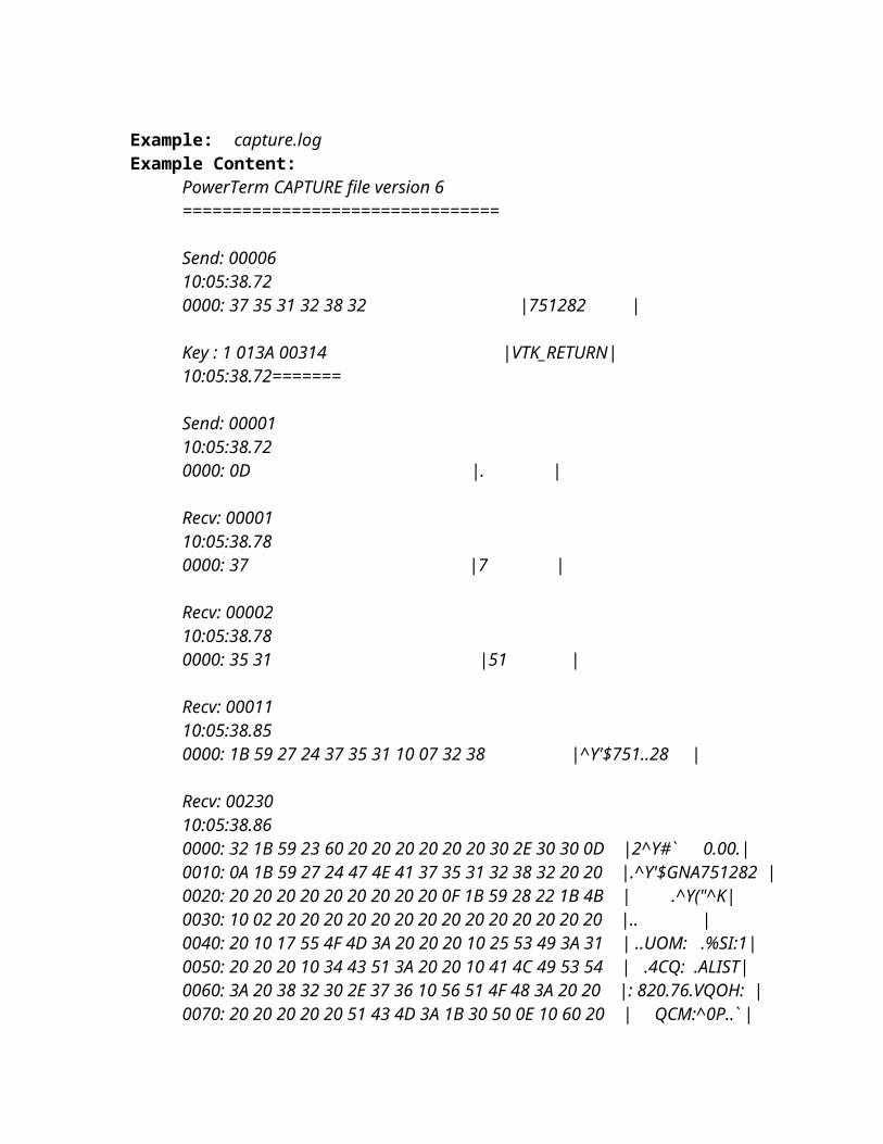
Network Management System –Administrative Procedures for WhatsUp Gold
NMS - Backing Up the WhatsUp Gold DatabaseThe WhatsUpGold database should be backed up and stored somewhere other than the TMS computer whenever significant changes are made to the system. The following procedures detail the backup procedures:
1. Open WhatsUp Gold.2. The WhatsUp database. This can be done from the WhatsUp console by selecting Tools
> Database Utilities > Back Up SQL Database. Enter the location for the backup file and filename (recommended naming structure: 200xMMDD-WhatsUpGold.dat)
3. In the registry, the Network Monitor key from HKEY_LOCAL_MACHINE\SOFTWARE\Ipswitch.
4. In the registry, the WHATSUP key from HKEY_LOCAL_MACHINE\SOFTWARE\Microsoft\Microsoft SQL Server.
5. The WhatsUp installation folder. The default location for this is C:\Program Files\Ipswitch\WhatsUp
NMS - Restoring the WhatsUp Gold Database
To restore a WhatsUp installation:
1.) Reinstall the same version of WhatsUp Professional as was running when the backup was created. Both MSDE and WhatsUp Professional must be reinstalled to the same paths. If you are prompted to restart the server after installation, you must do so before continuing to Step 2.2.) Shut down the Ipswitch WhatsUp Engine service.3.) Shut down the MSSQL$WHATSUP service.4.) Open the registry editor, backup and then delete the following keys:HKEY_LOCAL_MACHINE\SOFTWARE\Microsoft\Microsoft SQL Server\WHATSUPHKEY_LOCAL_MACHINE\SOFTWARE\Ipswitch\Network Monitor5.) Import the two registry keys from your backup.6.) Restart only the MSSQL$WHATSUP service.7.) Open the WhatsUp console, and select Tools > Database Utilities > Restore SQL Database to restore the SQL database from your backup.8.) Restart the WhatsUp machine.
Automatically Backing Up the WhatsUp Gold Database
To automatically make a complete backup of the database, you can setup a scheduled task in Windows that calls a batch file.In the batch file, execute the following command:
OSQL -E -n -D WhatsUp -Q "BACKUP DATABASE WhatsUp TO DISK = 'drive:\path\WhatsUp.dat' WITH INIT"

The batch file should be located in the MSDE program installation directory. The default location is C:\Program Files\Microsoft SQL Server\80\Tools\Binn.
In our example, we wish to place our backup in C:\Program Files\Microsoft SQL Server\MSSQL$WHATSUP\Data, so the batch file would contain:
OSQL -E -n -D WhatsUp -Q "BACKUP DATABASE WhatsUp TO DISK = 'C:\Program Files\Microsoft SQL Server\MSSQL$WHATSUP\Data\WhatsUp.dat' WITH INIT"
Note: This process will overwrite any data in an existing WhatsUp.dat
Network Grooming
Network Grooming – Backup VPN Setup The remote XYZ sites can connect over the Big River Internet connection in the event that the AT&T network is unavailable. This is done via a VPN connection into the Big River router using the following VPN connection settings. This information was built into the Image file for the Smart Terminals and requires no additional effort to put in place.
IP Address for VPN tunnel termination: xx.xx.xx.xxUserID: backupatt/XYZxxxxx
Network Grooming – Establishing Backup ConnectionThe remote XYZ sites can connect over the Big River Internet connection in the event that the AT&T network is unavailable. The remote user can establish a connection without any assistance from HQ
1. On the remote Smart Terminal Desktop, click the icon labeled Big River Backup Path.
2. When the Splash screen opens, click the Connect button.3. Re-open the TATL application and the session will reestablish over the
backup path.
Network Grooming – Firewall Configuration
Network Grooming – Firewall Configuration – Configuration Backup Before GroomingWhen changes are made to the Firewall Configuration, a backup should be completed.
1. On remote firewall, click Advanced>Configuration Files>Save and Restore>Save Configuration. (Note: Do not click the link for Configuration Files, but the link for Save and Restore under the Configuration Files section.)
2. Enter firewall password (xxxxxxx) in Password and Confirm Password fields and click the Save button.
3. You may receive a message “To protect your security, Internet Explorer blocked this site from downloading files to your computer.
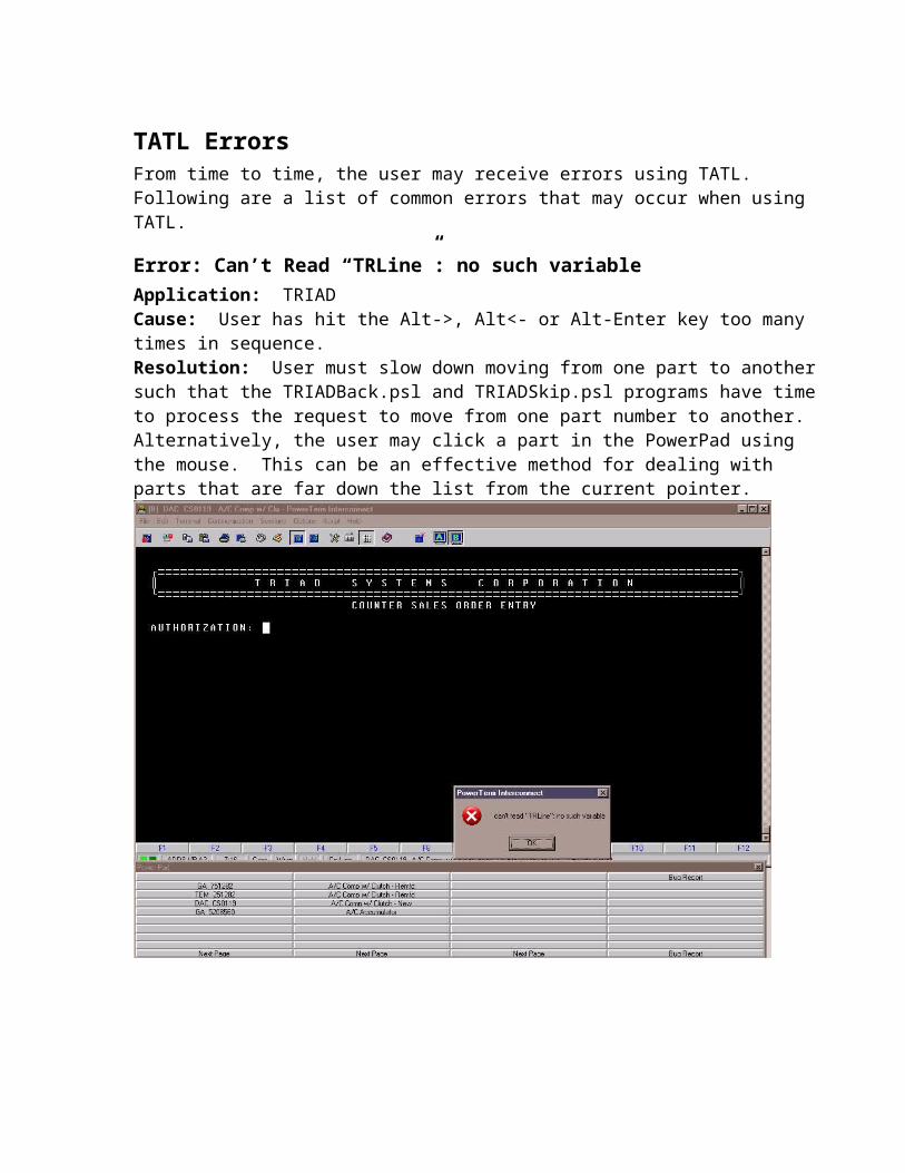
Click here for options”. Click the message and select Download File. You will likely need to reenter the password fields.
4. Click the Save button and in the Filename field, specify the location for the current backup: \\192.168.0.248\Documentation\FirewallConfigurations\Archive\sitename.sgc. E.g. xxxxxx.sgc.
5. When prompted to close or open, click the Close button.
Network Grooming – Firewall Configuration – Remote Firewall VPN AccessTo log into the remote firewall, we have established a security procedure that relies on VPN access. Each firewall should be configured with the following VPN access:
1. On remote firewall, click PPTP VPN Server.2. Click the Enable PPTP Server checkbox.3. Enter 192.168.xx.15-19 in the IP Address to Assign to VPN Clients
field.4. Click the MSCHAPv2 and Encryption radio button under
Authentication Scheme.5. Click the Local radio button under Authentication Database.6. Click the Continue button.7. Enter XYZadmin in the Add New Account - Username field.8. Enter xxxxxx in the Password field. 9. Click the Add button.
You must test your connection to ensure that it works. Note that you should just check it long enough to see if connection is established and then disconnect the connection since you Internet will be disengaged while the VPN is up. See procedures:
Connecting to a Remote Firewall - From Sites Other than XYZ HQ LAN
Network Grooming – Firewall Configuration – Remote MTUIn order for some applications such as remote desktop connection to function properly, the Maximum Transmission Unit (MTU) or size of packets must be set.
1. On remote firewall, click IPSec.2. Click the Set the IPSec MTU to be checkbox and enter a value of 1300 in
the field.3. Click the Apply button to apply the changes.
Network Grooming – Firewall Configuration – Verify Remote IPSec SetupFor the VPN to establish correctly, the tunnel should be configured with a specific configuration. Verify the correct remote firewall configuration using the following procedures:
1. On local firewall (http://192.168.xx.2), click IPSec.2. Click the appropriate tunnel name.3. Verify the following on the initial screen:
Enable this tunnel is checkedTunnel is to go out default gateway interfaceThis tunnel will be using Aggressive mode Auto Key (IKE)The remote party has Static IP Address Authentication Used Preshared secred

The local party is a single network behind this cyberguardThe remote network is a single network behind a gatewayThis tunnel is to be a route to a remote partyClick the Continue button.
4. Verify the following on the screen:Initiate the tunnel from this end checkedRequired Endpoint ID host@city## (e.g. Charleston3)Enable IP Payload Compression uncheckedEnable dead peer detection checkedDelay 9Timeout 30Enable Phase 1&2 rekeying to be initiated uncheckedClick the Continue button.
5. Verify the following on the screen:Remote parties IP address xx.xx.xx.xxOptional Endpoint ID host@city## (e.g. Charleston3)Click the Continue button.
6. Verify the following on the screen:Key lifetime 60Rekey margin 10Rekey Fuzz 100Preshared secret xxxxxxx (where xx is store number)Phase 1 Proposal 3DES-SHA-Diffie Hellman Group 2 (1024 bit)Click the Continue button.
7. Verify the following on the screen:Key lifetime 60Phase 2 Proposal 3DES-SHA-Diffie Hellman Group 2 (1024 bit)Local network 192.168.xx.0/255.255.255.0 (xx is store IP)Remote network 192.168.0.0/255.255.255.0Click the Apply button.
8. The tunnel will restart.
Network Grooming – Firewall Configuration – Verify Local IPSec SetupFor the VPN to establish correctly, the tunnel should be configured with a specific configuration. Verify the correct configuration using the following procedures:
9. On local firewall (http://192.168.0.2), click IPSec.10. Click the appropriate tunnel name.11. Verify the following on the initial screen:
Enable this tunnel is checkedTunnel is to go out default gateway interfaceThis tunnel will be using Aggressive mode Auto Key (IKE)The remote party has Static IP Address (If static IP is deployed)Authentication Used Preshared secredThe local party is a single network behind this cyberguardThe remote network is a single network behind a gatewayThis tunnel is to be a route to a remote party

Click the Continue button.12. Verify the following on the screen:
Optional Endpoint ID host@city## (e.g. Charleston3)Enable IP Payload Compression uncheckedEnable Phase 1&2 rekeying to be initiated uncheckedClick the Continue button.
13. Verify the following on the screen:Required Endpoint ID host@city## (e.g. Charleston3)Click the Continue button.
14. Verify the following on the screen:Key lifetime 60Rekey margin 10Rekey Fuzz 100Preshared secret xxxxxxxx (where xx is store number)Phase 1 Proposal 3DES-SHA-Diffie Hellman Group 2 (1024 bit)Click the Continue button.
15. Verify the following on the screen:Key lifetime 60Phase 2 Proposal 3DES-SHA-Diffie Hellman Group 2 (1024 bit)Local network 192.168.0.0/255.255.255.0Remote network 192.168.xx.0/255.255.255.0 (xx is store IP)Click the Apply button.
16. The tunnel will restart.
Network Grooming – Firewall Configuration – Time ServerIn order for the firewall to have an accurate time for the log file, it should request correct time from a time server. Set up the time server using the following procedures:
1. On remote firewall, click Date and Time.2. Check the Set Time checkbox.3. Check the Local NTP Time Server checkbox.4. Enter time-a.nist.gov in the Remote NTP Server field under NTP Time
Server. 5. Click the Apply button below the section for the NTP Time Server
section of the screen.6. Verify the Region is US and the Location is Central. 7. Click the Apply button if changed in the Locality section of the screen.8. If time at the top does not change, click the first Set Date and Time
button at the top of the page.9. Verify the time is accurate.
Network Grooming – Firewall Configuration – DHCP ServerThe DHCP server must be assigned for installation of the Smart Terminals and other devices that may need an IP address assignment. The Smart Terminals will be installed with dynamic IP address assignment prior to receiving their static IP address assignment.
1. On remote firewall, click DHCP Server>Edit Server or Add Server if not added.

2. Click the Add Server button (if this button is not listed, then the DHCP server is already on.)
3. Skip to the Initial Dynamic IP Address Range field and enter 192.168.xx.50-75.
4. Check Enable DHCP Server for this Subnet checkbox.5. Enter 192.168.xx.100 in the Gateway Address field where xx matches the
3rd octet of the router LAN IP address.6. Enter the Primary (router address 192.168.xx.100) and Alternate
(151.164.14.201) DNS server addresses in the format as follows (separated by commas):
Example: 192.168.xx.100, 151.164.14.2017. Click the Apply button.
Network Grooming – Firewall Configuration – Access (Internet Allow) List1. Open Internet Explorer on a computer attached to the XYZ
192.168.0.x network.2. In the address line, enter the address of the firewall you wish to
configure. In nearly every instance, the firewall address will be http://192.168.xx.100 where xx is the store indicator.
3. Click Firewall>Access Control.4. You will be prompted for the login. Log into the firewall router using
root/xxxxxxx.5. Under the Main option, check the Enabled and Block by Default
checkboxes.6. Click the Apply button.7. Click the IP Lists option at the top of the screen.8. The screen is divided into 6 quadrants. In the Source>Allow list
quadrant, enter192.168.0.1-255131.107.1.10
9. In the Source>Destination list quadrant, enter192.168.0.1-255.131.107.1.10
10. Click the Apply button.11. Click the Web Lists option at the top of the screen.12. The screen is divided into 2 halves. In the Allow List quadrant, add
the following items to the list: snapgear.com (Firewall prior configuration)cyberguard.com (Firewall prior configuration)zonelabs.com (Firewall prior configuration)nist.gov (Firewall prior configuration)napaprolink.com (for NAPA parts viewing)dupont.com (for paint formulas)genpt.com (for NAPA Prolink Images)keir.net (for time server)nist.gov (for time server)

13. Click the Apply button.14. Click the Content option at the top of the screen.15. Uncheck the Enable Cache checkbox.16. Scroll down to the bottom of the screen and click the Apply button.

Network Grooming – Firewall Configuration - DNSDNS Servers are the white pages of the Internet. The DNS server provides the lookup for translation of a name like napaprolink.com to an IP address or essentially and Internet telephone number. The following strategy should be employed throughout XYZ’s network to ensure availability of Internet resources requiring DNS server lookup:
Note: This step will reset the firewall. In some cases (if there is no Smart Terminal deployed), the IPSec tunnel may not reestablish.
Note: Skip this step for PPPoE and Cable Modem Internet Generic (DHCP) sites.
1. On remote firewall, click Network Setup.2. On the Port Name - Internet, if the letters PPPoE appear in the combo
box, you are finished with the Network Grooming – Firewall Configuration - DNS procedure. If you do not see the letters PPPoE, continue with the next step.
3. Click the Port Name – Internet pull down list and select Edit Current Settings.
4. In the DNS Servers field, enter the primary and secondary DNS servers separated by a comma:
xx.xx.xx.xx, 151.164.14.201(where xx.xx.xx.xx is pulled from the following table based on the ISP for your site. )
5. Click the Apply button.
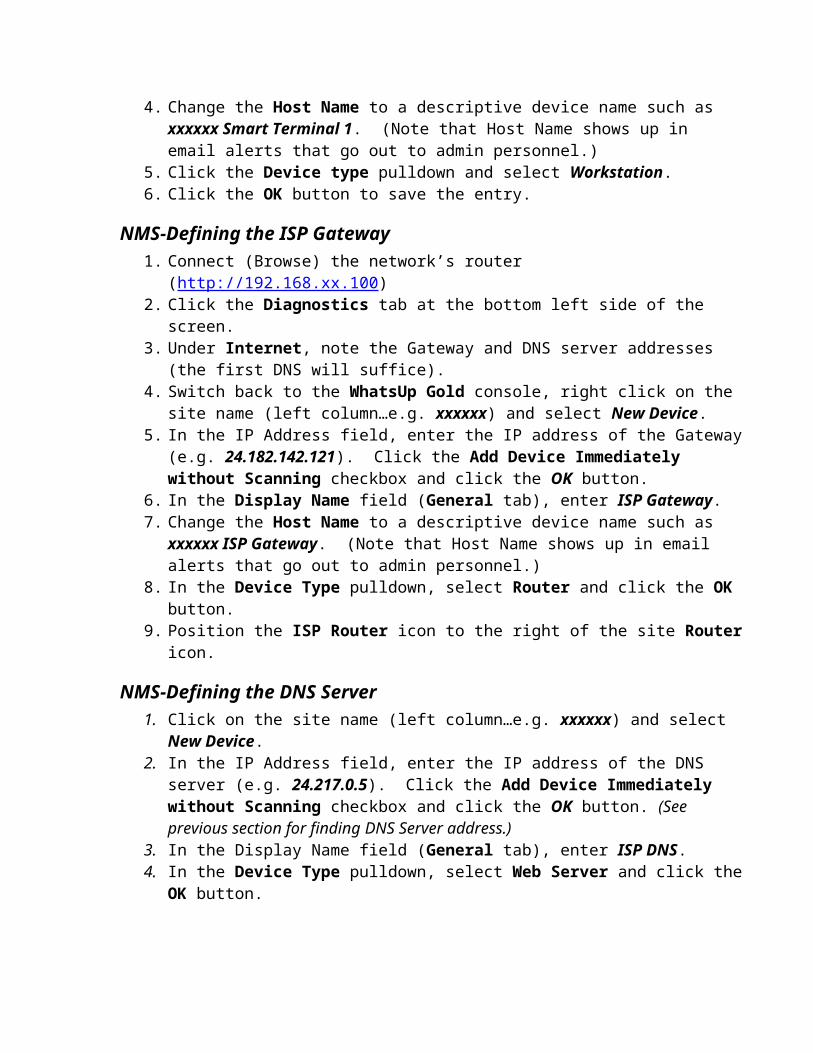
Network Grooming – Firewall Configuration – Disable Internet AccessThe original configuration of the remote firewalls allowed for Internet access direct to the management console. To enhance security, we now require PPTP VPN access to the management console set up in a previous step. This step disables open Internet access to the management console.
1. On remote firewall, click Incoming Access. Uncheck Internet Interface Telnet and Web (Http).
2. Uncheck the checkbox for Internet Interface – Web (HTTP). 3. Click the Apply button to apply the changes.
Network Grooming – Firewall Configuration – Firmware Upgrade
NOTE: This step is a potentially a major disruption and should be done after hours.
To upgrade the firmware on the firewall, it is best to do it from a local LAN server. The upgrade process uses a TFTP process which lacks sufficient error control to perform over the Internet. The documentation on the firewall specifically states that abnormal termination during the upgrade process can necessitate shipping the unit back to the factory for restoration.
1. Connect to a smart terminal at the site where the firewall is to be upgraded and log in as Administrator. Smart Terminal – Forcing Prompt for Administrator Logon
2. Ensure Enable the Write Filter (Green light) is on…we do not want changes saved to the terminal.
Note: You do not need to load the TFTP server after version 3.1.4 since this version allows direct upgrade from the connecting computer.
3. Install the TFTP program by clicking Start > Run > \\192.168.0.248\documentation\FirewallFirmware\TFTPServer\SolarWinds-TFTP-Server.exe (Wait 5 minutes minimum for program to load…Click Run…Next…Next…etc…use all program defaults).
4. After Solarwinds TFTP Server is installed, then proceed to the next step.5. Click Start>Programs>SolarWinds Free Tools>TFTP Server. 6. When the program opens, click File>Configure.7. Click the Security tab.8. Select the Transmit and Receive Files radio button.9. Click the OK button to save the change.10. Click Start > Run > \\192.168.0.248\documentation\FirewallFirmware\
and click the OK button.11. Open the folder for the firmware desired. For remote SG300’s, the current
folder at the time of this writing is SG300V3.1.4u5. 12. In the folder selected, highlight the firmware binary file ending in sgu. 13. Click Edit > Copy to Folder.14. Copy file to the folder c:\TFTP-Root\.15. Log into the firewall (Browse to 192.168.xx.100) at the remote site and
click the Advanced>Flash Upgrade>Flash Upgrade via tftp option.

16. Enter 192.168.xx.15y in the IP Address field (the address of the Smart Terminal you are using as the TFTP Server) and enter the name of the firmware file you are upgrading (e.g. SG300_v3.1.4u5_20070228.sgu) and click the Upgrade button.
17. You should receive a message that the firmware looks OK and that the firewall will perform the upgrade.
18. It will take several minutes for the upgrade to complete. Once the upgrade is complete, the firewall will restart. You can set up a persistent ping to monitor when the firewall finally restarts by issuing the command Start>Run>CMD>ping 192.168.xx.100 –t.
19. Verify the messages after the firewall update. You may need to validate changes from the old version to the new version.
Note: You do not need to load the TFTP server after version 3.1.4 since this version allows direct upgrade from the connecting computer.
Network Grooming – Firewall Configuration – Dealing with Upgrade IssuesAfter the firewall is upgraded, some features must be reconfigured since they are handled differently in the upgraded version of the firmware. You must acknowledge that you understand this.
1. Connect to the remote firewall and click Advanced.2. You will receive a message at the top of the screen:
Until you go to the Firmware Upgraded page to resolve this situation no configuration changes will be saved.
3. Click the Firmware Upgraded link.4. Scroll to the bottom of the screen and click the Continue Configuring
button.5. Notice the Action Successful message at the top of the screen.
Network Grooming – Firewall Configuration – ACL Reconfiguration after UpgradeAfter the firewall is upgraded, some features must be reconfigured since they are handled differently in the upgraded version of the firmware. The biggest change is in the Access Control Lists which are used to restrict user access to Internet web sites. By default after the firmware upgrade, the ACL will be disabled, thus allowing all traffic to flow. To configure the ACL to restrict access, employ the following steps:
1. Connect to the firewall and click Firewall>Definitions>Addresses.2. Click the New button.3. Enter XYZ in the Name field and 192.168.0.1-254 in the IP Address field.4. Click the Finish button.5. Click the New button.6. Enter Terminal Time in the Name field and 131.107.1.10 in the IP
Address field.7. Click the Finish button.

8. To the right of the New button, click the pull down list and select Address Group.
9. Enter OK IP Addresses in the Name field and check the checkboxes the entries for both XYZ and Terminal Time.
10. Click the Finish button.11. Click Firewall>Access Control>Main.12. Click the Enable Access Control checkbox.13. Change the Default Action field to Block.14. Click the Submit button.15. Click Firewall>Access Control>ACL.16. Click the Allow Source Host pull down list and select OK IP Addresses.17. Click the Allow Destination Host pull down list and select OK IP
Addresses.18. Click the Submit button.19. Verify in WhatsupGold that the site’s terminals are active.
Network Grooming – Firewall Configuration – Reset Smart Terminal to User ModeWhen changes are made to the Firewall Configuration, reset the terminal to User Mode.
1. Connect to the Smart Terminal used for the TFTP Server.2. Click Start>Shutdown>Logoff Administrator.3. You may wish to bring up Triad and TAMS for the user.
Network Grooming – Firewall Configuration – Configuration Backup After UpgradeWhen changes are made to the Firewall Configuration, a backup should be completed.
4. Move the existing backup file from \\192.168.0.248\Documentation\FirewallConfigurations to \\192.168.0.248\Documentation\FirewallConfigurations\Archive
5. On remote firewall, click System>Backup/Restore>Remote Backup/Restore>Save Configuration.
6. Enter firewall password (xxxxxxx) in Password and Confirm Password fields and click the Submit button.
7. You may receive a message “To protect your security, Internet Explorer blocked this site from downloading files to your computer. Click here for options”. Click the message and select Download File. You will likely need to reenter the password fields.
8. Click the Save button and in the Filename field, specify the location for the current backup: \\192.168.0.248\Documentation\FirewallConfigurations\sitename.sgc. E.g. xxxxxx.sgc.
9. When prompted to close or open, click the Close button.
Network Grooming – Firewall Configuration – Configuration Restore After UpgradeWhen changes are made to the Firewall Configuration, a backup should be completed.

1. On remote firewall, click System>Backup/Restore>Remote Backup/Restore>Restore Configuration.
2. Click the Browse button and select the file from the backup folder \\192.168.0.248\Documentation\FirewallConfigurations.
3. Enter firewall password (xxxxxxx) in Password field and click the Submit button.

Offsite BackupsThe WDM system (192.168.0.248) is a repository for information about XYZ. The WDM system houses the following critical operational information:
Wyse Device Manager configuration and tracking system for Smart TerminalsWhatsUp Gold network management systemXYZ IntranetXYZ Operations Documentation
We have set up RemoteDataBackups.com for off-site storage backup of this information.
Offsite Backups – Setup InformationThe remotedatabackups.com site requires an encryption key that is not kept by anyone except the customer. XYZ must retain this encryption key since staff personnel at the service provider will not know what it is.
RemoteDataBackups.com Account#: 11479-14560RemoteDataBackups.com Encryption Key: xxxxxxxPayment Information: Annually on 7/25 (started 2007) on Bob Tlapek’s Company Credit Card ending in 2299 Exp Date 10/11 for approximately $360/year.
Offsite Backups - Manually Running BackupsThe RemoteDataBackups.com utility will run automatically weekly and will keep 10 generations of files. If you have made major changes and you feel you need to run a backup immediately, perform the following procedures:
1. Click Start>Programs>Remote Data Backups>Remote Data Backups.2. Click the Backup Now button.3. The utility will back up the files defined for backup. View the files to ensure the data
you wish to back up is in the list by clicking Backup View.
Offsite Backups - Verifying Files Backed UpYou may wish to verify from time to time which files are automatically backed up.
1. Click Start>Programs>Remote Data Backups>Remote Data Backups.2. Click the Backup tab.3. Click Explore to Pick Files (on the right side of the screen).4. Checkboxes will denote the folders that are backed up. Currently, the following
folders are backed up in the system:C:\BugReport\ (contains problem log)C:\ChangeLog\ (contains change log)C:\Inetpub\ (contains http://XYZ Intranet web site)C:\Rapport Packages\ (contains WDM Package updates)

C:\TATL\ (contains all documentation, WDM backups, WhatsUpGold backups and Powerterm8.2 installation files)
Offsite Backups - Verifying Backups Run SuccessfullyYou may wish to verify from time to time that backups are running successfully.
1. Click Start>Programs>Remote Data Backups>Remote Data Backups.2. Click the Log tab.3. Review the list to see the dates of recent backups. This list will show both
automatically scheduled backups as well as manually initiated backups.4. Click the View Details button to see exactly which files were backed up during each
session.
Offsite Backups – Restoring FilesIn order to restore files to a new computer, you must have the account number and encryption key. RemoteDataBackups.com Account#: 11479-14560RemoteDataBackups.com Encryption Key: xxxxxxx
1. Install remotedatabackups.com 10GB service using the account# and encryption key.2. Click Start>Programs>Remote Data Backups>Remote Data Backups.3. Click the Retrieve View tab.4. If you wish to retrieve the most recent file backed up, then simply find the file or
folder in the Retrieve View listing and click the Retrieve Now button. If you wish to retrieve a file older than the last generation, click the Retrieve Options button and click the Show All Versions radio button to view generations of a file.
Connecting to XYZ from Public Internet via Remote Access VPNYou can remotely connect to the XYZ network from the public Internet by establishing a VPN tunnel from your computer to the Internet. By connecting remotely to the XYZ network, you can access the following items from anywhere on the Internet:
Wyse Device ManagerWhat’s Up GoldTAMSTriad (although this is publicly available without protection currently)Remote terminal servers (on AT&T connection)Local HQ and Remote routers (remote router access requires AT&T connection)Any PC or Smart Terminal on the XYZ network (remote Smart Terminals require AT&T
connection)
VPN to : Access to HQ Only
Access to All Stores
IP Address General UserID
Big River Yes xx.xx.xx.xx backupatt/XYZ070709AT&T Yes xx.xx.xx.xx Must Define

Setting Up Remote Access VPN Username and Password on the Firewall/RouterYou will first need to set up a username and password on either the AT&T or Big River router. This username and password will be used to authenticate the remote PC connecting to the router. The username and password will be entered at the local firewall/router as well as the remote computer.
Local Router
Local IP Address
Administrator Login
Big River http://192.168.0.3 root/xxxxxxAT&T http://192.168.0.2 root/xxxxxx
1. Connect to the router using the link/URL above.2. Click the PPTP VPN Server option on the left side of the screen. (Enter
username/password option above when prompted.)3. Click the Authentication Database>PPTP Accounts option.4. Under Add New Account, enter Username and Password (twice), but leave the
Windows Domain field blank and click the Add button.
Setting Up and Connecting VPN Client on the Remote PCYou must now set up a VPN client on the remote computer. This procedure assumes Windows XP, but may be adapted for Vista or Windows 2000.
1. Click Start>(Settings)>Control Panel>Network Connections.2. Click the Create New Connection option (then Next button).3. Select the option Connect to the network at my workplace (then Next button).4. Select the option Virtual Private Network connection (then Next button).5. Enter XYZ AT&T or XYZ Big River for Company Name (then Next button).6. Assuming your Internet is provided using DSL or Cable Internet, select Do not dial the
initial connection option (then Next button).7. Enter the IP address from the table below for the router to which you desire to connect
(then Next button. You may desire to select the checkbox option to Add a shortcut to this connection to the desktop, then the Finish button).VPN to : Access to
HQ OnlyAccess to All Stores
IP Address General UserID
Big River Yes xx.xx.xx.xx backupatt/XYZ070709AT&T Yes xx.xx.xx.xx Must Define
8. You will be prompted with a screen prompting the username and password. Enter the username and password defined for your connection and click the checkbox option Save this user name and password for the following users to have Windows “remember” your login information.
9. Click the Connect button to connect to the XYZ network. You will receive a message indicating whether the connection was successful or not.

10. When you are finished using the VPN tunnel connection, to disconnect from the XYZ network, right click the double computer icon in the lower right hand corner of the screen (holding the cursor over it will display a message indicating whether the network icon is the one designated for the VPN connection). Select the Disconnect option.
Printing Configurations and IssuesXYZ has several issues relating to the existing printing configuration:
When connectivity is lost to the site, XYZ must reset printers and terminal servers too often to restore working printers.
When in backup mode over the Big River VPN, there is currently no printing function.
Terminal Servers are a problem in general and represent possibly needless cost and excessive failure points for printing.
Printing is slow…about half the speed of parallel port printing, but Serial port on Printer is limited to 9600bps.
Current Printer ConfigurationCurrent configuration for printing consists of the following:
Okidata Microline 320 printer configured to emulate an IBM PPR or ProPrinter II. Serial connection to Systech terminal Server port 4. Communications configuration 8N1 9600 Xon/Xoff. Printer must be specifically defined in Triad for every port connection.
Desired Printer ConfigurationDesired printing configuration would eliminate the Systech Terminal Server completely. The following configuration is being explored:
Using the Smart Terminal built-in print server (Windows XP). Direct Printing from the HP Triad system for Windows printing support.
Triad has a product called Ultiforms that provides Windows printing support and costs around $15k to $20k.
We may be able to get printing support to terminals direct using Unix print services. According to Wyse, we load the IPPrinting add on to the smart terminals to add the LPR/LPD print services to the smart terminals.
Once we have this added, printing to the smart terminals should look just like printing to the terminal servers.
We must define the IP printing configuration via the smart terminals in the Triad system much like the terminal servers are today.
We must then configure static IP addresses for Big River VPN and define dual ports for each terminal.
Then we must assign the backup terminal its own printer definition.
Printer Configuration Update ProcedureIn order to use the Smart Terminal as a replacement for the Terminal Server, the following configuration steps should be used:

Update each Smart Terminal with the IPPrinting add-on. (This is only required for the terminal that will actually connect to the Printer, but for backup purposes, it will be nice to have all Smart Terminals defined with the capability. To replace a failed Smart Terminal Print Server, the site need only physically replace/move the Smart Terminal and change the IP address of the Smart Terminal to match the previous Smart Terminal Print Server.)
Define the printer to each Smart Terminal (Again, for the migration, only required for the Smart Terminal Print Server.) This will likely be done through a WDM update.
RECOMMENDATION: Make the Smart Terminal Print Server always be IP address 192.168.xx.150.110?
Move the printer from the terminal server to the Com1 serial port (101010 1) on the Smart Terminal Print Server.
In Triad, change the IP address of the IP printing to point to the new Smart Terminal Print Server.
In order to make the
The following code should work for Samba interface on HP-UX#!/bin/sh# Print from Unix on a printer on SMB network. An assumpbiont is that # 'Printer' was posted as a passwordless "share"#client="myclient" # client name here...pshare="printer" # and here printer share nameprintfile="\tmp\smbspool.$$"
cat > $printfileif [ -s $printfile ] ; then ( echo "translate" ; echo "print $printfile" ; echo "quit" ) \ | smbclient \\\\$client\\$pshare -P -Nfirm -f $printfileexit 0
Looming Deployment Issues Project Summary ListRemote Firewall Access List Updates
Remote Firewall Access List Updates Currently XYZ has limited capabilities for changing remote firewalls. With the introduction of Internet capability at the stores, XYZ will receive requests for updates to the “Allow List” for Internet sites. The current process for handling these updates is as follows:
1. Store #1 issues request for site xyz to be added to the “Allow” list.2. Manual configuration of Store #1.3. Testing Store#1 to ensure “Allow” list is operational.4. Store #2 issues request for site xyz to be added to the “Allow” list.5. Manual configuration of Store #2.6. Testing Store#2 to ensure “Allow” list is operational.7. Repeat for each store request.
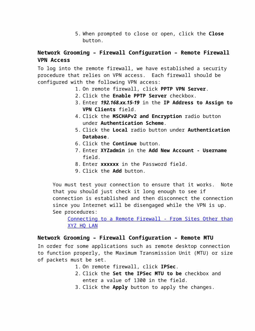
If XYZ resolves the issues relating to the VPN tunnels, the following process might be followed:1. Reimage the Smart Terminal over the XYZ VPN network2. Reconfigured for that store network
Remote Firewall Access List Updates Issue Resolution and CostThe problem of excessive time spent on firewall updates can be resolved through the deployment of the Secure Computing firewall management system.
1. Research2. Software Product Purchase 3. Hardware deployment requires Linux based management system.4. Either documentation development and project handoff or full project deployment
Estimated Cost: SecureComputing Command Center SW $6600With SW & Support and 1 year updates
SW Annual Support and Updates (Year 2) $1100Hardware (Linux PC) $2000Installation by GCC Certified Pro $8000 Total Project Costs $16,600

XYZ System and Network DiagramsThe following network diagrams illustrate the XYZ networks and system currently in place.
HQ Warehouse Configuration (1 of 2)
HQ Warehouse Configuration (2 of 2)//** Diagram removed for security purposes. **//
Triad-Atlanta Connection
WEJOEI and Electronic Cataloging (Old) Function//** Diagram removed for security purposes. **//
Typical Store Configuration (Old)//** Diagram removed for security purposes. **//
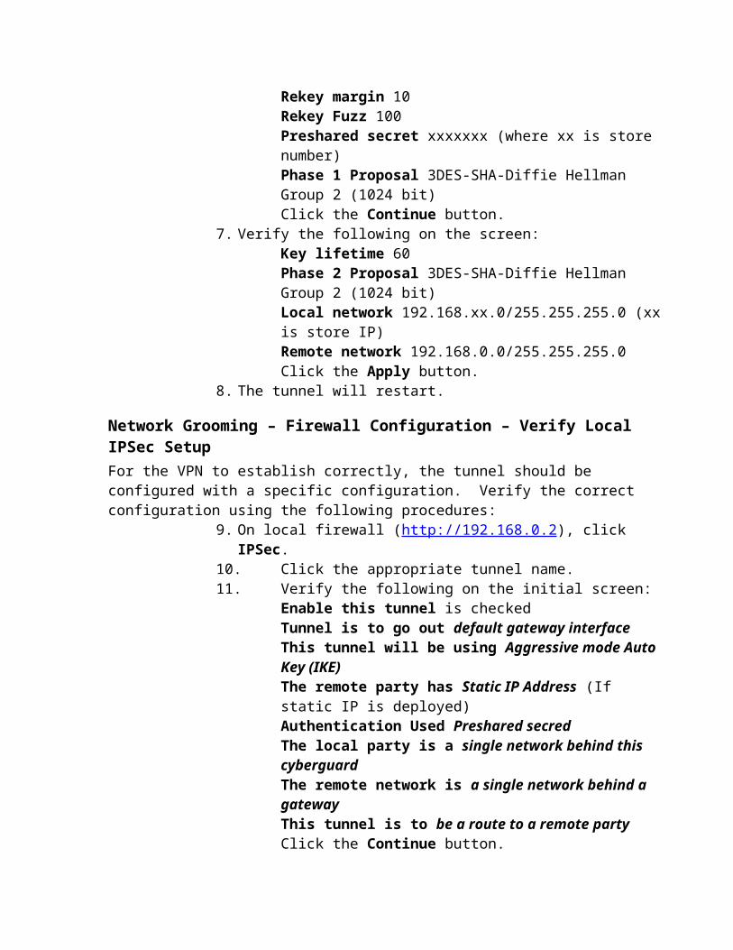
Typical Store Configuration - Smart Terminal//** Diagram removed for security purposes. **//
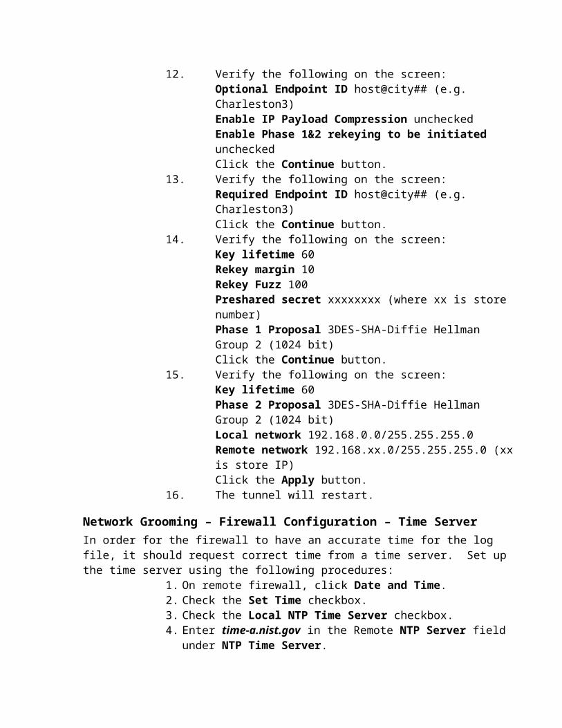
TATL Keyboard OverlayThe next pages may be printed and cut out for a keyboard overlay.
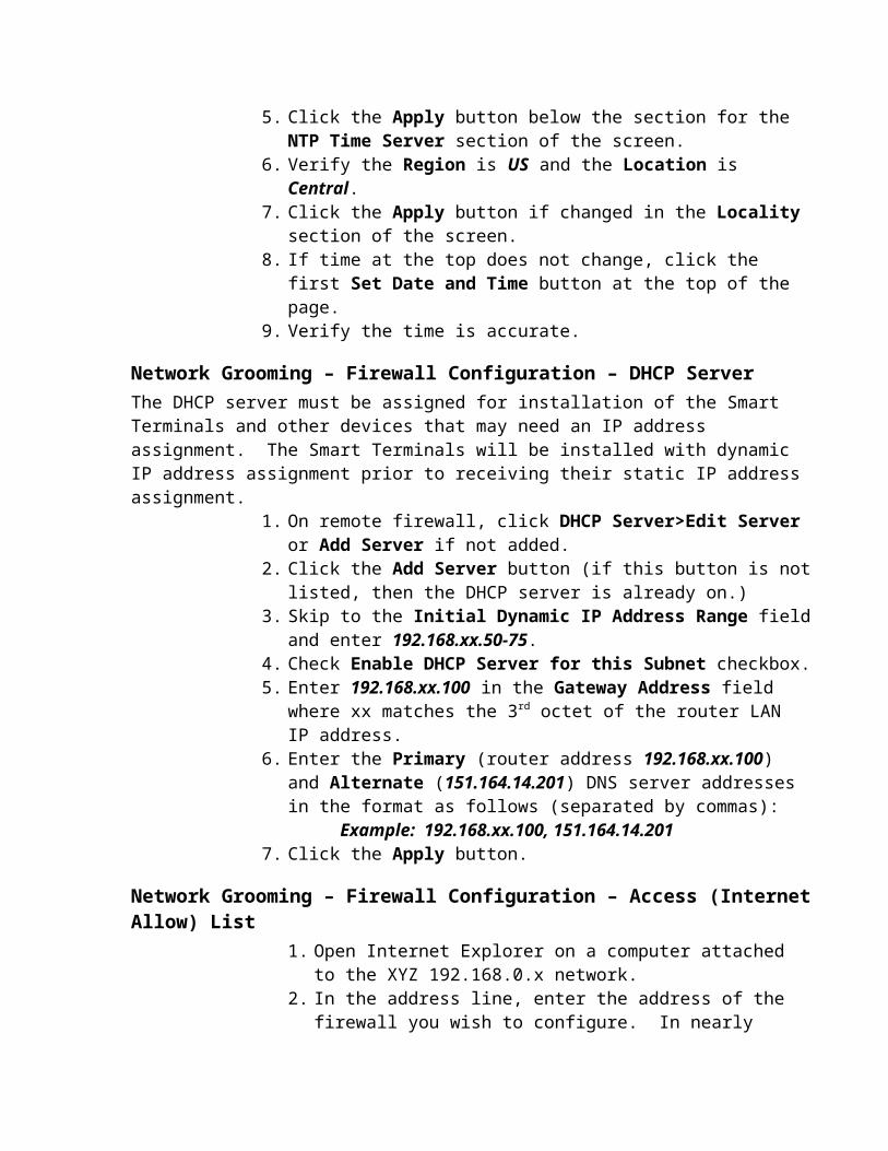
Systech Terminal Server NotesDefault IP address is 0.0.0.0.Default user password is user.Default administrator password is admin.
To log in as administrator:
Welcome to the port server Remote Communications ServerPassword: user>>adminPassword: adminAdmin>>

Change Log
The following changes have been made to this document:6/6/2007 – Added Change Log to document.6/6/2007 – Added Hyperlinks for various functions in the document for quicker access.6/6/2007 – Added to Smart Terminal Install procedures for static IP.6/6/2007 – Added to Smart Terminal Install procedures for Screen Layout.6/6/2007 – Added to Smart Terminal Install procedures for Setting the Time Zone.6/6/2007 – Added procedures for firewall setup of Allow List and DHCP Server.6/6/2007 – Added TRIAD procedures for adding Smart Terminal IP address to host table.6/6/2007 – Added TRIAD procedures for assigning license port to Smart Terminal IP Address. 6/6/2007 – Added Smart Terminal procedures for DuPont Coatings icon on desktop.6/6/2007 – Added Smart Terminal procedures for correcting problem with TRIAD screen sizing.6/6/2007 – Added procedure for firewall change to caching on access list for PartsPro.6/10/2007 – Added procedure for genpt.com to access control allow list on firewall.6/10/2007 - Added procedure for 131.107.1.10 to access control allow list on firewall for time
synch.6/10/2007 - Added procedure for nist.gov and keir.com to access control allow list on firewall
for time synch.6/12/2007 – Added notes for NMS (WhatsUp Gold) installation. 6/12/2007 – Added procedures for adding devices to NMS (WhatsUp Gold).6/12/2007 – Added procedures for adding cell phone email notification for network outages.6/12/2007 – Added procedures for diagnosing problems with devices based on color in NMS.6/26/2007 – Added procedures for Smart Terminal Updates and Change Log management.7/10/2007 – Added procedures for Backup VPN Setup on remote desktop for connection over
Big River DSL Line.7/10/2007 – Added procedures for Establishing Backup Connection over Big River DSL line.7/10/2007 – Added procedures for Firewall Configuration – Firmware Upgrade7/10/2007 – Added procedures for Firewall Configuration – Remote Firewall DNS
Configuration.7/10/2007 – Added procedures for Firewall Configuration – Remote Firewall VPN Access7/10/2007 – Added procedures for Firewall Configuration – Time Server Configuration.7/10/2007 – Added procedures for Firewall Configuration – Remote MTU Configuration.7/10/2007 – Added procedures for connection for Connecting to a Remote Firewall
From the XYZ HQ LANFrom a Location Other than XYZ HQ LAN
7/10/2007 – Modified procedures for Smart Terminal Initial Configuration at XYZ for Installer Handoff
7/10/2007 – Added procedures for Smart for Network Grooming – Firewall Configuration – Disable Internet Access
7/10/2007 – Added procedures for Network Grooming – Firewall Configuration – Configuration Backup
7/10/2007 – Added procedures for Network Grooming – Firewall Configuration – Configuration Restore
7/11/2007 – Revised procedures for Smart Terminal Setup.

7/11/2007 - Added procedures for WDM – Deleting Smart Terminals from the WDM Device Manager List.
7/11/2007 - Added procedures for Network Grooming – Firewall Configuration – ACL Reconfiguration
7/12/2007 - Added procedures for Network Grooming – Firewall Configuration – Configuration Backup After Grooming.
7/12/2007 – Modified procedures for restoring backup after grooming.7/12/2007 - Added procedures for NMS-Adding Devices Manually.7/12/2007 - Added procedures for Smart Terminal Configuration - Installation at Remote Site.7/12/2007 - Added procedures for Smart Terminal Configuration – After Installation at Remote
Site.7/16/2007 – Revised procedures for DNS primary server.7/16/2007 – Revised order of grooming to reduce outages and streamline process flow.7/16/2007 - Added procedures for Network Grooming – Firewall Configuration – Verify Local
IPSec Setup7/16/2007 - Added procedures for Network Grooming – Firewall Configuration – Verify Remote
IPSec Setup7/16/2007 - Added procedures for Network Grooming – Firewall Configuration – Dealing with
Upgrade Issues7/18/2007 – Modified procedures for WDM – Backing up the WDM Database. 7/18/2007 – Added procedures for Offsite Backups – Setup Information.7/18/2007 – Added procedures for Offsite Backups - Manually Running Backups.7/18/2007 – Added procedures for Offsite Backups - Verifying Files Backed Up.7/18/2007 – Added procedures for Offsite Backups – Restoring Files.7/18/2007 – Added procedures for Offsite Backups - Verifying Backups Run Successfully.7/24/2007 – Modified procedures for handling WDM errors on updates.7/24/2007 – Modified procedures for Off-Site Backups to include payment history and upcoming
payment information.8/2/2007 – Added procedures for Connecting to XYZ from Public Internet via Remote Access
VPN.8/2/2007 – Added procedures for Setting Up Remote Access VPN Username and Password on
the Firewall/Router.8/2/2007 – Added procedures for Setting Up VPN Client on the Remote PC.8/2/2007 – Updated Network Diagram Visio images to reflect recent changes (new TAMS,
etc…)8/2/2007 - Updated procedures for Grooming based on walk-through with Susan.


