NZTA P32: 2011 SP/SP32: 2011 110607 P32 SPECIFICATION FOR ELECTRONIC WARNING SIGNS ON STATE HIGHWAYS Page 1 of 29 P32 SPECIFICATION FOR ELECTRONIC WARNING SIGNS ON STATE HIGHWAYS 16 March 2011
Transcript
NZTA P32: 2011
SP/SP32: 2011 110607 P32 SPECIFICATION FOR ELECTRONIC WARNING SIGNS ON
STATE HIGHWAYS
Page 1 of 29
P32 SPECIFICATION FOR ELECTRONIC WARNING SIGNS ON STATE HIGHWAYS
16 March 2011
NZTA P32: 2011
SP/SP32: 2011 110607 P32 SPECIFICATION FOR ELECTRONIC WARNING SIGNS ON
STATE HIGHWAYS
Page 2 of 29
Document No: P32 Document Date: Organisation
16 March 2011
Report Status: Final NZTA Reference No: P32
Title & Subtitle: Author(s): NZ Transport Agency Specification for Electronic Warning Signs on State Highways
This document is the NZ Transport Agency Specification for Electronic Warning Signs. A separate document titled NZTA Notes for Electronic Warning Signs is available to assist the initial concept processes, site selection, support structure & foundation construction, and structures inspection & maintenance.
Document Purpose
The purpose of this document is provide a set of specifications for the design and procurement of electronic warning signs (EWS), for the State Highway network where NZ Transport Agency has an objective of encouraging safe driver behaviour. The specifications for EWS found in this document including references to communications and external standards are to be regarded as mandatory when any part of this document is referenced as part of any related procurement process.
It is mandatory that these documents be issued in their entirety as part of any EWS purchase process. Key Words: Published by:
NZ Transport Agency Private Bag 6995 Wellington 6141
4. ...............................................21 Data Capture and Download, Remote Diagnostics4.1 ............................................................................21 Data Capture and Download4.2 .........................................................................................22 Remote Diagnostics
6. .....................................24 Support Structure and Foundation Design Requirements6.1 ...................................................24 Standard Support Structure and Foundations6.2 ................................................................................25 Foundation Requirements6.3 ...........................................................................26 Applicable Design Standards
8. .....................................................................27 Testing and Commissioning of EWS8.1 ....................................................................27 Factory Acceptance Testing (FAT)8.2 ..........................................................................27 Site Acceptance Testing (SAT)8.3 ...............................................................................................27 Commissioning8.4 ........................................................................................27 Traffic Management
9. .....................................................................28 Warranties and Maintenance Period9.1 ...........................................................................................28 Standard Warranty9.2 .........................................................................................28 Maintenance Period
10. ...........................................28 Post Commissioning Documentation and Spare Parts10.1 ............................................................................................28 As Built Drawings10.2 .................................................28 Operating Servicing and Maintenance Manuals10.3 ......................................................................................................29 Spare Parts
List of Tables Table 1: Definitions and Acronyms .......................................................................................5
NZTA P32: 2011
SP/SP32: 2011 110607 P32 SPECIFICATION FOR ELECTRONIC WARNING SIGNS ON
STATE HIGHWAYS
Page 4 of 29
1. Introduction
1.1 Scope
This Specification outlines requirements for a range of electronic warning signs (EWS). That is those warning signs that have an electronic display component which becomes active when the hazard or activity described by the sign is likely to be occurring on or close to the roadway. Examples of EWS provided in this Specification include: Speed Indication Device, Curve Warning, Cycle Warning, Rural School, and Slippery Surface Warning. These examples are representative but not exclusive. Any new signs, or a different layout of a sign illustrated in this Specification, must have their words/fonts/symbols/LED layouts approved by gazette notice or TCD Rule. In the first instance contact the NZTA National Traffic and Safety Manager, Highways and Network Operations Group. The Specification covers EWS, their support structures, and foundations. The Specification sets out mandatory (shall/must/will), and optional (should/may/can), requirements. NZTA has a separate Specification & Notes for variable message signs (VMS) P36 and P36N.
This P32 EWS Specification must be supplied and referenced as part of any procurement process for the acquisition of any electronic warning signage for NZ Transport Agency. Accordingly the scope of this document has been defined as follows:
1. Information display which, depending on the purpose of the sign, will
include a graphic, and/or a figure in km/h, and/or a message in text. 2. Activation requirements if applicable, such as radar or induction loops. 3. Data capture if applicable, and remote / local download. 4. Power supply utilising routinely recharged batteries via a solar panel or
streetlight circuit, or mains 24/7. 5. Support structure and foundations. 6. Security options. 7. Testing and commissioning. 8. Warranties 9. Maintenance requirements for EWS.
NZTA P32: 2011
SP/SP32: 2011 110607 P32 SPECIFICATION FOR ELECTRONIC WARNING SIGNS ON
STATE HIGHWAYS
Page 5 of 29
1.2 Definitions and Acronyms
Table 1: Definitions and Acronyms
Term/Acronym Definition
Clear Zone The area adjacent to the road that is clear of fixed or non-frangible objects and provides a recovery zone for vehicles that have left the carriageway.
COPTTM The NZTA Code of Practice for Temporary Traffic Management.
CIS (NZTA) Customer Information Services
Design Wind Speed Ultimate wind speed at the site based on terrain and return period.
Display Cabinet The cabinet housing the display and the electronics systems immediately associated with the display.
EWS Electronic Warning Sign(s).
FAT Factory Acceptance Test (Also see SAT).
Flip Disk System of small disks with reflective material on one side that are individually rotated (flipped) to form characters.
Frangible Performance capability of structures, which are designed to shear or collapse when struck by a vehicle, minimising the impact hazard to the vehicle’s occupants.
ICP An ICP number is a unique identifier used when establishing a connection to the electricity network.
ITS Intelligent Transport Systems.
Lantern In the context of this document, a lantern consists of multiple LEDs in a circular grouped array.
LED Light Emitting Diode.
Low Voltage Lines Lines carrying electrical current up to: 1000 volts AC or 1500 volts DC.
MOTSAM / TCDM The NZTA Manual Of Traffic Signs And Markings, and its progressive replacement, the Traffic Control Devices Manual.
NTCIP National Transportation Communications for ITS Protocol.
NZTA NZ Transport Agency
P24 NZTA Performance Based Specification for Traffic Signs, which covers performance of frangible structures.
Pixel
A single point in a graphic image. In the context of this document pixels must achieve the viewing angle, luminance, and other performance characteristics described in this Specification. The performance characteristics may be achieved with a pixel consisting of a single LED, or closely grouped LEDs, that present a single point of light at a normal viewing distance.
RCA Road Controlling Authority
Road Reserve A corridor of land owned by the crown, which is designated for roading infrastructure.
Rule Land Transport Rule: Traffic Control Devices 2004.
NZTA P32: 2011
SP/SP32: 2011 110607 P32 SPECIFICATION FOR ELECTRONIC WARNING SIGNS ON
STATE HIGHWAYS
Page 6 of 29
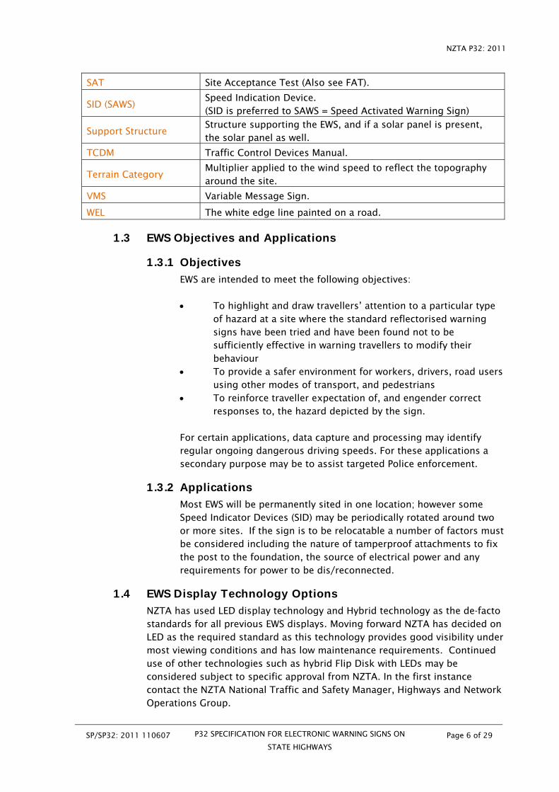
SAT Site Acceptance Test (Also see FAT).
SID (SAWS) Speed Indication Device. (SID is preferred to SAWS = Speed Activated Warning Sign)
Support Structure Structure supporting the EWS, and if a solar panel is present, the solar panel as well.
TCDM Traffic Control Devices Manual.
Terrain Category Multiplier applied to the wind speed to reflect the topography around the site.
VMS Variable Message Sign.
WEL The white edge line painted on a road.
1.3 EWS Objectives and Applications
1.3.1 Objectives
EWS are intended to meet the following objectives: To highlight and draw travellers’ attention to a particular type
of hazard at a site where the standard reflectorised warning signs have been tried and have been found not to be sufficiently effective in warning travellers to modify their behaviour
To provide a safer environment for workers, drivers, road users using other modes of transport, and pedestrians
To reinforce traveller expectation of, and engender correct responses to, the hazard depicted by the sign.
For certain applications, data capture and processing may identify regular ongoing dangerous driving speeds. For these applications a secondary purpose may be to assist targeted Police enforcement.
1.3.2 Applications
Most EWS will be permanently sited in one location; however some Speed Indicator Devices (SID) may be periodically rotated around two or more sites. If the sign is to be relocatable a number of factors must be considered including the nature of tamperproof attachments to fix the post to the foundation, the source of electrical power and any requirements for power to be dis/reconnected.
1.4 EWS Display Technology Options
NZTA has used LED display technology and Hybrid technology as the de-facto standards for all previous EWS displays. Moving forward NZTA has decided on LED as the required standard as this technology provides good visibility under most viewing conditions and has low maintenance requirements. Continued use of other technologies such as hybrid Flip Disk with LEDs may be considered subject to specific approval from NZTA. In the first instance contact the NZTA National Traffic and Safety Manager, Highways and Network Operations Group.
NZTA P32: 2011
SP/SP32: 2011 110607 P32 SPECIFICATION FOR ELECTRONIC WARNING SIGNS ON
STATE HIGHWAYS
Page 7 of 29
1.4.1 Light Emitting Diode and Hybrid
The dominant technologies in the market today are:
LED LED technology utilises a single or a cluster of solid-state diodes that form a single pixel. When electrical current is applied, the diode glows. The current to each pixel is turned on or off to form the characters of the displayed message. This is currently the default NZTA technology of choice.
Hybrid A typical hybrid EWS utilizes both flip disk and either fibre optic or LED technology. Each flip disk has a hole for light to pass through. The light is generated by a fibre optic bundle or LED pixel. When the pixel is activated the disk is flipped, allowing light to pass through the hole while displaying the reflective side of the disk to traffic. When the pixel is off its reflective surface is rotated, or flipped, blocking the light source.
2. Display Graphics, Messages, and Cabinet Attributes
2.1 Display Graphics and Messages
2.1.1 Introduction
All EWS must comply with current legislation including all symbols, appearance, wording, colours and operation.
NZTA P32: 2011
SP/SP32: 2011 110607 P32 SPECIFICATION FOR ELECTRONIC WARNING SIGNS ON
STATE HIGHWAYS
Page 8 of 29
Where a EWS is one of those shown below, the appearance of the display, and the choice of messages shall conform to the following, unless otherwise specified by NZTA. Any new signs must have their words/fonts/symbols/LED layouts approved by gazette notice or TCD Rule. The proportion of the symbol in relation to the rest of the sign, and its placement relative to any characters, shall closely match the respective illustrations provided in this section. The outline and appearance of the symbols shall match those in the Ministry of Transport Traffic Devices Control Specification, and the Land Transport Rule – Traffic Control Devices. The graphics, font layouts, and LED arrangements are shown as appropriate for 700 x 700, or 700 x 1000mm signs. If a larger sign is to be specified then a fresh layout of LEDs need to be designed, and agreement obtained for this design from the NZTA National Traffic and Safety Manager, Highways and Network Operations Group. Designers should reference: Traffic Note 57 “Active Warning Signs (not at schools) -
Guidelines” Relevant Traffic Notes Manual of Traffic Signs and Markings (MOTSAM) Traffic Control Devices Manual (TCDM).
2.1.2 Speed Indication Device
Character height of reflective display text: Min 150mm.
Character height of LED number: Min 200mm.
Colour of LED number: Yellow
NZTA P32: 2011
SP/SP32: 2011 110607 P32 SPECIFICATION FOR ELECTRONIC WARNING SIGNS ON
STATE HIGHWAYS
Page 9 of 29
Note: the Speed Indication Device will normally consist of a reflective sign mounted immediately above the electronic sign cabinet. In that case both components will make up the total display face and must conform to the regulatory requirements. Designers should reference Traffic Note 23 “Speed Indicator Devices”. The display controller shall incorporate an adjustable lower threshold which, when it is not exceeded, results in the sign remaining blanked. This threshold will typically be set 20 km/h below the posted speed limit. When the nominated lower threshold is exceeded the approaching vehicle’s speed shall be displayed as a figure in km/h. When the nominated upper threshold is exceeded the speed figure shall be replaced by the message “SLOW DOWN”. When the message “SLOW DOWN” is displayed, the words “SLOW” and “DOWN” shall alternate at one second intervals. The upper threshold will typically be set at either 5km/h or 10km/h above the posted speed limit. The upper threshold to switch from displaying the speed to displaying “SLOW DOWN” shall be adjustable in 5km/h steps between 50 – 90km/h.
NZTA P32: 2011
SP/SP32: 2011 110607 P32 SPECIFICATION FOR ELECTRONIC WARNING SIGNS ON
STATE HIGHWAYS
Page 10 of 29
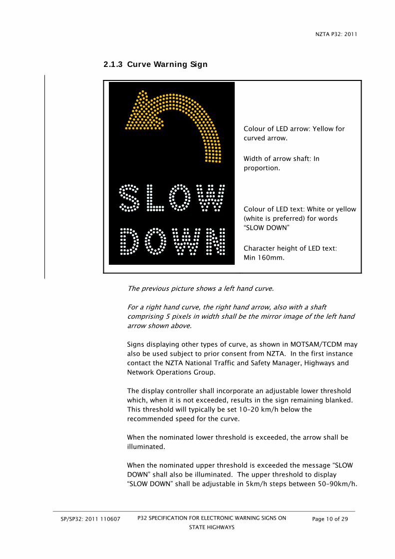
2.1.3 Curve Warning Sign
Colour of LED arrow: Yellow for curved arrow.
Width of arrow shaft: In proportion.
Colour of LED text: White or yellow (white is preferred) for words “SLOW DOWN”
Character height of LED text: Min 160mm.
The previous picture shows a left hand curve. For a right hand curve, the right hand arrow, also with a shaft comprising 5 pixels in width shall be the mirror image of the left hand arrow shown above. Signs displaying other types of curve, as shown in MOTSAM/TCDM may also be used subject to prior consent from NZTA. In the first instance contact the NZTA National Traffic and Safety Manager, Highways and Network Operations Group. The display controller shall incorporate an adjustable lower threshold which, when it is not exceeded, results in the sign remaining blanked. This threshold will typically be set 10–20 km/h below the recommended speed for the curve. When the nominated lower threshold is exceeded, the arrow shall be illuminated. When the nominated upper threshold is exceeded the message “SLOW DOWN” shall also be illuminated. The upper threshold to display “SLOW DOWN” shall be adjustable in 5km/h steps between 50–90km/h.
NZTA P32: 2011
SP/SP32: 2011 110607 P32 SPECIFICATION FOR ELECTRONIC WARNING SIGNS ON
STATE HIGHWAYS
Page 11 of 29
2.1.4 Cycle Warning Sign
Colour of LED lanterns & graphic: Yellow.
Lanterns: Four. One in each corner, as shown.
The display controller shall incorporate an adjustable function that when activated by a cyclist riding past a cyclist detection system (usually cycle induction loops), and/or an activation button pushed by the cyclist, will illuminate the display for an adjustable pre-set period. The length of the illumination period shall be adjustable up to 10 minutes, by intervals of not greater than five seconds. The length of illumination period selected at any given site will normally be decided by ride through. This sign can also be specified with the cycle facing left for use when that is the direction of risk, e.g. when the sign is installed on the right hand side of the road. In circumstances where a cyclist activating the sign cannot see if the display is on, consideration may be given to adding a yellow or amber “on” light to the rear of the sign.
NZTA P32: 2011
SP/SP32: 2011 110607 P32 SPECIFICATION FOR ELECTRONIC WARNING SIGNS ON
STATE HIGHWAYS
Page 12 of 29
2.1.5 Rural School Warning Sign
Colour of LED lanterns and graphic: Yellow.
Lanterns: Two. One in each of the top corners, as shown.
Character height of text: Min 160mm.
If a 1.5 or 2 times larger sign is used (e.g. on 100km/h highway), double pitch text shall be used.
Colour of text: White or yellow (white is preferred).
Designers should reference Traffic Note 56 “Active School Warning Signs - Guidelines”. The base unit activation controller shall: Be fully programmable with day/dates and on/off times to
illuminate the sign at set times during school days Allow planned school activities, holidays and daylight saving
time changes to be entered Activate the signs for an agreed length of time of between 20-
40 minutes, and then automatically turn the signs off Be fitted with a UPS and back up batteries capable of powering
the activation controller for at least 12 hours in a power outage Be lockable to prevent unauthorised access. Have a manual over-ride that will illuminate the sign for a
period of 20 minutes Be capable of easily generating an activity log of on-off times
and dates to provide evidence for speed enforcement prosecutions
The flashing lanterns shall be programmed to flash alternately when a vehicle approaches at a speed above the limit for the area during times that the sign is illuminated.
NZTA P32: 2011
SP/SP32: 2011 110607 P32 SPECIFICATION FOR ELECTRONIC WARNING SIGNS ON
STATE HIGHWAYS
Page 13 of 29
A 50mm diameter shrouded rear facing white “on” light must be mounted on the back of each sign to provide confirmation to staff outside the school that the sign is on. The shrouded indicator light shall be readily visible in bright sunlight from a distance of at least 300m.
2.1.6 40km/h Variable Speed Limits in School Zones
Colour of “40”: White or yellow (white is preferred). Character height of “40”: Min 200mm. Colour of roundel LEDs: Red. Roundel width: In proportion. Lantern Colour: Yellow Lanterns: Four. One in each corner, as shown.
Character height of reflective display text: Min 150mm.
Designers should reference Traffic Note 37 “40km/h Variable Speed Limits in School Zones”, and Traffic Note 56 “Active School Warning Signs – Guidelines”. The base unit activation controller shall: Be fully programmable with day/dates and on/off times to
illuminate the sign at set times during school days Allow planned school activities, holidays and daylight saving
time changes to be entered Activate the signs for an agreed length of time of between 20-
40 minutes, and then automatically turn the signs off Be fitted with a UPS and back up batteries capable of powering
the activation controller for at least 12 hours in a power outage Be lockable to prevent unauthorised access. Have a manual over-ride that will illuminate the sign for a
period of 20 minutes Be capable of easily generating an activity log of on-off times
and dates to provide evidence for speed enforcement prosecutions
NZTA P32: 2011
SP/SP32: 2011 110607 P32 SPECIFICATION FOR ELECTRONIC WARNING SIGNS ON
STATE HIGHWAYS
Page 14 of 29
When the sign is not operating, the underlying “40” on the speed limit sign must not be discernible to approaching motorists. The flashing lanterns shall be programmed to flash alternate pairs when the 40km/h speed limit is displayed. (See Section 2.1.11). A 50mm diameter shrouded rear facing white “on” light must be mounted on the back of each sign to provide confirmation to staff outside the school that the sign is on. The shrouded indicator light shall be readily visible in bright sunlight from a distance of at least 300m.
2.1.7 Slippery Surface Warning Sign
Colour of LED graphic: Yellow.
Colour of LED text: White or yellow for words “SLOW DOWN” (White is preferred).
Character height of text: min 160mm.
The display controller shall incorporate an adjustable lower threshold which, when it is not exceeded, results in the sign remaining blanked. This threshold will typically be set 10–20km/h below the posted speed limit. When the nominated lower threshold is exceeded, the graphic shall be illuminated. When the nominated upper threshold is exceeded the message “SLOW DOWN” shall also be illuminated. The upper threshold to display “SLOW DOWN” shall be adjustable in 5km/h steps between 50–90km/h.
2.1.8 Hidden Queue Warning Sign The “Hidden Queue” sign may be a changeable message sign (CMS), or a full VMS, as appropriate.
NZTA P32: 2011
SP/SP32: 2011 110607 P32 SPECIFICATION FOR ELECTRONIC WARNING SIGNS ON
STATE HIGHWAYS
Page 15 of 29
Designers should reference Traffic Note 57 “Active Warning Signs (Not at Schools) - Guidelines”. The display shall be triggered by an electrical signal from detector loops or other suitable detection devices installed in appropriate positions. The message is “HIDDEN QUEUE” The sign shall illuminate when the detection system detects a queue forming. The sign shall blank immediately when the queue dissipates.
2.1.9 Character Height
The Rule requires a minimum character height for reflectorised lettering of 150mm. The Rule for a LED display requires a minimum character height of 160mm. However for speed environments above 70km/h on high volume roads, consideration should be given to proportionally increasing the size of the sign by 25% and increasing the LED character height to at least 200mm to ensure approaching travellers have adequate reading time.
2.1.10 Font
The following shall apply to the display fonts and text layout:
Character spacing shall be equal to or greater than the width of down stroke (pitch), i.e. where a double pitch is used, the blank space between characters shall be equal to or greater than two pixels.
The variable display lettering shall utilise traffic fonts recognised by NZTA.
The static reflective sign lettering shall utilise Type E Modified font.
2.1.11 Symbols
Symbol layout shall match as closely as possible the symbol published in the MOTSAM / TCDM. The size of the symbol is to be maximised without distortion to fit a display area of 600mm x 480mm. The LEDs shall be set out in such a manner so that the symbol appears as a single block.
2.1.12 Border
All EWS shall have a black border with a minimum width of 50mm around the display.
NZTA P32: 2011
SP/SP32: 2011 110607 P32 SPECIFICATION FOR ELECTRONIC WARNING SIGNS ON
STATE HIGHWAYS
Page 16 of 29
2.1.13 Lanterns
Where lanterns are required:
They shall each be at least 44mm in diameter (and proportionally larger if the size of the sign is increased).
Each lantern shall consist of LEDs arranged in a circle with an infill pattern of LEDs, similar to that shown on the Cycle Warning Sign image in Section 2.
Lanterns must be of sufficient brightness to draw attention to, but not distract from, the sign or dazzle travellers.
If sun strike is likely to be an issue protective cowls should be installed.
When activated, the lanterns shall flash alternately at 1 Hertz. Where four lanterns are included, the lanterns shall flash top
together / bottom together / top together etc.
2.2 Electronic Display Attributes
2.2.1 Optical Performance
Except where explicitly defined by this manual the optical performance elements of the variable display shall be in accordance with the BS EN12966-1:2005. Display Flicker The image displayed on a message frame shall be such that it does not appear to flicker to the normal human eye. The image shall be such that a light pulse must be displayed in accordance with BS EN12966-1:2005 Section 7.7.
2.2.2 Viewing Angle
The LED elements for EWS shall have a minimum viewing angle of 20 degrees i.e. 10 degrees either side of the optical axis; and a maximum viewing angle of 30 degrees i.e. 15 degrees either side of the optical axis. All LEDS within any given EWS unit will have the same viewing angle. A pixel may consist of one LED. If a pixel is made up of two or more LED’s, the LED’s shall be grouped to form a symmetrical, circular shaped pixel in the display matrix. The luminous intensity of the pixel shall not decrease by more than 50% when viewed at the edge of the specified cone centred about the optical axis and perpendicular to the surface of the display. The luminance for different pixels shall not vary by more than ± 20% of the mean output of all the pixels. The display must comply with EN12966-1:2005 Section 7.5.
NZTA P32: 2011
SP/SP32: 2011 110607 P32 SPECIFICATION FOR ELECTRONIC WARNING SIGNS ON
STATE HIGHWAYS
Page 17 of 29
In case of doubt any testing shall be performed in accordance with EN12966-1:2005 Section 9.3.
2.2.3 LEDs
EWS vendors must supply evidence that LEDs supplied as part of any EWS sign meet the quality, life expectancy, candela ratings and batch requirements outlined in this document and any referenced external standard. Details of the current rating of the proposed LEDs to be used and what actual current they will be driven at to meet the candela requirements of NZTA for the EWS required, shall also be provided. LEDs shall all be sourced from the same batch / bin to mitigate minor variations in colour. No LED or group of LEDs shall be “overdriven” or supplied additional current such that the stated LED life expectancy is compromised, to achieve the candela ratings required under TR-2136 and/or EN 12966. (NZTA’s standard for EWS LED life expectancy is 150,000 hours). All soldering of LEDs required to form pixels will be of a type that meet viewing angle performance levels set out in this Specification. Pixels and or pixel mounting blocks shall be modular and easy to swap/replace without requiring any soldering or any other form of heat based bonding to other electrical components as part of the process.
2.2.4 Colours of LEDs
The LED pixels shall display a yellow colour, or white for certain applications, as listed and illustrated in Section 2.1. When the colour coordinates are measured, they shall be in accordance with EN12966-1 9.3.5. The chromaticity of the colours is defined in accordance with CIE 1931 standard colorimetric observer as referenced in CIE publications. The chromaticity limits for the x y positions shall be as shown in table 2 or table 3 in the EN12966-1. The display background shall be matt black.
2.2.5 Variable Display Intensity
The EWS shall incorporate a photo-sensor to adjust the intensity of the LED’s according to ambient light. The photo-sensor operation shall comply with EN12966-1:2005.
2.2.6 Variable Display Refresh
Complete blanking of one display and simultaneous generation of the next required display shall appear instantaneous. The time to display a fully populated message (i.e. all pixels active) generated at the EWS controller unit shall not exceed 0.5 second from a blank state.
NZTA P32: 2011
SP/SP32: 2011 110607 P32 SPECIFICATION FOR ELECTRONIC WARNING SIGNS ON
STATE HIGHWAYS
Page 18 of 29
When the vehicle speed is displayed, the refresh rate shall be set at a level that updates changes in speed at 800 milliseconds intervals unless otherwise agreed with NZTA.
2.3 Cabinet Attributes
2.3.1Cabinet Design
The structural design of the EWS cabinet, including the load on the sign face and mounting hardware, shall comply with the requirements of the NZTA Bridge Manual - SP/M/022. The cabinet must be sufficiently strong and rigid to support its own weight on the vertical support post in wind speeds up to 45m per second from any direction. The sign cabinet shall be constructed from sheet metal (aluminium or mild steel) treated as necessary to provide the required protection and mechanical strength for the application and environment. Materials used shall ensure deterioration due to atmospheric and/or local environmental conditions shall have no detrimental effect on the structural integrity or visual appearance (including colour fading or corrosion) of the finished cabinet for a period of not less than ten (10) years. Contact between untreated, dissimilar metals shall be avoided. The cabinet shall be designed such that any riveted side panels fit under a lip/edge/flashing to prevent exposure to water ingress. The cabinet shall be constructed to present a clean, neat appearance. The equipment located within the cabinet shall be protected from moisture, dust, dirt, and corrosion. The cabinet shall provide a minimum IP55 ingress protection as defined in AS 1939 -1990. As far as practicable the design shall ensure that no untreated/unfiltered external air is able to come into contact with any electronic equipment within the sign. The design shall ensure that the sign display and control elements are easily accessible and removable for maintenance purposes. Display elements shall be designed such that replacement requires only the loosening of accessible screw fixings or other suitable fastening arrangement and disconnection of power or control connections only. The cabinet interiors should be non-corrosive metal cage support frames to mount the display elements. The frame support shall be able to withstand and minimize vibration. All power supply cabling shall enter the sign housing through appropriately constructed, sealed and glanded entry holes.
NZTA P32: 2011
SP/SP32: 2011 110607 P32 SPECIFICATION FOR ELECTRONIC WARNING SIGNS ON
STATE HIGHWAYS
Page 19 of 29
The front of the cabinet shall include a UV stabilized, and UV filtering, polycarbonate front panel (not < 4mm) with anti-glare treatment incorporated, covering the LED display elements.
2.3.2 Cabinet Size
The regulatory minimum cabinet dimensions for the cycle warning sign are 700mm for both width and height, and for the other signs are 700mm wide and 1000mm high. The cabinet width or height (which includes the cabinet and any reflective sign immediately above and appearing continuous with the cabinet) may exceed this figure, and the cabinet may be square or rectangular in outline. Note the surface area of the cabinet, any solar panel, and the mounting height, all impact on the wind loading design of the support structure.
2.3.3 Cabinet Colour and Labels
The front of the cabinet shall be coloured matt black. Where the display includes a reflective sign (e.g. a SID may consist of a reflective “YOUR SPEED” sign above a LED display), the reflective sign must contain a black border, and should consist of a black lettering on a reflectorised white background. The back, top, bottom and sides of the cabinet shall be coloured aircraft grey to No 693 as referred to in BS381C or similar, to harmonise with the surroundings, and to minimise solar gain / overheating. The finish shall be semi-gloss to reduce the effects of specular glare. A label with an appropriate phone number shall be affixed to the back of the EWS so that the RCA can be contacted if the EWS malfunctions.
2.3.4 Display Controls and Accessibility
Any controls to adjust upper and lower thresholds, length of illumination time etc must have visible calibration, be positioned inside the cabinet, and be easily adjustable onsite.
2.3.5 Maintenance and Access
Cabinets shall have flush fitting lockable doors or access points. Unless specified otherwise all cabinets shall have an identical key, and the supplier shall provide at least 4 copies of the key. Doors may utilise pressure seals to ensure an air/watertight fit. Full access to the internal components for installation, testing and/or maintenance purposes, shall be easily accomplished both with the sign in place and disconnected from the structure.
NZTA P32: 2011
SP/SP32: 2011 110607 P32 SPECIFICATION FOR ELECTRONIC WARNING SIGNS ON
STATE HIGHWAYS
Page 20 of 29
2.3.6 Environmental Protection
Where the EWS are to be used in cold environments, the cabinet may require a heating system to prevent the accumulation of condensation. This may be achieved as a direct result of heat being generated from power supplies in the sign. A heating element (such as a heat strip or wire) may need to be installed around the front panel to prevent ice or frost accumulation on the sign face. Screened weep holes may be provided to allow the drainage of any water that may collect in the cabinet and a suitable moisture inhibitor may be used.
2.3.7 Maximum Weight
At certain locations the EWS will need to meet frangibility requirements. As some EWS must be relocatable, the maximum weight of the support post, display cabinet including batteries, static sign, and any solar panel must not exceed 80kg unless prior agreement has been obtained from NZTA. Note: For relocatable signs, no part on its own should weigh more than 25kg unless prior agreement has been obtained from NZTA. This is a safety requirement.
3. Display Activation
3.1 Radar
Where the EWS is radar activated, the radar shall meet the following requirements: The radar shall be activated by an approaching vehicle only, and not one travelling in the opposite direction. It shall have a normal operating range of approximately 200m. The radar unit shall be totally enclosed within the display cabinet, and be fixed to an easily aimed adjustable mounting e.g. a gimbal type. Once a vehicle enters the radar field, the radar must be consistently capable of registering the speed and sending a message to the display in <100 milliseconds. The radar shall be accurate to ± 2%
Technical specifications are to be provided by the supplier.
NZTA P32: 2011
SP/SP32: 2011 110607 P32 SPECIFICATION FOR ELECTRONIC WARNING SIGNS ON
STATE HIGHWAYS
Page 21 of 29
3.2 Induction Loop Where a Cyclist EWS is activated by an induction loop, the detection system shall meet the following requirements:
Through loop design and/or positioning on the roadway, the incidence
of ghost triggering from motor vehicles must be minimal to preserve the credibility of the sign’s message
Specialised induction loops capable of distinguishing between bicycles and motor vehicles should be considered at the design evaluation stage
The position of the cyclist loops shall be marked with a diamond pattern on the road way, and the background colour of the surface patch (where coloured) shall be green.
3.3 Wireless
Where a EWS is activated by wireless, the wireless unit should meet the following requirements:
Ideally there will be a direct line of sight from the antenna to the
receivers located on the signs Radio equipment shall operate in a band width approved by NZTA
National Office CIS Manager. For Rural School EWS the following requirements shall also be met: An antenna is to be placed on the outside of the school building and
connected to the control box The control box should be located at a secure place within the school
grounds (e.g. the Principal’s office) where only authorised personnel can have access to it.
4. Data Capture and Download, Remote Diagnostics
4.1 Data Capture and Download
For applications where NZTA requires the EWS to record and store data, the following data fields are required for each vehicle that is detected even when the display is not displaying a message: Date: Day, month, year Time: Hour, minute Speed: Maximum speed Where data is to be stored it shall be as a coma separated file (CSV). Unless otherwise agreed, the storage capacity in the display cabinet must allow the data from a minimum of 64,000 events to be stored. The oldest data shall be written over first.
NZTA P32: 2011
SP/SP32: 2011 110607 P32 SPECIFICATION FOR ELECTRONIC WARNING SIGNS ON
STATE HIGHWAYS
Page 22 of 29
Unless otherwise specified, each EWS must be capable of remotely downloading the data by one of the cellular networks specified by NZTA. NZTA National Office CIS Manager shall be consulted as to the modem specification. The EWS must also be capable of on-site downloading of data onto a laptop or storage device via a USB port located inside the display cabinet.
4.2 Remote Diagnostics
Where a cellular modem is fitted the EWS shall be capable of sending a text message to a nominated cell phone number when: 80% of the data storage capacity is reached Mains power is lost or battery charge level is low (whichever is
applicable)
5. Power Supply: Mains, Solar, Batteries
5.1 General
5.1.1 General Requirements
For all EWS powered from mains or street light circuits, the supply shall be single phase, 230v (± 5%), 15 ampere, 50 Hz AC unless otherwise specified. The voltage shall be stepped down to no more than 12 volts before the cable runs up the support structure. The adaptor will normally be located in a cabinet mounted on a plinth at ground level. If the power is supplied from a streetlight, it may be possible to accommodate the adaptor inside the base of the light mast. Any ground level cabinet must be positioned at least two meters horizontal distance from the EWS to reduce the opportunity for vandals to reach the EWS. The ground level cabinet shall be: Lockable Water tight Mounted on a concrete plinth Include the necessary conduits to the EWS
All electrical work shall comply with the requirements of the New Zealand Electricity Regulations and AS/NZS 3000: Wiring Rules.
5.1.2 Electrical Surge Protection
All display equipment shall be internally protected against damage resulting from:
Lightning strikes near the EWS site Electrical transients on power cabling
NZTA P32: 2011
SP/SP32: 2011 110607 P32 SPECIFICATION FOR ELECTRONIC WARNING SIGNS ON
The EWS shall incorporate a resetting circuit breaker to automatically reset after a power surge.
5.2 Mains Power
5.2.1 Network Connection and Supplier Agreement
When final site selection has been decided, a power contractor is tasked with arranging power supply to the sites. Initiating this work at the earliest possible stage avoids potential delays to the project. The party arranging power is to:
Complete application for the supply of electricity/network
connection and submit to the chosen retailer (or delegate to the installation contractor). Include details of existing connections and account details as appropriate so that accounts are addressed correctly.
Provide details of the estimated load for the sign so that the
electricity usage is calculated correctly for the monthly invoicing.
The electricity retailer should then authorise/instruct the
network company to establish an ICP number. Once the installation has been inspected a revenue meter will be installed by the electricity retailer (or their agent) and the connection certified for livening.
Confirm the retailer’s requirements for metering. Given the low
power usage, NZTA preference is for an annual meter reading.
The cabling contractor shall be instructed to leave five meters of cable lightly buried in the ground at the pegged position, unless the ground level plinth and conduits are already installed, in which case two meters of cable lightly buried beside the pad under the conduit opening will suffice. This should provide sufficient length of cable to reach the adapter mounted in the ground level cabinet. Note that consent from NZTA is required before cabling installation is undertaken in the road reserve.
NZTA P32: 2011
SP/SP32: 2011 110607 P32 SPECIFICATION FOR ELECTRONIC WARNING SIGNS ON
STATE HIGHWAYS
Page 24 of 29
5.3 Solar Panels
Where a solar panel is fitted to a EWS it shall meet the following requirements: Exposure to one sunny day should be sufficient to recharge the batteries for a further 72 hours of operation. The solar panel shall prevent birds from perching on the panel. This may be achieved either through having an edge that offers no foot holds, or through fitting an effective anti-perching device to the uppermost edge. The fixings that secure the panel to the post shall be sufficiently tamper proof to present a high degree of resistance to unauthorised removal. The underside of the panel shall be adequately packed and supported. The requirement to choose a site that will not be unduly affected by shading from trees, or the nearby topography should have been covered during the site selection process. See the Notes section 3.1.2 Clear Sight Distance. The solar panels shall be tilted at a 35 degree angle. Solar panels shall be orientated to face directly north.
Technical specifications are to be provided by the supplier.
5.4 Battery Requirements
Unless specified, storage batteries are not required for EWS powered from a 24/7 mains supply. They are however required for EWS that are powered by discontinuous streetlight circuits, and from solar panels. Batteries for EWS powered from solar panels must have sufficient capacity to operate the EWS for 72 hours without recharging. Exposure to one sunny day should be sufficient to recharge the batteries for a further 72 hours of operation. Where batteries are used and a cellular modem is fitted, the EWS shall be capable of sending a text message to a nominated cell phone number when battery charge levels are low. Technical specifications are to be provided by the supplier.
6. Support Structure and Foundation Design Requirements
6.1 Standard Support Structure and Foundations
Standard solutions are based on the 2008 Road Safety Manufacturers’ Association (RSMA) standard for small signs as a means of compliance document for NZ Transport Agency’s Performance Based Specification for Traffic Signs (NZTA P24) to meet the wind speed requirements of AS/NZS 1170:2002.
NZTA P32: 2011
SP/SP32: 2011 110607 P32 SPECIFICATION FOR ELECTRONIC WARNING SIGNS ON
STATE HIGHWAYS
Page 25 of 29
The preference is for a frangible aluminium post without a slipbase. The maximum diameter aluminium post currently available that does not require a slipbase is a single, fluted, 114mm outer diameter aluminium post, of 4.7mm wall thickness, manufactured in Grade 6261-T5 (255MPa yield strength). The post shall have a powder coated finish and be coloured white. If the surface area of the sign and any solar panel is too great for a 114mm diameter post then a larger post with a slipbase may be considered. If the sign is protected by a guard rail, or is in a speed environment less than 70 km/h, the requirements for frangibility may not be necessary but should be considered as appropriate. To ensure reasonable visibility and to suppress vandalism, the bottom of the display cabinet shall be mounted 3m above ground level unless otherwise agreed with NZTA in which case every effort should be made to achieve a mounting height of at least 2.75m. If a solar panel is fitted it must be secured in a manner that will effectively suppress the opportunity for theft. The post shall be designed to support the display cabinet, static sign, and solar panel in regional wind speeds up to 45m per second from any direction. The standard design is based on a rural terrain situation (Category 2) with a maximum ground slope of 1 in 5. The fluted post shall be inserted into a foundation socket designed in such a manner as to prevent rotation caused by wind or deliberate vandalism. The post must be secured to the socket with a tamper resistant fixing, and be removable. All cabling up or down the post must be run internally. Non-standard designs may be approved through NZTA National Office subject to them meeting the P24 Specification.
6.2 Foundation Requirements
The Contractor is to be familiar with the assumed foundation soil properties as detailed in the RSMA standard for small signs. The standard foundation is a 400mm diameter concrete footing (concrete compressive strength of 17.5MPa) with a minimum post embedment of 1.5m. If the foundation soil properties encountered during construction differ from those assumed in design, the Contractor is to immediately cease work at the site and bring this to the attention of the NZTA representative, who will assess the unforeseen conditions and advise how construction is to proceed. The standard solution foundation soil is based on Appendix C and Table C1 of the RSMA standard and must fulfil the following requirements:
NZTA P32: 2011
SP/SP32: 2011 110607 P32 SPECIFICATION FOR ELECTRONIC WARNING SIGNS ON
STATE HIGHWAYS
Page 26 of 29
Ground water table is below the proposed foundation depth (unless
specifically allowed) Topsoil, very soft or very loose surface sediments shall not be included
in the embedment depth given above. In no case should this be greater than a depth of 200mm
No peat is present.
6.3 Applicable Design Standards
Standard solution design is based on the 2008 Road Safety Manufacturers’ Association (RSMA) standard for small signs as a means of compliance document for NZ Transport Agency’s Performance Based Specification for Traffic Signs (NZTA P24) to meet the wind speed requirements of AS/NZS 1170:2002. Specific design of EWS support structures if required to be carried out, shall be in accordance with the following standards: AS/NZS 1170: Structural design actions AS/NZS 1664: Aluminium structures AS/NZS 1866: Aluminium and aluminium alloys – Extruded rod, bar, solid and
hollow shapes AS/NZS 4506: Metal finishing – Thermoset powder coatings AS/NZS 4671: Steel reinforcing materials NZS 3104: Specification for Concrete Production NZS 3124: Specification for concrete construction for minor works
7. Security Options
7.1 Design Options
EWS, and in particular some of the components such as batteries and solar panels, are attractive targets for theft. Many of the signs will also be subject to acts of vandalism that may include graffiti, and objects hurled from moving vehicles. As covered elsewhere in this Specification, the bottom of the EWS should be 3m above ground level to suppress vandalism, and the LED displays protected from thrown objects by a sheet of polycarbonate. Other options to enhance security include: A steel rather than aluminium pole. This may require a frangible base,
or location behind an approved guard rail. Where the sign is within cell phone coverage, installing a device that
will send a text message when the door is opened (switch or light sensor), the sign is tilted (level sensor), or when the power is interrupted (in which case a battery is required).
NZTA P32: 2011
SP/SP32: 2011 110607 P32 SPECIFICATION FOR ELECTRONIC WARNING SIGNS ON
STATE HIGHWAYS
Page 27 of 29
Embedding a GPS tracking device in the sign.
8. Testing and Commissioning of EWS
8.1 Factory Acceptance Testing (FAT)
Prior to internal system testing of the EWS, the Contractor shall provide the Engineer with copies of the FAT testing programmes to be carried out for all EWS components. The Contractor shall undertake witnessed FAT as required by the Engineer, on the EWS following completion and prior to installation. The FAT may include, but is not limited to: Optical testing. This may be based on the supplier providing a copy of
the test results for identical equipment from an independent accredited testing organisation.
Display of any messages in all formats Environmental protection systems
In all cases, the Contractor shall provide full details of testing and acceptance criteria for the above FAT for the Engineers approval prior to site installation.
8.2 Site Acceptance Testing (SAT)
The Contractor shall undertake SAT on the EWS as required by the Engineer. This SAT may include, but is not limited to: Any repeat FAT testing as deemed appropriate Testing of the power supply Testing the radar alignment and performance Testing the display performance Testing of the communications link(s) In all cases, the Contractor shall provide full details of testing and acceptance criteria for the above SAT for the Engineers approval prior to commissioning.
8.3 Commissioning
Following successful completion of all above FAT and/or SAT, including any modifications and repeat testing the EWS shall be deemed to be commissioned.
8.4 Traffic Management
Temporary Traffic Management (TTM) for all site activities shall conform to the NZTA Code of Practice for Temporary Traffic Management (COPTTM).
NZTA P32: 2011
SP/SP32: 2011 110607 P32 SPECIFICATION FOR ELECTRONIC WARNING SIGNS ON
STATE HIGHWAYS
Page 28 of 29
9. Warranties and Maintenance Period
9.1 Standard Warranty
Different suppliers have offered widely varying warranty conditions. It is important for the supplier to provide an appropriate warranty that does not leave a disproportionate amount of risk resting with NZTA. As a minimum the warranty conditions must ensure that in the event of failure due to faulty parts or workmanship in the first 12 months, the EWS will be repaired and reinstated at no cost to NZTA. It is recommended the following attributes are included: 12 month on-site warranty All significant faults (sign unable to display recognisable message), to
be addressed within three working days of supplier being notified for school signs, and five working days for all other signs.
9.2 Maintenance Period
The supply contract must include a requirement for the supplier to maintain the EWS for a period of at least one year following post-commissioning acceptance by NZTA.
10. Post Commissioning Documentation and Spare Parts
10.1 As Built Drawings
As built drawings shall be supplied by sign vendors and contractors and will include:
Support structures (if non-standard) Cabinet drawings Power supply arrangements
10.2 Operating Servicing and Maintenance Manuals
The Contractor shall supply an Operating Servicing and Maintenance Manual for all equipment supplied. This shall be carefully laid out with detailed operating procedures for the equipment and systems, including all software supplied. It shall be written in a format that is easily understood by the intended EWS operators. The manual shall document in detail the maintenance and service aspects of the equipment on an item-by-item basis. This shall include: List of Equipment including Part Numbers and availability; Routine Service/Maintenance Procedures; Troubleshooting Guide; Details of fault diagnostic features from the control centre;
NZTA P32: 2011
SP/SP32: 2011 110607 P32 SPECIFICATION FOR ELECTRONIC WARNING SIGNS ON
STATE HIGHWAYS
Page 29 of 29
Other fault diagnostic procedures to be followed; Testing Procedures; Circuit Diagrams.
10.3 Spare Parts
The contract specification for the procurement of the EWS shall ensure the EWS supplier provides appropriate maintenance services including, but not limited to, addressing:
Trained personnel Any agreements with third parties to provide services in remote
locations Equipment, tools and back up facilities Response times and clearance times, for urgent and non-urgent faults Routine preventative maintenance programme Reporting requirements for reactive and preventative maintenance Spare parts inventory.