60
1 P43DE3 User Manual Version 1.0 Published July 2009 Copyright©2009 ASRock INC. All rights reserved.

11111
P43DE3
User Manual
Version 1.0Published July 2009
Copyright©2009 ASRock INC. All rights reserved.
22222
Copyright Notice:Copyright Notice:Copyright Notice:Copyright Notice:Copyright Notice:No part of this manual may be reproduced, transcribed, transmitted, or translated inany language, in any form or by any means, except duplication of documentation bythe purchaser for backup purpose, without written consent of ASRock Inc.Products and corporate names appearing in this manual may or may not be regis-tered trademarks or copyrights of their respective companies, and are used only foridentification or explanation and to the owners’ benefit, without intent to infringe.
Disclaimer:Disclaimer:Disclaimer:Disclaimer:Disclaimer:Specifications and information contained in this manual are furnished for informa-tional use only and subject to change without notice, and should not be constructedas a commitment by ASRock. ASRock assumes no responsibility for any errors oromissions that may appear in this manual.With respect to the contents of this manual, ASRock does not provide warranty ofany kind, either expressed or implied, including but not limited to the implied warran-ties or conditions of merchantability or fitness for a particular purpose.In no event shall ASRock, its directors, officers, employees, or agents be liable forany indirect, special, incidental, or consequential damages (including damages forloss of profits, loss of business, loss of data, interruption of business and the like),even if ASRock has been advised of the possibility of such damages arising from anydefect or error in the manual or product.
This device complies with Part 15 of the FCC Rules. Operation is subject to thefollowing two conditions:(1) this device may not cause harmful interference, and(2) this device must accept any interference received, including interference that
may cause undesired operation.
CALIFORNIA, USA ONLYThe Lithium battery adopted on this motherboard contains Perchlorate, a toxicsubstance controlled in Perchlorate Best Management Practices (BMP) regulationspassed by the California Legislature. When you discard the Lithium battery inCalifornia, USA, please follow the related regulations in advance.“Perchlorate Material-special handling may apply, seewww.dtsc.ca.gov/hazardouswaste/perchlorate”
ASRock Website: http://www.asrock.com
33333
ContentsContentsContentsContentsContents1 Introduction1 Introduction1 Introduction1 Introduction1 Introduction ............................................................................................................................................................................................................................................................... 5 5 5 5 5
1.1 Package Contents .......................................................... 51.2 Specifications ................................................................. 61.3 Motherboard Layout ........................................................ 101.4 I/O Panel ......................................................................... 11
2 Installation2 Installation2 Installation2 Installation2 Installation ......................................................................................................................................................................................................................................................................... 13 13 13 13 132.1 Screw Holes ................................................................... 132.2 Pre-installation Precautions ............................................ 132.3 CPU Installation .............................................................. 142.4 Installation of Heatsink and CPU fan ............................... 162.5 Installation of Memory Modules (DIMM) ......................... 172.6 Expansion Slots (PCI and PCI Express Slots) ..................... 182.7 Jumpers Setup .............................................................. 192.8 Onboard Headers and Connectors .................................. 212.9 HDMI_SPDIF Header Connection Guide ......................... 262.10 SATAII Hard Disk Setup Guide ....................................... 272.11 Serial ATA (SATA) / Serial ATAII (SATAII) Hard Disks Installation ...................................................................... 282.12 Hot Plug Function for SATA / SATAII HDDs .................. 282.13 SATA / SATAII HDD Hot Plug Feature and Operation Guide .............................................................................. 292.14 Driver Installation Guide ................................................. 312.15 Installing Windows® 2000 / XP / XP 64-bit / VistaTM / VistaTM 64-bit Without RAID Functions ........................... 31
2.15.1 Installing Windows® 2000 / XP / XP 64-bit Without RAID Functions ................................................... 312.15.2 Installing Windows® VistaTM / VistaTM 64-bit Without RAID Functions ................................................... 32
2.16 Untied Overclocking Technology ................................... 33
3 BIOS S3 BIOS S3 BIOS S3 BIOS S3 BIOS SETUP UTILITYETUP UTILITYETUP UTILITYETUP UTILITYETUP UTILITY ....................................................................................................................................................................................................................... 34 34 34 34 343.1 Introduction .................................................................... 34
3.1.1 BIOS Menu Bar .................................................... 343.1.2 Navigation Keys ................................................... 35
3.2 Main Screen ................................................................... 353.3 OC Tweaker Screen ...................................................... 363.4 Advanced Screen ......................................................... 46
3.4.1 CPU Configuration ................................................ 473.4.2 Chipset Configuration ........................................... 49

44444
3.4.3 ACPI Configuration ............................................... 503.4.4 Storage Configuration ......................................... 513.4.5 PCIPnP Configuration ........................................... 533.4.6 Floppy Configuration ........................................... 543.4.7 Super IO Configuration ........................................ 543.4.8 USB Configuration ............................................... 55
3.5 Hardware Health Event Monitoring Screen .................. 563.6 Boot Screen................................................................... 57
3.6.1 Boot Settings Configuration .................................. 573.7 Security Screen ............................................................ 583.8 Exit Screen .................................................................... 59
4 Software Support4 Software Support4 Software Support4 Software Support4 Software Support ....................................................................................................................................................................................................................... 60 60 60 60 604.1 Install Operating System ............................................... 604.2 Support CD Information ................................................. 60
4.2.1 Running Support CD ............................................ 604.2.2 Drivers Menu ........................................................ 604.2.3 Utilities Menu ........................................................ 604.2.4 Contact Information .............................................. 60

55555
Chapter 1: IntroductionChapter 1: IntroductionChapter 1: IntroductionChapter 1: IntroductionChapter 1: IntroductionThank you for purchasing ASRock P43DE3 motherboard, a reliable motherboardproduced under ASRock’s consistently stringent quality control. It delivers excellentperformance with robust design conforming to ASRock’s commitment to quality andendurance.In this manual, chapter 1 and 2 contain introduction of the motherboard and step-by-stepguide to the hardware installation. Chapter 3 and 4 contain the configuration guide toBIOS setup and information of the Support CD.
Because the motherboard specifications and the BIOS software mightbe updated, the content of this manual will be subject to change withoutnotice. In case any modifications of this manual occur, the updatedversion will be available on ASRock website without further notice. Youmay find the latest VGA cards and CPU support lists on ASRock websiteas well. ASRock website http://www.asrock.comIf you require technical support related to this motherboard, please visitour website for specific information about the model you are using.www.asrock.com/support/index.asp
1.1 P1.1 P1.1 P1.1 P1.1 Packackackackackage Contentsage Contentsage Contentsage Contentsage ContentsASRock P43DE3 Motherboard
(ATX Form Factor: 12.0-in x 8.0-in, 30.5 cm x 20.3 cm)ASRock P43DE3 Quick Installation GuideASRock P43DE3 Support CDOne 80-conductor Ultra ATA 66/100/133 IDE Ribbon CableTwo Serial ATA (SATA) Data Cables (Optional)One I/O Panel Shield

66666
1 .21 .21 .21 .21 .2 SpecificationsSpecificationsSpecificationsSpecificationsSpecifications
Platform - ATX Form Factor: 12.0-in x 8.0-in, 30.5 cm x 20.3 cm CPU - LGA 775 for Intel® CoreTM 2 Extreme / CoreTM 2 Quad / CoreTM
2 Duo / Pentium® Dual Core / Celeron® Dual Core / Celeron®, supporting Penryn Quad Core Yorkfield and Dual Core Wolfdale processors- Compatible with all FSB1600/1333/1066/800MHz CPUs (see CAUTION 1)- Supports Hyper-Threading Technology (see CAUTION 2)- Supports Untied Overclocking Technology (see CAUTION 3)- Supports EM64T CPU
Chipset - Northbridge: Intel® P43- Southbridge: Intel® ICH10
Memory - Dual Channel DDR3 Memory Technology (see CAUTION 4)- 4 x DDR3 DIMM slots- Support DDR3 1600/1333/1066/800 non-ECC, un-buffered memory (see CAUTION 5)- Max. capacity of system memory: 16GB (see CAUTION 6)- Supports Intel® Extreme Memory Profile (XMP)
Expansion Slot - 1 x PCI Express 2.0 x16 slot (blue @ x16 mode)- 3 x PCI Express x1 slots- 2 x PCI slots
Audio - 7.1 CH Windows® VistaTM Premium Level HD Audio (VIA® VT1708S Audio Codec)
LAN - PCIE x1 Gigabit LAN 10/100/1000 Mb/s- Realtek RTL8111DL- Supports Wake-On-LAN
Rear Panel I/O I/O Panel- 1 x PS/2 Mouse Port- 1 x PS/2 Keyboard Port- 1 x Coaxial SPDIF Out Port- 1 x Optical SPDIF Out Port- 6 x Ready-to-Use USB 2.0 Ports- 1 x RJ-45 LAN Port with LED (ACT/LINK LED and SPEED LED)- HD Audio Jack: Side Speaker/Rear Speaker/Central/Bass/ Line in/Front Speaker/Microphone (see CAUTION 7)
Connector - 6 x SATAII 3.0Gb/s connectors, support NCQ, AHCI and “Hot Plug” functions (see CAUTION 8)- 1 x ATA133 IDE connector (supports 2 x IDE devices)- 1 x Floppy connector

77777
- 1 x IR header- 1 x COM port header- 1 x HDMI_SPDIF header- 1 x TPM header- CPU/Chassis/Power FAN connector- 24 pin ATX power connector- 8 pin 12V power connector- CD in header- Front panel audio connector- 3 x USB 2.0 headers (support 6 USB 2.0 ports) (see CAUTION 9)
BIOS Feature - 8Mb AMI BIOS- AMI Legal BIOS- Supports “Plug and Play”- ACPI 1.1 Compliance Wake Up Events- Supports jumperfree- SMBIOS 2.3.1 Support- CPU, DRAM, GTL REF, NB, NB GTL REF, SB Core, SB 1.1V, VTT, PLL Voltage Multi-adjustment- Supports I. O. T. (Intelligent Overclocking Technology)- Supports Smart BIOS
Support CD - Drivers, Utilities, AntiVirus Software (Trial Version) Unique Feature - ASRock OC Tuner (see CAUTION 10)
- Intelligent Energy Saver (see CAUTION 11)- Instant Boot- ASRock Instant Flash (see CAUTION 12)- Hybrid Booster:
- CPU Frequency Stepless Control (see CAUTION 13)- ASRock U-COP (see CAUTION 14)- Boot Failure Guard (B.F.G.)
Hardware - CPU Temperature Sensing Monitor - Chassis Temperature Sensing
- CPU/Chassis/Power Fan Tachometer- CPU Quiet Fan- Voltage Monitoring: +12V, +5V, +3.3V, CPU Vcore
OS - Microsoft® Windows® 2000 / XP / XP 64-bit / VistaTM / VistaTM 64-bit / Win7 compliant (see CAUTION 15)
Certifications - FCC, CE, WHQL- EuP Ready (EuP ready power supply is required) (see CAUTION 16)
* For detailed product information, please visit our website: http://www.asrock.com
88888
CAUTION!1. FSB1600-CPU will operate in overclocking mode.2. About the setting of “Hyper Threading Technology”, please check page 47.3. This motherboard supports Untied Overclocking Technology. Please read
“Untied Overclocking Technology” on page 33 for details.4. This motherboard supports Dual Channel Memory Technology. Before you
implement Dual Channel Memory Technology, make sure to read theinstallation guide of memory modules on page 17 for proper installation.
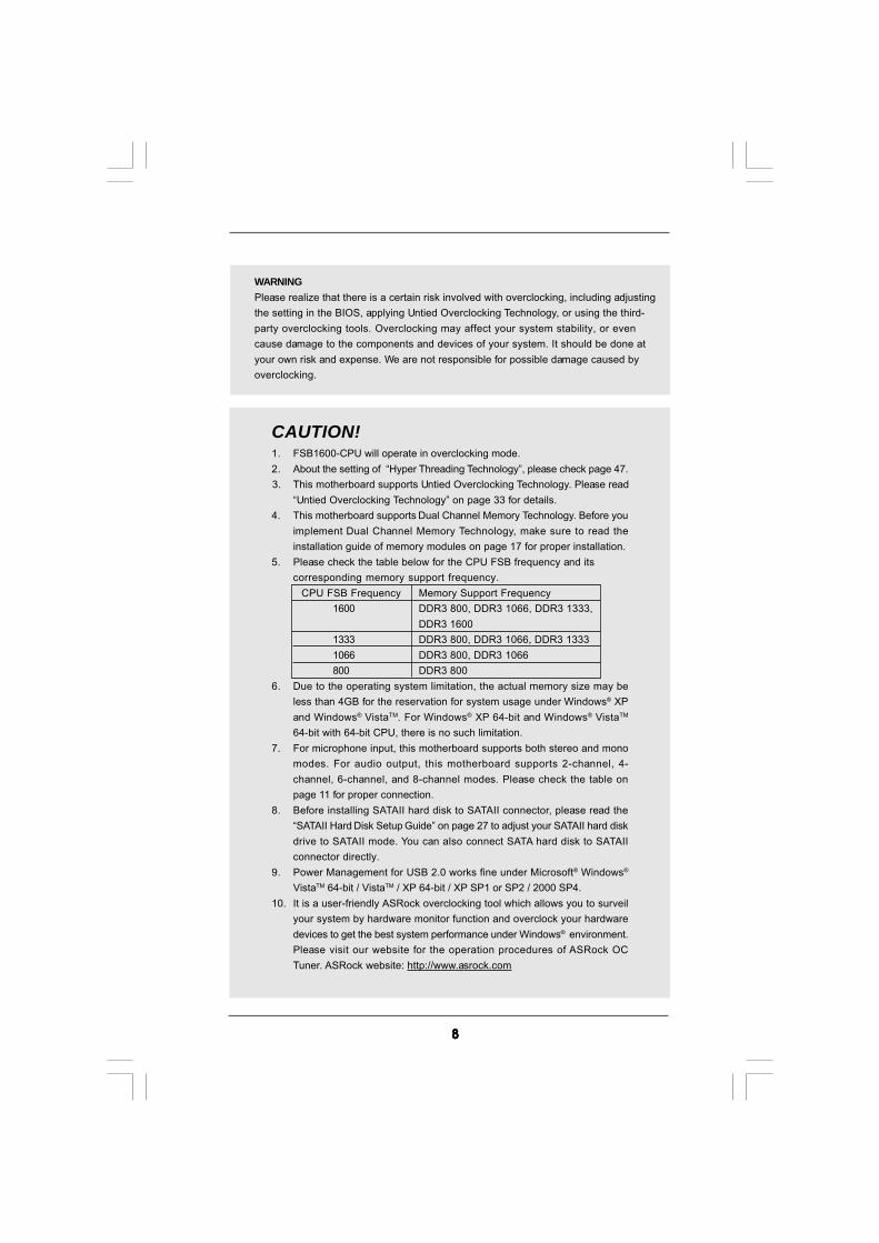
5. Please check the table below for the CPU FSB frequency and itscorresponding memory support frequency.
CPU FSB Frequency Memory Support Frequency1600 DDR3 800, DDR3 1066, DDR3 1333,
DDR3 16001333 DDR3 800, DDR3 1066, DDR3 13331066 DDR3 800, DDR3 1066800 DDR3 800
6. Due to the operating system limitation, the actual memory size may beless than 4GB for the reservation for system usage under Windows® XPand Windows® VistaTM. For Windows® XP 64-bit and Windows® VistaTM
64-bit with 64-bit CPU, there is no such limitation.7. For microphone input, this motherboard supports both stereo and mono
modes. For audio output, this motherboard supports 2-channel, 4-channel, 6-channel, and 8-channel modes. Please check the table onpage 11 for proper connection.
8. Before installing SATAII hard disk to SATAII connector, please read the“SATAII Hard Disk Setup Guide” on page 27 to adjust your SATAII hard diskdrive to SATAII mode. You can also connect SATA hard disk to SATAIIconnector directly.
9. Power Management for USB 2.0 works fine under Microsoft® Windows®
VistaTM 64-bit / VistaTM / XP 64-bit / XP SP1 or SP2 / 2000 SP4.10. It is a user-friendly ASRock overclocking tool which allows you to surveil
your system by hardware monitor function and overclock your hardwaredevices to get the best system performance under Windows® environment.Please visit our website for the operation procedures of ASRock OCTuner. ASRock website: http://www.asrock.com
WARNINGPlease realize that there is a certain risk involved with overclocking, including adjustingthe setting in the BIOS, applying Untied Overclocking Technology, or using the third-party overclocking tools. Overclocking may affect your system stability, or evencause damage to the components and devices of your system. It should be done atyour own risk and expense. We are not responsible for possible damage caused byoverclocking.
99999
11. Featuring an advanced proprietary hardware and software design,Intelligent Energy Saver is a revolutionary technology that deliversunparalleled power savings. In other words, it is able to provide excep-tional power saving and improve power efficiency without sacrificingcomputing performance. Please visit our website for the operation pro-cedures of Intelligent Energy Saver.ASRock website: http://www.asrock.com
12. ASRock Instant Flash is a BIOS flash utility embedded in Flash ROM.This convenient BIOS update tool allows you to update system BIOSwithout entering operating systems first like MS-DOS or Windows®. Withthis utility, you can press <F6> key during the POST or press <F2> key toBIOS setup menu to access ASRock Instant Flash. Just launch this tooland save the new BIOS file to your USB flash drive, floppy disk or harddrive, then you can update your BIOS only in a few clicks without prepar-ing an additional floppy diskette or other complicated flash utility. Pleasebe noted that the USB flash drive or hard drive must use FAT32/16/12 filesystem.
13. Although this motherboard offers stepless control, it is not recommendedto perform over-clocking. Frequencies other than the recommended CPUbus frequencies may cause the instability of the system or damage theCPU.
14. While CPU overheat is detected, the system will automatically shutdown.Before you resume the system, please check if the CPU fan on themotherboard functions properly and unplug the power cord, then plug itback again. To improve heat dissipation, remember to spray thermalgrease between the CPU and the heatsink when you install the PCsystem.
15. AHCI function is not supported under Windows® 2000 OS. It isrecommended to use IDE mode under Windows® 2000. Please refer topage 51 for detailed setup.
16. EuP, stands for Energy Using Product, was a provision regulated byEuropean Union to define the power consumption for the completed system.According to EuP, the total AC power of the completed system shall beunder 1.00W in off mode condition. To meet EuP standard, an EuP readymotherboard and an EuP ready power supply are required. According toIntel’s suggestion, the EuP ready power supply must meet the standard of5v standby power efficiency is higher than 50% under 100 mA currentconsumption. For EuP ready power supply selection, we recommend youchecking with the power supply manufacturer for more details.

1 01 01 01 01 0
1.3 Motherboard Layout1.3 Motherboard Layout1.3 Motherboard Layout1.3 Motherboard Layout1.3 Motherboard Layout
1 PS2_USB_PWR1 Jumper 20 USB 2.0 Header (USB8_9, Blue)2 ATX 12V Connector (ATX12V1) 21 USB 2.0 Header (USB10_11, Blue)3 CPU Fan Connector (CPU_FAN1) 22 System Panel Header (PANEL1, Orange)4 775-Pin CPU Socket 23 Chassis Speaker Header5 2 x 240-pin DDR3 DIMM Slots (SPEAKER 1, Purple)
(Dual Channel: DDR3_A1, DDR3_B1; Blue) 24 TPM Header (TPM1)6 2 x 240-pin DDR3 DIMM Slots 25 COM Port Header (COM1)
(Dual Channel: DDR3_A2, DDR3_B2; White) 26 Floppy Connector (FLOPPY1)7 ATX Power Connector (ATXPWR1) 27 HDMI_SPDIF Header8 Chassis Fan Connector (CHA_FAN1) (HDMI_SPDIF1, Yellow)9 IDE1 Connector (IDE1, Blue) 28 Infrared Module Header (IR1)10 Clear CMOS Jumper (CLRCMOS1) 29 PCI Slots (PCI1 - 2)11 SPI BIOS Chip 30 PCI Express x1 Slot (PCIE4)12 South Bridge Controller 31 PCI Express 2.0 x16 Slot (PCIE3, Blue)13 Primary SATAII Connector (SATAII_1 (Port 0), Red) 32 Front Panel Audio Header14 Secondary SATAII Connector (SATAII_2 (Port 1), Red) (HD_AUDIO1, Lime)15 Third SATAII Connector (SATAII_3 (Port 2), Red) ) 33 PCI Express x1 Slot (PCIE2)16 Fourth SATAII Connector (SATAII_4 (Port 3), Red) 34 PCI Express x1 Slot (PCIE1)17 Sixth SATAII Connector (SATAII_6 (Port 5), Red) 35 Internal Audio Connector: CD1 (Black)18 Fifth SATAII Connector (SATAII_5 (Port 4), Red) 36 Power Fan Connector (PWR_FAN1)19 USB 2.0 Header (USB6_7, Blue) 37 North Bridge Controller
IntelP43
Chipset
IntelICH10
AT
XP
WR
1
CD1
ATX12V11
PS2_USB_PWR1
SuperI/O
8MbBIOS
AUDIOCODEC
CPU_FAN1
CMOSBattery
IDE1
CLRCMOS1
1
CHA_FAN1
FLOPPY1
1
HD_AUDIO1
HDLED RESET
PLED PWRBTN
SPEAKER1
1
PANEL1
1
30
.5c
m(1
2.0
in)
20.3cm (8.0 in)
1 2 3 4 5 6
7
8
9
10
11
12
13
14
15
2324 22
16
171819202526
27
2829
30
DD
R3
_A
1(6
4b
it,2
40
-pin
mo
du
le)
DD
R3
_A
2(6
4b
it,2
40
-pin
mo
du
le)
1
HDMI_SPDIF1
IR1
1
To
p:
SID
ES
PK
Ce
nte
r:R
EA
RS
PK
Bo
ttom
:C
TR
BA
SS
To
p:
LIN
EIN
Ce
nte
r:F
RO
NT
Bo
ttom
:M
ICIN
PCI1
PCI2
PS
2
Mo
us
e
PS
2K
eyboard
USB 2.0T: USB4B: USB5
Top:RJ-45
33
34
35
PCI Express 2.0
Co
axialS
PD
IFO
ptical
SP
DIF
USB 2.0T: USB0B: USB1
COM1
1
LANPHY
USB6_7
11
DD
R3
_B
1(6
4b
it,2
40
-pin
mo
du
le)
DD
R3
_B
2(6
4b
it,2
40
-pin
mo
du
le)
SA
TA
II_
5(P
ort
4)
PCIE1
RoHS
FS
B1
60
0
USB 2.0T: USB2B: USB3
32
31
P4
3D
E3
DD
R3
1600
Du
alC
han
nel
21
PCIE2
PCIE4
PCIE3
TPM1
11
USB8_9
11
USB10_11
11
SA
TA
II_
3(P
ort
2)
SA
TA
II_
1(P
ort
0)
SA
TA
II_
6(P
ort
5)
SA
TA
II_
4(P
ort
3)
SA
TA
II_
2(P
ort
1)
PWR_FAN1
EuP Ready
36
37

1 11 11 11 11 1
1 .41 .41 .41 .41 .4 I/O PI/O PI/O PI/O PI/O Panelanelanelanelanel
** If you use 2-channel speaker, please connect the speaker’s plug into “Front Speaker Jack”. See the table below for connection details in accordance with the type of speaker you use.
TABLE for Audio Output ConnectionAudio Output Channels Front Speaker Rear Speaker Central / Bass Side Speaker
(No. 7) (No. 4) (No. 5) (No. 3)2 V -- -- --4 V V -- --6 V V V --8 V V V V
LAN Port
ACT/LINK LED
SPEED LED
6
7
1 2
4
3
5 8
91011121314
1 PS/2 Mouse Port (Green) 8 Microphone (Pink) * 2 LAN RJ-45 Port (LAN1) 9 USB 2.0 Ports (USB45)
3 Side Speaker (Gray) 10 USB 2.0 Ports (USB23)4 Rear Speaker (Black) 11 USB 2.0 Ports (USB01)5 Central / Bass (Orange) 12 Optical SPDIF Out Port6 Line In (Light Blue) 13 Coaxial SPDIF Out Port
** 7 Front Speaker (Lime) 14 PS/2 Keyboard Port (Purple)
* There are two LED next to the LAN port. Please refer to the table below for the LAN port LED indications.
LAN Port LED Indications Activity/Link LED SPEED LEDStatus Description Status DescriptionOff No Link Off 10Mbps connectionBlinking Data Activity Orange 100Mbps connectionOn Link Green 1Gbps connection
1 21 21 21 21 2
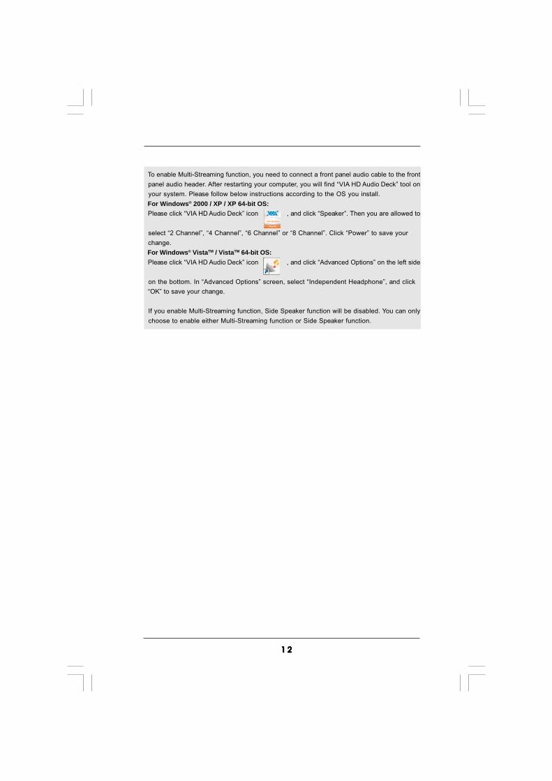
To enable Multi-Streaming function, you need to connect a front panel audio cable to the front panel audio header. After restarting your computer, you will find “VIA HD Audio Deck” tool on your system. Please follow below instructions according to the OS you install. For Windows® 2000 / XP / XP 64-bit OS: Please click “VIA HD Audio Deck” icon , and click “Speaker”. Then you are allowed to
select “2 Channel”, “4 Channel”, “6 Channel” or “8 Channel”. Click “Power” to save your change. For Windows® VistaTM / VistaTM 64-bit OS: Please click “VIA HD Audio Deck” icon , and click “Advanced Options” on the left side
on the bottom. In “Advanced Options” screen, select “Independent Headphone”, and click “OK” to save your change.
If you enable Multi-Streaming function, Side Speaker function will be disabled. You can only choose to enable either Multi-Streaming function or Side Speaker function.
1 31 31 31 31 3
Chapter 2: InstallationChapter 2: InstallationChapter 2: InstallationChapter 2: InstallationChapter 2: InstallationThis is an ATX form factor (12.0" x 8.0", 30.5 x 20.3 cm) motherboard. Before youinstall the motherboard, study the configuration of your chassis to ensure that themotherboard fits into it.
Make sure to unplug the power cord before installing or removing themotherboard. Failure to do so may cause physical injuries to you anddamages to motherboard components.
2.1 Screw Holes2.1 Screw Holes2.1 Screw Holes2.1 Screw Holes2.1 Screw HolesPlace screws into the holes indicated by circles to secure the motherboard to thechassis.
Do not over-tighten the screws! Doing so may damage the motherboard.
2.2 Pre-installation Precautions2.2 Pre-installation Precautions2.2 Pre-installation Precautions2.2 Pre-installation Precautions2.2 Pre-installation PrecautionsTake note of the following precautions before you install motherboard componentsor change any motherboard settings.
1. Unplug the power cord from the wall socket before touching any component.2. To avoid damaging the motherboard components due to static electricity, NEVER
place your motherboard directly on the carpet or the like. Also remember to usea grounded wrist strap or touch a safety grounded object before you handlecomponents.
3. Hold components by the edges and do not touch the ICs.4. Whenever you uninstall any component, place it on a grounded antistatic pad or
in the bag that comes with the component.
Before you install or remove any component, ensure that the power is switched off or the power cord is detached from the power supply. Failure to do so may cause severe damage to the motherboard, peripherals, and/or components.

1 41 41 41 41 4
2.3 CPU Installation2.3 CPU Installation2.3 CPU Installation2.3 CPU Installation2.3 CPU InstallationFor the installation of Intel 775-LAND CPU,please follow the steps below.
Before you insert the 775-LAND CPU into the socket, please check ifthe CPU surface is unclean or if there is any bent pin on the socket.Do not force to insert the CPU into the socket if above situation isfound. Otherwise, the CPU will be seriously damaged.
Step 1. Open the socket:Step 1-1. Disengaging the lever by depressing
down and out on the hook to clearretention tab.
Step 1-2. Rotate the load lever to fully open po-sition at approximately 135 degrees.
Step 1-3. Rotate the load plate to fully open po-sition at approximately 100 degrees.
Step 2. Insert the 775-LAND CPU:Step 2-1. Hold the CPU by the edges where are
marked with black lines.
Step 2-2. Orient the CPU with IHS (IntegratedHeat Sink) up. Locate Pin1 and the twoorientation key notches.
775-Pin Socket Overview
black line
black line
775-Pin Socket
Pin1alignment key alignment key
Pin1
orientationkey notch
orientationkey notch
775-LAND CPU

1 51 51 51 51 5
For proper inserting, please ensure to match the two orientation keynotches of the CPU with the two alignment keys of the socket.
Step 2-3. Carefully place the CPU into the socketby using a purely vertical motion.
Step 2-4. Verify that the CPU is within the socketand properly mated to the orient keys.
Step 3. Remove PnP Cap (Pick and Place Cap):Use your left hand index finger and thumb tosupport the load plate edge, engage PnP capwith right hand thumb and peel the cap from thesocket while pressing on center of PnP cap toassist in removal.
1. It is recommended to use the cap tab to handle and avoid kicking off the PnP cap.2. This cap must be placed if returning the motherboard for after service.
Step 4. Close the socket:Step 4-1. Rotate the load plate onto the IHS.Step 4-2. While pressing down lightly on load
plate, engage the load lever.Step 4-3. Secure load lever with load plate tab
under retention tab of load lever.
1 61 61 61 61 6
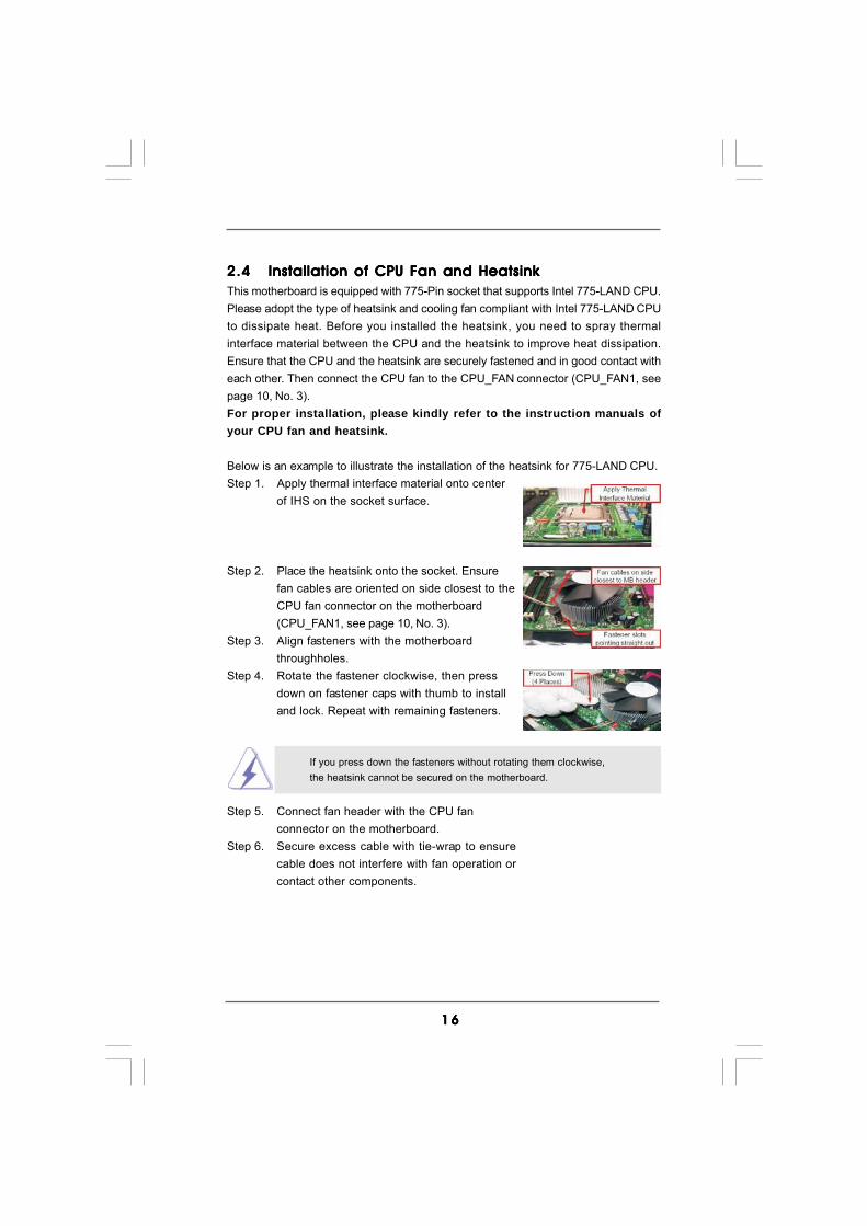
2.42.42.42.42.4 Installation of CPU Fan and HeatsinkInstallation of CPU Fan and HeatsinkInstallation of CPU Fan and HeatsinkInstallation of CPU Fan and HeatsinkInstallation of CPU Fan and HeatsinkThis motherboard is equipped with 775-Pin socket that supports Intel 775-LAND CPU.Please adopt the type of heatsink and cooling fan compliant with Intel 775-LAND CPUto dissipate heat. Before you installed the heatsink, you need to spray thermalinterface material between the CPU and the heatsink to improve heat dissipation.Ensure that the CPU and the heatsink are securely fastened and in good contact witheach other. Then connect the CPU fan to the CPU_FAN connector (CPU_FAN1, seepage 10, No. 3).For proper installation, please kindly refer to the instruction manuals ofyour CPU fan and heatsink.
Below is an example to illustrate the installation of the heatsink for 775-LAND CPU.Step 1. Apply thermal interface material onto center
of IHS on the socket surface.
Step 2. Place the heatsink onto the socket. Ensurefan cables are oriented on side closest to theCPU fan connector on the motherboard(CPU_FAN1, see page 10, No. 3).
Step 3. Align fasteners with the motherboardthroughholes.
Step 4. Rotate the fastener clockwise, then pressdown on fastener caps with thumb to installand lock. Repeat with remaining fasteners.
If you press down the fasteners without rotating them clockwise,the heatsink cannot be secured on the motherboard.
Step 5. Connect fan header with the CPU fanconnector on the motherboard.
Step 6. Secure excess cable with tie-wrap to ensurecable does not interfere with fan operation orcontact other components.

1 71 71 71 71 7
2.5 Installation of Memory Modules (DIMM)2.5 Installation of Memory Modules (DIMM)2.5 Installation of Memory Modules (DIMM)2.5 Installation of Memory Modules (DIMM)2.5 Installation of Memory Modules (DIMM)This motherboard provides four 240-pin DDR3 (Double Data Rate 3) DIMM slots,and supports Dual Channel Memory Technology. For dual channel configuration,you always need to install identical (the same brand, speed, size and chip-type) DDR3 DIMM pair in the slots of the same color. In other words, you have toinstall identical DDR3 DIMM pair in Dual Channel (DDR3_A1 and DDR3_B1;Blue slots; see p.10 No.5) or identical DDR3 DIMM pair in Dual Channel (DDR3_A2and DDR3_B2; white slots; see p.10 No.6), so that Dual Channel Memory Tech-nology can be activated. This motherboard also allows you to install four DDR3DIMMs for dual channel configuration, and please install identical DDR3 DIMMsin all four slots. You may refer to the Dual Channel Memory Configuration Tablebelow.
Dual Channel Memory Configurations
DDR3_A1 DDR3_A2 DDR3_B1 DDR3_B2(Blue Slot) (White Slot) (Blue Slot) (White Slot)
(1) Populated - Populated -(2) - Populated - Populated(3)* Populated Populated Populated Populated
* For the configuration (3), please install identical DDR3 DIMMs in all four
slots.
1. If you want to install two memory modules, for optimal compatibilityand reliability, it is recommended to install them in the slots of thesame color. In other words, install them either in the set of blue slots(DDR3_A1 and DDR3_B1), or in the set of white slots (DDR3_A2and DDR3_B2).
2. If only one memory module or three memory modules are installedin the DDR3 DIMM slots on this motherboard, it is unable to activatethe Dual Channel Memory Technology.
3. If a pair of memory modules is NOT installed in the same DualChannel, for example, installing a pair of memory modules inDDR3_A1 and DDR3_A2, it is unable to activate the Dual ChannelMemory Technology .
4. It is not allowed to install a DDR or DDR2 memory module intoDDR3 slot;otherwise, this motherboard and DIMM may be damaged.
5. If you adopt a DDR3 1600 memory module, you can only install it onDDR3_A1 slot.
1 81 81 81 81 8
notch
break
notchbreak
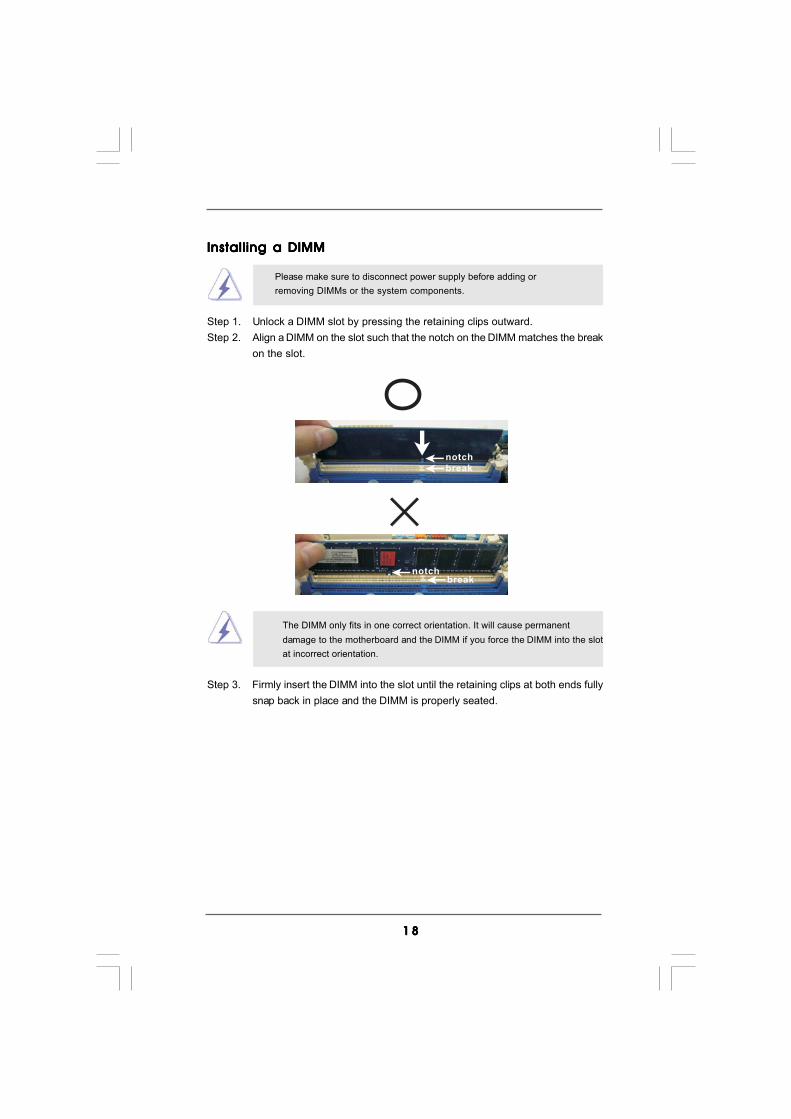
Installing a DIMMInstalling a DIMMInstalling a DIMMInstalling a DIMMInstalling a DIMM
Please make sure to disconnect power supply before adding orremoving DIMMs or the system components.
Step 1. Unlock a DIMM slot by pressing the retaining clips outward.Step 2. Align a DIMM on the slot such that the notch on the DIMM matches the break
on the slot.
The DIMM only fits in one correct orientation. It will cause permanentdamage to the motherboard and the DIMM if you force the DIMM into the slotat incorrect orientation.
Step 3. Firmly insert the DIMM into the slot until the retaining clips at both ends fullysnap back in place and the DIMM is properly seated.
1 91 91 91 91 9
2.6 Expansion Slots (PCI and PCI Express Slots)2.6 Expansion Slots (PCI and PCI Express Slots)2.6 Expansion Slots (PCI and PCI Express Slots)2.6 Expansion Slots (PCI and PCI Express Slots)2.6 Expansion Slots (PCI and PCI Express Slots)There are 2 PCI slots and 4 PCI Express slots on this motherboard.PCI Slots: PCI slots are used to install expansion cards that have the 32-bit PCI
interface.PCIE Slots:
PCIE1 / PCIE2 / PCIE4 (PCIE x1 slot; White) is used for PCI Expresscards with x1 lane width cards, such as Gigabit LAN card, SATA2card, etc.PCIE3 (PCIE x16 slot; Blue) is used for PCI Express x16 lane widthgraphics cards.
Installing an expansion cardInstalling an expansion cardInstalling an expansion cardInstalling an expansion cardInstalling an expansion cardStep 1. Before installing the expansion card, please make sure that the power
supply is switched off or the power cord is unplugged. Please read thedocumentation of the expansion card and make necessary hardwaresettings for the card before you start the installation.
Step 2. Remove the system unit cover (if your motherboard is already installed in achassis).
Step 3. Remove the bracket facing the slot that you intend to use. Keep the screwsfor later use.
Step 4. Align the card connector with the slot and press firmly until the card iscompletely seated on the slot.
Step 5. Fasten the card to the chassis with screws.Step 6. Replace the system cover.
2 02 02 02 02 0
+5V
1_2
+5VSB
2_3
Clear CMOS
2_31_2
Default
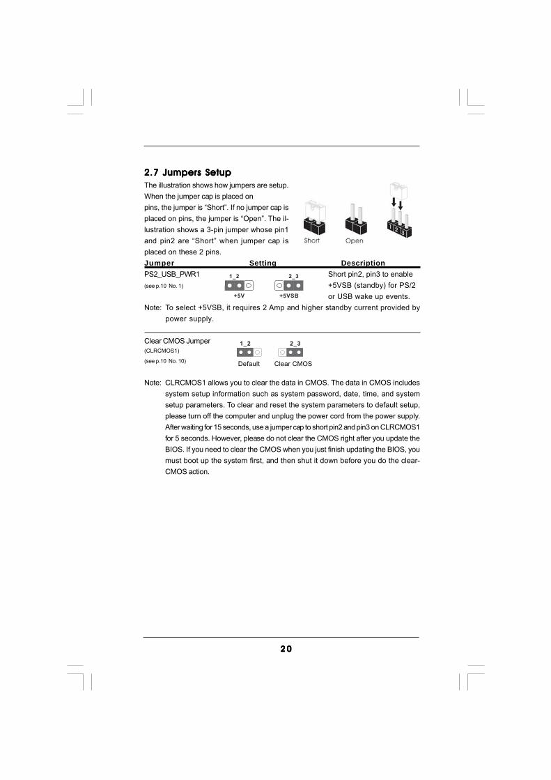
2.7 Jumpers Setup2.7 Jumpers Setup2.7 Jumpers Setup2.7 Jumpers Setup2.7 Jumpers SetupThe illustration shows how jumpers are setup.When the jumper cap is placed onpins, the jumper is “Short”. If no jumper cap isplaced on pins, the jumper is “Open”. The il-lustration shows a 3-pin jumper whose pin1and pin2 are “Short” when jumper cap isplaced on these 2 pins.Jumper Setting DescriptionPS2_USB_PWR1 Short pin2, pin3 to enable(see p.10 No. 1) +5VSB (standby) for PS/2
or USB wake up events.Note: To select +5VSB, it requires 2 Amp and higher standby current provided by
power supply.
Clear CMOS Jumper(CLRCMOS1)
(see p.10 No. 10)
Note: CLRCMOS1 allows you to clear the data in CMOS. The data in CMOS includessystem setup information such as system password, date, time, and systemsetup parameters. To clear and reset the system parameters to default setup,please turn off the computer and unplug the power cord from the power supply.After waiting for 15 seconds, use a jumper cap to short pin2 and pin3 on CLRCMOS1for 5 seconds. However, please do not clear the CMOS right after you update theBIOS. If you need to clear the CMOS when you just finish updating the BIOS, youmust boot up the system first, and then shut it down before you do the clear-CMOS action.

2 12 12 12 12 1
FLOPPY1Pin1
the red-striped side toPin1
2.8 Onboard Headers and Connectors2.8 Onboard Headers and Connectors2.8 Onboard Headers and Connectors2.8 Onboard Headers and Connectors2.8 Onboard Headers and Connectors
Onboard headers and connectors are NOT jumpers. Do NOT placejumper caps over these headers and connectors. Placing jumpercaps over the headers and connectors will cause permanent dam-age of the motherboard!
FDD connector(33-pin FLOPPY1)
(see p.10 No. 26)
Note: Make sure the red-striped side of the cable is plugged into Pin1 side of theconnector.
Primary IDE connector (Blue)(39-pin IDE1, see p.10 No. 9)
Note: Please refer to the instruction of your IDE device vendor for the details.
Serial ATAII Connectors These six Serial ATAII (SATAII)(SATAII_1 (Port 0): connectors support SATA datasee p.10, No. 13) cables for internal storage(SATAII_2 (Port 1): devices. The current SATAIIsee p.10, No. 14) interface allows up to 3.0 Gb/s(SATAII_3 (Port 2): data transfer rate.see p.10, No. 15)(SATAII_4 (Port 3):see p.10, No. 16)(SATAII_5 (Port 4):see p.10, No. 18)(SATAII_6 (Port 5):see p.10, No. 17)
connect the black endto the IDE devices
connect the blue endto the motherboard
IDE1PIN1
80-conductor ATA 66/100/133 cable
Serial ATA (SATA) Either end of the SATA data cableData Cable can be connected to the SATA /(Optional) SATAII hard disk or the SATAII
connector on this motherboard.
SATA
II_5
(Por
t 4)
SAT
AII_
3 (P
ort 2
) S
ATAI
I_1
(Por
t 0)
SATA
II_6
(Por
t 5)
SAT
AII_
4 (P
ort 3
) S
ATAI
I_2
(Por
t 1)
2 22 22 22 22 2
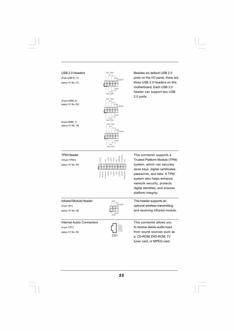
USB 2.0 Headers Besides six default USB 2.0(9-pin USB10_11) ports on the I/O panel, there are(see p.10 No. 21) three USB 2.0 headers on this
motherboard. Each USB 2.0header can support two USB2.0 ports.
(9-pin USB8_9)(see p.10 No. 20)
(9-pin USB6_7)(see p.10 No. 19)
Infrared Module Header This header supports an(5-pin IR1) optional wireless transmitting(see p.10 No. 28) and receiving infrared module.
DUMMY
GND
+5VIRTX
IRRX
1
1
USB_PWR
P-8
GND
DUMMY
USB_PWR
P+8
GND
P-9P+9
1
USB_PWRP-10
GND
DUMMY
USB_PWR
P+10
GND
P-11P+11
USB_PWR
USB_PWR
P+7P-7
P+6P-6
GND
GND
DUMMY
1
TPM Header This connector supports a(19-pin TPM1) Trusted Platform Module (TPM)(see p.10 No. 24) system, which can securely
store keys, digital certificates,passwords, and data. A TPMsystem also helps enhancenetwork security, protectsdigital identities, and ensuresplatform integrity.
1
GN
D
NC
LA
D2
LA
D1
GN
D
NC
SE
RIR
Q
CLK
RU
N
NC
PC
ICLK
PC
IRST#
LA
D3
+3
V
LA
D0
NC
+3
VSB
GN
D
PW
RD
WN
FR
AM
E
Internal Audio Connectors This connector allows you(4-pin CD1) to receive stereo audio input(see p.10 No. 35) from sound sources such as
a CD-ROM, DVD-ROM, TVtuner card, or MPEG card.
CD-L
GNDGND
CD-R
CD1

2 32 32 32 32 3
GND
PWRBTN#PLED-
PLED+
DUMMYRESET#
GND
HDLED+HDLED-
1
System Panel Header This header accommodates(9-pin PANEL1) several system front panel(see p.10 No. 22) functions.
+5V
DUMMYDUMMY
SPEAKER
1Chassis Speaker Header Please connect the chassis(4-pin SPEAKER 1) speaker to this header.(see p.10 No. 23)
Chassis and Power Fan Connectors Please connect the fan cables(3-pin CHA_FAN1) to the fan connectors and(see p.10 No. 8) match the black wire to the
ground pin.(3-pin PWR_FAN1)
(see p.10 No. 36)
1. High Definition Audio supports Jack Sensing, but the panel wire on the chassis must support HDA to function correctly. Please follow the
instruction in our manual and chassis manual to install your system.2. If you use AC’97 audio panel, please install it to the front panel audio header as below: A. Connect Mic_IN (MIC) to MIC2_L. B. Connect Audio_R (RIN) to OUT2_R and Audio_L (LIN) to OUT2_L.
C. Connect Ground (GND) to Ground (GND). D. MIC_RET and OUT_RET are for HD audio panel only. You don’t need to connect them for AC’97 audio panel. E. Enter BIOS Setup Utility. Enter Advanced Settings, and then select
Chipset Configuration. Set the Front Panel Control option from [Auto] to [Enabled].
GND
+12V
PWR_FAN_SPEED
GND
+12V
CHA_FAN_SPEED
J_SENSE
OUT2_L
1
MIC_RETPRESENCE#
GND
OUT2_R
MIC2_R
MIC2_L
OUT_RET
Front Panel Audio Header This is an interface for front(9-pin HD_AUDIO1) panel audio cable that allows(see p.10 No. 32) convenient connection and
control of audio devices.

2 42 42 42 42 4
Serial port Header This COM1 header supports a(9-pin COM1) serial port module.(see p.10 No. 25)
CCTS#1DDSR#1
DDTR#1RRXD1
DDCD#1TTXD1
GNDRRTS#1
RRI#1
1
ATX Power Connector Please connect an ATX power(24-pin ATXPWR1) supply to this connector.(see p.10 No. 7)
20-Pin ATX Power Supply Installation
Though this motherboard provides 24-pin ATX power connector, it can still work if you adopt a traditional 20-pin ATX power supply. To use the 20-pin ATX power supply, please plug your power supply along with Pin 1 and Pin 13.
12
1
24
13
12
1
24
13
ATX 12V Power Connector Please connect an ATX 12V(8-pin ATX12V1) power supply to this connector.(see p.10 No. 2)
Though this motherboard provides 4-Pin CPU fan (Quiet Fan) support, the 3-Pin CPU fan still can work successfully even without the fan speed control function. If you plan to connect the 3-Pin CPU fan to the CPU fan connector on this motherboard, please connect it to Pin 1-3.
3-Pin Fan Installation
Pin 1-3 Connected
CPU Fan Connector Please connect a CPU fan cable(4-pin CPU_FAN1) to this connector and match(see p.10, No. 3) the black wire to the ground pin.
4-Pin ATX 12V Power Supply Installation
Though this motherboard provides 8-pin ATX 12V power connector, it can stillwork if you adopt a traditional 4-pin ATX 12V power supply. To use the 4-pinATX power supply, please plug your power supply along withPin 1 and Pin 5.
8 5
4 1
8 5
4 1
1 2 3 4

2 52 52 52 52 5
1
GND
+5VSPDIFOUT
HDMI_SPDIF Header HDMI_SPDIF header, providing(3-pin HDMI_SPDIF1) SPDIF audio output to HDMI VGA(see p.10 No. 27) card, allows the system to
connect HDMI Digital TV/projector/LCD devices. Pleaseconnect the HDMI_SPDIFconnector of HDMI VGA card tothis header.
HDMI_SPDIF Cable Please connect the black end (A)(Optional) of HDMI_SPDIF cable to the
HDMI_SPDIF header on themotherboard. Then connect thewhite end (B or C) ofHDMI_SPDIF cable to theHDMI_SPDIF connector of HDMIVGA card.
A. black end B. white end (2-pin) C. white end (3-pin)
CB
GND
+5V
SPDIFOUT blue
black
blue
blackGND
SPDIFOUT blue
blackGND
SPDIFOUT
A
2 62 62 62 62 6
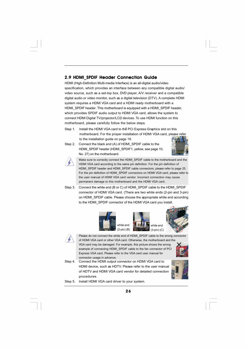
2.9 HDMI_SPDIF Header Connection Guide2.9 HDMI_SPDIF Header Connection Guide2.9 HDMI_SPDIF Header Connection Guide2.9 HDMI_SPDIF Header Connection Guide2.9 HDMI_SPDIF Header Connection GuideHDMI (High-Definition Multi-media Interface) is an all-digital audio/videospecification, which provides an interface between any compatible digital audio/video source, such as a set-top box, DVD player, A/V receiver and a compatibledigital audio or video monitor, such as a digital television (DTV). A complete HDMIsystem requires a HDMI VGA card and a HDMI ready motherboard with aHDMI_SPDIF header. This motherboard is equipped with a HDMI_SPDIF header,which provides SPDIF audio output to HDMI VGA card, allows the system toconnect HDMI Digital TV/projector/LCD devices. To use HDMI function on thismotherboard, please carefully follow the below steps.
•
Make sure to correctly connect the HDMI_SPDIF cable to the motherboard and theHDMI VGA card according to the same pin definition. For the pin definition ofHDMI_SPDIF header and HDMI_SPDIF cable connectors, please refer to page 25.For the pin definition of HDMI_SPDIF connectors on HDMI VGA card, please refer tothe user manual of HDMI VGA card vendor. Incorrect connection may causepermanent damage to this motherboard and the HDMI VGA card.
white end(2-pin) (B)
white end(3-pin) (C)
Please do not connect the white end of HDMI_SPDIF cable to the wrong connectorof HDMI VGA card or other VGA card. Otherwise, the motherboard and theVGA card may be damaged. For example, this picture shows the wrongexample of connecting HDMI_SPDIF cable to the fan connector of PCIExpress VGA card. Please refer to the VGA card user manual forconnector usage in advance.
Step 4. Connect the HDMI output connector on HDMI VGA card toHDMI device, such as HDTV. Please refer to the user manualof HDTV and HDMI VGA card vendor for detailed connectionprocedures.
Step 5. Install HDMI VGA card driver to your system.
Step 3. Connect the white end (B or C) of HDMI_SPDIF cable to the HDMI_SPDIFconnector of HDMI VGA card. (There are two white ends (2-pin and 3-pin)on HDMI_SPDIF cable. Please choose the appropriate white end accordingto the HDMI_SPDIF connector of the HDMI VGA card you install.
Step 1. Install the HDMI VGA card to the PCI Express Graphics slot on this motherboard. For the proper installation of HDMI VGA card, please refer to the installation guide on page 19.
Step 2. Connect the black end (A) of HDMI_SPDIF cable to theHDMI_SPDIF header (HDMI_SPDIF1, yellow, see page 10,No. 27) on the motherboard.

2 72 72 72 72 7
2.10 SA2.10 SA2.10 SA2.10 SA2.10 SATTTTTAII Hard Disk Setup GuideAII Hard Disk Setup GuideAII Hard Disk Setup GuideAII Hard Disk Setup GuideAII Hard Disk Setup GuideBefore installing SATAII hard disk to your computer, please carefully read belowSATAII hard disk setup guide. Some default setting of SATAII hard disks may not beat SATAII mode, which operate with the best performance. In order to enable SATAIIfunction, please follow the below instruction with different vendors to correctly adjustyour SATAII hard disk to SATAII mode in advance; otherwise, your
SATAII hard disk may fail to run at SATAII mode.
Western Digital
If pin 5 and pin 6 are shorted, SATA 1.5Gb/s will be enabled.On the other hand, if you want to enable SATAII 3.0Gb/s, please remove thejumpers from pin 5 and pin 6.
SAMSUNG
If pin 3 and pin 4 are shorted, SATA 1.5Gb/s will be enabled.On the other hand, if you want to enable SATAII 3.0Gb/s, please remove thejumpers from pin 3 and pin 4.
HITACHIPlease use the Feature Tool, a DOS-bootable tool, for changing various ATAfeatures. Please visit HITACHI’s website for details:http://www.hitachigst.com/hdd/support/download.htm
1357
2468
1357
2468
The above examples are just for your reference. For different SATAII hard disk products of different vendors, the jumper pin setting methods may
not be the same. Please visit the vendors’ website for the updates.

2 82 82 82 82 8
2.112.112.112.112.11 Serial ASerial ASerial ASerial ASerial ATTTTTA (SAA (SAA (SAA (SAA (SATTTTTA) / Serial AA) / Serial AA) / Serial AA) / Serial AA) / Serial ATTTTTAII (SAAII (SAAII (SAAII (SAAII (SATTTTTAII) Hard DisksAII) Hard DisksAII) Hard DisksAII) Hard DisksAII) Hard Disks
InstallationInstallationInstallationInstallationInstallationP43DE3 adopts Intel® ICH10 south bridge chipset that supports Serial ATA (SATA)/ Serial ATAII (SATAII) hard disks. You may install SATA / SATAII hard disks on thismotherboard for internal storage devices. This section will guide you to install theSATA / SATAII hard disks.
STEP 1: Install the SATA / SATAII hard disks into the drive bays of your chassis.STEP 2: Connect the SATA power cable to the SATA / SATAII hard disk.STEP 3: Connect one end of the SATA data cable to the motherboard’s SATAII
connector.STEP 4: Connect the other end of the SATA data cable to the SATA / SATAII hard
disk.
It is not recommended to switch the “Configure SATAII as” setting afterOS installation.
2.12 Hot Plug F2.12 Hot Plug F2.12 Hot Plug F2.12 Hot Plug F2.12 Hot Plug Function for SAunction for SAunction for SAunction for SAunction for SATTTTTA / SAA / SAA / SAA / SAA / SATTTTTAII HDDsAII HDDsAII HDDsAII HDDsAII HDDsP43DE3 supports Hot Plug function for SATA / SATAII Devices in AHCI mode. Intel®
ICH10 south bridge chipset provides hardware support for Advanced Host controllerInterface (AHCI), a new programming interface for SATA host controllers developed thrua joint industry effort.
NOTEWhat is Hot Plug Function?If the SATA / SATAII HDDs are NOT set for RAID configuration, it is called“Hot Plug” for the action to insert and remove the SATA / SATAII HDDswhile the system is still power-on and in working condition.However, please note that it cannot perform Hot Plug if the OS has beeninstalled into the SATA / SATAII HDD.

2 92 92 92 92 9
Caution1. Without SATA 15-pin power connector interface, the SATA / SATAII Hot Plug cannot be processed.2. Even some SATA / SATAII HDDs provide both SATA 15-pin power connector and IDE 1x4-pin conventional power connector interfaces, the IDE 1x4-pin conventional power connector interface is definitely not able to support Hot Plug and will cause the HDD damage and data loss.
SATA 7-pinconnector
1x4-pin conventionalpower connector (White)connect to power supply
A. SATA data cable (Red) B. SATA power cable
2.13 SA2.13 SA2.13 SA2.13 SA2.13 SATTTTTA / SAA / SAA / SAA / SAA / SATTTTTAII HDD Hot Plug FAII HDD Hot Plug FAII HDD Hot Plug FAII HDD Hot Plug FAII HDD Hot Plug Feature and Operationeature and Operationeature and Operationeature and Operationeature and Operation
GuideGuideGuideGuideGuideThis motherboard supports Hot Plug feature for SATA / SATAII HDD in AHCI mode.Please read below operation guide of SATA / SATAII HDD Hot Plug feature carefully.Before you process the SATA / SATAII HDD Hot Plug, please check below cableaccessories from the motherboard gift box pack.A. 7-pin SATA data cableB. SATA power cable with SATA 15-pin power connector interface
The SATA 15-pin powerconnector (Black) connectto SATA / SATAII HDD
Points of attention, before you process the Hot Plug:1. Below operation procedure is designed only for our motherboard, which supports SATA / SATAII HDD Hot Plug. * The SATA / SATAII Hot Plug feature might not be supported by the chipset because of its limitation, the SATA / SATAII Hot Plug support information of our motherboard is indicated in the product spec on our website: www.asrock.com2. Make sure your SATA / SATAII HDD can support Hot Plug function from your dealer or HDD user manual. The SATA / SATAII HDD, which cannot support Hot Plug function, will be damaged under the Hot Plug operation.3. Please make sure the SATA / SATAII driver is installed into system properly. The latest SATA / SATAII driver is available on our support website: www.asrock.com4. Make sure to use the SATA power cable & data cable, which are from our motherboard package.5. Please follow below instructions step by step to reduce the risk of HDD crash or data loss.
3 03 03 03 03 0
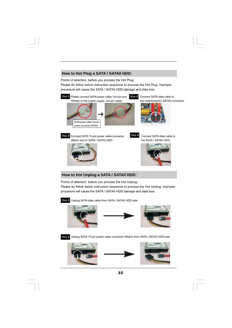
How to Hot Plug a SATA / SATAII HDD:Points of attention, before you process the Hot Plug:Please do follow below instruction sequence to process the Hot Plug, improperprocedure will cause the SATA / SATAII HDD damage and data loss.
Connect SATA data cable tothe motherboard’s SATAII connector.
Connect SATA 15-pin power cable connector(Black) end to SATA / SATAII HDD.
Connect SATA data cable tothe SATA / SATAII HDD.
How to Hot Unplug a SATA / SATAII HDD:
Points of attention, before you process the Hot Unplug:Please do follow below instruction sequence to process the Hot Unplug, improperprocedure will cause the SATA / SATAII HDD damage and data loss.
Please connect SATA power cable 1x4-pin end(White) to the power supply 1x4-pin cable.
Step 1 Step 2
Step 3 Step 4
Step 2
SATA power cable 1x4-pinpower connector (White)
Unplug SATA data cable from SATA / SATAII HDD side.
Unplug SATA 15-pin power cable connector (Black) from SATA / SATAII HDD side.
Step 1
3 13 13 13 13 1
2.152.152.152.152.15 Installing WindowsInstalling WindowsInstalling WindowsInstalling WindowsInstalling Windows®®®®® 2000 / XP / XP 64-bit / Vista 2000 / XP / XP 64-bit / Vista 2000 / XP / XP 64-bit / Vista 2000 / XP / XP 64-bit / Vista 2000 / XP / XP 64-bit / VistaTM TM TM TM TM /////
VistaVistaVistaVistaVistaTMTMTMTMTM 64-bit W 64-bit W 64-bit W 64-bit W 64-bit Without RAID Fithout RAID Fithout RAID Fithout RAID Fithout RAID FunctionsunctionsunctionsunctionsunctionsIf you want to install Windows® 2000 / XP / XP 64-bit / VistaTM / VistaTM 64-bit OSon your SATA / SATAII HDDs without RAID functions, please follow belowprocedures according to the OS you install.
2.15.1 Installing Windows2.15.1 Installing Windows2.15.1 Installing Windows2.15.1 Installing Windows2.15.1 Installing Windows®®®®® 2000 / XP / XP 64-bit 2000 / XP / XP 64-bit 2000 / XP / XP 64-bit 2000 / XP / XP 64-bit 2000 / XP / XP 64-bit
W W W W Without RAID Fithout RAID Fithout RAID Fithout RAID Fithout RAID FunctionsunctionsunctionsunctionsunctionsIf you want to install Windows® 2000 / XP / XP 64-bit OS on your SATA / SATAII HDDswithout RAID functions, please follow below steps.
Using SATA / SATAII HDDs with NCQ function
Since Windows® 2000 AHCI driver is not provided by the chipset vendor,AHCI function is not supported under Windows® 2000.
2.142.142.142.142.14 Driver Installation Guide Driver Installation Guide Driver Installation Guide Driver Installation Guide Driver Installation GuideTo install the drivers to your system, please insert the support CD to your optical drivefirst. Then, the drivers compatible to your system can be auto-detected and listed onthe support CD driver page. Please follow the order from up to bottom side to installthose required drivers. Therefore, the drivers you install can work properly.
STEP 1: Set Up BIOS.A. Enter BIOS SETUP UTILITY Advanced screen Storage Configuration.B. Set “SATAII Configuration” to [Enhanced], and then in the option “Configure SATAII as”, please set the option to [AHCI].STEP 2: Make a SATA / SATAII driver diskette.A. Insert the Support CD into your optical drive to boot your system.B. During POST at the beginning of system boot-up, press <F11> key, and then a window for boot devices selection appears. Please select CD-ROM as the boot device.C. When you see the message on the screen, “Do you want to generate Serial ATA driver diskette [YN]?”, press <Y>.D. Then you will see these messages,
Please insert a diskette into the floppy drive.WARNING! Formatting the floppy diskette willlose ALL data in it!Start to format and copy files [YN]?Please insert a floppy diskette into the floppy drive, and press <Y>.
E. The system will start to format the floppy diskette and copy SATA / SATAII drivers into the floppy diskette.
3 23 23 23 23 2
STEP 3: Install Windows® XP / XP 64-bit OS on your system. (Windows® 2000 is not supported.)After making a SATA / SATAII driver diskette, you can start to install Windows® XP / XP64-bit on your system. At the beginning of Windows® setup, press F6 to install a third-party AHCI driver. When prompted, insert the SATA / SATAII driver diskette containingthe Intel® AHCI driver. After reading the floppy disk, the driver will be presented. Selectthe driver to install according to the mode you choose and the OS you install. You mayselect: "Intel(R) ICH10 SATA AHCI Controller (Desktop - Windows XP)" for Windows® XPor "Intel(R) ICH10 SATA AHCI Controller (Desktop - Windows XP64)" for Windows® XP64-bit.
STEP 1: Set up BIOS.A. Enter BIOS SETUP UTILITY Advanced screen Storage Configuration.B. Set “SATAII Configuration” to [Enhanced], and then in the option “Configure SATAII as”, please set the option to [IDE].STEP 2: Install Windows® 2000 / XP / XP 64-bit OS on your system.
Using SATA / SATAII HDDs without NCQ function
2.15.2 Installing Windows2.15.2 Installing Windows2.15.2 Installing Windows2.15.2 Installing Windows2.15.2 Installing Windows®®®®® Vista Vista Vista Vista VistaTM TM TM TM TM / Vista/ Vista/ Vista/ Vista/ VistaTMTMTMTMTM 64-bit 64-bit 64-bit 64-bit 64-bit
W W W W Without RAID Fithout RAID Fithout RAID Fithout RAID Fithout RAID FunctionsunctionsunctionsunctionsunctionsIf you want to install Windows® VistaTM / VistaTM 64-bit OS on your SATA / SATAIIHDDs without RAID functions, please follow below steps.
Using SATA / SATAII HDDs with NCQ function
STEP 1: Set Up BIOS.A. Enter BIOS SETUP UTILITY Advanced screen Storage Configuration.B. Set “SATAII Configuration” to [Enhanced], and then in the option “Configure SATAII as”, please set the option to [AHCI].STEP 2: Install Windows® VistaTM / VistaTM 64-bit OS on your system.Insert the Windows® VistaTM / VistaTM 64-bit optical disk into the optical drive to bootyour system, and follow the instruction to install Windows® VistaTM / VistaTM 64-bit OSon your system. When you see “Where do you want to install Windows?” page, pleaseinsert the ASRock Support CD into your optical drive, and click the “Load Driver” buttonon the left on the bottom to load the Intel® AHCI drivers. Intel® AHCI drivers are in thefollowing path in our Support CD:.. \ I386 (For Windows® VistaTM OS).. \ AMD64 (For Windows® VistaTM 64-bit OS)After that, please insert Windows® VistaTM / VistaTM 64-bit optical disk into the opticaldrive again to continue the installation.

3 33 33 33 33 3
2.162.162.162.162.16 Untied Overclocking TUntied Overclocking TUntied Overclocking TUntied Overclocking TUntied Overclocking TechnologyechnologyechnologyechnologyechnologyThis motherboard supports Untied Overclocking Technology, which means duringoverclocking, FSB enjoys better margin due to fixed PCI / PCIE buses. Before youenable Untied Overclocking function, please enter “Overclock Mode” option ofBIOS setup to set the selection from [Auto] to [Manual]. Therefore, CPU FSB isuntied during overclocking, but PCI / PCIE buses are in the fixed mode so that FSBcan operate under a more stable overclocking environment.
Please refer to the warning on page 8 for the possible overclocking riskbefore you apply Untied Overclocking Technology.
Using SATA / SATAII HDDs without NCQ function
STEP 1: Set up BIOS.A. Enter BIOS SETUP UTILITY Advanced screen Storage Configuration.B. Set “SATAII Configuration” to [Enhanced], and then in the option “Configure SATAII as”, please set the option to [IDE].STEP 2: Install Windows® VistaTM / VistaTM 64-bit OS on your system.

3 43 43 43 43 4
Chapter 3: BIOS SETUP UTILITYChapter 3: BIOS SETUP UTILITYChapter 3: BIOS SETUP UTILITYChapter 3: BIOS SETUP UTILITYChapter 3: BIOS SETUP UTILITY3.13.13.13.13.1 IntroductionIntroductionIntroductionIntroductionIntroductionThis section explains how to use the BIOS SETUP UTILITY to configure your system.The BIOS FWH chip on the motherboard stores the BIOS SETUP UTILITY. You mayrun the BIOS SETUP UTILITY when you start up the computer. Please press <F2> or<Del> during the Power-On-Self-Test (POST) to enter the BIOS SETUP UTILITY,otherwise, POST will continue with its test routines.If you wish to enter the BIOS SETUP UTILITY after POST, restart the system bypressing <Ctl> + <Alt> + <Delete>, or by pressing the reset button on the systemchassis. You may also restart by turning the system off and then back on.
Because the BIOS software is constantly being updated, thefollowing BIOS setup screens and descriptions are for refer-ence purpose only, and they may not exactly match what yousee on your screen.
3.1.13.1.13.1.13.1.13.1.1 BIOS Menu BarBIOS Menu BarBIOS Menu BarBIOS Menu BarBIOS Menu BarThe top of the screen has a menu bar with the following selections:Main To set up the system time/date informationOC Tweaker To set up overclocking featuresAdvanced To set up the advanced BIOS featuresH/W Monitor To display current hardware statusBoot To set up the default system device to locate and load the
Operating SystemSecurity To set up the security featuresExit To exit the current screen or the BIOS SETUP UTILITYUse < > key or < > key to choose among the selections on the menu bar,and then press <Enter> to get into the sub screen.

3 53 53 53 53 5
BIOS SETUP UTILITY
Main OC Tweaker H/W Monitor Boot Security ExitAdvanced
System Overview
System TimeSystem Date
[ :00:09][Wed 07/29/2009]
Use [Enter], [TAB]or [SHIFT-TAB] toselect a field.
Use [+] or [-] toconfigure system Time.
Select ScreenSelect Item
+- Change FieldTab Select FieldF1 General HelpF9 Load DefaultsF10 Save and ExitESC Exit
BIOS VersionProcessor Type
Processor SpeedMicrocode Update
Total Memory
Cache Size
DDR3_A1DDR3_A2DDR3_B1DDR3_B2
: P43DE3 P1.00: Intel (R) Core (TM) 2 Duo CPU
E8400 @ 3.00GHz (64bit): 4400MHz
: 6144KB: 1067A/A07
: 2048MBSingle-Channel Memory Mode
: 2048MB/550MHz (DDR3 1100): None: None: None
v02.54 (C) Copyright 1985-2005, American Megatrends, Inc.
14
3.1.23.1.23.1.23.1.23.1.2 Navigation KeysNavigation KeysNavigation KeysNavigation KeysNavigation KeysPlease check the following table for the function description of each navigation key.
Navigation Key(s) Function Description / Moves cursor left or right to select Screens / Moves cursor up or down to select items + / - To change option for the selected items<Enter> To bring up the selected screen<F1> To display the General Help Screen<F9> To load optimal default values for all the settings<F10> To save changes and exit the BIOS SETUP UTILITY<ESC> To jump to the Exit Screen or exit the current screen
3.23 .23 .23 .23 .2 Main ScreenMain ScreenMain ScreenMain ScreenMain ScreenWhen you enter the BIOS SETUP UTILITY, the Main screen will appear and display thesystem overview.
System Time [Hour:Minute:Second]Use this item to specify the system time.
System Date [Day Month/Date/Year]Use this item to specify the system date.
3 63 63 63 63 6
BIOS SETUP UTILITY
Main Advanced H/W Monitor Boot Security Exit
Overclocking may causedamage to your CPU andmotherboard.It should be done atyour own risk andexpense.
Select ScreenSelect Item
Enter Go to Sub ScreenF1 General HelpF9 Load DefaultsF10 Save and ExitESC Exit
v02.54 (C) Copyright 1985-2005, American Megatrends, Inc.
OC Tweaker
OC Tweaker Settings
Load CPU EZ OC Setting [Press Enter]
CPU Frequency (MHz)PCIE Frequency (MHz)
Overclock Mode[133][100]
[Auto]
Strap FSB to MCHBoot Failure GuardSpread Spectrum
[Auto][Enabled][Auto]
Ratio CMOS Setting [9]
DRAM Timing ConfigurationDRAM RCOMP and tRD ConfigurationDRAM DLL SKEW ConfigurationVoltage Configuration
Ratio Actual Value [8]
DRAM FrequencyDRAM Command Rate
[Auto][Auto]
ASRock VDrop Control [With VDrop]
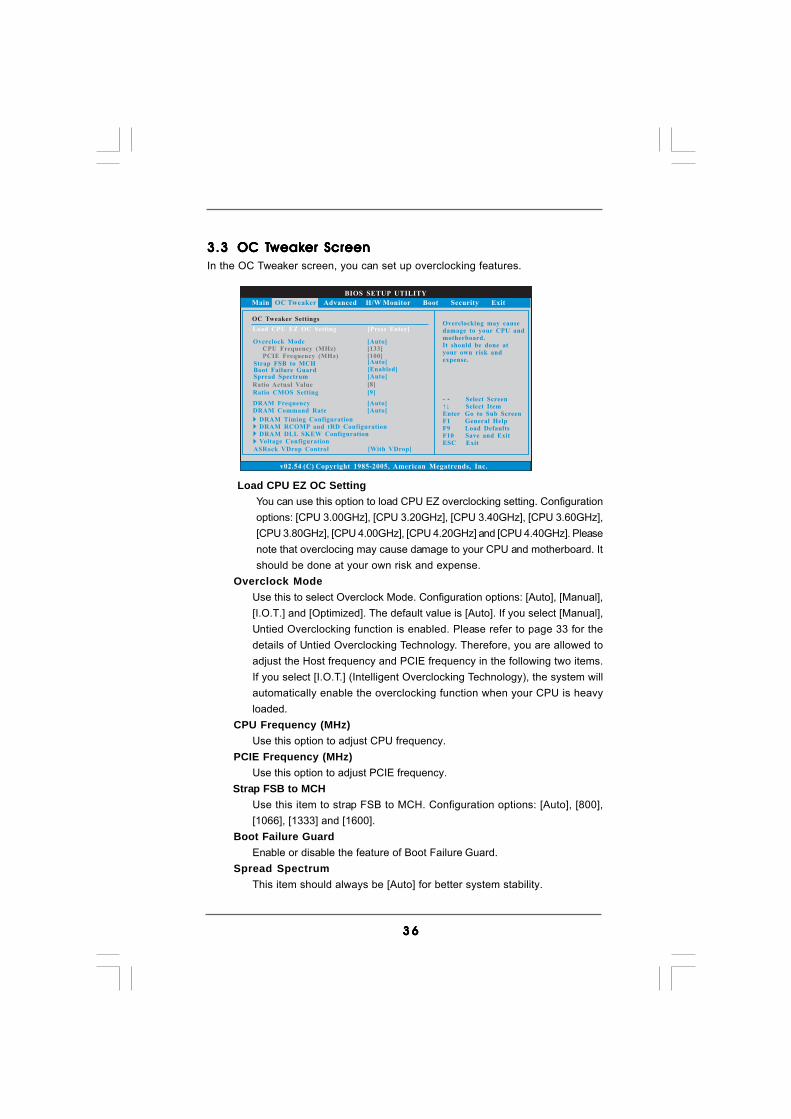
3.33.33.33.33.3 OC TOC TOC TOC TOC Tweakweakweakweakweaker Screener Screener Screener Screener ScreenIn the OC Tweaker screen, you can set up overclocking features.
Load CPU EZ OC SettingYou can use this option to load CPU EZ overclocking setting. Configurationoptions: [CPU 3.00GHz], [CPU 3.20GHz], [CPU 3.40GHz], [CPU 3.60GHz],[CPU 3.80GHz], [CPU 4.00GHz], [CPU 4.20GHz] and [CPU 4.40GHz]. Pleasenote that overclocing may cause damage to your CPU and motherboard. Itshould be done at your own risk and expense.
Overclock ModeUse this to select Overclock Mode. Configuration options: [Auto], [Manual],[I.O.T.] and [Optimized]. The default value is [Auto]. If you select [Manual],Untied Overclocking function is enabled. Please refer to page 33 for thedetails of Untied Overclocking Technology. Therefore, you are allowed toadjust the Host frequency and PCIE frequency in the following two items.If you select [I.O.T.] (Intelligent Overclocking Technology), the system willautomatically enable the overclocking function when your CPU is heavyloaded.
CPU Frequency (MHz)Use this option to adjust CPU frequency.
PCIE Frequency (MHz)Use this option to adjust PCIE frequency.
Strap FSB to MCHUse this item to strap FSB to MCH. Configuration options: [Auto], [800],[1066], [1333] and [1600].
Boot Failure GuardEnable or disable the feature of Boot Failure Guard.
Spread SpectrumThis item should always be [Auto] for better system stability.

3 73 73 73 73 7
Ratio Actual ValueThis is a read-only item, which displays the ratio actual value of thismotherboard.
Ratio CMOS SettingIf the ratio status is unlocked, you will find this item appear to allow youchanging the ratio value of this motherboard.
DRAM FrequencyIf [Auto] is selected, the motherboard will detect the memory module(s)inserted and assigns appropriate frequency automatically. You may select[Auto], [533MHz (DDR3 1066)], [667MHz (DDR3 1333)] or[800MHz (DDR3 1600)].
DRAM Command RateUse this item to adjust DRAM Command Rate. Configurationoptions : [1N], [2N] and [Auto].
3 83 83 83 83 8
BIOS SETUP UTILITY
Standard Memory Settings
Select ScreenSelect Item
+- Change OptionF1 General HelpF9 Load DefaultsF10 Save and ExitESC Exit
v02.54 (C) Copyright 1985-2005, American Megatrends, Inc.
OC Tweaker
Select ScreenSelect Item
+- Change OptionF1 General HelpF9 Load DefaultsF10 Save and ExitESC Exit
XMP Technology [Auto]
DRAM tCLDRAM tRCDDRAM tRPDRAM tRASDRAM tRFCDRAM tWRDRAM tWTRDRAM tRRDDRAM tRTP
[Auto][Auto][Auto][Auto][Auto][Auto][Auto][Auto][Auto]
Profile 1 : DDR3 2000 7-8-7-20 1.65VStandard Memory Settings : 7-8-7-20-78-10-8-7-8
AutoProfile 1
Options
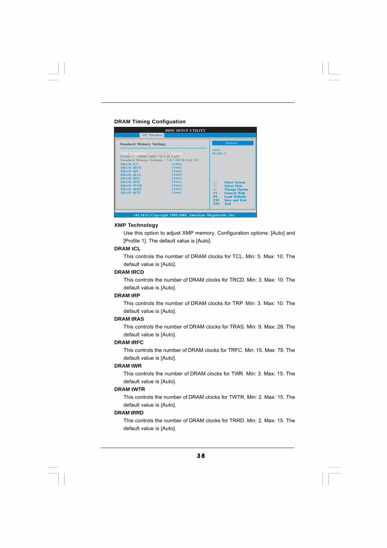
XMP TechnologyUse this option to adjust XMP memory. Configuration options: [Auto] and[Profile 1]. The default value is [Auto].
DRAM tCLThis controls the number of DRAM clocks for TCL. Min: 5. Max: 10. Thedefault value is [Auto].
DRAM tRCDThis controls the number of DRAM clocks for TRCD. Min: 3. Max: 10. Thedefault value is [Auto].
DRAM tRPThis controls the number of DRAM clocks for TRP. Min: 3. Max: 10. Thedefault value is [Auto].
DRAM tRASThis controls the number of DRAM clocks for TRAS. Min: 9. Max: 28. Thedefault value is [Auto].
DRAM tRFCThis controls the number of DRAM clocks for TRFC. Min: 15. Max: 78. Thedefault value is [Auto].
DRAM tWRThis controls the number of DRAM clocks for TWR. Min: 3. Max: 15. Thedefault value is [Auto].
DRAM tWTRThis controls the number of DRAM clocks for TWTR. Min: 2. Max: 15. Thedefault value is [Auto].
DRAM tRRDThis controls the number of DRAM clocks for TRRD. Min: 2. Max: 15. Thedefault value is [Auto].
DRAM Timing Configuation

3 93 93 93 93 9
DRAM tRTPThis controls the number of DRAM clocks for TRTP. Min: 2. Max: 13. Thedefault value is [Auto].
4 04 04 04 04 0
BIOS SETUP UTILITY
DRAM RCOMP Settings
Select ScreenSelect Item
+- Change OptionF1 General HelpF9 Load DefaultsF10 Save and ExitESC Exit
v02.54 (C) Copyright 1985-2005, American Megatrends, Inc.
OC Tweaker
Select ScreenSelect Item
+- Change OptionF1 General HelpF9 Load DefaultsF10 Save and ExitESC Exit
DRAM CH0 RCOMP ODTValue
Min = 1Max - 63
DRAM CH0 RCOMP ODT [Auto]DRAM CH0 G0 (Data)DRAM CH0 G1 (Command)DRAM CH0 G2 (Control1)DRAM CH0 G3 (Control2)DRAM CH0 G4 (Clocks1)DRAM CH0 G5 (Clocks2)
[Auto][Auto][Auto][Auto][Auto][Auto]
DRAM CH0 RCOMP Settings : 54-0-11-6-6-6-6
DRAM CH1 RCOMP ODTDRAM CH1 G0 (Data)DRAM CH1 G1 (Command)DRAM CH1 G2 (Control1)DRAM CH1 G3 (Control2)DRAM CH1 G4 (Clocks1)DRAM CH1 G5 (Clocks2)
[Auto][Auto][Auto][Auto][Auto][Auto][Auto]
DRAM CH1 RCOMP Settings : 54-0-8-8-0-8-0
DRAM RCOMP and tRD Configuration
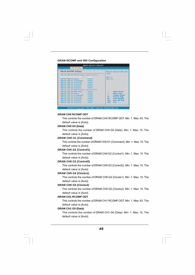
DRAM CH0 RCOMP ODTThis controls the number of DRAM CH0 RCOMP ODT. Min: 1. Max: 63. Thedefault value is [Auto].
DRAM CH0 G0 (Data)This controls the number of DRAM CH0 G0 (Data). Min: 1. Max: 15. Thedefault value is [Auto].
DRAM CH0 G1 (Command)This controls the number of DRAM CH0 G1 (Command). Min: 1. Max: 15. Thedefault value is [Auto].
DRAM CH0 G2 (Control1)This controls the number of DRAM CH0 G2 (Control1). Min: 1. Max: 15. Thedefault value is [Auto].
DRAM CH0 G3 (Control2)This controls the number of DRAM CH0 G3 (Control2). Min: 1. Max: 15. Thedefault value is [Auto].
DRAM CH0 G4 (Clocks1)This controls the number of DRAM CH0 G4 (Clocks1). Min: 1. Max: 15. Thedefault value is [Auto].
DRAM CH0 G5 (Clocks2)This controls the number of DRAM CH0 G5 (Clocks2). Min: 1. Max: 15. Thedefault value is [Auto].
DRAM CH1 RCOMP ODTThis controls the number of DRAM CH1 RCOMP ODT. Min: 1. Max: 63. Thedefault value is [Auto].
DRAM CH1 G0 (Data)This controls the number of DRAM CH1 G0 (Data). Min: 1. Max: 15. Thedefault value is [Auto].

4 14 14 14 14 1
DRAM CH1 G1 (Command)This controls the number of DRAM CH1 G1 (Command). Min: 1. Max: 15. Thedefault value is [Auto].
DRAM CH1 G2 (Control1)This controls the number of DRAM CH1 G2 (Control1). Min: 1. Max: 15. Thedefault value is [Auto].
DRAM CH1 G3 (Control2)This controls the number of DRAM CH1 G3 (Control2). Min: 1. Max: 15. Thedefault value is [Auto].
DRAM CH1 G4 (Clocks1)This controls the number of DRAM CH1 G4 (Clocks1). Min: 1. Max: 15. Thedefault value is [Auto].
DRAM CH1 G5 (Clocks2)This controls the number of DRAM CH1 G5 (Clocks2). Min: 1. Max: 15. Thedefault value is [Auto].
DRAM tRD SettingsDRAM CH0 tRD
This controls the number of DRAM CH0 tRD. Min: 0. Max: 30. The defaultvalue is [Auto].
DRAM CH1 tRDThis controls the number of DRAM CH1 tRD. Min: 0. Max: 30. The defaultvalue is [Auto].

4 24 24 24 24 2
BIOS SETUP UTILITY
DRAM DLL SKEW Settings
Select ScreenSelect Item
+- Change OptionF1 General HelpF9 Load DefaultsF10 Save and ExitESC Exit
v02.54 (C) Copyright 1985-2005, American Megatrends, Inc.
OC Tweaker
Select ScreenSelect Item
+- Change OptionF1 General HelpF9 Load DefaultsF10 Save and ExitESC Exit
DRAM CH0 CLKSET0 SKEW [Auto]
DRAM CH0 CLKSET0 SKEW Info:8-2-0-0-0-734
DRAM CH0 CLKSET1 SKEW [Auto]
DRAM CH0 CLKSET1 SKEW Info:9-5-0-0-0-856
DRAM CH0 CMD SKEW [Auto]
DRAM CH0 CMD SKEW Info :6-1-0-0-0-545
DRAM CH0 CTRL0 SKEW [Auto]
DRAM CH0 CTRL0 SKEW Info :8-4-0-0-0-756
DRAM CH0 CTRL1 SKEW [Auto]
DRAM CH0 CTRL1 SKEW Info :8-4-0-0-0-756
DRAM CH0 CTRL2 SKEW [Auto]
DRAM CH0 CTRL2 SKEW Info :10-0-0-0-0-890
DRAM CH0 CTRL3 SKEW [Auto]
DRAM CH0 CTRL3 SKEW Info :10-0-0-0-0-890
DRAM CH1 CLKSET0 SKEW Info :0-0-0-0-0-0
DRAM DLL SKEW Settings
DRAM CH0 CLKSET0 SKEWThis controls the number of DRAM CH0 CLKSET0 SKEW. Configurationoptions: [Auto], [8] to [827]. The default value is [Auto].
DRAM CH0 CLKSET1 SKEWThis controls the number of DRAM CH0 CLKSET1 SKEW. Configurationoptions: [Auto], [8] to [827]. The default value is [Auto].
DRAM CH0 CMD SKEWThis controls the number of DRAM CH0 CMD SKEW. Configuration options:[Auto], [8] to [827]. The default value is [Auto].
DRAM CH0 CTRL0 SKEWThis controls the number of DRAM CH0 CTRL0 SKEW. Configuration options:[Auto], [8] to [827]. The default value is [Auto].
DRAM CH0 CTRL1 SKEWThis controls the number of DRAM CH0 CTRL1 SKEW. Configuration options:[Auto], [8] to [827]. The default value is [Auto].
DRAM CH0 CTRL2 SKEWThis controls the number of DRAM CH0 CTRL2 SKEW. Configuration options:[Auto], [8] to [827]. The default value is [Auto].
DRAM CH0 CTRL3 SKEWThis controls the number of DRAM CH0 CTRL3 SKEW. Configuration options:[Auto], [8] to [827]. The default value is [Auto].
DRAM CH1 CLKSET0 SKEWThis controls the number of DRAM CH1 CLKSET0 SKEW. Configurationoptions: [Auto], [8] to [827]. The default value is [Auto].
DRAM CH1 CLKSET1 SKEWThis controls the number of DRAM CH1 CLKSET1 SKEW. Configurationoptions: [Auto], [8] to [827]. The default value is [Auto].
4 34 34 34 34 3
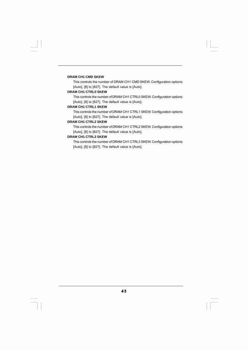
DRAM CH1 CMD SKEWThis controls the number of DRAM CH1 CMD SKEW. Configuration options:[Auto], [8] to [827]. The default value is [Auto].
DRAM CH1 CTRL0 SKEWThis controls the number of DRAM CH1 CTRL0 SKEW. Configuration options:[Auto], [8] to [827]. The default value is [Auto].
DRAM CH1 CTRL1 SKEWThis controls the number of DRAM CH1 CTRL1 SKEW. Configuration options:[Auto], [8] to [827]. The default value is [Auto].
DRAM CH1 CTRL2 SKEWThis controls the number of DRAM CH1 CTRL2 SKEW. Configuration options:[Auto], [8] to [827]. The default value is [Auto].
DRAM CH1 CTRL3 SKEWThis controls the number of DRAM CH1 CTRL3 SKEW. Configuration options:[Auto], [8] to [827]. The default value is [Auto].
4 44 44 44 44 4
BIOS SETUP UTILITY
Voltage Settings
Select ScreenSelect Item
+- Change OptionF1 General HelpF9 Load DefaultsF10 Save and ExitESC Exit
v02.54 (C) Copyright 1985-2005, American Megatrends, Inc.
OC Tweaker
Select ScreenSelect Item
+- Change OptionF1 General HelpF9 Load DefaultsF10 Save and ExitESC Exit
CPU Voltage [Auto]
DRAM VoltageGTLRef VoltageNB VoltageNB GTL Ref. VoltageSB Core VoltageSB 1.1V VoltageVTT VoltagePLL Voltage
[Auto][Auto][Auto][Auto][Auto][Auto][Auto][Auto]
AutoManualOverdrive Offset
Options
Voltage Settings
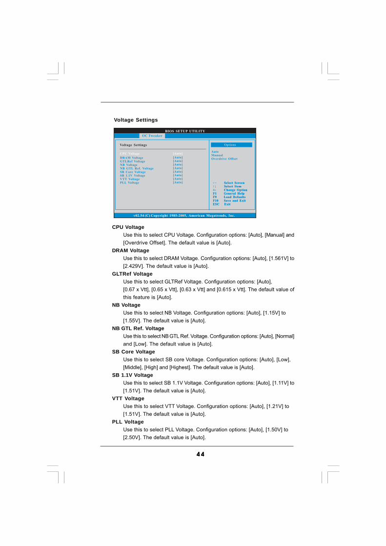
CPU VoltageUse this to select CPU Voltage. Configuration options: [Auto], [Manual] and[Overdrive Offset]. The default value is [Auto].
DRAM VoltageUse this to select DRAM Voltage. Configuration options: [Auto], [1.561V] to[2.429V]. The default value is [Auto].
GLTRef VoltageUse this to select GLTRef Voltage. Configuration options: [Auto],[0.67 x Vtt], [0.65 x Vtt], [0.63 x Vtt] and [0.615 x Vtt]. The default value ofthis feature is [Auto].
NB VoltageUse this to select NB Voltage. Configuration options: [Auto], [1.15V] to[1.55V]. The default value is [Auto].
NB GTL Ref. VoltageUse this to select NB GTL Ref. Voltage. Configuration options: [Auto], [Normal]and [Low]. The default value is [Auto].
SB Core VoltageUse this to select SB core Voltage. Configuration options: [Auto], [Low],[Middle], [High] and [Highest]. The default value is [Auto].
SB 1.1V VoltageUse this to select SB 1.1V Voltage. Configuration options: [Auto], [1.11V] to[1.51V]. The default value is [Auto].
VTT VoltageUse this to select VTT Voltage. Configuration options: [Auto], [1.21V] to[1.51V]. The default value is [Auto].
PLL VoltageUse this to select PLL Voltage. Configuration options: [Auto], [1.50V] to[2.50V]. The default value is [Auto].

4 54 54 54 54 5
ASRock VDrop ControlUse this to enable or disable ASRock VDrop control. Configuration options:[With VDrop] and [Without VDrop]. The default value is [With VDrop].
Would you like to save current setting user defaults?In this option, you are allowed to load and save three user defaultsaccording to your own requirements.

4 64 64 64 64 6
BIOS SETUP UTILITY
Main OC Tweaker H/W Monitor Boot Security Exit
Select ScreenSelect Item
Enter Go to Sub ScreenF1 General HelpF9 Load DefaultsF10 Save and ExitESC Exit
v02.54 (C) Copyright 1985-2005, American Megatrends, Inc.
Advanced
Advanced Settings
WARNING : Setting wrong values in below sectionsmay cause system to malfunction.
CPU Configuration
ACPI ConfigurationChipset Configuration
Storage ConfigurationPCIPnP ConfigurationFloppy ConfigurationSuperIO ConfigurationUSB Configuration
Options for CPU
BIOS Update Utility
ASRock Instant Flash
3.43 .43 .43 .43 .4 Advanced ScreenAdvanced ScreenAdvanced ScreenAdvanced ScreenAdvanced ScreenIn this section, you may set the configurations for the following items: CPUConfiguration, Chipset Configuration, ACPI Configuration, Storage Configuration, PCIPnPConfiguration, Floppy Configuration, SuperIO Configuration, and USB Configuration.
Setting wrong values in this section may causethe system to malfunction.
ASRock Instant FlashASRock Instant Flash is a BIOS flash utility embedded in Flash ROM. Thisconvenient BIOS update tool allows you to update system BIOS withoutentering operating systems first like MS-DOS or Windows®. Just launchthis tool and save the new BIOS file to your USB flash drive, floppy disk orhard drive, then you can update your BIOS only in a few clicks withoutpreparing an additional floppy diskette or other complicated flash utility.Please be noted that the USB flash drive or hard drive must use FAT32/16/12 file system. If you execute ASRock Instant Flash utility, the utility willshow the BIOS files and their respective information. Select the properBIOS file to update your BIOS, and reboot your system after BIOS updateprocess completes.
4 74 74 74 74 7
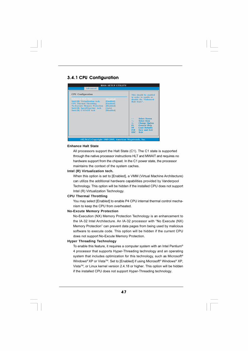
Enhance Halt StateAll processors support the Halt State (C1). The C1 state is supportedthrough the native processor instructions HLT and MWAIT and requires nohardware support from the chipset. In the C1 power state, the processormaintains the context of the system caches.
Intel (R) Virtualization tech.When this option is set to [Enabled], a VMM (Virtual Machine Architecture)can utilize the additional hardware capabilities provided by VanderpoolTechnology. This option will be hidden if the installed CPU does not supportIntel (R) Virtualization Technology.
CPU Thermal ThrottlingYou may select [Enabled] to enable P4 CPU internal thermal control mecha-nism to keep the CPU from overheated.
No-Excute Memory ProtectionNo-Execution (NX) Memory Protection Technology is an enhancement tothe IA-32 Intel Architecture. An IA-32 processor with “No Execute (NX)Memory Protection” can prevent data pages from being used by malicioussoftware to execute code. This option will be hidden if the current CPUdoes not support No-Excute Memory Protection.
Hyper Threading TechnologyTo enable this feature, it requires a computer system with an Intel Pentium®
4 processor that supports Hyper-Threading technology and an operatingsystem that includes optimization for this technology, such as Microsoft®
Windows® XP or VistaTM. Set to [Enabled] if using Microsoft® Windows® XP,VistaTM, or Linux kernel version 2.4.18 or higher. This option will be hiddenif the installed CPU does not support Hyper-Threading technology.
3.4.13.4.13.4.13.4.13.4.1 CPU ConfigurationCPU ConfigurationCPU ConfigurationCPU ConfigurationCPU Configuration
BIOS SETUP UTILITY
CPU Configuration This should be enabledin order to enable ordisable the “EnhancedHalt State”.
Select ScreenSelect Item
+- Change OptionF1 General HelpF9 Load DefaultsF10 Save and ExitESC Exit
v02.54 (C) Copyright 1985-2005, American Megatrends, Inc.
Advanced
Enhanced Halt State [Disabled]
Select ScreenSelect Item
+- Change OptionF1 General HelpF9 Load DefaultsF10 Save and ExitESC Exit
Intel (R) Virtualization tech.CPU Thermal ThrottlingNo-Execute Memory ProtectionIntel (R) SpeedStep (tm) tech.Intel (R) C-STATE tech
[Enabled][Enabled][Disabled][Auto][Disabled]
4 84 84 84 84 8
Please note that enabling this function may reduce CPU voltage and lead to systemstability or compatibility issue with some power supplies. Please set this item to[Disable] if above issue occurs.
Intel (R) C-STATE tech.Intel (R) C-STATE tech. is achieved by making the power and thermal controlunit part of the core logic and not part of the chipset as before. Migration of thepower and thermal management flow into the processor allows us to use ahardware coordination mechanism in which each core can request any C-stateit wishes, thus allowing for individual core savings to be maximized. The CPUC-state is determined and entered based on the lowest common denominatorof both cores’ requests, portraying a single CPU entity to the chipset powermanagement hardware and flows. Thus, software can manage each coreindependently, while the actual power management adheres to the plat-form and CPU shared resource restrictions. Configuration options are:[C2], [C3], [C4] and [Disabled]. The default value is [Disabled].
Intel (R) SpeedStep(tm) tech.Intel (R) SpeedStep(tm) tech. is Intel’s new power saving technology.Processor can switch between multiple frequency and voltage points toenable power savings. The default value is [Auto]. Configuration options:[Auto], [Enabled] and [Disabled]. If you install Windows® XP and select[Auto], you need to set the “Power Schemes” as “Portable/Laptop” to en-able this function. If you install Windows® VistaTM and want to enable thisfunction, please set this item to [Enabled]. This item will be hidden if thecurrent CPU does not support Intel (R) SpeedStep(tm) tech..

4 94 94 94 94 9
3.4.23.4.23.4.23.4.23.4.2 Chipset ConfigurationChipset ConfigurationChipset ConfigurationChipset ConfigurationChipset Configuration
BIOS SETUP UTILITY
Chipset Settings
Select ScreenSelect Item
+- Change OptionF1 General HelpF9 Load DefaultsF10 Save and ExitESC Exit
v02.54 (C) Copyright 1985-2005, American Megatrends, Inc.
Advanced
Select ScreenSelect Item
+- Change OptionF1 General HelpF9 Load DefaultsF10 Save and ExitESC Exit
Intelligent Energy Saver [Disabled]
Primary Graphics AdapterOnboard HD Audio
Front PanelOnBoard LanCIR10 Field 1
[PCI][Auto][Enabled][Enabled][Enabled]
DisabledEnabled
Options
Intelligent Energy SaverIntelligent Energy Saver is a revolutionary technology that deliversunparalleled power savings. The default value is [Disabled]. Configurationoptions: [Auto], [Enabled] and [Disabled]. If you want to enable this function,please set this item to [Enabled]. Besides the BIOS option, you can alsochoose our Intelligent Energy Saver utility to enable this function.
Primary Graphics AdapterThis allows you to select [PCI] or [PCI Express] as the boot graphic adapterpriority. The default value is [PCI].
Onboard HD AudioSelect [Auto], [Enabled] or [Disabled] for the onboard HD Audio feature. Ifyou select [Auto], the onboard HD Audio will be disabled when PCI SoundCard is plugged.
Front PanelSelect [Auto], [Enabled] or [Disabled] for the onboard HD Audio Front Panel.
OnBoard LanThis allows you to enable or disable the “OnBoard Lan” feature.
CIR10 Field 1Use this to enable or disable CIR10 Field 1. The default value of this feature is [Enabled].

5 05 05 05 05 0
BIOS SETUP UTILITY
ACPI Configuration Select auto-detect ordisable the STRfeature.
Select ScreenSelect Item
+- Change OptionF1 General HelpF9 Load DefaultsF10 Save and ExitESC Exit
v02.54 (C) Copyright 1985-2005, American Megatrends, Inc.
Advanced
Suspend To RAM
Restore on AC/Power LossRing-In Power OnPCI Devices Power OnPS / 2 Keyboard Power OnRTC Alarm Power On
ACPI HPET Table
EUP Support
[Disabled]
[Power Off][Disabled][Disabled][Disabled][Disabled]
[Disabled]
[Auto]
3.4.33.4.33.4.33.4.33.4.3 ACPI ConfigurationACPI ConfigurationACPI ConfigurationACPI ConfigurationACPI Configuration
Suspend to RAMUse this item to select whether to auto-detect or disable the Suspend-to-RAM feature. Select [Auto] will enable this feature if the OS supports it. Ifyou set this item to [Disabled], the function “Repost Video on STR Resume”will be hidden.
Repost Video on STR ResumeThis feature allows you to repost video on STR resume. (STR refers tosuspend to RAM.)
Check Ready BitUse this item to enable or disable the feature Check Ready Bit.
Restore on AC/Power LossThis allows you to set the power state after an unexpected AC/powerloss. If [Power Off] is selected, the AC/power remains off when the powerrecovers. If [Power On] is selected, the AC/power resumes and thesystem starts to boot up when the power recovers.
Ring-In Power OnUse this item to enable or disable Ring-In signals to turn on the system fromthe power-soft-off mode.
PCI Devices Power OnUse this item to enable or disable PCI devices to turn on the system from thepower-soft-off mode.
PS/2 Keyboard Power OnUse this item to enable or disable PS/2 keyboard to turn on the system fromthe power-soft-off mode.
RTC Alarm Power OnUse this item to enable or disable RTC (Real Time Clock) to power on thesystem.

5 15 15 15 15 1
BIOS SETUP UTILITY
Storage Configuration
v02.54 (C) Copyright 1985-2003, American Megatrends, Inc.
Advanced
SATAII Configuration
SATAII 1SATAII 2SATAII 3SATAII 4SATAII 5SATAII 6IDE1 MasterIDE1 Slave
[Enhanced]
[Hard Disk][Not Detected][Not Detected][Not Detected][Not Detected][Not Detected][Not Detected][Not Detected]
Select ScreenSelect Item
+- Change OptionF1 General HelpF9 Load DefaultsF10 Save and ExitESC Exit
Select ScreenSelect Item
+- Change OptionF1 General HelpF9 Load DefaultsF10 Save and ExitESC Exit
Configure SATAII as [IDE]
DisabledCompatibleEnhanced
AHCI CD/DVD Boot Time out [35]
Options
OnBoard IDE Controller [Enabled]
3.4.43.4.43.4.43.4.43.4.4 Storage ConfigurationStorage ConfigurationStorage ConfigurationStorage ConfigurationStorage Configuration
SATAII ConfigurationPlease select [Compatible] when you install legacy OS. If native OS(Windows® 2000 / XP / VistaTM) is installed, please select [Enhanced].Then in the option “Configure SATAII as”, you are allowed to set the selec-tion to [IDE] or [AHCI]. The default value is [IDE].If you select [AHCI] mode, the options “Hot Plug” and “SATA Link PowerManagement” will appear. Configuration options: [Enabled] and [Disabled].The default value is [Enabled].
AHCI (Advanced Host Controller Interface) supports NCQ and othernew features that will improve SATA disk performance but IDEmode does not have these advantages.
OnBoard IDE ControllerUse this item to enable or disable onboard IDE controller. The default valueis [Enabled].
IDE Device ConfigurationYou may set the IDE configuration for the device that you specify. We willuse the “Primary IDE Master” as the example in the following instruction.
EUP SupportUse this item to enable or disable EuP. The default value is [Auto].
ACPI HPET TableUse this item to enable or disable ACPI HPET Table. The default value is[Disabled]. Please set this option to [Enabled] if you plan to use thismotherboard to submit Windows® VistaTM certification.
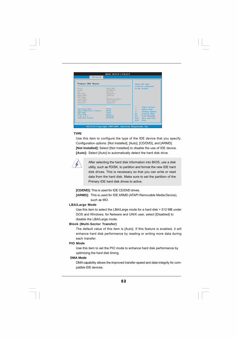
5 25 25 25 25 2
[CD/DVD]: This is used for IDE CD/DVD drives.[ARMD]: This is used for IDE ARMD (ATAPI Removable Media Device),
such as MO.LBA/Large Mode
Use this item to select the LBA/Large mode for a hard disk > 512 MB underDOS and Windows; for Netware and UNIX user, select [Disabled] todisable the LBA/Large mode.
Block (Multi-Sector Transfer)The default value of this item is [Auto]. If this feature is enabled, it willenhance hard disk performance by reading or writing more data duringeach transfer.
PIO ModeUse this item to set the PIO mode to enhance hard disk performance byoptimizing the hard disk timing.
DMA ModeDMA capability allows the improved transfer-speed and data-integrity for com-patible IDE devices.
BIOS SETUP UTILITY
Primary IDE Master Select the typeof device connectedto the system.
Select ScreenSelect Item
+- Change OptionF1 General HelpF9 Load DefaultsF10 Save and ExitESC Exit
v02.54 (C) Copyright 1985-2005, American Megatrends, Inc.
Advanced
Type
LBA/Large ModeBlock (Multi-Sector Transfer)PIO ModeDMA ModeS . M . A . R . T .32Bit Data Transfer
[Auto]
[Auto][Auto][Auto][Auto][Disabled][Enabled]
DeviceVendorSizeLBA ModeBlock ModePIO ModeAsync DMAUltra DMAS.M.A.R.T.
:Hard Disk:ST340014A:40.0 GB:Supported:16Sectors:4:MultiWord DMA-2:Ultra DMA-5:Supported
TYPEUse this item to configure the type of the IDE device that you specify.Configuration options: [Not Installed], [Auto], [CD/DVD], and [ARMD].[Not Installed]: Select [Not Installed] to disable the use of IDE device.[Auto]: Select [Auto] to automatically detect the hard disk drive.
After selecting the hard disk information into BIOS, use a diskutility, such as FDISK, to partition and format the new IDE harddisk drives. This is necessary so that you can write or readdata from the hard disk. Make sure to set the partition of thePrimary IDE hard disk drives to active.
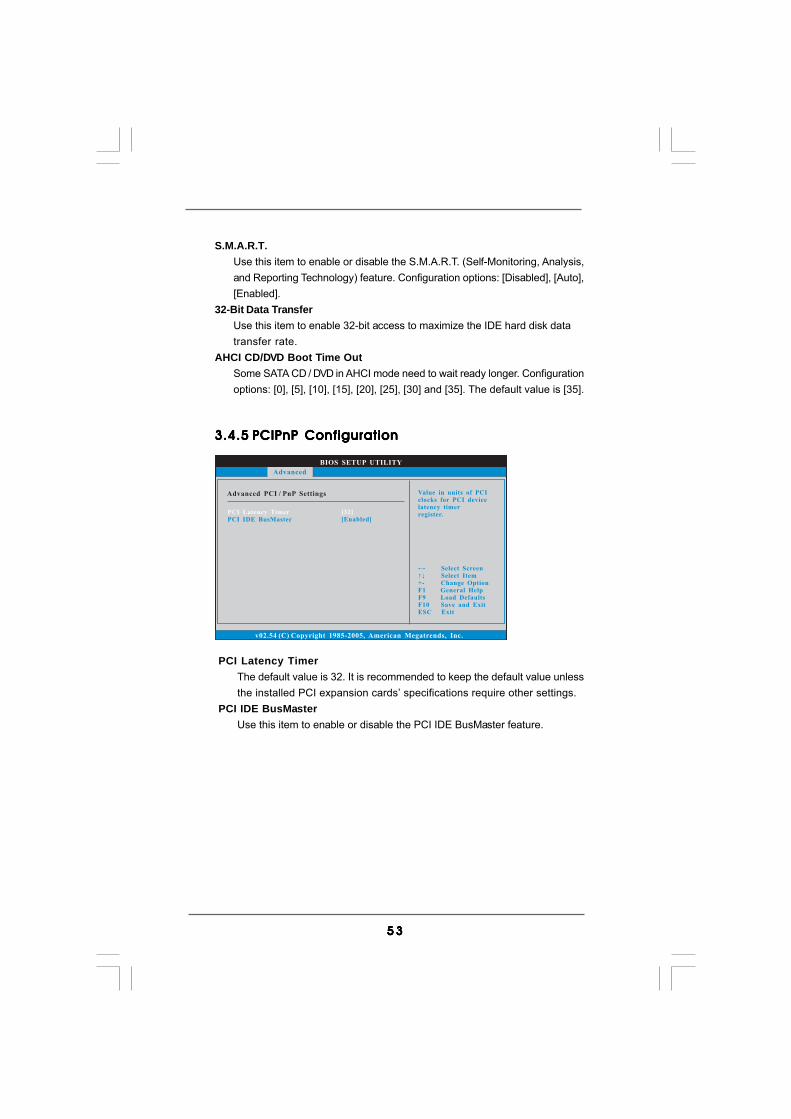
5 35 35 35 35 3
S.M.A.R.T.Use this item to enable or disable the S.M.A.R.T. (Self-Monitoring, Analysis,and Reporting Technology) feature. Configuration options: [Disabled], [Auto],[Enabled].
32-Bit Data TransferUse this item to enable 32-bit access to maximize the IDE hard disk datatransfer rate.
AHCI CD/DVD Boot Time OutSome SATA CD / DVD in AHCI mode need to wait ready longer. Configurationoptions: [0], [5], [10], [15], [20], [25], [30] and [35]. The default value is [35].
BIOS SETUP UTILITY
Advanced PCI / PnP Settings Value in units of PCIclocks for PCI devicelatency timerregister.
Select ScreenSelect Item
+- Change OptionF1 General HelpF9 Load DefaultsF10 Save and ExitESC Exit
v02.54 (C) Copyright 1985-2005, American Megatrends, Inc.
PCI Latency TimerPCI IDE BusMaster
[32][Enabled]
Advanced
3.4.53.4.53.4.53.4.53.4.5 PCIPnP ConfigurationPCIPnP ConfigurationPCIPnP ConfigurationPCIPnP ConfigurationPCIPnP Configuration
PCI Latency TimerThe default value is 32. It is recommended to keep the default value unlessthe installed PCI expansion cards’ specifications require other settings.
PCI IDE BusMasterUse this item to enable or disable the PCI IDE BusMaster feature.
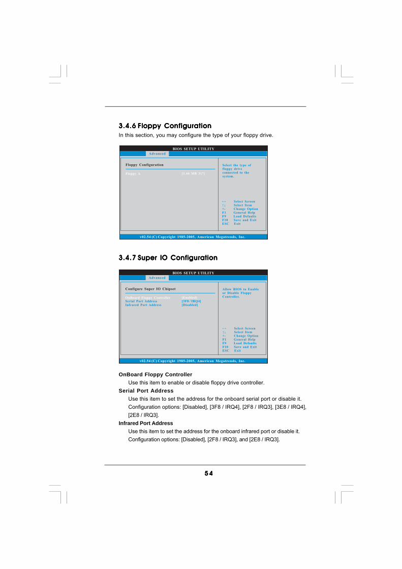
5 45 45 45 45 4
3.4.63.4.63.4.63.4.63.4.6 Floppy ConfigurationFloppy ConfigurationFloppy ConfigurationFloppy ConfigurationFloppy ConfigurationIn this section, you may configure the type of your floppy drive.
3.4.73.4.73.4.73.4.73.4.7 Super IO ConfigurationSuper IO ConfigurationSuper IO ConfigurationSuper IO ConfigurationSuper IO Configuration
OnBoard Floppy ControllerUse this item to enable or disable floppy drive controller.
Serial Port AddressUse this item to set the address for the onboard serial port or disable it.Configuration options: [Disabled], [3F8 / IRQ4], [2F8 / IRQ3], [3E8 / IRQ4],[2E8 / IRQ3].
Infrared Port AddressUse this item to set the address for the onboard infrared port or disable it.Configuration options: [Disabled], [2F8 / IRQ3], and [2E8 / IRQ3].
BIOS SETUP UTILITY
Floppy Configuration Select the type offloppy driveconnected to thesystem.
Select ScreenSelect Item
+- Change OptionF1 General HelpF9 Load DefaultsF10 Save and ExitESC Exit
v02.54 (C) Copyright 1985-2005, American Megatrends, Inc.
Advanced
Floppy A [1.44 MB 3 "]12
BIOS SETUP UTILITY
Configure Super IO Chipset Allow BIOS to Enableor Disable FloppyController.
Select ScreenSelect Item
+- Change OptionF1 General HelpF9 Load DefaultsF10 Save and ExitESC Exit
v02.54 (C) Copyright 1985-2005, American Megatrends, Inc.
Advanced
OnBoard Floppy ControllerSerial Port AddressInfrared Port Address
[Enabled][3F8 / IRQ4][Disabled]
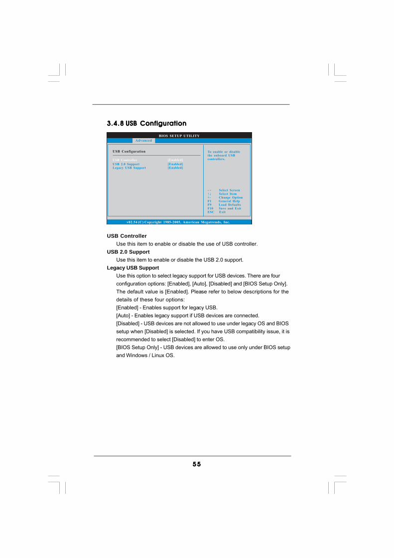
5 55 55 55 55 5
3.4.83.4.83.4.83.4.83.4.8 USB ConfigurationUSB ConfigurationUSB ConfigurationUSB ConfigurationUSB Configuration
USB ControllerUse this item to enable or disable the use of USB controller.
USB 2.0 SupportUse this item to enable or disable the USB 2.0 support.
Legacy USB SupportUse this option to select legacy support for USB devices. There are fourconfiguration options: [Enabled], [Auto], [Disabled] and [BIOS Setup Only].The default value is [Enabled]. Please refer to below descriptions for thedetails of these four options:[Enabled] - Enables support for legacy USB.[Auto] - Enables legacy support if USB devices are connected.[Disabled] - USB devices are not allowed to use under legacy OS and BIOSsetup when [Disabled] is selected. If you have USB compatibility issue, it isrecommended to select [Disabled] to enter OS.[BIOS Setup Only] - USB devices are allowed to use only under BIOS setupand Windows / Linux OS.
BIOS SETUP UTILITY
USB Configuration To enable or disablethe onboard USBcontrollers.
Select ScreenSelect Item
+- Change OptionF1 General HelpF9 Load DefaultsF10 Save and ExitESC Exit
v02.54 (C) Copyright 1985-2005, American Megatrends, Inc.
Advanced
USB Controller
USB 2.0 SupportLegacy USB Support
[Enabled]
[Enabled][Enabled]

5 65 65 65 65 6
BIOS SETUP UTILITY
Hardware Health Event Monitoring
Select ScreenSelect Item
F1 General HelpF9 Load DefaultsF10 Save and ExitESC Exit
v02.54 (C) Copyright 1985-2003, American Megatrends, Inc.
CPU TemperatureM / B Temperature
CPU Fan SpeedChassis Fan SpeedPower Fan Speed
Vcore+ 3.30V+ 5.00V+ 12.00V
: 37 C / 98 F
: 3400 RPM: N / A
: 1.629V: 3.306V: 5.067V: 11.890V
: 31 C / 87 F
: N / A
Main OC Tweaker Advanced Boot Security ExitH/W Monitor
Enable/DisableCPU Quiet FanFunction.
CPU Quiet Fan [Disabled]
3.53 .53 .53 .53 .5 Hardware Health Event Monitoring ScreenHardware Health Event Monitoring ScreenHardware Health Event Monitoring ScreenHardware Health Event Monitoring ScreenHardware Health Event Monitoring ScreenIn this section, it allows you to monitor the status of the hardware on your system,including the parameters of the CPU temperature, motherboard temperature, CPU fanspeed, chassis fan speed, and the critical voltage.
CPU Quiet FanThis item allows you to identify the temperature of CPU fan. If you set thisoption as [Disabled], the CPU fan will operate in full speed. If you set thisoption as [Enabled], you will find the items “Target CPU Temperature” and“Target Fan Speed” appear to allow you adjusting them. The default value is[Disabled]. You are allowed to enable this function only when you install 4-pinCPU fan.
Target CPU Temperature
The target temperature will be between 45 C/113 F and 65 C/149 F. Thedefault value is [50 C/122 F].
Target Fan SpeedUse this option to set the target fan speed. You can freely adjust thetarget fan speed according to the target CPU temperature that youchoose. Configuration options: [Level 1], [Level 2], [Level 3], [Level 4],[Level 5], [Level 6] [Level 7], [Level 8] and [Level 9].
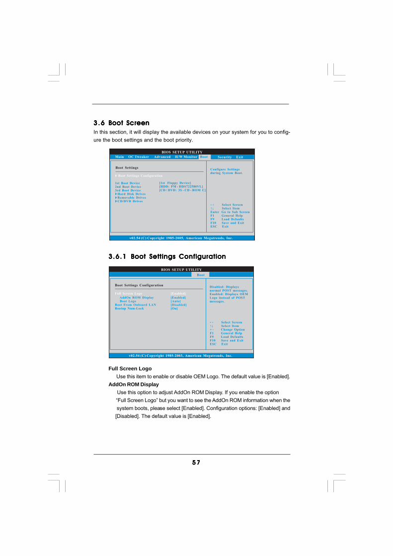
5 75 75 75 75 7
3.6.13.6.13.6.13.6.13.6.1 Boot Settings ConfigurationBoot Settings ConfigurationBoot Settings ConfigurationBoot Settings ConfigurationBoot Settings Configuration
Full Screen Logo Use this item to enable or disable OEM Logo. The default value is [Enabled].AddOn ROM Display Use this option to adjust AddOn ROM Display. If you enable the option “Full Screen Logo” but you want to see the AddOn ROM information when the system boots, please select [Enabled]. Configuration options: [Enabled] and [Disabled]. The default value is [Enabled].
BIOS SETUP UTILITY
Boot Settings ConfigurationDisabled: Displaysnormal POST messages.Enabled: Displays OEMLogo instead of POSTmessages.
Select ScreenSelect Item
+ - Change OptionF1 General HelpF9 Load DefaultsF10 Save and ExitESC Exit
v02.54 (C) Copyright 1985-2003, American Megatrends, Inc.
Boot
AddOn ROM DisplayBoot Logo
Boot From Onboard LANBootup Num-Lock
[Enabled][Auto][Disabled][On]
Full Screen Logo [Enabled]
3.63 .63 .63 .63 .6 Boot ScreenBoot ScreenBoot ScreenBoot ScreenBoot ScreenIn this section, it will display the available devices on your system for you to config-ure the boot settings and the boot priority.
BIOS SETUP UTILITY
Main OC Tweaker Advanced H/W Monitor Security Exit
Boot SettingsConfigure Settingsduring System Boot.
Select ScreenSelect Item
Enter Go to Sub ScreenF1 General HelpF9 Load DefaultsF10 Save and ExitESC Exit
v02.54 (C) Copyright 1985-2005, American Megatrends, Inc.
Boot
Boot Settings Configuration
1st Boot Device2nd Boot Device3rd Boot Device
Hard Disk DrivesRemovable DrivesCD/DVD Drives
[1st Floppy Device][HDD: PM - HDS722580VL][CD / DVD: 3S - CD - ROM C]

5 85 85 85 85 8
BIOS SETUP UTILITY
Main OC Tweaker Advanced H/W Monitor Boot Exit
Install or Change thepassword.
Select ScreenSelect Item
Enter ChangeF1 General Help
F10 Save and ExitESC Exit
F9 Load Defaults
v02.54 (C) Copyright 1985-2005, American Megatrends, Inc.
Security
Change Supervisor Password
Change User Password
Security Settings
Supervisor Password : Not InstalledUser Password : Not Installed
Boot LogoUse this option to select logo in POST screen. This option only appearswhen you enable the option “Full Screen Logo”. Configuration options:[Auto], [EuP], [Scenery] and [ASRock]. The default value is [Auto].
Boot From Onboard LANUse this item to enable or disable the Boot From Onboard LAN feature.
Boot Up Num-LockIf this item is set to [On], it will automatically activate the Numeric Lockfunction after boot-up.
3.73 .73 .73 .73 .7 Security ScreenSecurity ScreenSecurity ScreenSecurity ScreenSecurity ScreenIn this section, you may set or change the supervisor/user password for the system. Forthe user password, you may also clear it.

5 95 95 95 95 9
BIOS SETUP UTILITY
Main OC Tweaker Advanced H/W Monitor Boot Security
Exit system setupafter saving thechanges.
F10 key can be usedfor this operation.
Select ScreenSelect Item
Enter Go to Sub ScreenF1 General Help
F10 Save and ExitESC Exit
F9 Load Defaults
v02.54 (C) Copyright 1985-2005, American Megatrends, Inc.
Exit
Save Changes and Exit
Discard Changes and ExitDiscard Changes
Load BIOS DefaultsLoad Performance Setup Default (IDE/SATA)Load Performance Setup AHCI ModeLoad Power Saving Setup Default
Exit Options
3.83.83.83.83.8 Exit ScreenExit ScreenExit ScreenExit ScreenExit Screen
Save Changes and ExitWhen you select this option, it will pop-out the following message, “Saveconfiguration changes and exit setup?” Select [OK] to save the changesand exit the BIOS SETUP UTILITY.
Discard Changes and ExitWhen you select this option, it will pop-out the following message, “Dis-card changes and exit setup?” Select [OK] to exit the BIOS SETUP UTILITYwithout saving any changes.
Discard ChangesWhen you select this option, it will pop-out the following message, “Dis-card changes?” Select [OK] to discard all changes.
Load BIOS DefaultsLoad BIOS default values for all the setup questions. F9 key can be usedfor this operation.
Load Performance Setup Default (IDE/SATA)This performance setup default may not be compatible with all systemconfigurations. If system boot failure occurs after loading, please resumeoptimal default settings. F5 key can be used for this operation.
Load Performance Setup AHCI ModeThis performance setup AHCI mode may not be compatible with all systemconfigurations. If system boot failure occurs after loading, please resumeoptimal default settings. F3 key can be used for this operation.
Load Power Saving Setup DefaultLoad power saving setup default. F6 key can be used for this operation.
6 06 06 06 06 0
Chapter 4: SofChapter 4: SofChapter 4: SofChapter 4: SofChapter 4: Software Supportware Supportware Supportware Supportware Supporttttt4.14.14.14.14.1 Install Operating SystemInstall Operating SystemInstall Operating SystemInstall Operating SystemInstall Operating System
This motherboard supports various Microsoft® Windows® operating systems: 2000 /XP / XP 64-bit / VistaTM / VistaTM 64-bit / Win7. Because motherboard settings andhardware options vary, use the setup procedures in this chapter for general refer-ence only. Refer to your OS documentation for more information.
4.24 .24 .24 .24 .2 Support CD InformationSupport CD InformationSupport CD InformationSupport CD InformationSupport CD Information
The Support CD that came with the motherboard contains necessary drivers anduseful utilities that enhance the motherboard features.
4.2.14.2.14.2.14.2.14.2.1 Running The Support CDRunning The Support CDRunning The Support CDRunning The Support CDRunning The Support CD
To begin using the support CD, insert the CD into your CD-ROM drive. The CDautomatically displays the Main Menu if “AUTORUN” is enabled in your computer.If the Main Menu did not appear automatically, locate and double click on thefile “ASSETUP.EXE” from the BIN folder in the Support CD to display the menus.
4.2.24.2.24.2.24.2.24.2.2 Drivers MenuDrivers MenuDrivers MenuDrivers MenuDrivers Menu
The Drivers Menu shows the available devices drivers if the system detectsinstalled devices. Please install the necessary drivers to activate the devices.
4.2.34.2.34.2.34.2.34.2.3 Uti l i t ies MenuUti l i t ies MenuUti l i t ies MenuUti l i t ies MenuUti l i t ies Menu
The Utilities Menu shows the applications software that the motherboardsupports. Click on a specific item then follow the installation wizard to install it.
4.2.44.2.44.2.44.2.44.2.4 Contact Informat ionContact Informat ionContact Informat ionContact Informat ionContact Informat ion
If you need to contact ASRock or want to know more about ASRock, welcometo visit ASRock’s website at http://www.asrock.com; or you may contact yourdealer for further information.


