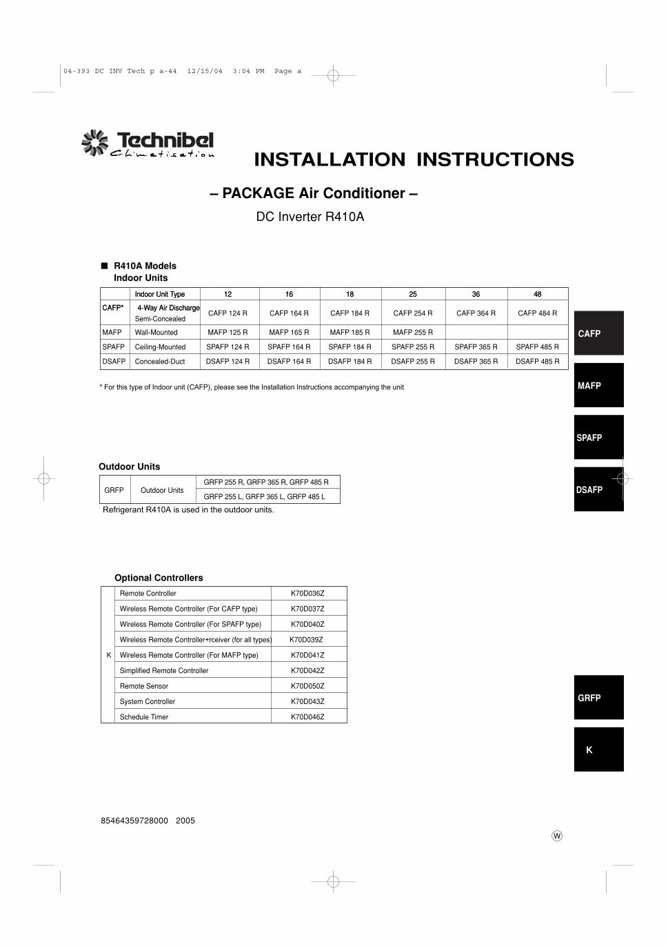
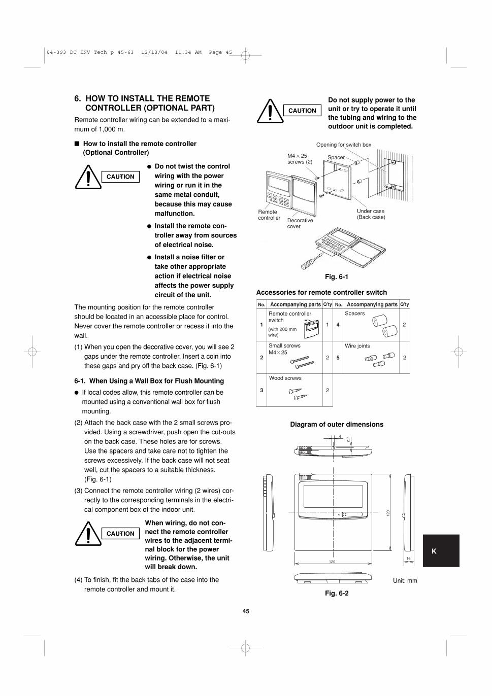
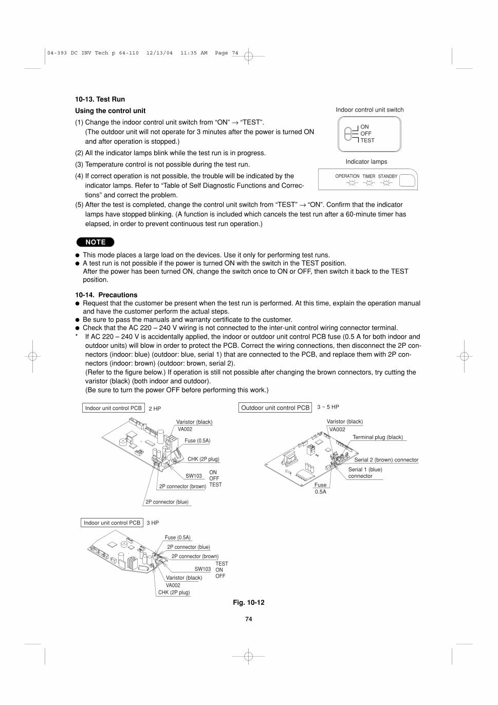
CAFP MAFP SPAFP DSAFP GRFP K 85464359728000 2005 W – PACKAGE Air Conditioner – INSTALLATION INSTRUCTIONS ■ R410A Models Indoor Units Outdoor Units Indoor Unit Type 12 16 18 25 36 48 CAFP* 4-Way Air Discharge Semi-Concealed CAFP 124 R CAFP 164 R CAFP 184 R CAFP 254 R CAFP 364 R CAFP 484 R MAFP Wall-Mounted MAFP 125 R MAFP 165 R MAFP 185 R MAFP 255 R SPAFP Ceiling-Mounted SPAFP 124 R SPAFP 164 R SPAFP 184 R SPAFP 255 R SPAFP 365 R SPAFP 485 R DSAFP Concealed-Duct DSAFP 124 R DSAFP 164 R DSAFP 184 R DSAFP 255 R DSAFP 365 R DSAFP 485 R Refrigerant R410A is used in the outdoor units. GRFP 255 R, GRFP 365 R, GRFP 485 R GRFP Outdoor Units GRFP 255 L, GRFP 365 L, GRFP 485 L Optional Controllers Remote Controller K70D036Z Wireless Remote Controller (For CAFP type) K70D037Z Wireless Remote Controller (For SPAFP type) K70D040Z Wireless Remote Controller+rceiver (for all types) K70D039Z K Wireless Remote Controller (For MAFP type) K70D041Z Simplified Remote Controller K70D042Z Remote Sensor K70D050Z System Controller K70D043Z Schedule Timer K70D046Z DC Inverter R410A 04-393 DC INV Tech p a-44 12/15/04 3:04 PM Page a Indoor Unit Type 12 16 18 25 36 48 CAFP* 4-Way Air Discharge * For this type of Indoor unit (CAFP), please see the Installation Instructions accompanying the unit
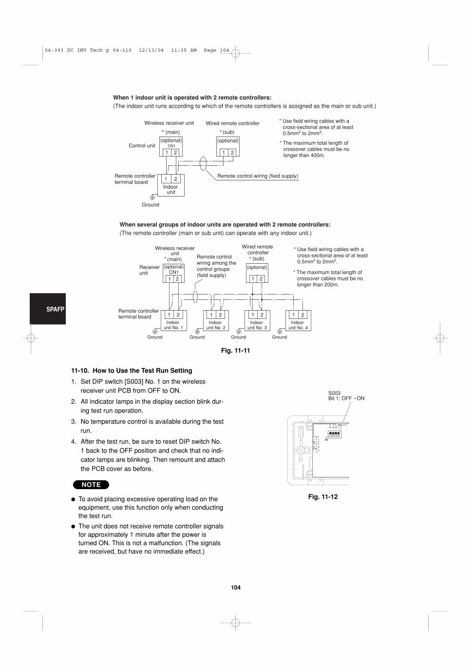
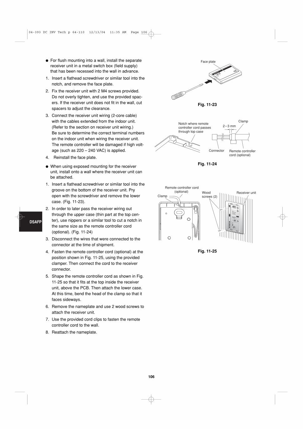
Transcript
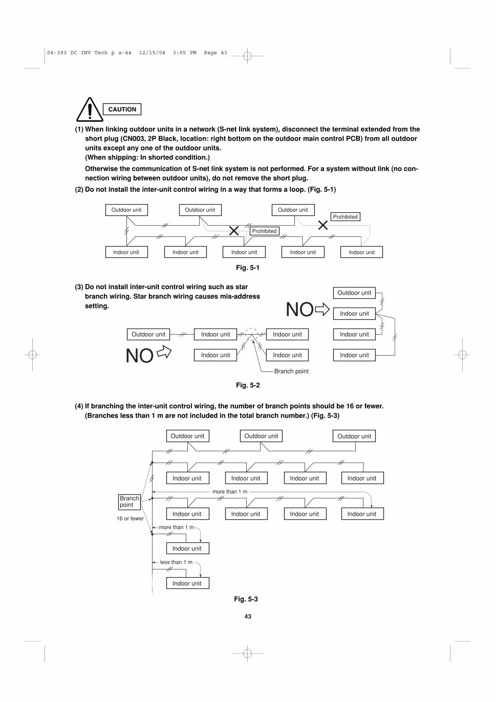
CAFP
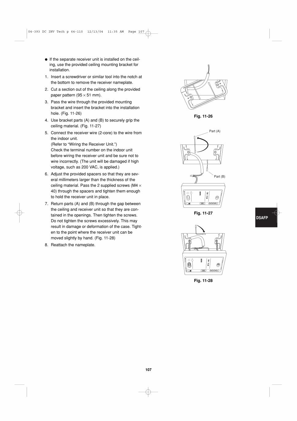
MAFP
SPAFP
DSAFP
GRFP
K
85464359728000 2005
W
– PACKAGE Air Conditioner –
INSTALLATION INSTRUCTIONS
� R410A ModelsIndoor Units
Outdoor Units
Indoor Unit Type 12 16 18 25 36 48
CAFP* 4-Way Air Discharge
Semi-ConcealedCAFP 124 R CAFP 164 R CAFP 184 R CAFP 254 R CAFP 364 R CAFP 484 R
MAFP Wall-Mounted MAFP 125 R MAFP 165 R MAFP 185 R MAFP 255 R
SPAFP Ceiling-Mounted SPAFP 124 R SPAFP 164 R SPAFP 184 R SPAFP 255 R SPAFP 365 R SPAFP 485 R
DSAFP Concealed-Duct DSAFP 124 R DSAFP 164 R DSAFP 184 R DSAFP 255 R DSAFP 365 R DSAFP 485 R
Wireless Remote Controller+rceiver (for all types) K70D039Z
K Wireless Remote Controller (For MAFP type) K70D041Z
Simplified Remote Controller K70D042Z
Remote Sensor K70D050Z
System Controller K70D043Z
Schedule Timer K70D046Z
DC Inverter R410A
04-393 DC INV Tech p a-44 12/15/04 3:04 PM Page a
Indoor Unit Type 12 16 18 25 36 48
CAFP* 4-Way Air Discharge
* For this type of Indoor unit (CAFP), please see the Installation Instructions accompanying the unit
2
IMPORTANT! Please Read Before Starting
This air conditioning system meets strict safety and operat-ing standards. As the installer or service person, it is animportant part of your job to install or service the system soit operates safely and efficiently.
For safe installation and trouble-free operation, youmust:� Carefully read this instruction booklet before beginning.� Follow each installation or repair step exactly as shown.� Observe all local, state, and national electrical codes.� Pay close attention to all warning and caution notices
given in this manual.This symbol refers to a hazardor unsafe practice which canresult in severe personal injuryor death.
This symbol refers to a hazardor unsafe practice which canresult in personal injury orproduct or property damage.
If Necessary, Get HelpThese instructions are all you need for most installationsites and maintenance conditions. If you require help fora special problem, contact our sales/service outlet oryour certified dealer for additional instructions.
In Case of Improper InstallationThe manufacturer shall in no way be responsible forimproper installation or maintenance service, includingfailure to follow the instructions in this document.
SPECIAL PRECAUTIONS
When Wiring
ELECTRICAL SHOCK CAN CAUSESEVERE PERSONAL INJURY OR DEATH.ONLY A QUALIFIED, EXPERIENCEDELECTRICIAN SHOULD ATTEMPT TOWIRE THIS SYSTEM.
• Do not supply power to the unit until all wiring and tub-ing are completed or reconnected and checked.
• Highly dangerous electrical voltages are used in thissystem. Carefully refer to the wiring diagram andthese instructions when wiring. Improper connectionsand inadequate grounding can cause accidentalinjury or death.
• Ground the unit following local electrical codes.
• Connect all wiring tightly. Loose wiring may cause over-heating at connection points and a possible fire hazard.
When Transporting
Be careful when picking up and moving the indoor and out-door units. Get a partner to help, and bend your knees whenlifting to reduce strain on your back. Sharp edges or thin alu-minum fins on the air conditioner can cut your fingers.
When Installing…
…In a Room
Properly insulate any tubing run inside a room to prevent“sweating” that can cause dripping and water damage towalls and floors.
…In Moist or Uneven Locations
Use a raised concrete pad or concrete blocks to providea solid, level foundation for the outdoor unit. This pre-vents water damage and abnormal vibration.
…In an area with High Winds
Securely anchor the outdoor unit down with bolts and ametal frame. Provide a suitable air baffle.
…In a Snowy Area (for Heat Pump-type Systems)
Install the outdoor unit on a raised platform that is higherthan drifting snow. Provide snow vents.
When Connecting Refrigerant Tubing
• Ventilate the room well, in the event that is refrigerantgas leaks during the installation. Be careful not to allowcontact of the refrigerant gas with a flame as this willcause the generation of poisonous gas.
• Keep all tubing runs as short as possible.
• Use the flare method for connecting tubing.
• Apply refrigerant lubricant to the matching surfaces ofthe flare and union tubes before connecting them, thentighten the nut with a torque wrench for a leak-freeconnection.
• Check carefully for leaks before starting the test run.
Depending on the system type, liquid and gas lines maybe either narrow or wide. Therefore, to avoid confusionthe refrigerant tubing for your particular model is speci-fied as either “narrow” or “wide” than as “liquid” or “gas.”
When Servicing
• Turn the power OFF at the main power box (mains)before opening the unit to check or repair electricalparts and wiring.
• Keep your fingers and clothing away from any movingparts.
• Clean up the site after you finish, remembering tocheck that no metal scraps or bits of wiring have beenleft inside the unit being serviced.
• Ventilate any enclosed areas when installing or testing therefrigeration system. Escaped refrigerant gas, on contactwith fire or heat, can produce dangerously toxic gas.
• Confirm after installation that no refrigerant gas is leak-ing. If the gas comes in contact with a burning stove,gas water heater, electric room heater or other heatsource, it can cause the generation of poisonous gas.
NOTE
WARNING
WARNING
CAUTION
CAUTION
04-393 DC INV Tech p a-44 12/15/04 3:04 PM Page 2
3
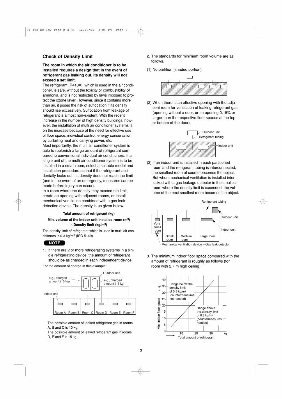
2. The standards for minimum room volume are asfollows.
(1) No partition (shaded portion)
(2) When there is an effective opening with the adja-cent room for ventilation of leaking refrigerant gas(opening without a door, or an opening 0.15% orlarger than the respective floor spaces at the topor bottom of the door).
(3) If an indoor unit is installed in each partitionedroom and the refrigerant tubing is interconnected,the smallest room of course becomes the object.But when mechanical ventilation is installed inter-locked with a gas leakage detector in the smallestroom where the density limit is exceeded, the vol-ume of the next smallest room becomes the object.
3. The minimum indoor floor space compared with theamount of refrigerant is roughly as follows (forroom with 2.7 m high ceiling):
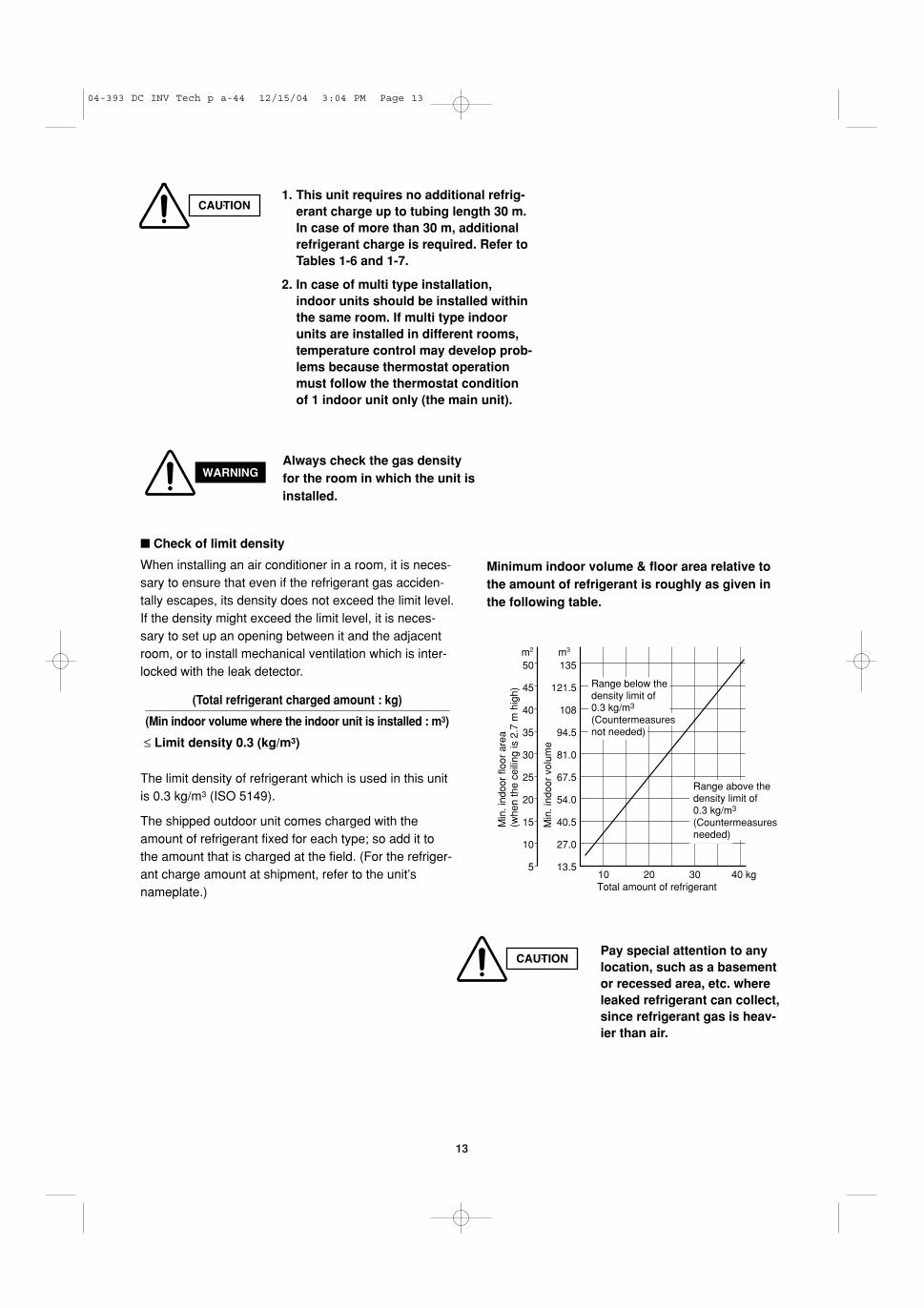
Check of Density Limit
The room in which the air conditioner is to beinstalled requires a design that in the event ofrefrigerant gas leaking out, its density will notexceed a set limit.The refrigerant (R410A), which is used in the air condi-tioner, is safe, without the toxicity or combustibility ofammonia, and is not restricted by laws imposed to pro-tect the ozone layer. However, since it contains morethan air, it poses the risk of suffocation if its densityshould rise excessively. Suffocation from leakage ofrefrigerant is almost non-existent. With the recentincrease in the number of high density buildings, how-ever, the installation of multi air conditioner systems ison the increase because of the need for effective useof floor space, individual control, energy conservationby curtailing heat and carrying power, etc.Most importantly, the multi air conditioner system isable to replenish a large amount of refrigerant com-pared to conventional individual air conditioners. If asingle unit of the multi air conditioner system is to beinstalled in a small room, select a suitable model andinstallation procedure so that if the refrigerant acci-dentally leaks out, its density does not reach the limit(and in the event of an emergency, measures can bemade before injury can occur).In a room where the density may exceed the limit,create an opening with adjacent rooms, or installmechanical ventilation combined with a gas leakdetection device. The density is as given below.
Total amount of refrigerant (kg)
Min. volume of the indoor unit installed room (m3)≤ Density limit (kg/m3)
The density limit of refrigerant which is used in multi air con-ditioners is 0.3 kg/m3 (ISO 5149).
1. If there are 2 or more refrigerating systems in a sin-gle refrigerating device, the amount of refrigerantshould be as charged in each independent device.
For the amount of charge in this example:
The possible amount of leaked refrigerant gas in roomsA, B and C is 10 kg.The possible amount of leaked refrigerant gas in roomsD, E and F is 15 kg.
NOTE
Outdoor unit
Refrigerant tubing
Indoor unit
e.g., charged amount (10 kg)
Outdoor unit
Indoor unit
Room A Room B Room C Room D Room E Room F
e.g., charged amount (15 kg)
Refrigerant tubing
Outdoor unit
Very small room Indoor unit
Small room
Medium room
Large room
Mechanical ventilation device – Gas leak detector
40
35
30
25
20
15
10
5
010 20 30
Total amount of refrigerant
Min
. ind
oor
floor
spa
ce
m2
kg
Range below the density limit of 0.3 kg/m3
(countermeasures not needed)
Range above the density limit of 0.3 kg/m3
(countermeasures needed)
04-393 DC INV Tech p a-44 12/15/04 3:04 PM Page 3
4
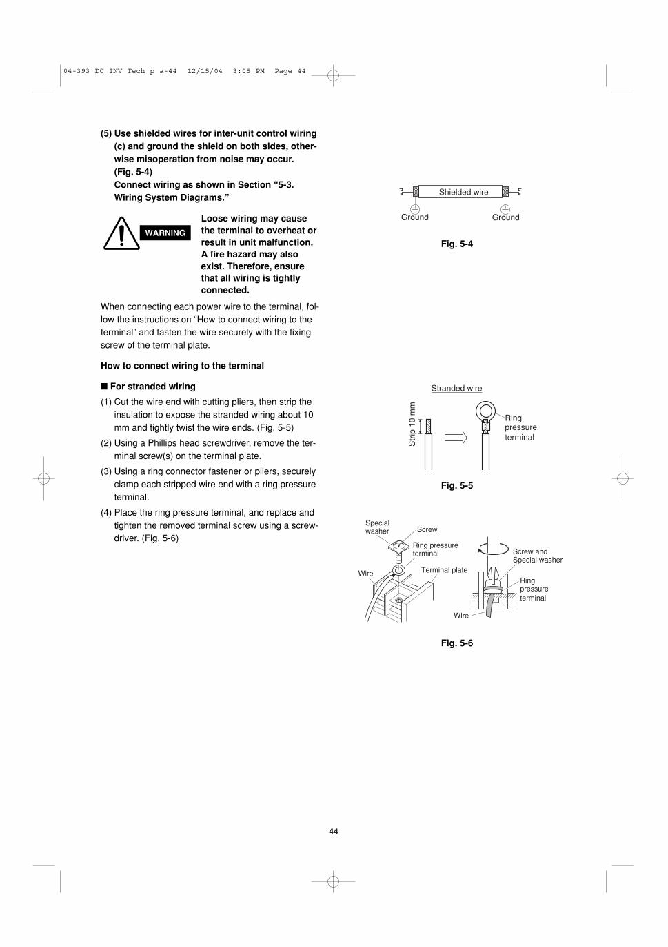
1-2. Prevent impurities including water, dust and oxide from entering the tubing. Impurities can cause R410Arefrigerant deterioration and compressor defects. Due to the features of the refrigerant and refrigeratingmachine oil, the prevention of water and other impurities becomes more important than ever.
2. Be sure to recharge the refrigerant only in liquid form.
2-1. Since R410A is a non-azeotrope, recharging the refrigerant in gas form can lower performance and causedefects of the unit.
2-2. Since refrigerant composition changes and performance decreases when gas leaks, collect the remainingrefrigerant and recharge the required total amount of new refrigerant after fixing the leak.
3. Different tools required
3-1. Tool specifications have been changed due to the characteristics of R410A.Some tools for R22- and R407C-type refrigerant systems cannot be used.
Unit: mm
Material 0
Copper tubeOuter diameter 6.35 9.52 12.7 15.88
Wall thickness 0.8 0.8 0.8 1.0
Item New R407C tools Remarkstool compatible
with R410A
Manifold gauge Yes No Types of refrigerant, refrigerating machineoil, and pressure gauge are different.
Charge hose Yes No To resist higher pressure, material must be changed.
Vacuum pump Yes Yes Use a conventional vacuum pump if it is equippedwith a check valve. If it has no check valve,purchase and attach a vacuum pump adapter.
Leak detector Yes No Leak detectors for CFC and HCFC that react to chlorine do not function because R410A contains no chlorine. Leak detectors for HFC134a can be used for R410A.
Flaring oil Yes No For systems that use R22, apply mineral oil (Suniso oil) to the flare nuts on the tubing to prevent refrigerant leakage. For machines that use R407C or R410A, apply synthetic oil (ether oil) to the flare nuts.
Precautions for Installation Using New Refrigerant
1. Care regarding tubing
1-1. Process tubing
� Material: Use C1220 phosphorous deoxidized copper specified in JIS H3300 “Copper and Copper Alloy Seam-less Pipes and Tubes.”
� Tubing size: Be sure to use the sizes indicated in the table below.
� Use a tube cutter when cutting the tubing, and be sure to remove any flash. This also applies to distributionjoints (optional).
� When bending tubing φ15.88 or smaller, use a bending radius that is 4 times the outer diameter of the tubing or larger.
* Using tools for R22 and R407C and new tools for R410A together can cause defects.
Manifold gauge
Vacuum pump
OutletInlet
CAUTIONUse sufficient care in handling the tubing. Seal the tubing ends withcaps or tape to prevent dirt, moisture, or other foreign substancesfrom entering. These contaminants can result in system malfunction.
04-393 DC INV Tech p a-44 12/15/04 3:04 PM Page 4
5
Valve
Liquid
3-2. Use R410A exclusive cylinder only.
Single-outlet valve
(with siphon tube)Liquid refrigerant should be rechargedwith the cylinder standing on end asshown.
04-393 DC INV Tech p a-44 12/15/04 3:04 PM Page 5
6
IMPORTANT . . . . . . . . . . . . . . . . . . . . . . . . . . . . . . 2Please Read Before StartingCheck of Density LimitPrecautions for Installation Using New Refrigerant
1. GENERAL . . . . . . . . . . . . . . . . . . . . . . . . . . . . . 81-1. Tools Required for Installation (not supplied)1-2. Accessories Supplied with Unit1-3. Type of Copper Tube and Insulation Material1-4. Additional Materials Required for Installation1-5. Tubing Size1-6. Optional Distribution Joint Kits1-7. Installing Distribution Joint Kit (for Twin &
Double-Twin) (K70A056Z)1-8. Installing Distribution Joint Kit (for Triple)
(K70A061Z)
2. SELECTING THE INSTALLATION SITE . . . . .172-1. Indoor Unit2-2. Outdoor Unit2-3. Air Discharge Chamber for Top Discharge2-4. Installing the Unit in Heavy Snow Areas2-5. Precautions for Installation in Heavy Snow
Areas2-6. Dimensions of Snow / Wind-proof Ducting
and Refrigerant Tubing Space of Installation
3. HOW TO INSTALL THE INDOOR UNIT . . . . .20
� 4-Way Air Discharge Semi-Concealed Type (CAFP Type) . . . . . . . . . . . . . . . . . . . . . . . . . . .203-1. Preparation for Suspending 3-2. Suspending the Indoor Unit3-3. Placing the Unit Inside the Ceiling 3-4. Installing the Drain Piping3-5. Checking the Drainage
� Wall-Mounted Type (MAFP Type) . . . . . . . . . . .243-6. Removing the Rear Panel from the Unit3-7. Selecting and Making a Hole3-8. Installing the Rear Panel onto the Wall3-9. Removing the Grille to Install the Indoor Unit3-10. Preparing the Tubing 3-11. Shaping the Tubing3-12. Installing the Drain Hose
� Ceiling-Mounted Type (SPAFP Type) . . . . . . . .283-13. Required Minimum Space for Installation and
Service3-14. Suspending the Indoor Unit3-15. Duct for Fresh Air3-16. Shaping the Tubing3-17. Installing the Drain Piping
� Concealed-Duct Type (DSAFP Type) . . . . . . .353-18. Required Minimum Space for Installation and
Service
3-19. Suspending the Indoor Unit 3-20. Installing the Drain Piping 3-21. Checking the Drainage 3-22. Increasing the Fan Speed
4. HOW TO INSTALL THE OUTDOOR UNIT . . .404-1. Installing the Outdoor Unit4-2. Drainage Work4-3. Routing the Tubing and Wiring
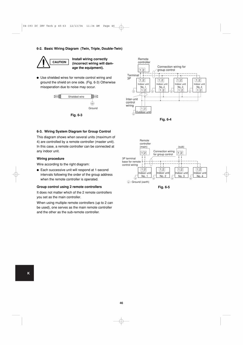
eter for Power Supply System 5-3. Wiring System Diagrams
6. HOW TO INSTALL THE REMOTE CONTROLLER(OPTIONAL PART) . . . . . . . . . . . . . . . . . . . . . .456-1. When Using a Wall Box for Flush Mounting 6-2. Basic Wiring Diagram (Twin, Triple, Double-
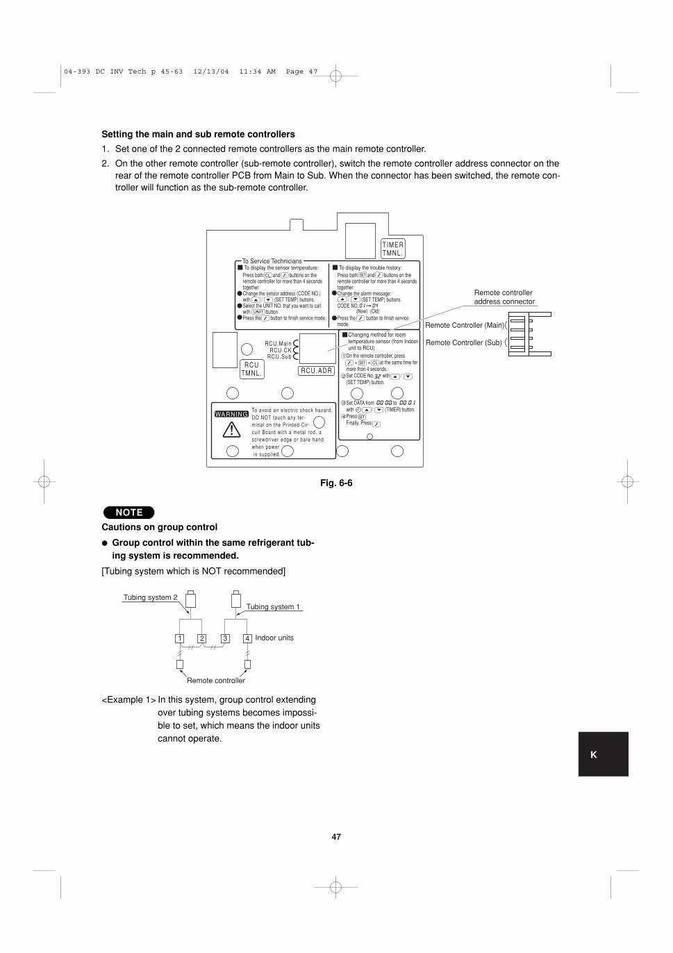
Twin)6-3. Wiring System Diagram for Group Control 6-4. Switching the Room Temperature Sensors6-5. Connecting to a Ventilation Fan6-6. Wiring the Remote Controller6-7. Trouble Diagnostics
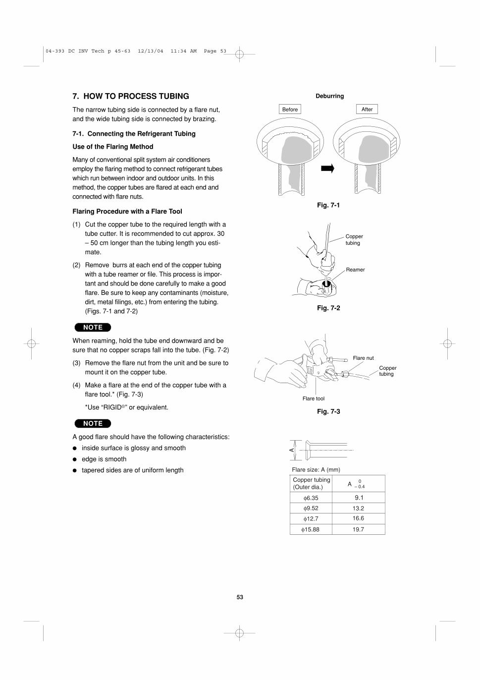
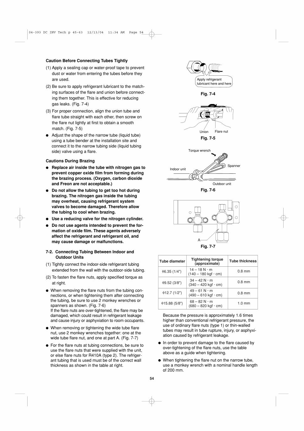
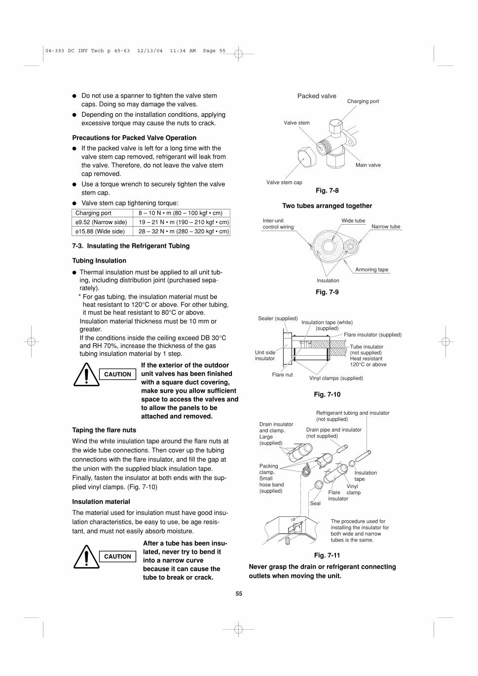
7. HOW TO PROCESS TUBING . . . . . . . . . . . . .537-1. Connecting the Refrigerant Tubing7-2. Connecting Tubing Between Indoor and
Outdoor Units7-3. Insulating the Refrigerant Tubing7-4. Taping the Tubes7-5. Finishing the Installation
� Air Purging with a Vacuum Pump (for Test Run)Preparation . . . . . . . . . . . . . . . . . . . . . . . . . . . 578-1. Leak Test8-2. Evacuation8-3. Charging Additional Refrigerant8-4. Finishing the Job
9. HOW TO INSTALL THE CEILING PANEL . . . .60
� 4-Way Air Discharge Semi-Concealed Type (CAFP Type) . . . . . . . . . . . . . . . . . . . . . . . . . . 609-1. Before Installing the Ceiling Panel 9-2. Installing the Ceiling Panel 9-3. Wiring the Ceiling Panel9-4. How to Attach the Corner & Air Intake Grille9-5. Checking After Installation9-6. When Removing the Ceiling Panel for Servicing9-7. Adjusting the Auto Flap
CONTENTS
Page Page
04-393 DC INV Tech p a-44 12/15/04 3:04 PM Page 6
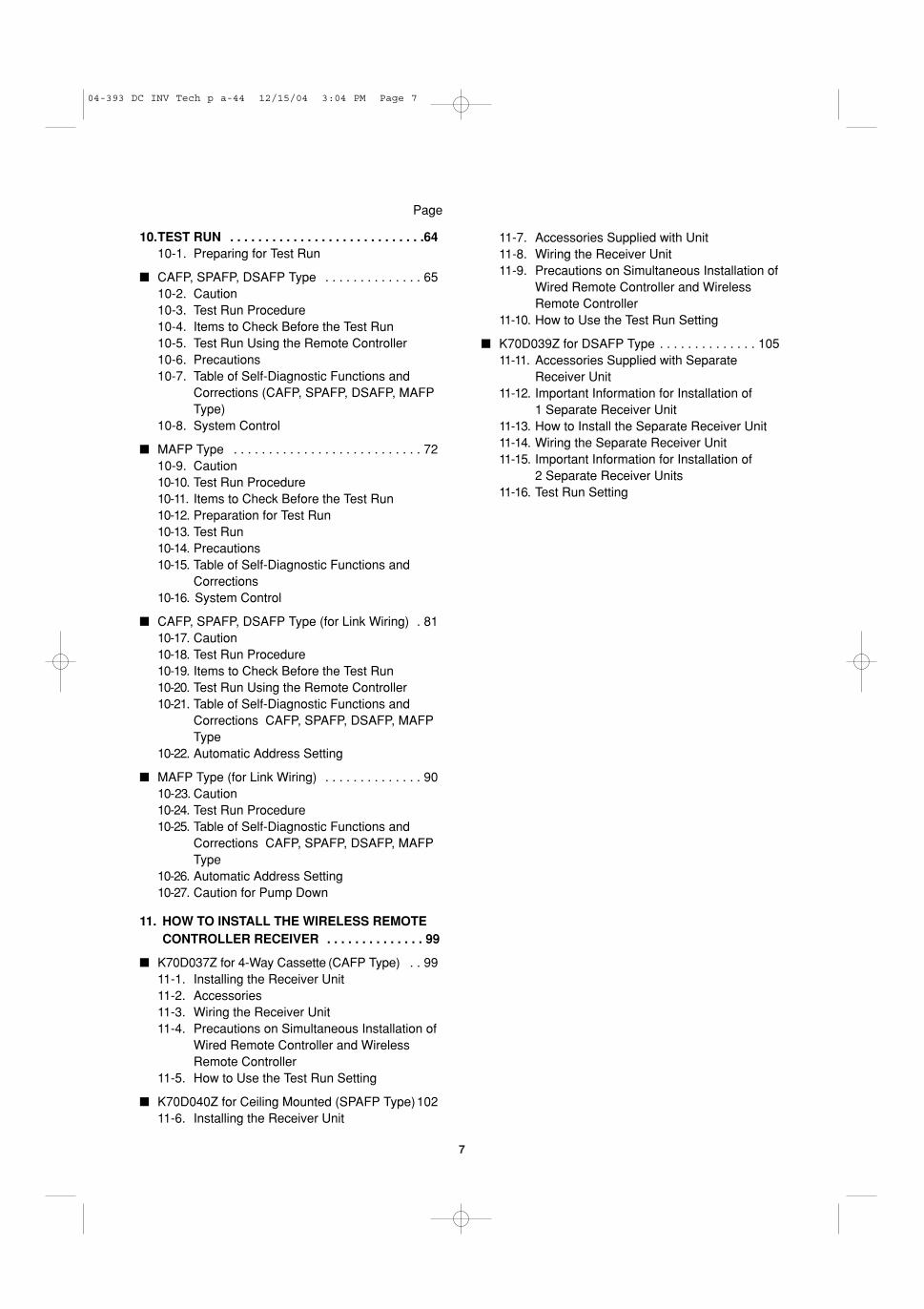
7
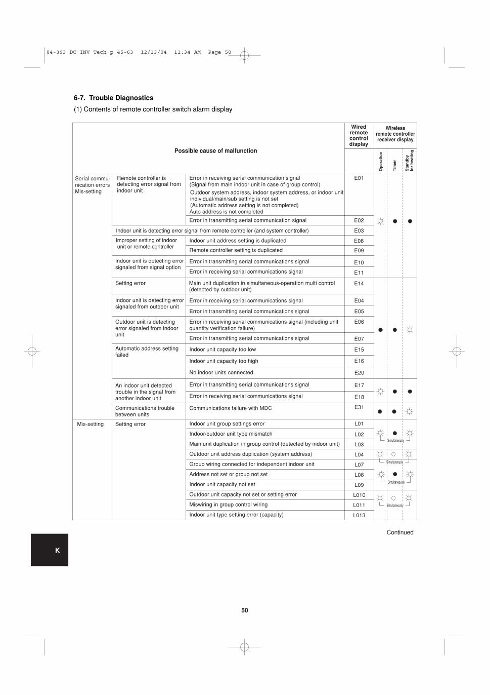
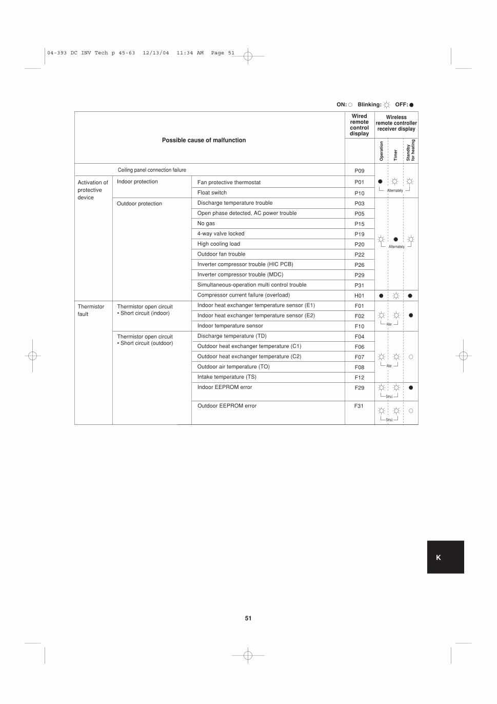
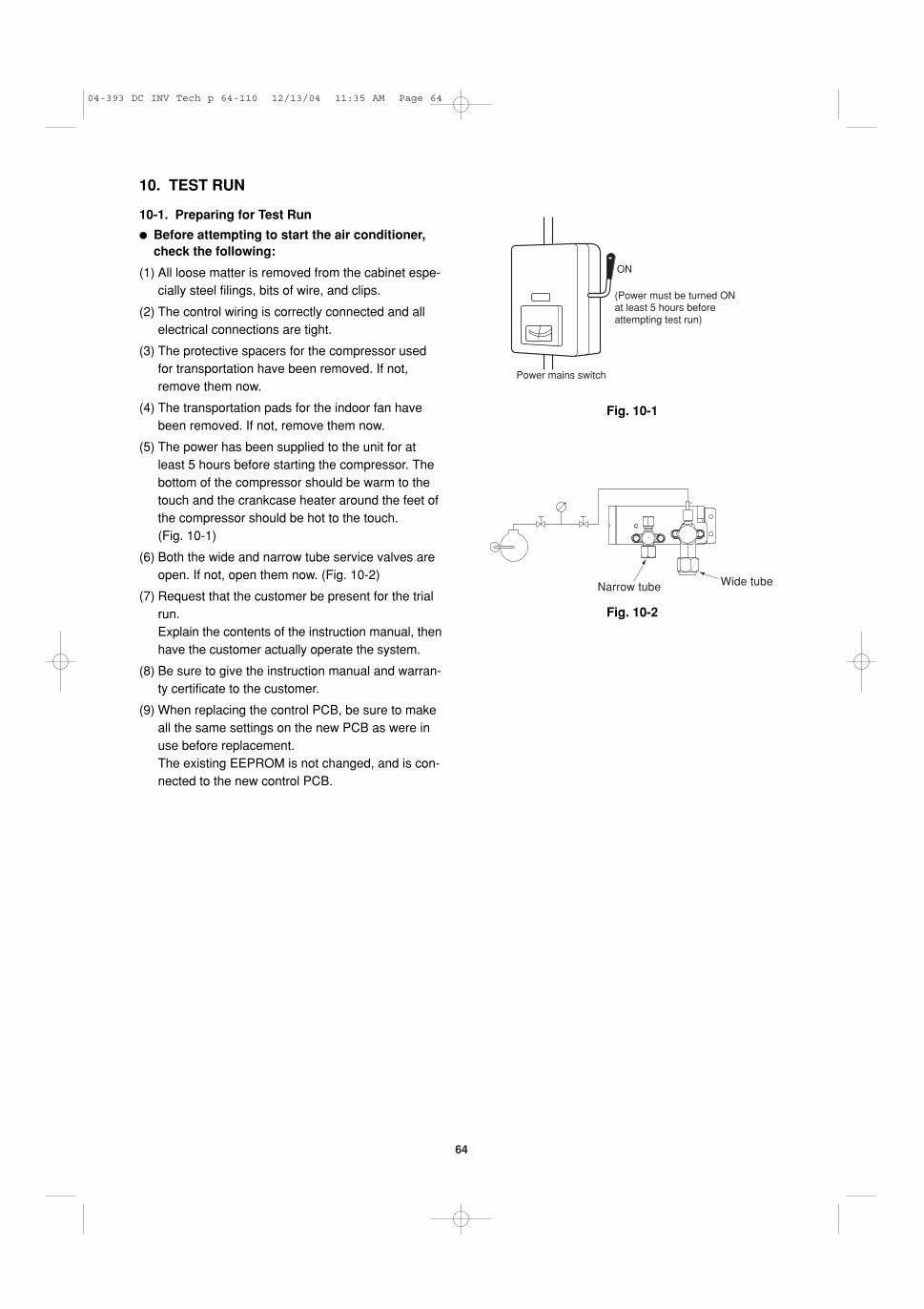
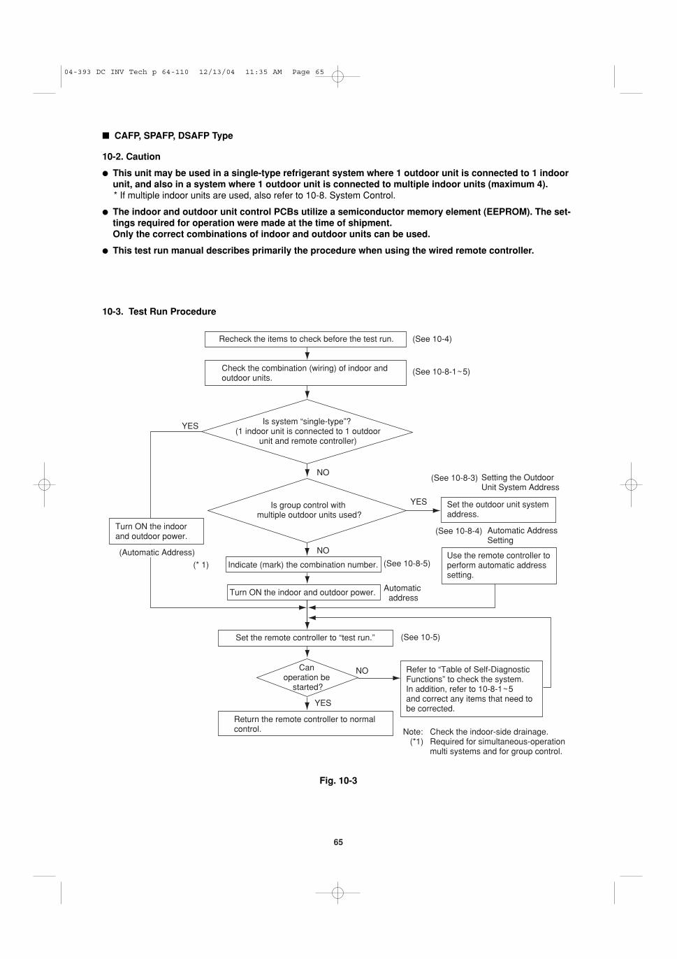
10.TEST RUN . . . . . . . . . . . . . . . . . . . . . . . . . . . .6410-1. Preparing for Test Run
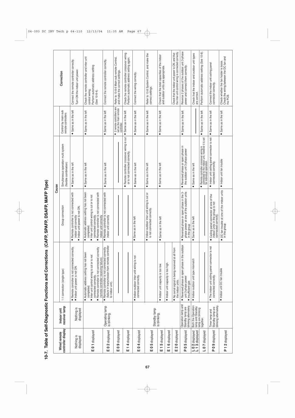
� CAFP, SPAFP, DSAFP Type . . . . . . . . . . . . . . 6510-2. Caution10-3. Test Run Procedure10-4. Items to Check Before the Test Run10-5. Test Run Using the Remote Controller10-6. Precautions10-7. Table of Self-Diagnostic Functions and
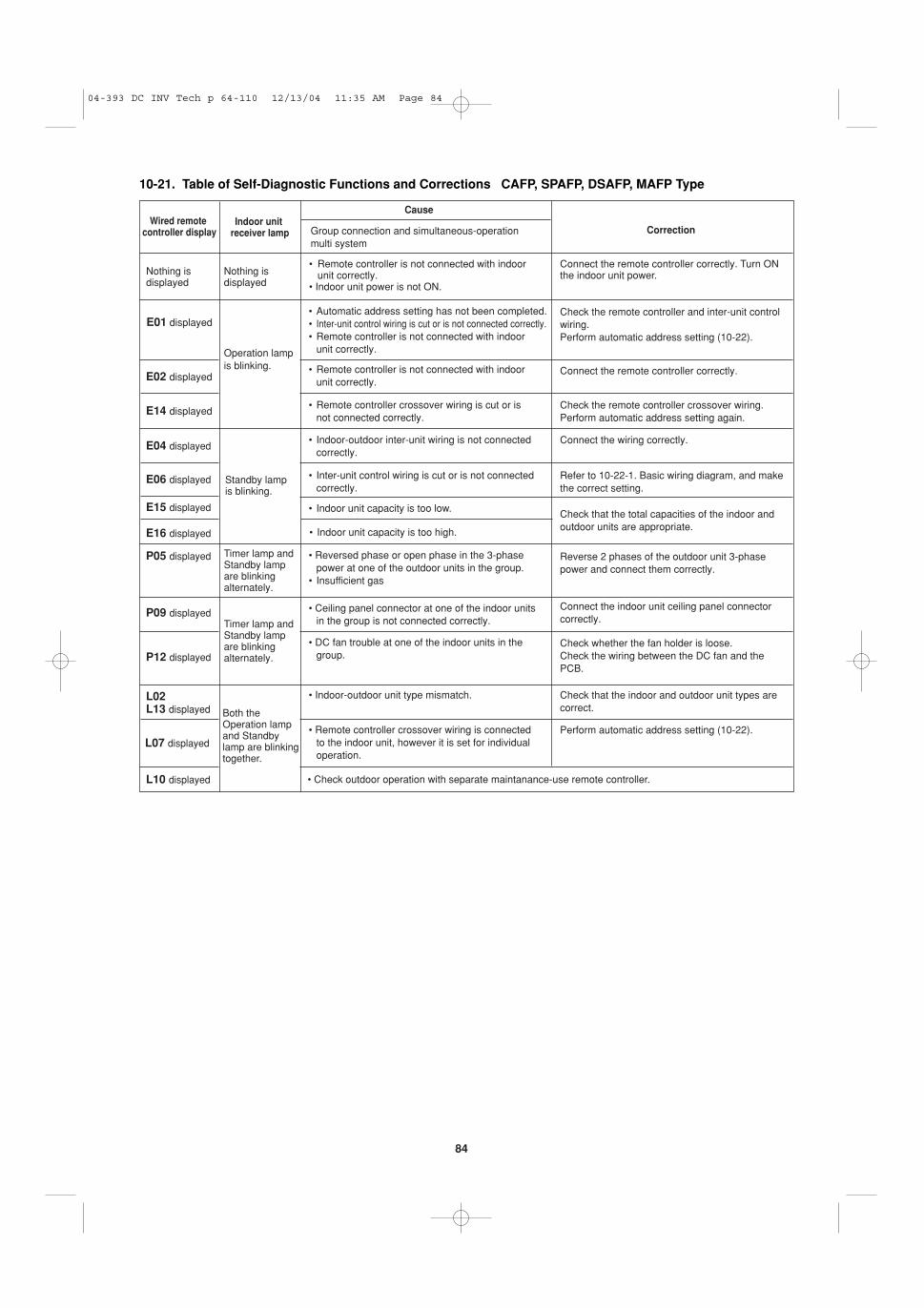
Corrections (CAFP, SPAFP, DSAFP, MAFPType)
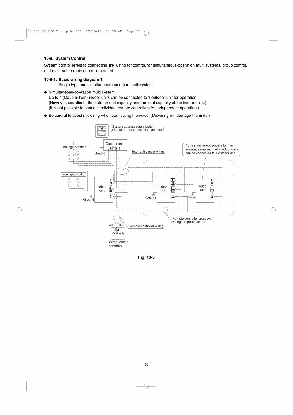
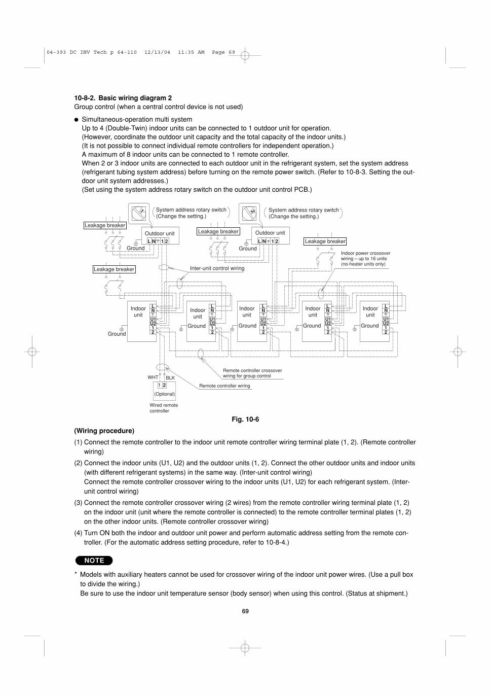
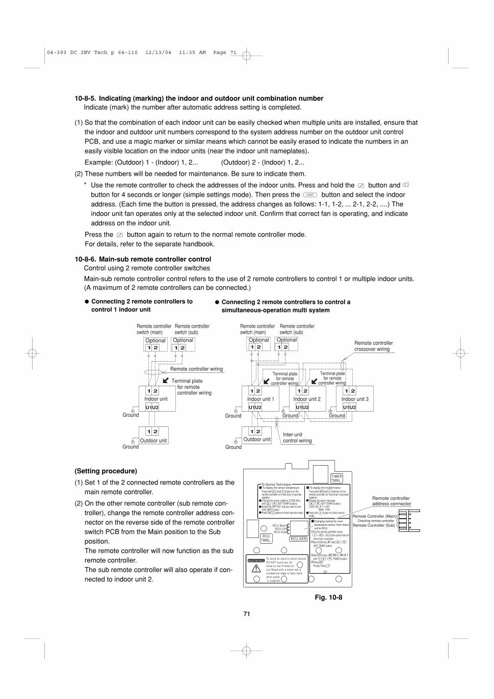
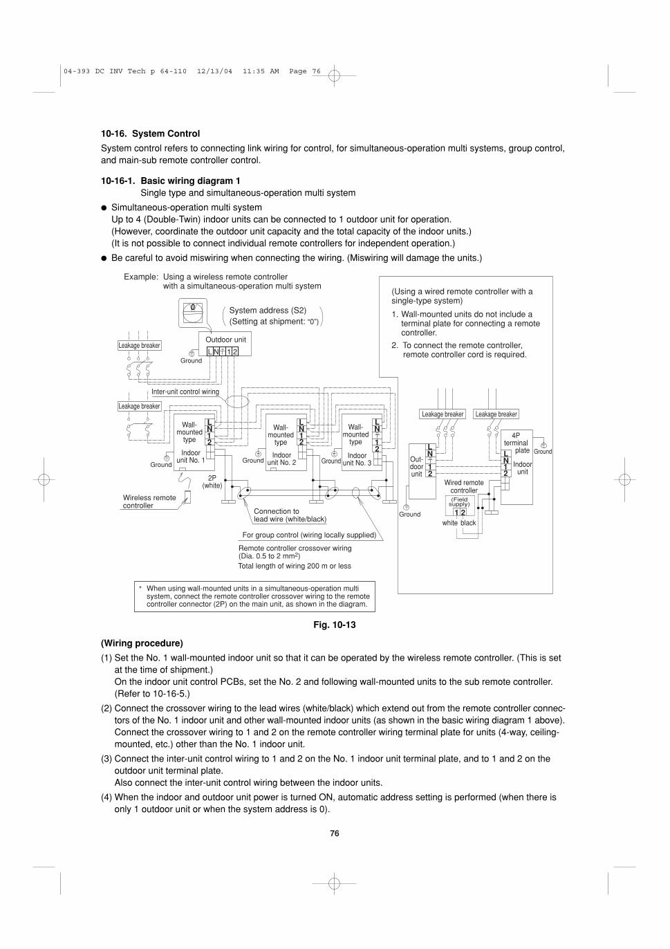
10-8. System Control
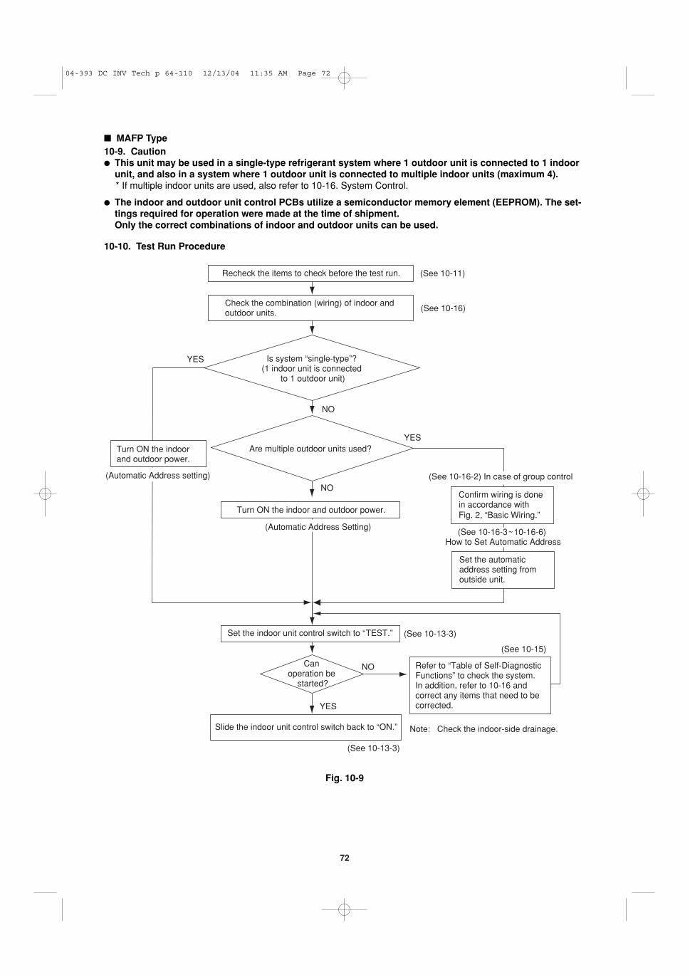
� MAFP Type . . . . . . . . . . . . . . . . . . . . . . . . . . . 7210-9. Caution10-10. Test Run Procedure10-11. Items to Check Before the Test Run10-12. Preparation for Test Run10-13. Test Run10-14. Precautions10-15. Table of Self-Diagnostic Functions and
Corrections 10-16. System Control
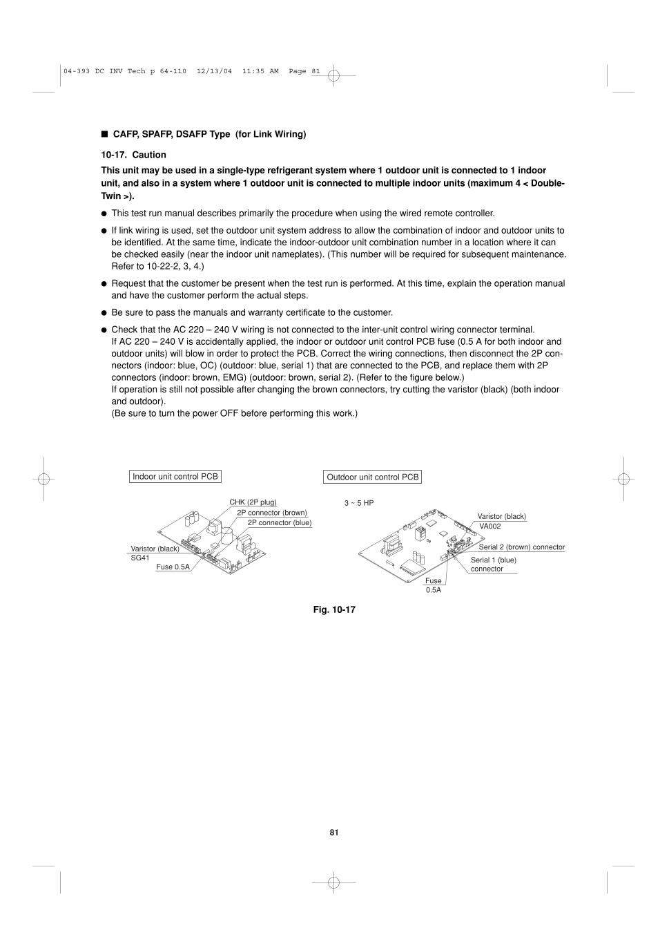
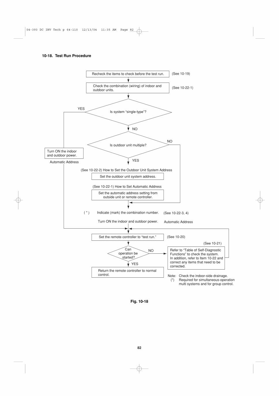
� CAFP, SPAFP, DSAFP Type (for Link Wiring) . 8110-17. Caution10-18. Test Run Procedure10-19. Items to Check Before the Test Run10-20. Test Run Using the Remote Controller10-21. Table of Self-Diagnostic Functions and
Corrections CAFP, SPAFP, DSAFP, MAFPType
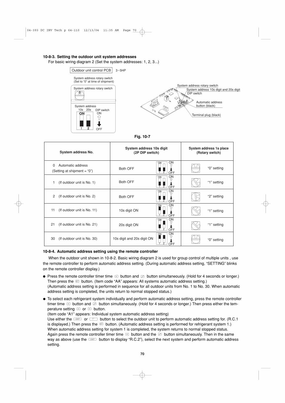
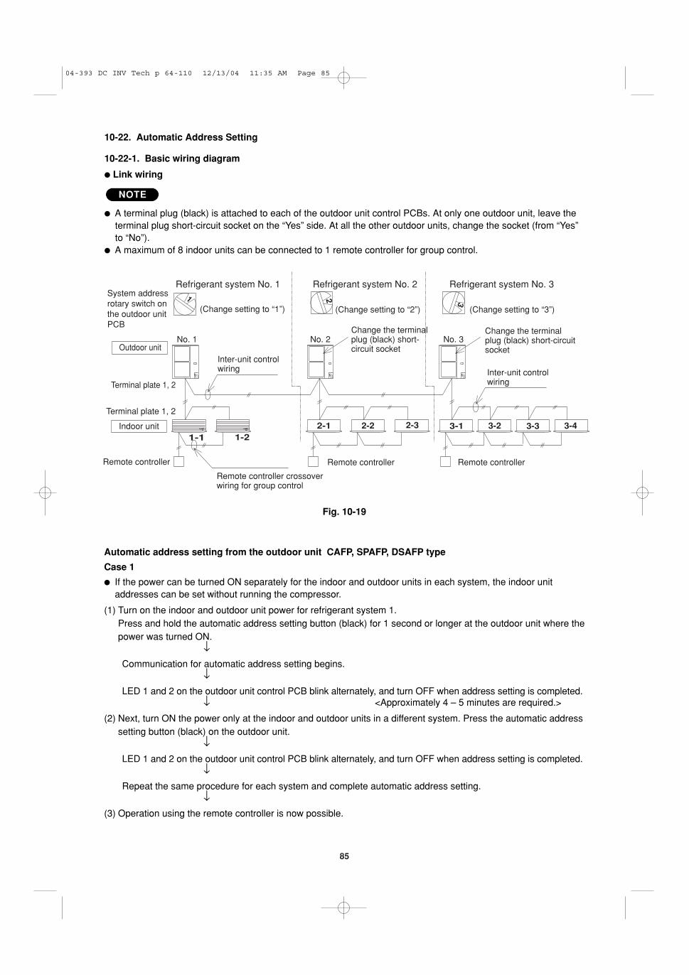
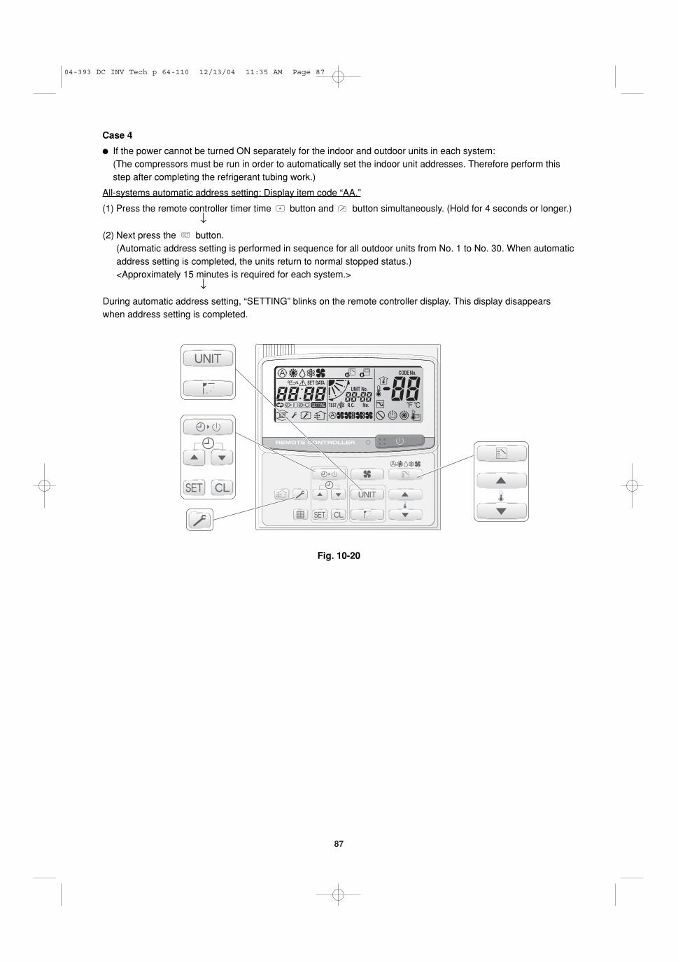
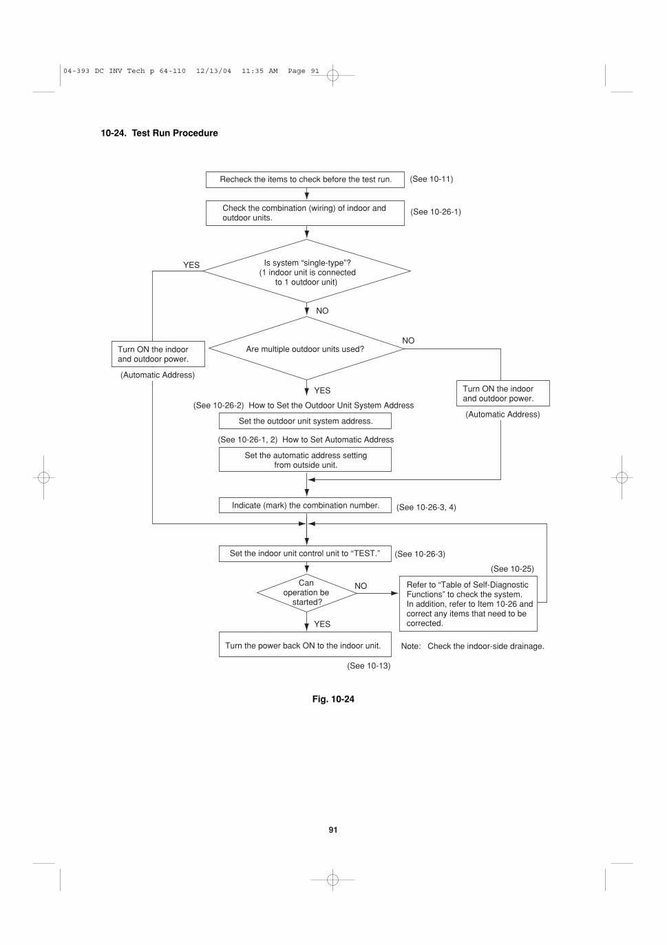
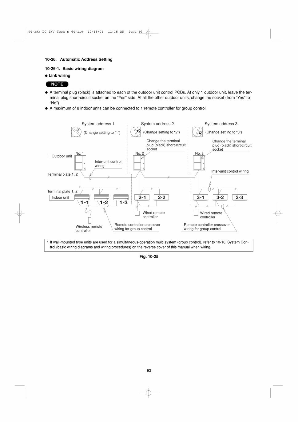
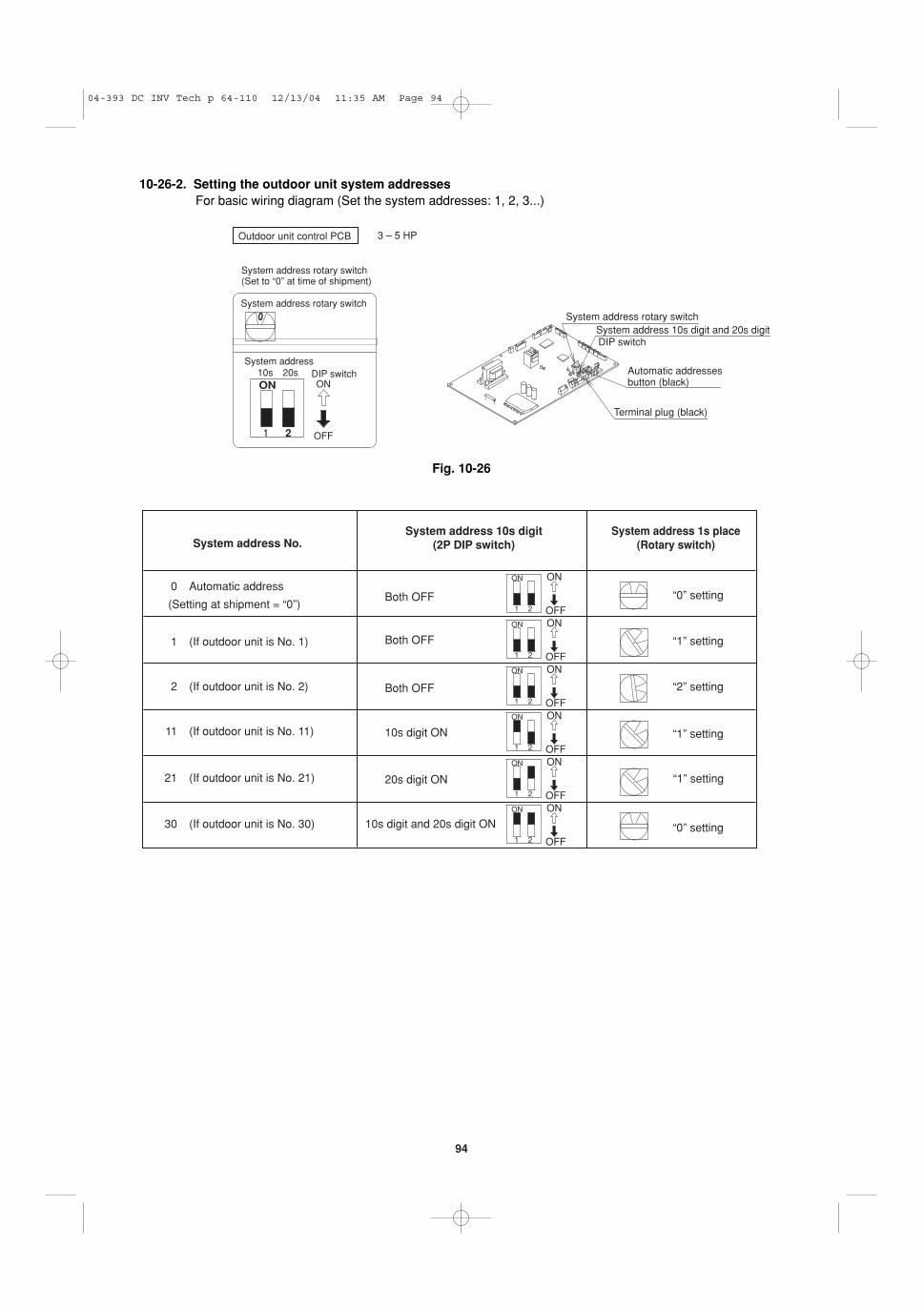
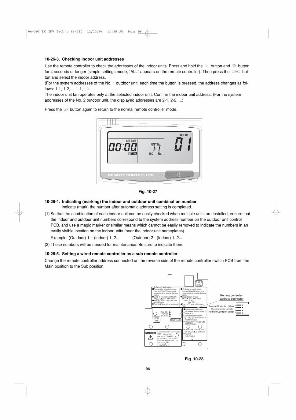
10-22. Automatic Address Setting
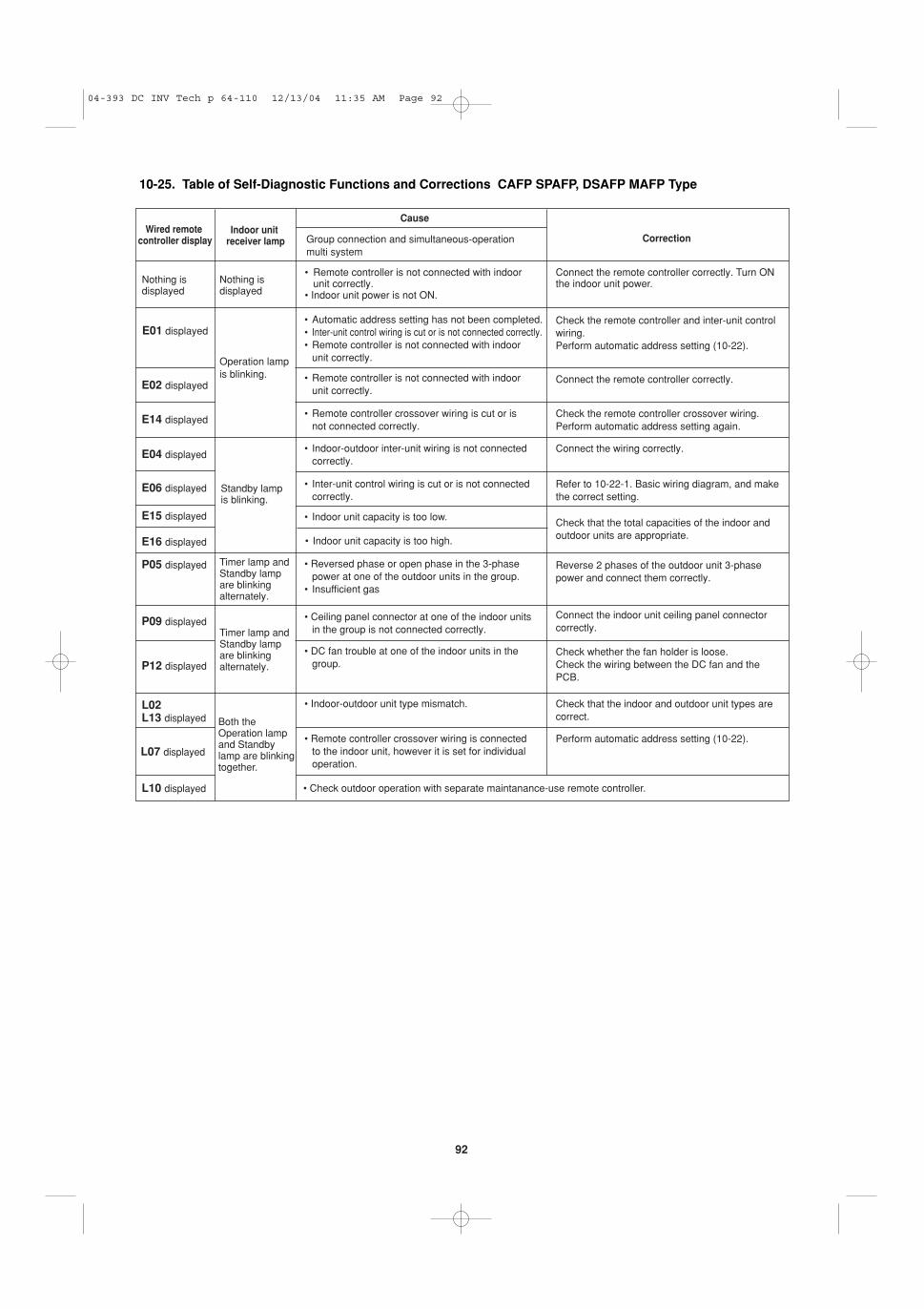
� MAFP Type (for Link Wiring) . . . . . . . . . . . . . . 9010-23. Caution10-24. Test Run Procedure10-25. Table of Self-Diagnostic Functions and
Corrections CAFP, SPAFP, DSAFP, MAFPType
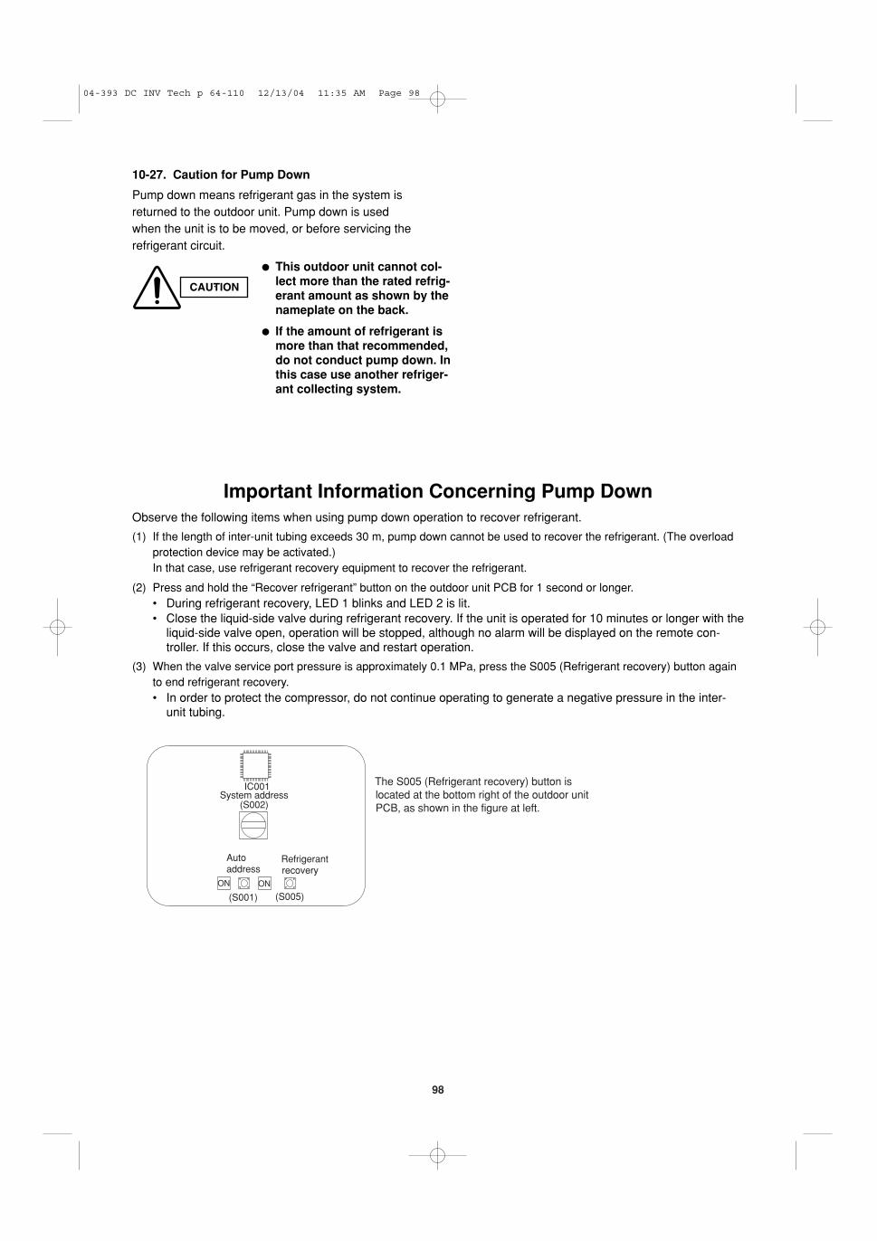
10-26. Automatic Address Setting10-27. Caution for Pump Down
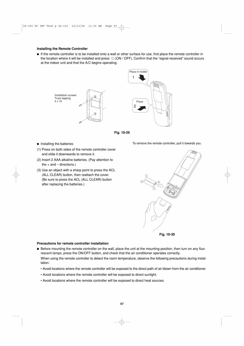
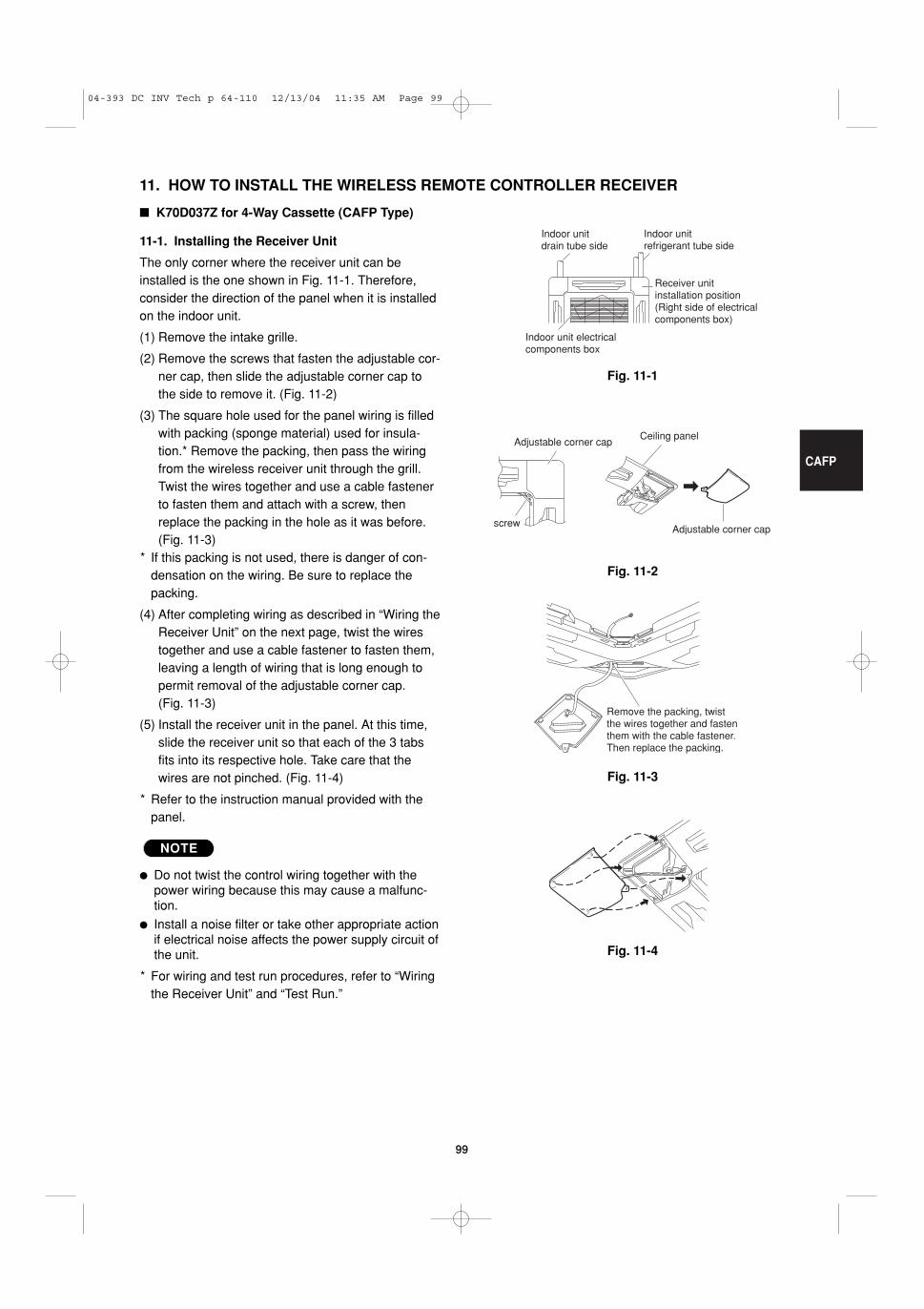
11. HOW TO INSTALL THE WIRELESS REMOTE CONTROLLER RECEIVER . . . . . . . . . . . . . . 99
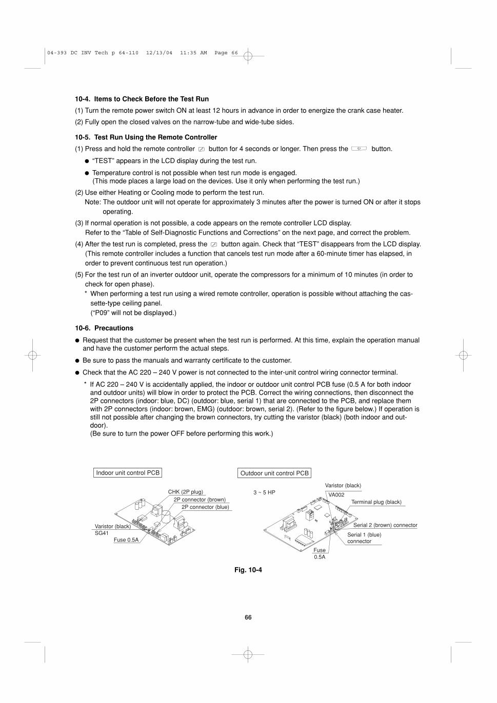
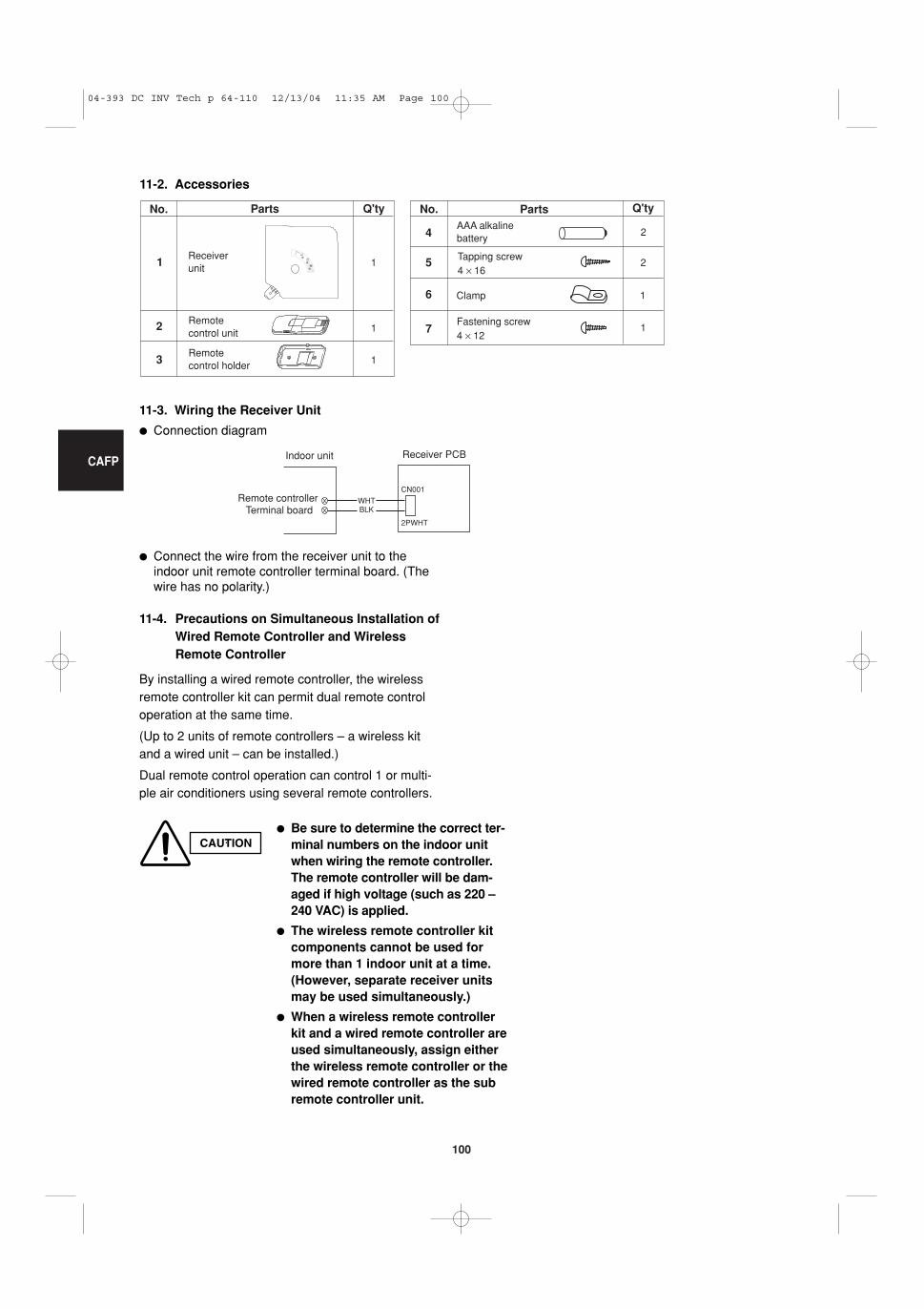
� K70D037Z for 4-Way Cassette (CAFP Type) . . 9911-1. Installing the Receiver Unit11-2. Accessories11-3. Wiring the Receiver Unit11-4. Precautions on Simultaneous Installation of
Wired Remote Controller and WirelessRemote Controller
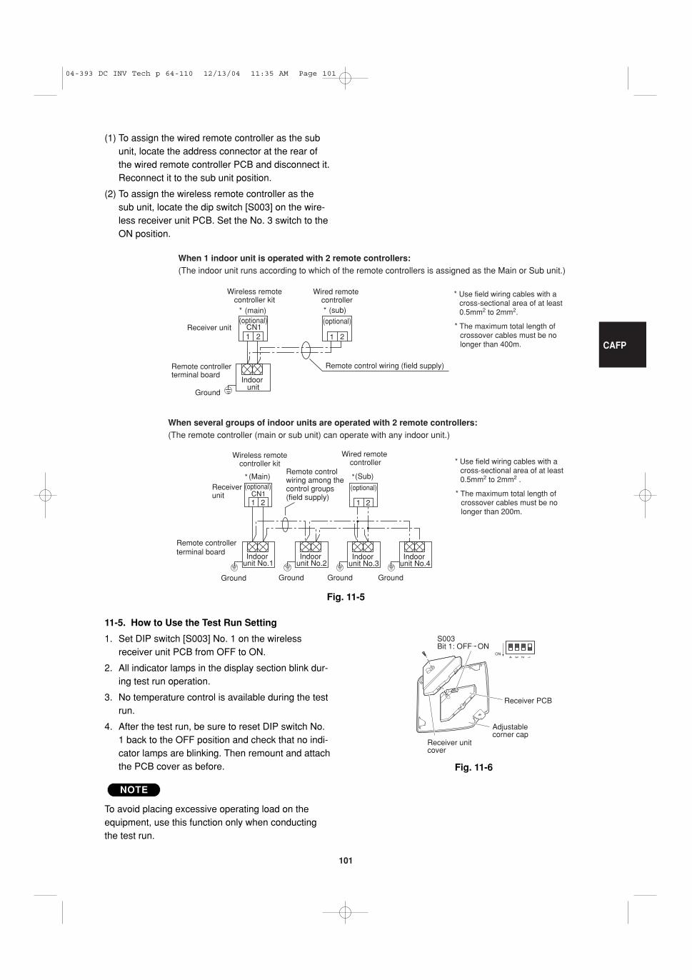
11-5. How to Use the Test Run Setting
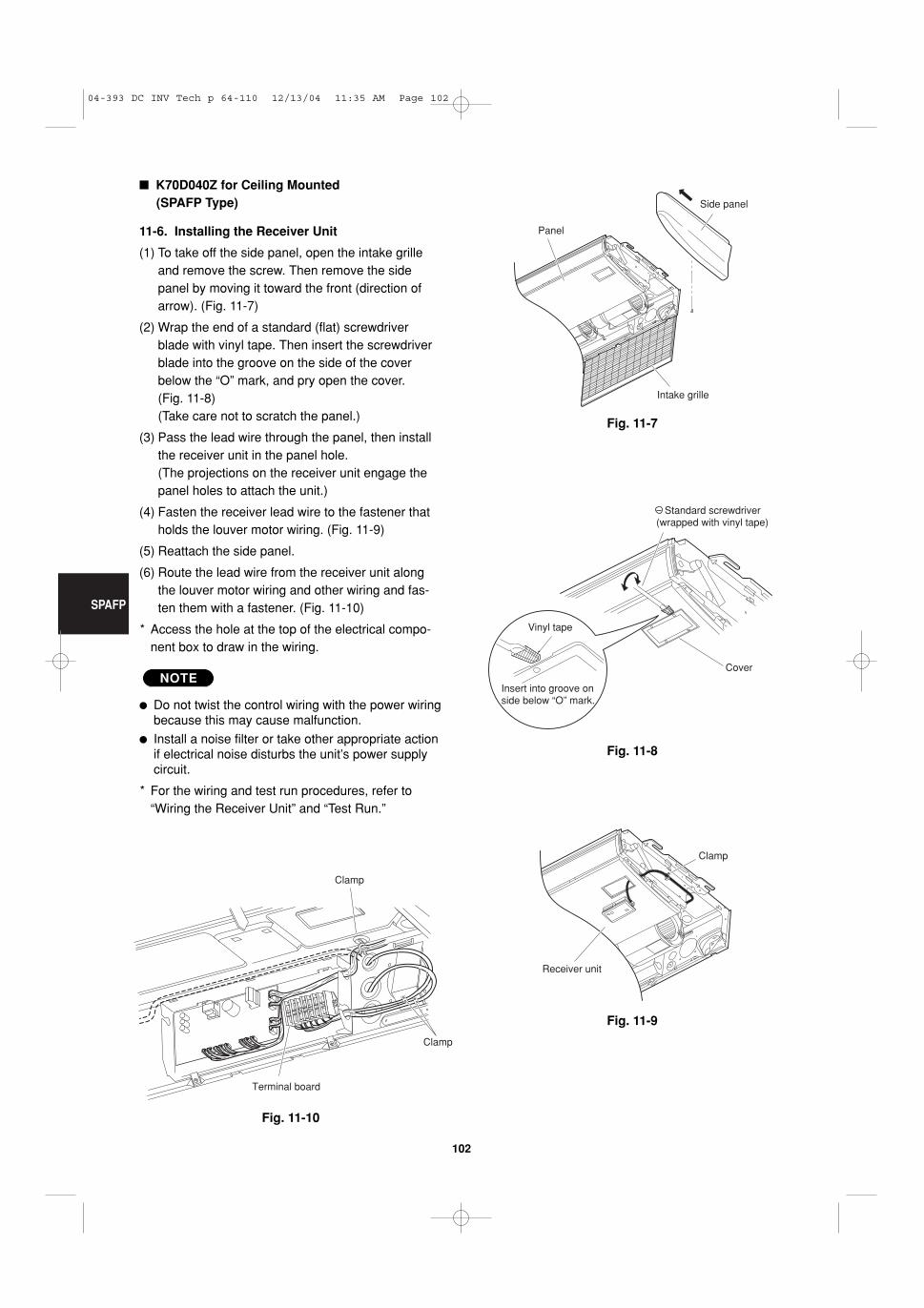
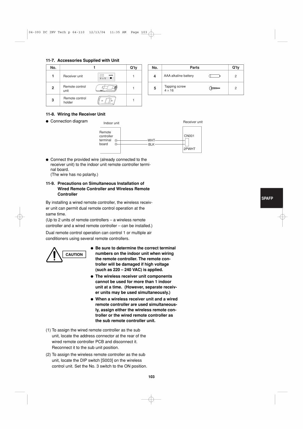
� K70D040Z for Ceiling Mounted (SPAFP Type)10211-6. Installing the Receiver Unit
11-7. Accessories Supplied with Unit11-8. Wiring the Receiver Unit11-9. Precautions on Simultaneous Installation of
Wired Remote Controller and WirelessRemote Controller
11-10. How to Use the Test Run Setting
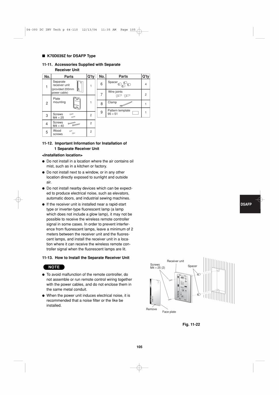
� K70D039Z for DSAFP Type . . . . . . . . . . . . . . 10511-11. Accessories Supplied with Separate
Receiver Unit 11-12. Important Information for Installation of
1 Separate Receiver Unit11-13. How to Install the Separate Receiver Unit 11-14. Wiring the Separate Receiver Unit11-15. Important Information for Installation of
2 Separate Receiver Units11-16. Test Run Setting
Page
04-393 DC INV Tech p a-44 12/15/04 3:04 PM Page 7
8
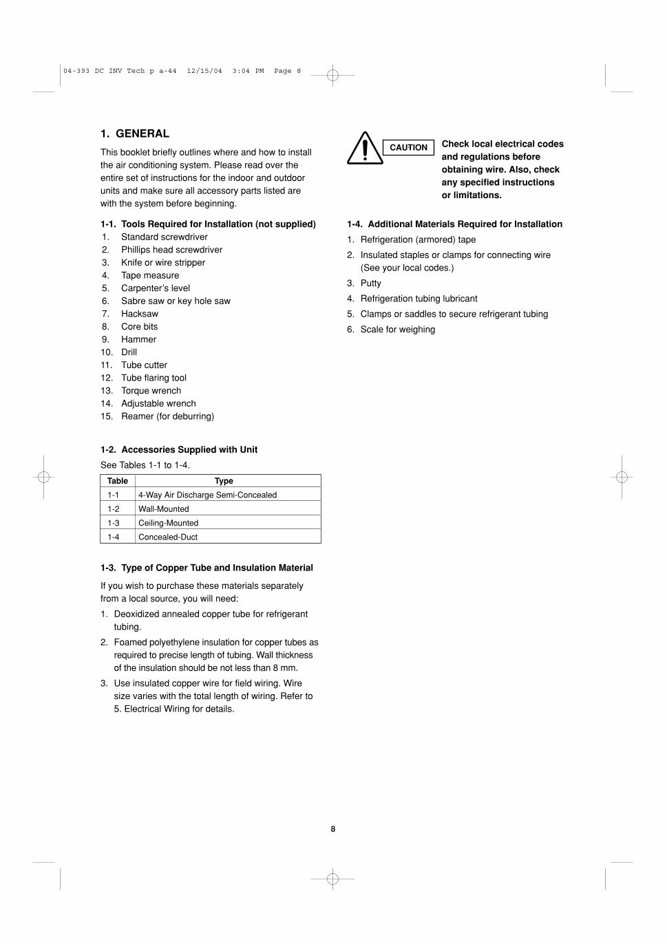
1. GENERAL
This booklet briefly outlines where and how to installthe air conditioning system. Please read over theentire set of instructions for the indoor and outdoorunits and make sure all accessory parts listed arewith the system before beginning.
1-1. Tools Required for Installation (not supplied)1. Standard screwdriver2. Phillips head screwdriver3. Knife or wire stripper4. Tape measure5. Carpenter’s level6. Sabre saw or key hole saw7. Hacksaw8. Core bits9. Hammer10. Drill11. Tube cutter12. Tube flaring tool13. Torque wrench14. Adjustable wrench15. Reamer (for deburring)
1-2. Accessories Supplied with Unit
See Tables 1-1 to 1-4.
1-3. Type of Copper Tube and Insulation Material
If you wish to purchase these materials separatelyfrom a local source, you will need:
1. Deoxidized annealed copper tube for refrigeranttubing.
2. Foamed polyethylene insulation for copper tubes asrequired to precise length of tubing. Wall thicknessof the insulation should be not less than 8 mm.
3. Use insulated copper wire for field wiring. Wiresize varies with the total length of wiring. Refer to5. Electrical Wiring for details.
1-4. Additional Materials Required for Installation
1. Refrigeration (armored) tape
2. Insulated staples or clamps for connecting wire(See your local codes.)
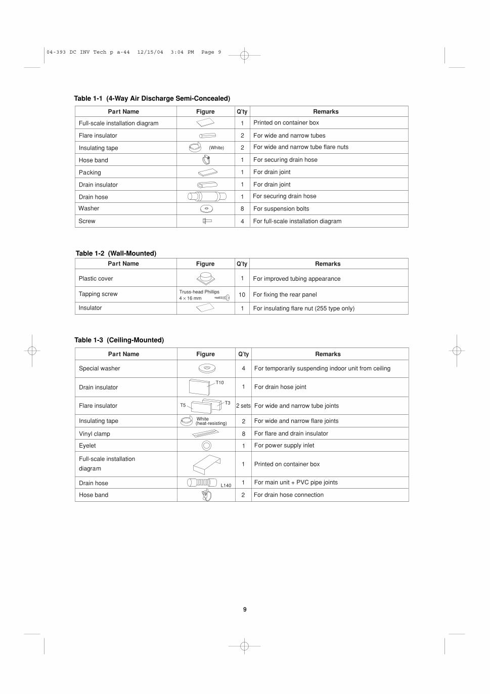
Table 1-2 (Wall-Mounted)Part Name Figure Q’ty Remarks
Plastic cover 1
Tapping screw 10
For improved tubing appearance
For fixing the rear panelTruss-head Phillips4 × 16 mm
Insulator 1 For insulating flare nut (255 type only)
Table 1-3 (Ceiling-Mounted)
Part Name Figure Q’ty Remarks
Special washer 4
Drain insulator 1
Flare insulator 2 sets
Insulating tape 2
Vinyl clamp 8
Eyelet 1
Full-scale installation
diagram1
Drain hose 1
For temporarily suspending indoor unit from ceiling
For drain hose joint
For wide and narrow tube joints
For wide and narrow flare joints
For flare and drain insulator
For power supply inlet
T10
T5 T3
White(heat-resisting)
For drain hose connection2Hose band
L140For main unit + PVC pipe joints
Printed on container box
04-393 DC INV Tech p a-44 12/15/04 3:04 PM Page 9
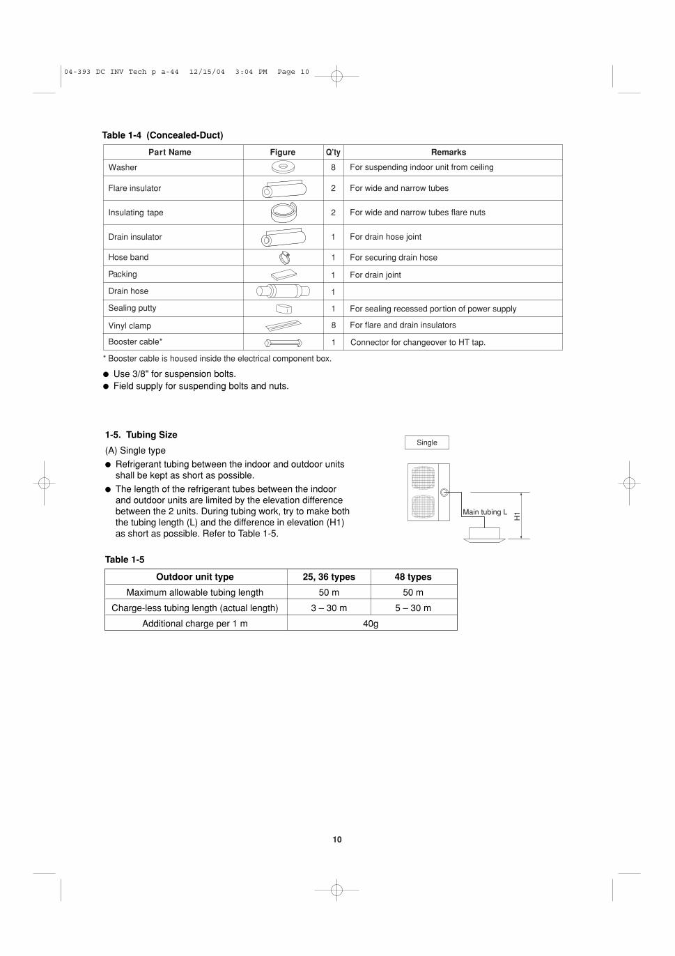
10
Table 1-4 (Concealed-Duct)
Part Name Figure Q’ty Remarks
8
Flare insulator 2
Insulating tape 2
Drain insulator 1
Hose band 1
Packing 1
Drain hose 1
Sealing putty 1
Vinyl clamp 8
Booster cable* 1
For suspending indoor unit from ceiling
For wide and narrow tubes
For wide and narrow tubes flare nuts
For drain hose joint
For securing drain hose
For drain joint
For sealing recessed portion of power supply
For flare and drain insulators
* Booster cable is housed inside the electrical component box.
Washer
Connector for changeover to HT tap.
� Use 3/8" for suspension bolts.� Field supply for suspending bolts and nuts.
1-5. Tubing Size
(A) Single type
� Refrigerant tubing between the indoor and outdoor unitsshall be kept as short as possible.
� The length of the refrigerant tubes between the indoorand outdoor units are limited by the elevation differencebetween the 2 units. During tubing work, try to make boththe tubing length (L) and the difference in elevation (H1)as short as possible. Refer to Table 1-5.
Table 1-5
Single
Main tubing LH
1
Outdoor unit type 25, 36 types 48 types
Maximum allowable tubing length 50 m 50 m
Charge-less tubing length (actual length) 3 – 30 m 5 – 30 m
Additional charge per 1 m 40g
04-393 DC INV Tech p a-44 12/15/04 3:04 PM Page 10
11
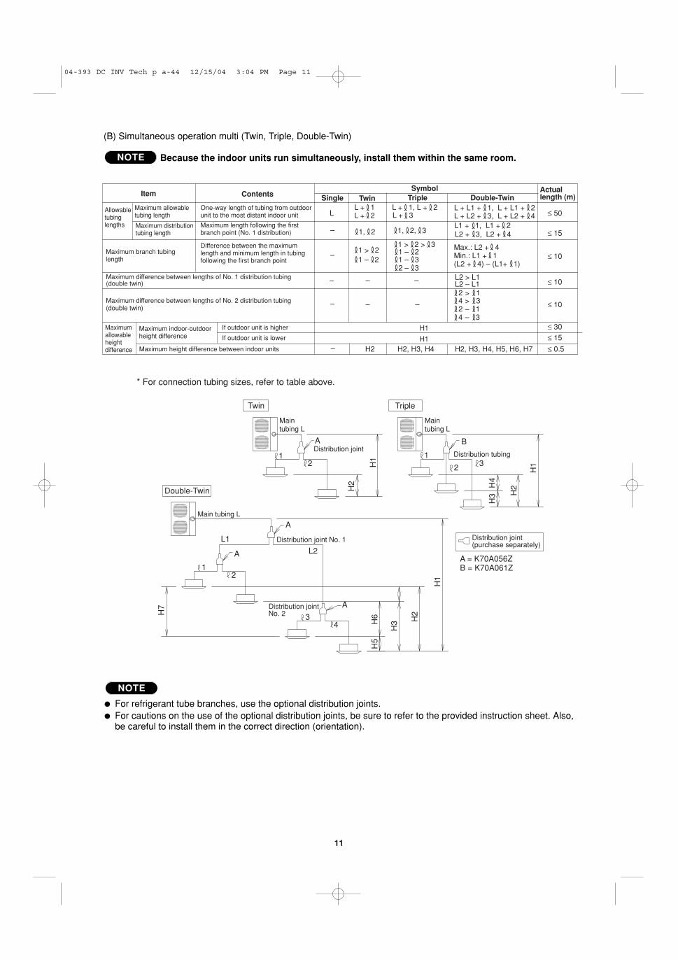
(B) Simultaneous operation multi (Twin, Triple, Double-Twin)
Because the indoor units run simultaneously, install them within the same room.NOTE
Single Twin Triple Double-TwinActual length (m)
LL + 1L + 2 L + 3
L + 1, L + 2 L + L1 + 1, L + L1 + 2
L2 + 3, L2 + 4
Max.: L2 + 4Min.: L1 + 1(L2 + 4) – (L1+ 1)
L1 + 1, L1 + 21, 2
1 > 21 > 2 > 3
1 – 21 – 21 – 32 – 3
L + L2 + 3, L + L2 + 4
1, 2, 3
≤ 50
≤ 15
≤ 10
≤ 10
≤ 10
≤ 30
≤ 15
≤ 0.5
Item Contents
Allowable tubing lengths
Maximum allowable tubing length
One-way length of tubing from outdoor unit to the most distant indoor unit
Maximum distribution tubing length
Maximum length following the first branch point (No. 1 distribution)
Maximum branch tubing length
Difference between the maximum length and minimum length in tubing following the first branch point
Maximum difference between lengths of No. 1 distribution tubing (double twin)
Maximum difference between lengths of No. 2 distribution tubing (double twin)
Maximum allowable height difference
Maximum indoor-outdoor height difference
If outdoor unit is higher
If outdoor unit is lower
Maximum height difference between indoor units
Symbol
L2 > L1
2 > 1 4 > 3 2 – 1 4 – 3
L2 – L1
H2 H2, H3, H4 H2, H3, H4, H5, H6, H7
–
–
– – –
–
–
– –
H1
H1
TripleTwin
Double-Twin
Main tubing L
Main tubing L
Main tubing L
Distribution joint No. 1 Distribution joint (purchase separately)
Distribution joint Distribution tubing
A
A
A
12 2
A
1
1
2
3
3
4
* For connection tubing sizes, refer to table above.
B
H1
H1
H1
H2
H2
H2 H4
H3
H3H
6H7
H5
Distribution joint No. 2
L1
L2A = K70A056ZB = K70A061Z
� For refrigerant tube branches, use the optional distribution joints.� For cautions on the use of the optional distribution joints, be sure to refer to the provided instruction sheet. Also,
be careful to install them in the correct direction (orientation).
NOTE
04-393 DC INV Tech p a-44 12/15/04 3:04 PM Page 11
12
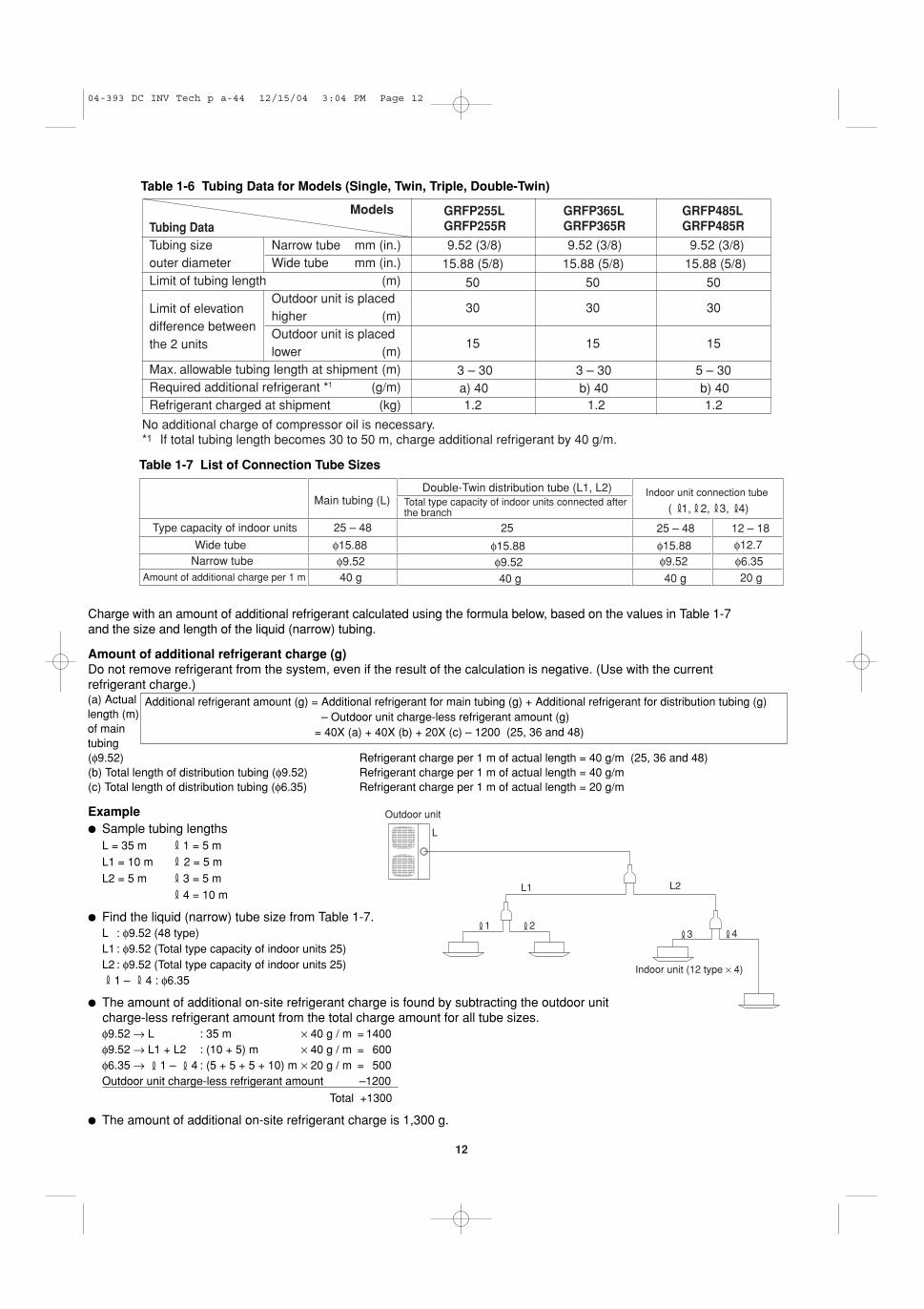
Limit of elevationdifference betweenthe 2 units
No additional charge of compressor oil is necessary.*1 If total tubing length becomes 30 to 50 m, charge additional refrigerant by 40 g/m.
Models GRFP255LGRFP255R
GRFP365LGRFP365R
GRFP485LGRFP485RTubing Data
Tubing size Narrow tube mm (in.) 9.52 (3/8) 9.52 (3/8) 9.52 (3/8)outer diameter Wide tube mm (in.) 15.88 (5/8) 15.88 (5/8) 15.88 (5/8)Limit of tubing length (m) 50 50 50
Outdoor unit is placed30 30 30
higher (m)Outdoor unit is placed
15 15 15lower (m)
Max. allowable tubing length at shipment (m) 3 – 30 3 – 30 5 – 30Required additional refrigerant *1 (g/m) a) 40 b) 40 b) 40Refrigerant charged at shipment (kg) 1.2 1.2 1.2
Table 1-6 Tubing Data for Models (Single, Twin, Triple, Double-Twin)
25 – 4825 – 48 12 – 18
φ15.88φ15.88φ15.88φ9.52φ9.52φ9.52 φ6.35
φ12.7
( 1, 2, 3, 4)
20 g40 g40 g40 g
Wide tubeNarrow tube
Main tubing (L)
25
Double-Twin distribution tube (L1, L2)Total type capacity of indoor units connected after the branch
Indoor unit connection tube
Type capacity of indoor units
Amount of additional charge per 1 m
Table 1-7 List of Connection Tube Sizes
Charge with an amount of additional refrigerant calculated using the formula below, based on the values in Table 1-7and the size and length of the liquid (narrow) tubing.
Amount of additional refrigerant charge (g)Do not remove refrigerant from the system, even if the result of the calculation is negative. (Use with the currentrefrigerant charge.)(a) Actuallength (m)of maintubing(φ9.52) Refrigerant charge per 1 m of actual length = 40 g/m (25, 36 and 48)(b) Total length of distribution tubing (φ9.52) Refrigerant charge per 1 m of actual length = 40 g/m(c) Total length of distribution tubing (φ6.35) Refrigerant charge per 1 m of actual length = 20 g/m
Example� Sample tubing lengths
L = 35 m 1 = 5 mL1 = 10 m 2 = 5 mL2 = 5 m 3 = 5 m
4 = 10 m
� Find the liquid (narrow) tube size from Table 1-7.L : φ9.52 (48 type)L1 : φ9.52 (Total type capacity of indoor units 25)L2 : φ9.52 (Total type capacity of indoor units 25)
1 – 4 : φ6.35
� The amount of additional on-site refrigerant charge is found by subtracting the outdoor unit charge-less refrigerant amount from the total charge amount for all tube sizes.φ9.52 → L : 35 m × 40 g / m = 1400φ9.52 → L1 + L2 : (10 + 5) m × 40 g / m = 600φ6.35 → 1 – 4 : (5 + 5 + 5 + 10) m × 20 g / m = 500Outdoor unit charge-less refrigerant amount –1200
Total +1300
� The amount of additional on-site refrigerant charge is 1,300 g.
Outdoor unit
Indoor unit (12 type × 4)
L
L1 L2
4321
Additional refrigerant amount (g) = Additional refrigerant for main tubing (g) + Additional refrigerant for distribution tubing (g) – Outdoor unit charge-less refrigerant amount (g)
04-393 DC INV Tech p a-44 12/15/04 3:04 PM Page 12
13
CAUTION
CAUTION
WARNING
1. This unit requires no additional refrig-erant charge up to tubing length 30 m.In case of more than 30 m, additionalrefrigerant charge is required. Refer toTables 1-6 and 1-7.
2. In case of multi type installation,indoor units should be installed withinthe same room. If multi type indoorunits are installed in different rooms,temperature control may develop prob-lems because thermostat operationmust follow the thermostat conditionof 1 indoor unit only (the main unit).
Always check the gas densityfor the room in which the unit isinstalled.
Pay special attention to anylocation, such as a basementor recessed area, etc. whereleaked refrigerant can collect,since refrigerant gas is heav-ier than air.
1013.5
27.0
40.5
54.0
67.5
81.0
94.5
108
121.5
135
5
10
15
20
25
30
35
40
45
50m3m2
Total amount of refrigerant
Min
. ind
oor
floor
are
a(w
hen
the
ceili
ng is
2.7
m h
igh)
Min
. ind
oor
volu
me
20 30 40 kg
Range below thedensity limit of 0.3 kg/m3
(Countermeasuresnot needed)
Range above thedensity limit of 0.3 kg/m3
(Countermeasuresneeded)
� Check of limit density
When installing an air conditioner in a room, it is neces-sary to ensure that even if the refrigerant gas acciden-tally escapes, its density does not exceed the limit level. If the density might exceed the limit level, it is neces-sary to set up an opening between it and the adjacentroom, or to install mechanical ventilation which is inter-locked with the leak detector.
(Total refrigerant charged amount : kg)
(Min indoor volume where the indoor unit is installed : m3)
≤ Limit density 0.3 (kg/m3)
The limit density of refrigerant which is used in this unitis 0.3 kg/m3 (ISO 5149).
The shipped outdoor unit comes charged with theamount of refrigerant fixed for each type; so add it tothe amount that is charged at the field. (For the refriger-ant charge amount at shipment, refer to the unit’snameplate.)
Minimum indoor volume & floor area relative tothe amount of refrigerant is roughly as given inthe following table.
04-393 DC INV Tech p a-44 12/15/04 3:04 PM Page 13
14
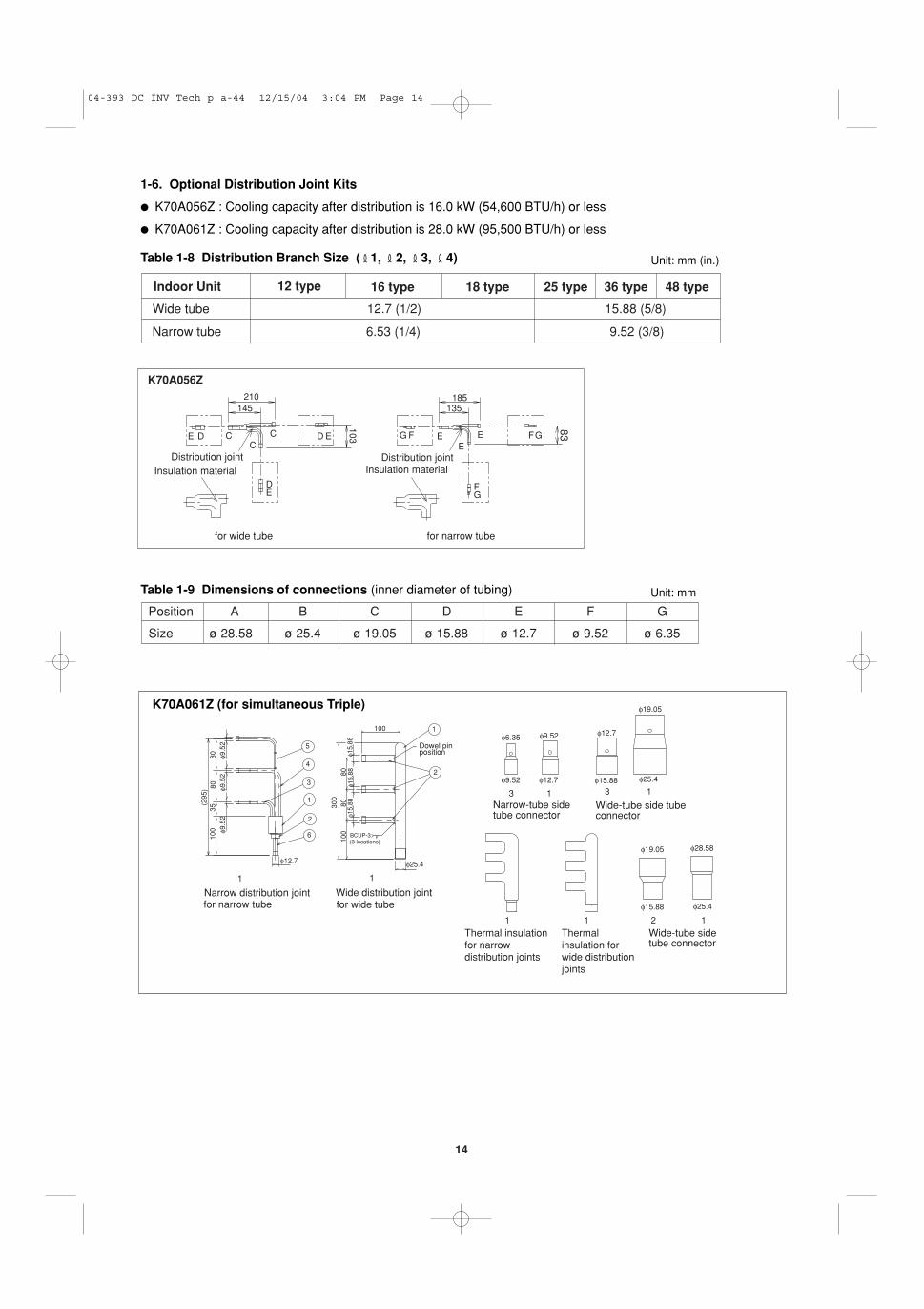
1-6. Optional Distribution Joint Kits
� K70A056Z : Cooling capacity after distribution is 16.0 kW (54,600 BTU/h) or less
� K70A061Z : Cooling capacity after distribution is 28.0 kW (95,500 BTU/h) or less
Table 1-8 Distribution Branch Size ( 1, 2, 3, 4) Unit: mm (in.)
Indoor Unit 12 type 16 type 18 type 25 type 36 type 48 type
Wide tube 12.7 (1/2) 15.88 (5/8)
Narrow tube 6.53 (1/4) 9.52 (3/8)
210145
103
185135
83
Distribution jointInsulation materialInsulation material
Distribution joint
E E E EE
E
D D
D
CC
C G G
G
F F
F
for wide tube for narrow tube
K70A056Z
Table 1-9 Dimensions of connections (inner diameter of tubing) Unit: mm
04-393 DC INV Tech p a-44 12/15/04 3:04 PM Page 14
15
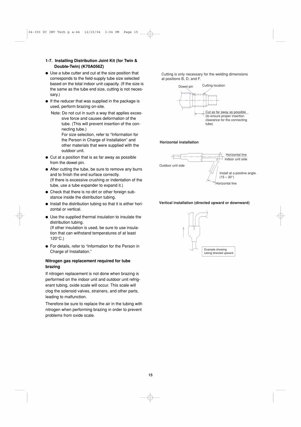
Dowel pin Cutting location
Cut as far away as possible (to ensure proper insertion clearance for the connecting tube)
Cutting is only necessary for the welding dimensions at positions B, D, and F.
Vertical installation (directed upward or downward)
Example showing tubing directed upward
Horizontal line
Horizontal line
Indoor unit side
Outdoor unit side
Install at a positive angle.(15 – 30°)
Horizontal installation
1-7. Installing Distribution Joint Kit (for Twin &Double-Twin) (K70A056Z)
� Use a tube cutter and cut at the size position thatcorresponds to the field-supply tube size selectedbased on the total indoor unit capacity. (If the size isthe same as the tube end size, cutting is not neces-sary.)
� If the reducer that was supplied in the package isused, perform brazing on-site.
Note: Do not cut in such a way that applies exces-sive force and causes deformation of thetube. (This will prevent insertion of the con-necting tube.) For size selection, refer to “Information forthe Person in Charge of Installation” andother materials that were supplied with theoutdoor unit.
� Cut at a position that is as far away as possiblefrom the dowel pin.
� After cutting the tube, be sure to remove any burrsand to finish the end surface correctly. (If there is excessive crushing or indentation of thetube, use a tube expander to expand it.)
� Check that there is no dirt or other foreign sub-stance inside the distribution tubing.
� Install the distribution tubing so that it is either hori-zontal or vertical.
� Use the supplied thermal insulation to insulate thedistribution tubing. (If other insulation is used, be sure to use insula-tion that can withstand temperatures of at least120°C.)
� For details, refer to “Information for the Person inCharge of Installation.”
Nitrogen gas replacement required for tube brazing
If nitrogen replacement is not done when brazing isperformed on the indoor unit and outdoor unit refrig-erant tubing, oxide scale will occur. This scale willclog the solenoid valves, strainers, and other parts,leading to malfunction.
Therefore be sure to replace the air in the tubing withnitrogen when performing brazing in order to preventproblems from oxide scale.
04-393 DC INV Tech p a-44 12/15/04 3:04 PM Page 15
16
Refrigerant tubing (field supply)
Refrigerant tubing (field supply)
Seal securely with vinyl tape (4 locations)
Distribution joint insulation materials (supplied)Use the supplied insulation materials.The supplied insulation materials include only tape for temporarily fastening them in place.Use insulation material or other material to seal the joining lines so that there are no gaps.Use vinyl tape or similar means to seal and fasten the insulation materials in place.
••
•
•
Tubing insulation material must be able to withstand temperatures of at least 120°C.
Tubing insulation material (field supply; thickness of more than 10 mm)
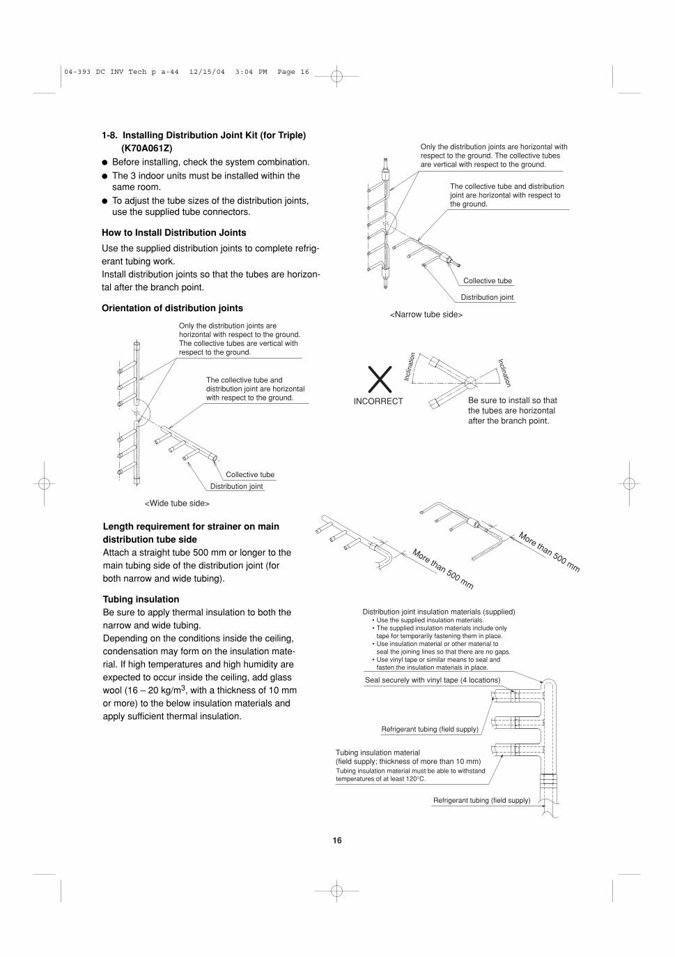
Only the distribution joints are horizontal with respect to the ground. The collective tubes are vertical with respect to the ground.
The collective tube and distribution joint are horizontal with respect to the ground.
Collective tube
Distribution joint
<Narrow tube side>
1-8. Installing Distribution Joint Kit (for Triple)(K70A061Z)
� Before installing, check the system combination.
� The 3 indoor units must be installed within thesame room.
� To adjust the tube sizes of the distribution joints,use the supplied tube connectors.
How to Install Distribution Joints
Use the supplied distribution joints to complete refrig-erant tubing work.Install distribution joints so that the tubes are horizon-tal after the branch point.
Orientation of distribution joints
Only the distribution joints are horizontal with respect to the ground. The collective tubes are vertical with respect to the ground.
The collective tube and distribution joint are horizontal with respect to the ground.
Collective tube
Distribution joint
<Wide tube side>
Incl
inat
ion Inclination
Be sure to install so that the tubes are horizontal after the branch point.
INCORRECT
Length requirement for strainer on maindistribution tube sideAttach a straight tube 500 mm or longer to themain tubing side of the distribution joint (forboth narrow and wide tubing).
Tubing insulationBe sure to apply thermal insulation to both thenarrow and wide tubing. Depending on the conditions inside the ceiling,condensation may form on the insulation mate-rial. If high temperatures and high humidity areexpected to occur inside the ceiling, add glasswool (16 – 20 kg/m3, with a thickness of 10 mmor more) to the below insulation materials andapply sufficient thermal insulation.
More than 500 mm
More than 500 mm
04-393 DC INV Tech p a-44 12/15/04 3:04 PM Page 16
17
2. SELECTING THE INSTALLATION SITE
2-1. Indoor Unit
AVOID:
� areas where leakage of flammable gas may beexpected.
� places where large amounts of oil mist exist.
� direct sunlight.
� locations near heat sources which may affect theperformance of the unit.
� locations where external air may enter the roomdirectly. This may cause “sweating” on the air dis-charge ports, causing them to spray or drip.
� locations where the remote controller will be splashedwith water or affected by dampness or humidity.
� installing the remote controller behind curtains or fur-niture.
� locations where high-frequency emissions are gener-ated.
DO:
� select an appropriate position from which every cor-ner of the room can be uniformly cooled.
� select a location where the ceiling is strong enoughto support the weight of the unit.
� select a location where tubing and drain pipe havethe shortest run to the outdoor unit.
� allow room for operation and maintenance as well asunrestricted air flow around the unit.
� install the unit within the maximum elevation differ-ence above or below the outdoor unit and within atotal tubing length (L) from the outdoor unit asdetailed in Tables 1-5 and 1-6.
� allow room for mounting the remote controller about1m off the floor, in an area that is not in direct sun-light nor in the flow of cool air from the indoor unit.
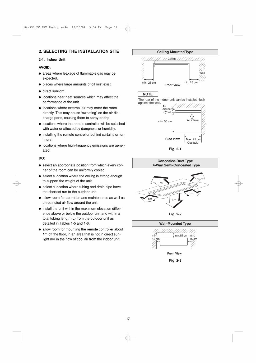
Concealed-Duct Type 4-Way Semi-Concealed Type
1m
1m 1m
1m
1m
Wall-Mounted Type
min.15 cm
Front View
min.15 cm
min.15 cm
Ceiling-Mounted Type
Side view
min. 25 cm
The rear of the indoor unit can be installed flushagainst the wall.
min. 50 cm Air intake
Airdischarge
min. 25 cm
Ceiling
Wall
NOTE
Front view
Max. 25 cmObstacle
Fig. 2-1
Fig. 2-2
Fig. 2-3
04-393 DC INV Tech p a-44 12/15/04 3:04 PM Page 17
18
2-2. Outdoor Unit
AVOID:
� heat sources, exhaust fans, etc. (Fig. 2-4)
� damp, humid or uneven locations
DO:
� choose a place as cool as possible.
� choose a place that is well ventilated and outsideair temperature does not exceed maximum 45°Cconstantly.
� allow enough room around the unit for air intake/exhaust and possible maintenance. (Fig. 2-5)
� use lag bolts or equal to bolt down unit, reducingvibration and noise.
Installation space
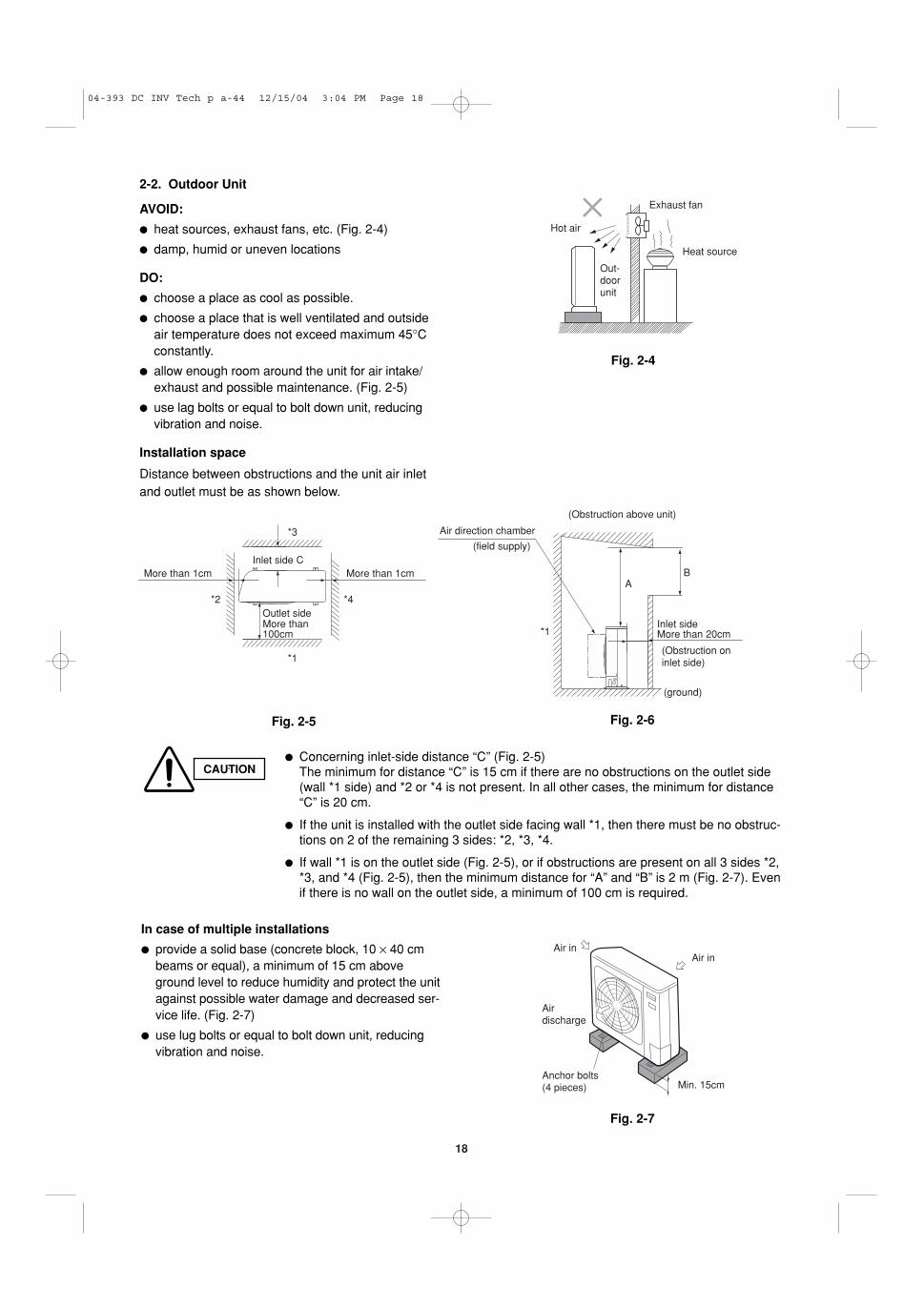
Distance between obstructions and the unit air inletand outlet must be as shown below.
Fig. 2-4
Fig. 2-5 Fig. 2-6
Fig. 2-7
Out-doorunit
Heat source
Hot air
Exhaust fan
Air inAir in
Airdischarge
Anchor bolts(4 pieces) Min. 15cm
In case of multiple installations
� provide a solid base (concrete block, 10 × 40 cmbeams or equal), a minimum of 15 cm aboveground level to reduce humidity and protect the unitagainst possible water damage and decreased ser-vice life. (Fig. 2-7)
� use lug bolts or equal to bolt down unit, reducingvibration and noise.
The minimum for distance “C” is 15 cm if there are no obstructions on the outlet side(wall *1 side) and *2 or *4 is not present. In all other cases, the minimum for distance“C” is 20 cm.
� If the unit is installed with the outlet side facing wall *1, then there must be no obstruc-tions on 2 of the remaining 3 sides: *2, *3, *4.
� If wall *1 is on the outlet side (Fig. 2-5), or if obstructions are present on all 3 sides *2,*3, and *4 (Fig. 2-5), then the minimum distance for “A” and “B” is 2 m (Fig. 2-7). Evenif there is no wall on the outlet side, a minimum of 100 cm is required.
04-393 DC INV Tech p a-44 12/15/04 3:04 PM Page 18
19
Fig. 2-8
Fig. 2-9
Fig. 2-10
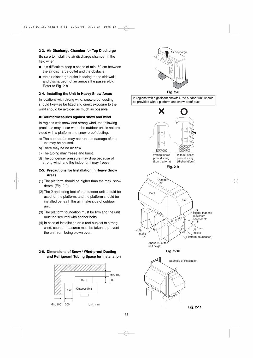
2-3. Air Discharge Chamber for Top Discharge
Be sure to install the air discharge chamber in thefield when:
� it is difficult to keep a space of min. 50 cm betweenthe air discharge outlet and the obstacle.
� the air discharge outlet is facing to the sidewalkand discharged hot air annoys the passers-by.Refer to Fig. 2-8.
2-4. Installing the Unit in Heavy Snow Areas
In locations with strong wind, snow-proof ductingshould likewise be fitted and direct exposure to thewind should be avoided as much as possible.
� Countermeasures against snow and wind
In regions with snow and strong wind, the followingproblems may occur when the outdoor unit is not pro-vided with a platform and snow-proof ducting:
a) The outdoor fan may not run and damage of theunit may be caused.
b) There may be no air flow.
c) The tubing may freeze and burst.
d) The condenser pressure may drop because ofstrong wind, and the indoor unit may freeze.
2-5. Precautions for Installation in Heavy SnowAreas
(1) The platform should be higher than the max. snowdepth. (Fig. 2-9)
(2) The 2 anchoring feet of the outdoor unit should beused for the platform, and the platform should beinstalled beneath the air intake side of outdoorunit.
(3) The platform foundation must be firm and the unitmust be secured with anchor bolts.
(4) In case of installation on a roof subject to strongwind, countermeasures must be taken to preventthe unit from being blown over.
Air discharge
In regions with significant snowfall, the outdoor unit shouldbe provided with a platform and snow-proof duct.
Without snow-proof ducting(Low platform)
Without snow-proof ducting(High platform)
AirIntake
Platform (foundation)
Higher than themaximumsnow depth
Duct
About 1/2 of theunit height
AirIntake
Duct
OutdoorUnit
Duct
Duct
Outdoor Unit
Min. 100
300
Min. 100 300 Unit: mm
Example of Installation
2-6. Dimensions of Snow / Wind-proof Ductingand Refrigerant Tubing Space for Installation
Fig. 2-11
04-393 DC INV Tech p a-44 12/15/04 3:04 PM Page 19
CAFP
20
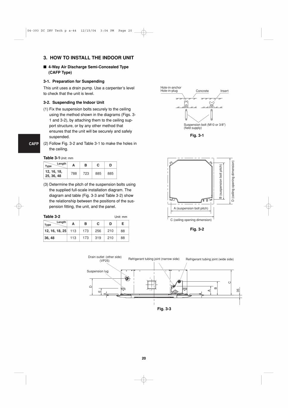
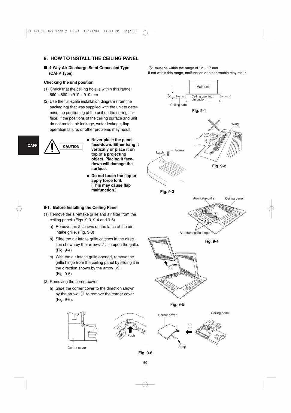
3. HOW TO INSTALL THE INDOOR UNIT
� 4-Way Air Discharge Semi-Concealed Type (CAFP Type)
3-1. Preparation for Suspending
This unit uses a drain pump. Use a carpenter’s levelto check that the unit is level.
3-2. Suspending the Indoor Unit
(1) Fix the suspension bolts securely to the ceilingusing the method shown in the diagrams (Figs. 3-1 and 3-2), by attaching them to the ceiling sup-port structure, or by any other method thatensures that the unit will be securely and safelysuspended.
(2) Follow Fig. 3-2 and Table 3-1 to make the holes inthe ceiling.
Table 3-1Unit: mm
(3) Determine the pitch of the suspension bolts usingthe supplied full-scale installation diagram. Thediagram and table (Fig. 3-3 and Table 3-2) showthe relationship between the positions of the sus-pension fitting, the unit, and the panel.
04-393 DC INV Tech p a-44 12/15/04 3:04 PM Page 20
CAFP
21
Fig. 3-4
Fig. 3-5
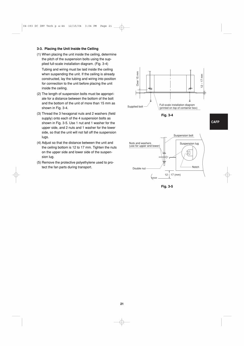
3-3. Placing the Unit Inside the Ceiling
(1) When placing the unit inside the ceiling, determinethe pitch of the suspension bolts using the sup-plied full-scale installation diagram. (Fig. 3-4)
Tubing and wiring must be laid inside the ceilingwhen suspending the unit. If the ceiling is alreadyconstructed, lay the tubing and wiring into positionfor connection to the unit before placing the unitinside the ceiling.
(2) The length of suspension bolts must be appropri-ate for a distance between the bottom of the boltand the bottom of the unit of more than 15 mm asshown in Fig. 3-4.
(3) Thread the 3 hexagonal nuts and 2 washers (fieldsupply) onto each of the 4 suspension bolts asshown in Fig. 3-5. Use 1 nut and 1 washer for theupper side, and 2 nuts and 1 washer for the lowerside, so that the unit will not fall off the suspensionlugs.
(4) Adjust so that the distance between the unit andthe ceiling bottom is 12 to 17 mm. Tighten the nutson the upper side and lower side of the suspen-sion lug.
(5) Remove the protective polyethylene used to pro-tect the fan parts during transport.
Full-scale installation diagram (printed on top of container box)Supplied bolt
Ove
r 15
mm
12 –
17
mm
12 – 17 (mm)
Suspension bolt
Suspension lugNuts and washers (use for upper and lower)
NotchDouble nut
04-393 DC INV Tech p a-44 12/15/04 3:04 PM Page 21
CAFP
22
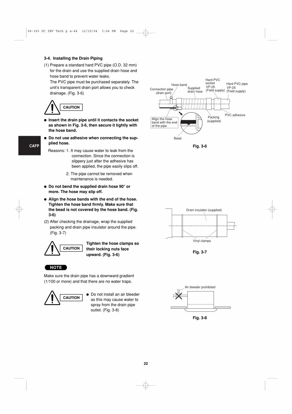
3-4. Installing the Drain Piping
(1) Prepare a standard hard PVC pipe (O.D. 32 mm)for the drain and use the supplied drain hose andhose band to prevent water leaks.The PVC pipe must be purchased separately. Theunit’s transparent drain port allows you to checkdrainage. (Fig. 3-6)
� Insert the drain pipe until it contacts the socketas shown in Fig. 3-6, then secure it tightly withthe hose band.
� Do not use adhesive when connecting the sup-plied hose.
Reasons: 1. It may cause water to leak from theconnection. Since the connection isslippery just after the adhesive hasbeen applied, the pipe easily slips off.
2. The pipe cannot be removed whenmaintenance is needed.
� Do not bend the supplied drain hose 90° ormore. The hose may slip off.
� Align the hose bands with the end of the hose.Tighten the hose band firmly. Make sure thatthe bead is not covered by the hose band. (Fig.3-6)
(2) After checking the drainage, wrap the suppliedpacking and drain pipe insulator around the pipe.(Fig. 3-7)
Make sure the drain pipe has a downward gradient(1/100 or more) and that there are no water traps.
NOTE
CAUTION
CAUTIONTighten the hose clamps sotheir locking nuts faceupward. (Fig. 3-6)
CAUTION� Do not install an air bleeder
as this may cause water tospray from the drain pipeoutlet. (Fig. 3-8)
Fig. 3-6
Fig. 3-7
Fig. 3-8
Bead
Hose bandSupplieddrain hose
Connection pipe(drain port)
Align the hoseband with the endof the pipe
(Field supply) (Field supply)
Packing (supplied)
VP-25VP-25
Hard PVC socket Hard PVC pipe
PVC adhesive
Vinyl clamps
Drain insulator (supplied)
Air bleeder prohibited
04-393 DC INV Tech p a-44 12/15/04 3:04 PM Page 22
CAFP
23
Fig. 3-9
30 cm or less (as short as possible)
64 cm or less
Fig. 3-10
Upward gradient prohibited
Fig. 3-11
Fig. 3-12
Supportpieces
Water (Approx. 1,200 cc)
Over 100 mm
Drain pan outlet
Drainage check
Plastic container for water intake
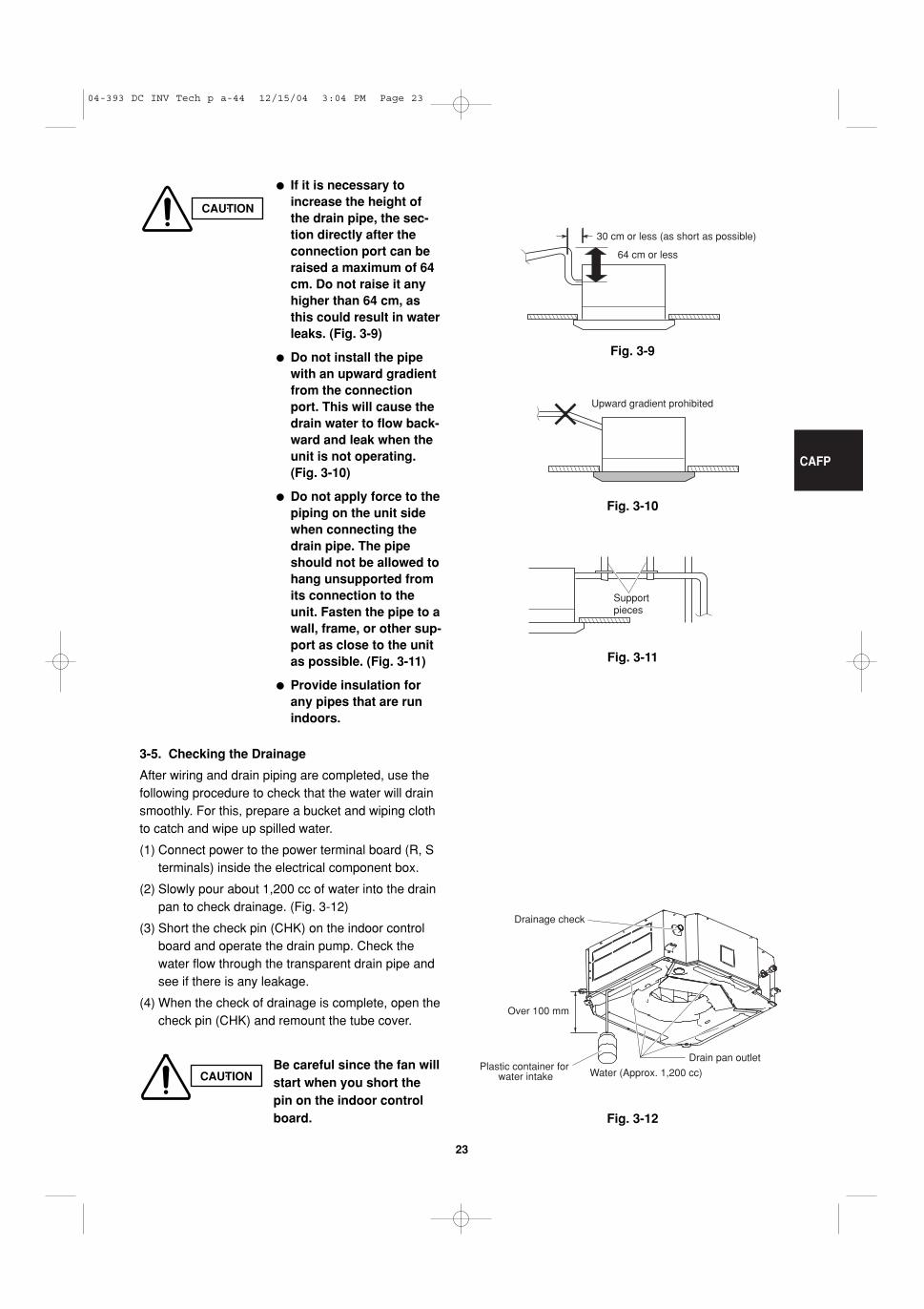
CAUTION
� If it is necessary toincrease the height ofthe drain pipe, the sec-tion directly after theconnection port can beraised a maximum of 64cm. Do not raise it anyhigher than 64 cm, asthis could result in waterleaks. (Fig. 3-9)
� Do not install the pipewith an upward gradientfrom the connectionport. This will cause thedrain water to flow back-ward and leak when theunit is not operating.(Fig. 3-10)
� Do not apply force to thepiping on the unit sidewhen connecting thedrain pipe. The pipeshould not be allowed tohang unsupported fromits connection to theunit. Fasten the pipe to awall, frame, or other sup-port as close to the unitas possible. (Fig. 3-11)
� Provide insulation forany pipes that are runindoors.
3-5. Checking the Drainage
After wiring and drain piping are completed, use thefollowing procedure to check that the water will drainsmoothly. For this, prepare a bucket and wiping clothto catch and wipe up spilled water.
(1) Connect power to the power terminal board (R, Sterminals) inside the electrical component box.
(2) Slowly pour about 1,200 cc of water into the drainpan to check drainage. (Fig. 3-12)
(3) Short the check pin (CHK) on the indoor controlboard and operate the drain pump. Check thewater flow through the transparent drain pipe andsee if there is any leakage.
(4) When the check of drainage is complete, open thecheck pin (CHK) and remount the tube cover.
CAUTIONBe careful since the fan willstart when you short thepin on the indoor controlboard.
04-393 DC INV Tech p a-44 12/15/04 3:04 PM Page 23
MAFP
24
� Wall-Mounted Type (MAFP Type)
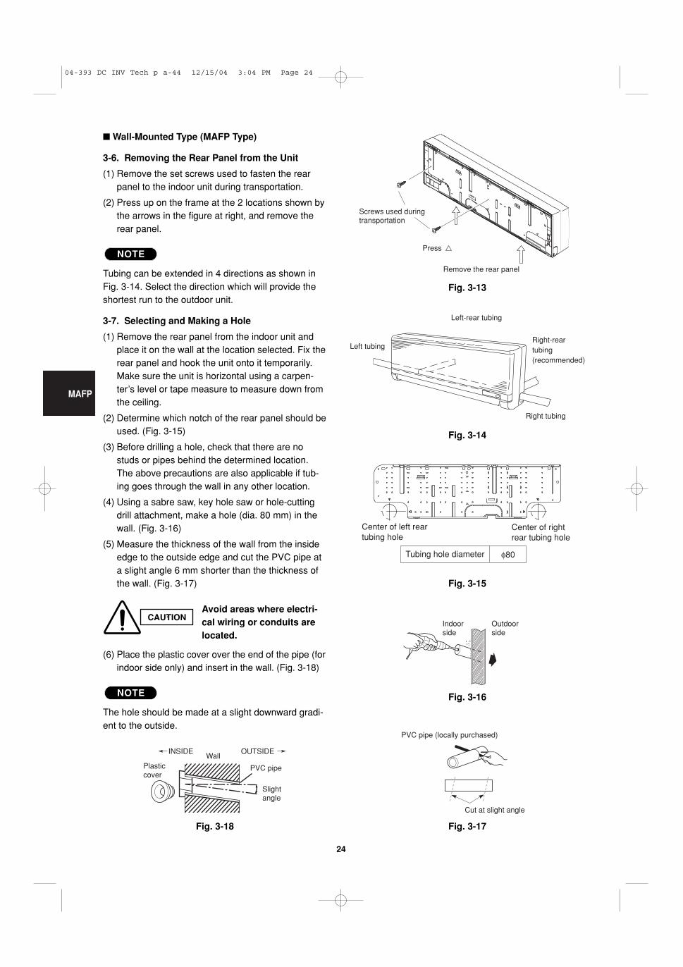
3-6. Removing the Rear Panel from the Unit
(1) Remove the set screws used to fasten the rearpanel to the indoor unit during transportation.
(2) Press up on the frame at the 2 locations shown bythe arrows in the figure at right, and remove therear panel.
Tubing can be extended in 4 directions as shown inFig. 3-14. Select the direction which will provide theshortest run to the outdoor unit.
3-7. Selecting and Making a Hole
(1) Remove the rear panel from the indoor unit andplace it on the wall at the location selected. Fix therear panel and hook the unit onto it temporarily.Make sure the unit is horizontal using a carpen-ter’s level or tape measure to measure down fromthe ceiling.
(2) Determine which notch of the rear panel should beused. (Fig. 3-15)
(3) Before drilling a hole, check that there are nostuds or pipes behind the determined location.The above precautions are also applicable if tub-ing goes through the wall in any other location.
(4) Using a sabre saw, key hole saw or hole-cuttingdrill attachment, make a hole (dia. 80 mm) in thewall. (Fig. 3-16)
(5) Measure the thickness of the wall from the insideedge to the outside edge and cut the PVC pipe ata slight angle 6 mm shorter than the thickness ofthe wall. (Fig. 3-17)
(6) Place the plastic cover over the end of the pipe (forindoor side only) and insert in the wall. (Fig. 3-18)
The hole should be made at a slight downward gradi-ent to the outside.
NOTE
NOTE
Fig. 3-13
Fig. 3-14
Fig. 3-15
Fig. 3-16
Fig. 3-17Fig. 3-18
CAUTIONAvoid areas where electri-cal wiring or conduits arelocated.
Plastic cover
INSIDEWall
Slightangle
PVC pipe
OUTSIDE
Cut at slight angle
PVC pipe (locally purchased)
Indoorside
Outdoorside
Center of left rear tubing hole
Center of right rear tubing hole
Tubing hole diameter φ80
Left tubing Right-reartubing(recommended)
Right tubing
Left-rear tubing
Remove the rear panel
Press
Screws used during transportation
04-393 DC INV Tech p a-44 12/15/04 3:04 PM Page 24
MAFP
25
Fig. 3-19
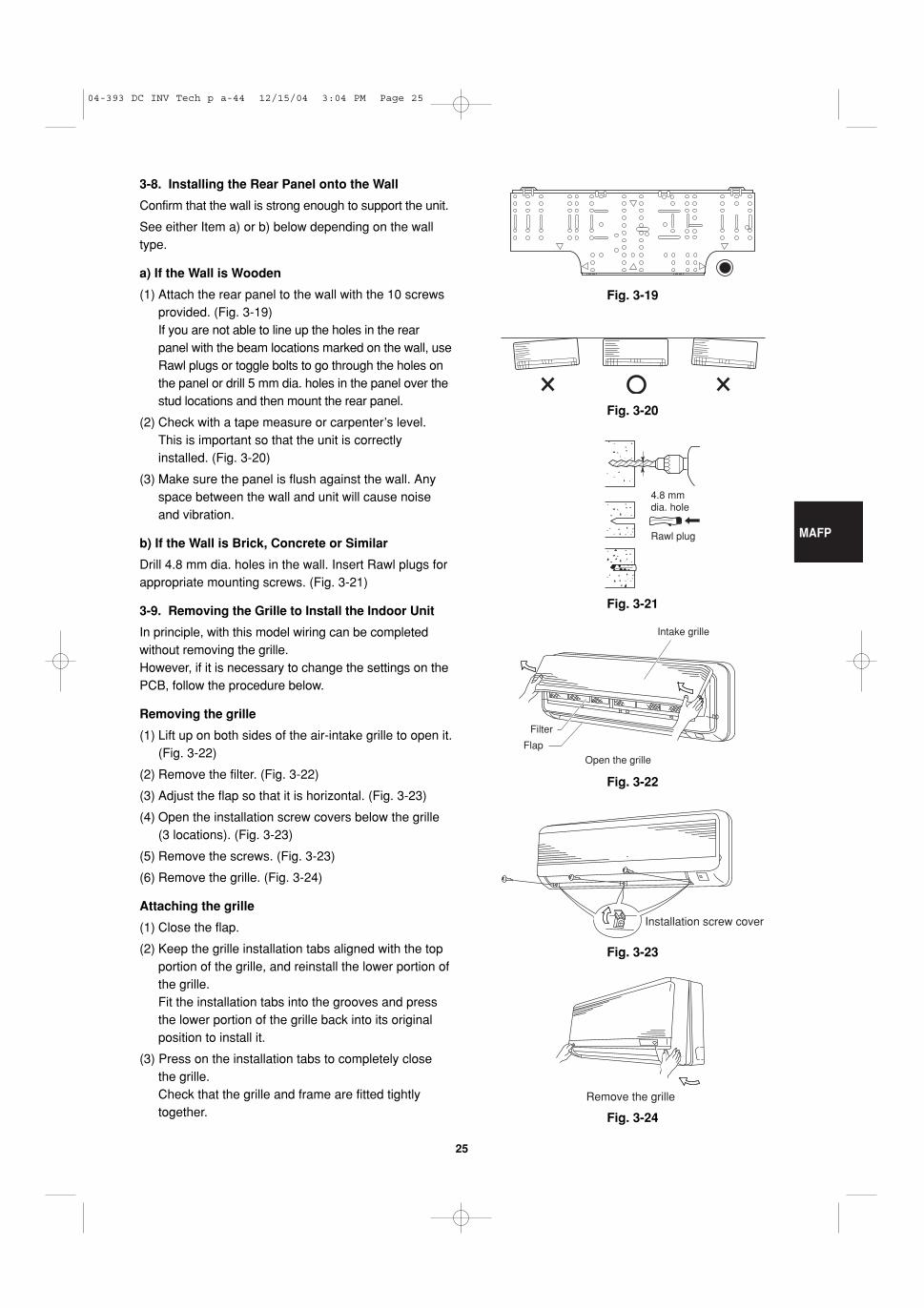
3-8. Installing the Rear Panel onto the Wall
Confirm that the wall is strong enough to support the unit.
See either Item a) or b) below depending on the walltype.
a) If the Wall is Wooden
(1) Attach the rear panel to the wall with the 10 screwsprovided. (Fig. 3-19)If you are not able to line up the holes in the rearpanel with the beam locations marked on the wall, useRawl plugs or toggle bolts to go through the holes onthe panel or drill 5 mm dia. holes in the panel over thestud locations and then mount the rear panel.
(2) Check with a tape measure or carpenter’s level.This is important so that the unit is correctlyinstalled. (Fig. 3-20)
(3) Make sure the panel is flush against the wall. Anyspace between the wall and unit will cause noiseand vibration.
b) If the Wall is Brick, Concrete or Similar
Drill 4.8 mm dia. holes in the wall. Insert Rawl plugs forappropriate mounting screws. (Fig. 3-21)
3-9. Removing the Grille to Install the Indoor Unit
In principle, with this model wiring can be completedwithout removing the grille. However, if it is necessary to change the settings on thePCB, follow the procedure below.
Removing the grille
(1) Lift up on both sides of the air-intake grille to open it.(Fig. 3-22)
(2) Remove the filter. (Fig. 3-22)
(3) Adjust the flap so that it is horizontal. (Fig. 3-23)
(4) Open the installation screw covers below the grille(3 locations). (Fig. 3-23)
(5) Remove the screws. (Fig. 3-23)
(6) Remove the grille. (Fig. 3-24)
Attaching the grille
(1) Close the flap.
(2) Keep the grille installation tabs aligned with the topportion of the grille, and reinstall the lower portion ofthe grille. Fit the installation tabs into the grooves and pressthe lower portion of the grille back into its originalposition to install it.
(3) Press on the installation tabs to completely closethe grille. Check that the grille and frame are fitted tightlytogether.
Fig. 3-20
Fig. 3-21
Fig. 3-22
Fig. 3-23
Fig. 3-24
4.8 mmdia. hole
Rawl plug
Intake grille
Filter
Flap
Open the grille
Installation screw cover
Remove the grille
04-393 DC INV Tech p a-44 12/15/04 3:04 PM Page 25
MAFP
26
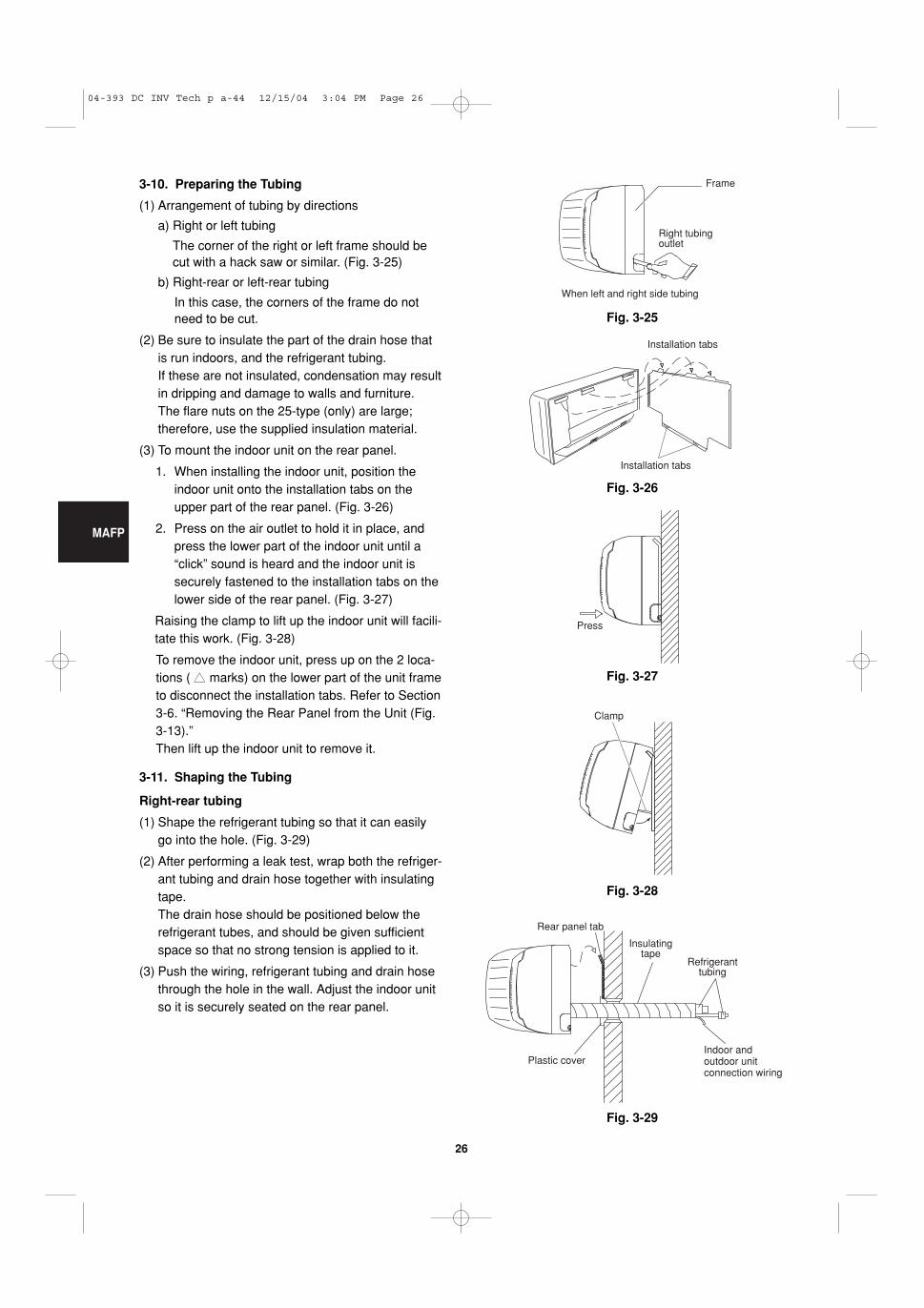
3-10. Preparing the Tubing
(1) Arrangement of tubing by directions
a) Right or left tubing
The corner of the right or left frame should becut with a hack saw or similar. (Fig. 3-25)
b) Right-rear or left-rear tubing
In this case, the corners of the frame do notneed to be cut.
(2) Be sure to insulate the part of the drain hose thatis run indoors, and the refrigerant tubing. If these are not insulated, condensation may resultin dripping and damage to walls and furniture. The flare nuts on the 25-type (only) are large;therefore, use the supplied insulation material.
(3) To mount the indoor unit on the rear panel.
1. When installing the indoor unit, position theindoor unit onto the installation tabs on theupper part of the rear panel. (Fig. 3-26)
2. Press on the air outlet to hold it in place, andpress the lower part of the indoor unit until a“click” sound is heard and the indoor unit issecurely fastened to the installation tabs on thelower side of the rear panel. (Fig. 3-27)
Raising the clamp to lift up the indoor unit will facili-tate this work. (Fig. 3-28)
To remove the indoor unit, press up on the 2 loca-tions ( �� marks) on the lower part of the unit frameto disconnect the installation tabs. Refer to Section3-6. “Removing the Rear Panel from the Unit (Fig.3-13).”Then lift up the indoor unit to remove it.
3-11. Shaping the Tubing
Right-rear tubing
(1) Shape the refrigerant tubing so that it can easilygo into the hole. (Fig. 3-29)
(2) After performing a leak test, wrap both the refriger-ant tubing and drain hose together with insulatingtape. The drain hose should be positioned below therefrigerant tubes, and should be given sufficientspace so that no strong tension is applied to it.
(3) Push the wiring, refrigerant tubing and drain hosethrough the hole in the wall. Adjust the indoor unitso it is securely seated on the rear panel.
Fig. 3-25
Frame
Right tubingoutlet
When left and right side tubing
Fig. 3-26
Installation tabs
Installation tabs
Fig. 3-27
Press
Fig. 3-28
Clamp
Fig. 3-29
Insulatingtape
Refrigeranttubing
Rear panel tab
Plastic coverIndoor and outdoor unit connection wiring
04-393 DC INV Tech p a-44 12/15/04 3:04 PM Page 26
MAFP
27
Fig. 3-32
Fig. 3-30
Insulation
Fig. 3-31
Insulating tape Rear panel
Inter-unit wiring
Refrigerant tubing
Drain hose
Indoor unit
Slant
Refrigeranttubing
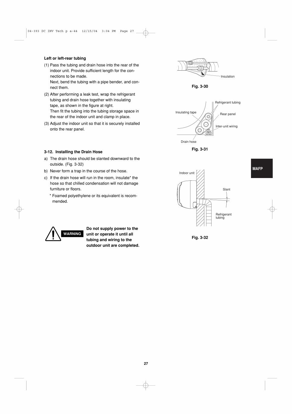
3-12. Installing the Drain Hose
a) The drain hose should be slanted downward to theoutside. (Fig. 3-32)
b) Never form a trap in the course of the hose.
c) If the drain hose will run in the room, insulate* thehose so that chilled condensation will not damagefurniture or floors.
* Foamed polyethylene or its equivalent is recom-mended.
WARNINGDo not supply power to theunit or operate it until alltubing and wiring to theoutdoor unit are completed.
Left or left-rear tubing
(1) Pass the tubing and drain hose into the rear of theindoor unit. Provide sufficient length for the con-nections to be made.Next, bend the tubing with a pipe bender, and con-nect them.
(2) After performing a leak test, wrap the refrigeranttubing and drain hose together with insulatingtape, as shown in the figure at right. Then fit the tubing into the tubing storage space inthe rear of the indoor unit and clamp in place.
(3) Adjust the indoor unit so that it is securely installedonto the rear panel.
04-393 DC INV Tech p a-44 12/15/04 3:04 PM Page 27
SPAFP
28
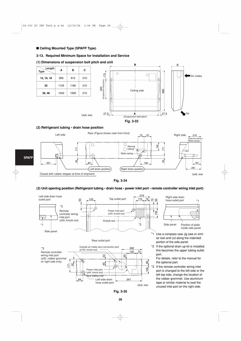
� Ceiling Mounted Type (SPAFP Type)
3-13. Required Minimum Space for Installation and Service
(1) Dimensions of suspension bolt pitch and unit
12, 16, 18
25
36, 48
855
1125
1540
910
1180
1595
210
210
210
A B CLength
Type
B C
A
170
320
680
27.5 27.5
Ceiling side
(Suspension bolt pitch)
(Sus
pens
ion
bolt
pitc
h)
Air intake
Air
(2) Refrigerant tubing • drain hose position
(3) Unit opening position (Refrigerant tubing • drain hose • power inlet port • remote controller wiring inlet port)
251 84 146 161
75 97 216
39 39
171 10
5
171
251
Wide tubing
Narrow tubing
Right sideLeft sideRear (Figure shows view from front)
Remote controller wiring inlet port(φ30, rubber grommet on right side only)
Outside air intake duct connection port(φ100, knock-out)
Rear outlet port
*3
*1
*1
*2
*3
Fig. 3-33
Fig. 3-35
Fig. 3-34
*1 Use a compass saw, jig saw or simi-lar tool and cut along the indentedportion of the side panel.
*2 If the optional drain up kit is installed,this becomes the upper tubing outletport. For details, refer to the manual forthe optional part.
*3 If the remote controller wiring inletport is changed to the left side or theleft top side, change the location ofthe rubber grommet. Use aluminumtape or similar material to seal theunused inlet port on the right side.
Unit: mm
Unit: mm
Unit: mm
04-393 DC INV Tech p a-44 12/15/04 3:04 PM Page 28
SPAFP
29
(4) Wall and ceiling side opening position
90
145
135 125
15590
*
Figure shows view from front Figure shows view from top
φ100 wall side opening (for left-side drain hose)
φ100 wall side openingφ100 ceiling opening
φ100 ceiling opening
WallCeiling
Full-scale installation diagram
Wall
Ceiling
Fig. 3-37
Fig. 3-36
Fig. 3-38
3-14. Suspending the Indoor Unit
(1) Place the full-scale diagram (supplied) on the ceil-ing at the spot where you want to install the indoorunit. Use a pencil to mark the drill holes. (Fig. 3-37).
Since the diagram is made of paper, it may shrink orstretch slightly because of high temperature or humid-ity. For this reason, before drilling the holes maintainthe correct dimensions between the markings.
(2) Drill holes at the 4 points indicated on the full-scale diagram.
(3) Depending on the ceiling type:
a) Insert suspension bolts as shown in Fig. 3-38.
or
b) Use existing ceiling supports or construct a suit-able support as shown in Fig. 3-39.
NOTE
WARNINGIt is important that you useextreme care in supportingthe indoor unit from the ceil-ing. Ensure that the ceilingis strong enough to supportthe weight of the unit. Beforehanging the ceiling unit, testthe strength of eachattached suspension bolt.
(4) Screw in the suspension bolts, allowing them toprotrude from the ceiling as shown in Figs. 3-38and 3-39. The distance of each exposed bolt mustbe of equal length within 50 mm. (Fig. 3-40)
Hole-in-anchorHole-in-plug Concrete Insert
Suspension bolt (M10 or 3/8")(field supply)
Fig. 3-39
Fig. 3-40
Ceiling tiles
Ceiling support
A
A
unitCeilingsurface
Fixture
With
in50
mm
* If the optional drain up kit is installed, create a φ100 hole along the dotted line (part marked with * in figure).
Unit: mm
04-393 DC INV Tech p a-44 12/15/04 3:04 PM Page 29
SPAFP
30
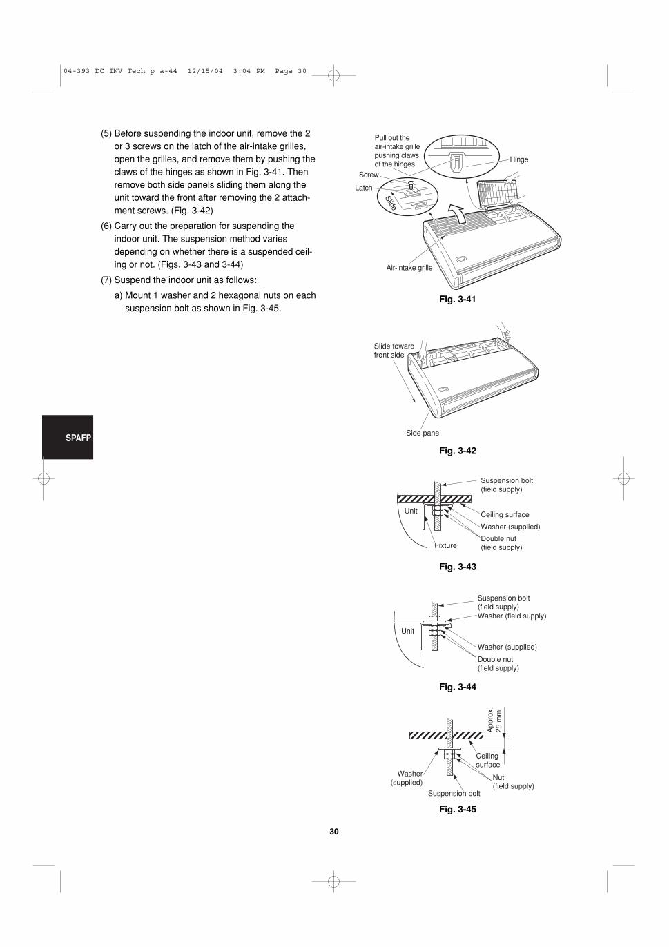
Fig. 3-41
Slide
Hinge
Air-intake grille
Pull out theair-intake grillepushing clawsof the hinges
Screw
Latch
Fig. 3-42
Slide towardfront side
Side panel
Fig. 3-43
Unit
Suspension bolt(field supply)
Ceiling surface
Washer (supplied)
Double nut(field supply)Fixture
Fig. 3-44
Unit
Suspension bolt(field supply)
Washer (supplied)
Washer (field supply)
Double nut(field supply)
Fig. 3-45
Ceilingsurface
App
rox.
25
mm
Suspension bolt
Washer(supplied)
Nut(field supply)
(5) Before suspending the indoor unit, remove the 2or 3 screws on the latch of the air-intake grilles,open the grilles, and remove them by pushing theclaws of the hinges as shown in Fig. 3-41. Thenremove both side panels sliding them along theunit toward the front after removing the 2 attach-ment screws. (Fig. 3-42)
(6) Carry out the preparation for suspending theindoor unit. The suspension method variesdepending on whether there is a suspended ceil-ing or not. (Figs. 3-43 and 3-44)
(7) Suspend the indoor unit as follows:
a) Mount 1 washer and 2 hexagonal nuts on eachsuspension bolt as shown in Fig. 3-45.
04-393 DC INV Tech p a-44 12/15/04 3:04 PM Page 30
SPAFP
31
Fig. 3-46
Fig. 3-47
Fig. 3-48
Indoorside
Outdoorside
Fig. 3-49
Cut at slight angle
PVC pipe (locally purchased)INSIDE
Wall
Slightangle
PVC pipe
OUTSIDE
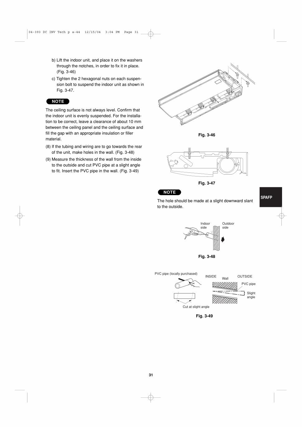
b) Lift the indoor unit, and place it on the washersthrough the notches, in order to fix it in place.(Fig. 3-46)
c) Tighten the 2 hexagonal nuts on each suspen-sion bolt to suspend the indoor unit as shown inFig. 3-47.
The ceiling surface is not always level. Confirm thatthe indoor unit is evenly suspended. For the installa-tion to be correct, leave a clearance of about 10 mmbetween the ceiling panel and the ceiling surface andfill the gap with an appropriate insulation or fillermaterial.
(8) If the tubing and wiring are to go towards the rearof the unit, make holes in the wall. (Fig. 3-48)
(9) Measure the thickness of the wall from the insideto the outside and cut PVC pipe at a slight angleto fit. Insert the PVC pipe in the wall. (Fig. 3-49)
NOTE
The hole should be made at a slight downward slantto the outside.
NOTE
04-393 DC INV Tech p a-44 12/15/04 3:04 PM Page 31
SPAFP
32
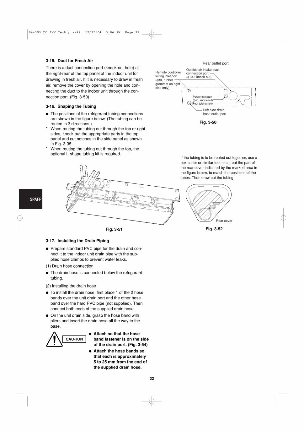
3-15. Duct for Fresh Air
There is a duct connection port (knock-out hole) atthe right-rear of the top panel of the indoor unit fordrawing in fresh air. If it is necessary to draw in freshair, remove the cover by opening the hole and con-necting the duct to the indoor unit through the con-nection port. (Fig. 3-50)
3-16. Shaping the Tubing
� The positions of the refrigerant tubing connectionsare shown in the figure below. (The tubing can berouted in 3 directions.)
* When routing the tubing out through the top or rightsides, knock out the appropriate parts in the toppanel and cut notches in the side panel as shownin Fig. 3-35.
* When routing the tubing out through the top, theoptional L-shape tubing kit is required.
3-17. Installing the Drain Piping
� Prepare standard PVC pipe for the drain and con-nect it to the indoor unit drain pipe with the sup-plied hose clamps to prevent water leaks.
(1) Drain hose connection
� The drain hose is connected below the refrigeranttubing.
(2) Installing the drain hose
� To install the drain hose, first place 1 of the 2 hosebands over the unit drain port and the other hoseband over the hard PVC pipe (not supplied). Thenconnect both ends of the supplied drain hose.
� On the unit drain side, grasp the hose band withpliers and insert the drain hose all the way to thebase.
Power inlet port(φ40, knock-out)
Left-side drain hose outlet port
Rear tubing hole
Remote controller wiring inlet port(φ30, rubber grommet on right side only)
Outside air intake duct connection port(φ100, knock-out)
Rear outlet port
Fig. 3-50
Rear cover
CAUTION� Attach so that the hose
band fastener is on the sideof the drain port. (Fig. 3-54)
� Attach the hose bands sothat each is approximately 5 to 25 mm from the end ofthe supplied drain hose.
If the tubing is to be routed out together, use abox cutter or similar tool to cut out the part ofthe rear cover indicated by the marked area inthe figure below, to match the positions of thetubes. Then draw out the tubing.
Fig. 3-51 Fig. 3-52
04-393 DC INV Tech p a-44 12/15/04 3:04 PM Page 32
SPAFP
33
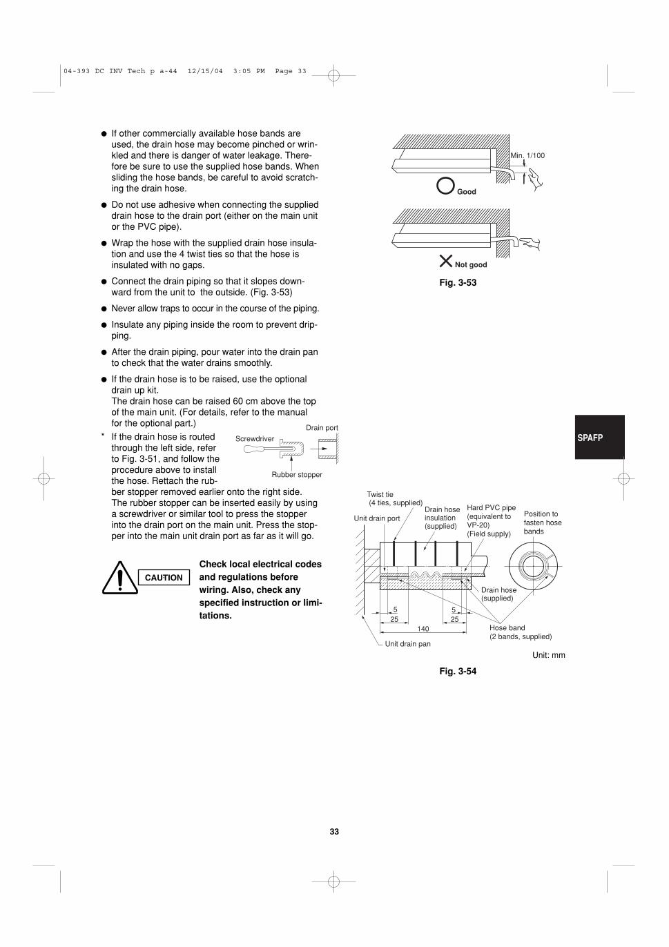
14025 25
55
Position to fasten hose bands
Drain hose(supplied)
Hose band (2 bands, supplied)
Unit drain pan
Unit drain port Drain hose insulation (supplied)
Twist tie (4 ties, supplied)
Hard PVC pipe (equivalent to VP-20)(Field supply)
Fig. 3-54
Good
Min. 1/100
Not good
Fig. 3-53
� If other commercially available hose bands areused, the drain hose may become pinched or wrin-kled and there is danger of water leakage. There-fore be sure to use the supplied hose bands. Whensliding the hose bands, be careful to avoid scratch-ing the drain hose.
� Do not use adhesive when connecting the supplieddrain hose to the drain port (either on the main unitor the PVC pipe).
� Wrap the hose with the supplied drain hose insula-tion and use the 4 twist ties so that the hose isinsulated with no gaps.
� Connect the drain piping so that it slopes down-ward from the unit to the outside. (Fig. 3-53)
� Never allow traps to occur in the course of the piping.
� Insulate any piping inside the room to prevent drip-ping.
� After the drain piping, pour water into the drain panto check that the water drains smoothly.
� If the drain hose is to be raised, use the optionaldrain up kit. The drain hose can be raised 60 cm above the topof the main unit. (For details, refer to the manualfor the optional part.)
* If the drain hose is routedthrough the left side, referto Fig. 3-51, and follow theprocedure above to installthe hose. Rettach the rub-ber stopper removed earlier onto the right side. The rubber stopper can be inserted easily by usinga screwdriver or similar tool to press the stopperinto the drain port on the main unit. Press the stop-per into the main unit drain port as far as it will go.
Screwdriver
Rubber stopper
Drain port
CAUTION
Check local electrical codesand regulations beforewiring. Also, check anyspecified instruction or limi-tations.
Unit: mm
04-393 DC INV Tech p a-44 12/15/04 3:05 PM Page 33
SPAFP
34
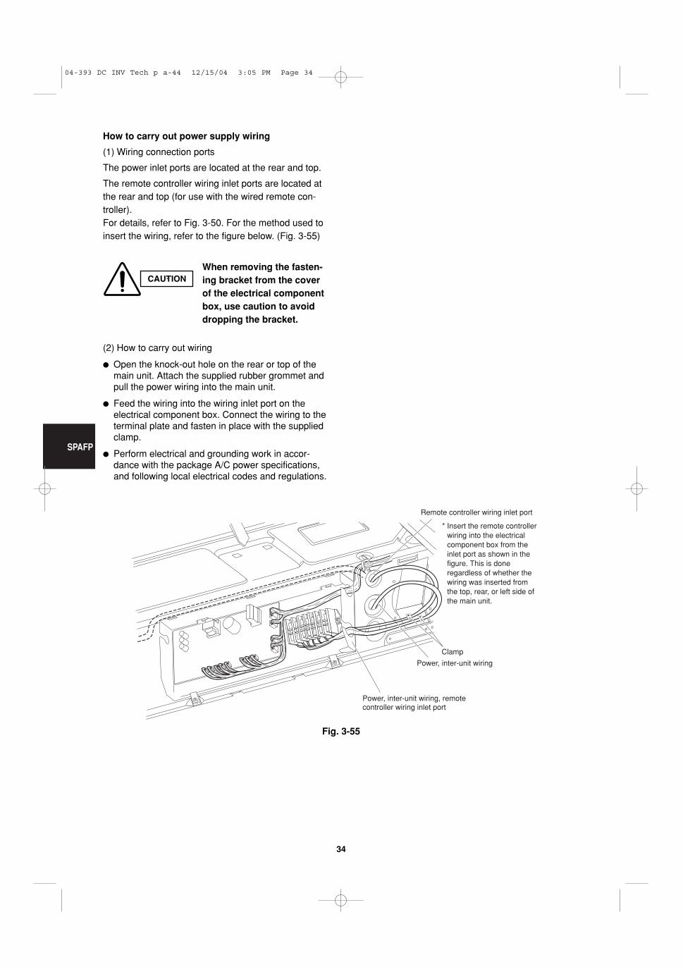
* Insert the remote controller wiring into the electrical component box from the inlet port as shown in the figure. This is done regardless of whether the wiring was inserted from the top, rear, or left side of the main unit.
Remote controller wiring inlet port
Power, inter-unit wiring
Power, inter-unit wiring, remote controller wiring inlet port
Clamp
How to carry out power supply wiring
(1) Wiring connection ports
The power inlet ports are located at the rear and top.
The remote controller wiring inlet ports are located atthe rear and top (for use with the wired remote con-troller). For details, refer to Fig. 3-50. For the method used toinsert the wiring, refer to the figure below. (Fig. 3-55)
(2) How to carry out wiring
� Open the knock-out hole on the rear or top of themain unit. Attach the supplied rubber grommet andpull the power wiring into the main unit.
� Feed the wiring into the wiring inlet port on theelectrical component box. Connect the wiring to theterminal plate and fasten in place with the suppliedclamp.
� Perform electrical and grounding work in accor-dance with the package A/C power specifications,and following local electrical codes and regulations.
CAUTIONWhen removing the fasten-ing bracket from the coverof the electrical componentbox, use caution to avoiddropping the bracket.
Fig. 3-55
04-393 DC INV Tech p a-44 12/15/04 3:05 PM Page 34
DSAFP
35
Fig. 3-56
Fig. 3-57
Indoor unitInspectionaccess450 450
Air outlet duct flange
min. 250
min
. 400 min. 650
580
A (Suspension bolt pitch) Electricalcomponent box
Refrigeranttubing
min
. 25
0
� Concealed-Duct Type (DSAFP Type)
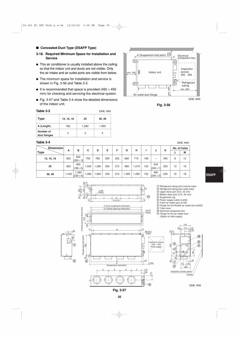
3-18. Required Minimum Space for Installation andService
� This air conditioner is usually installed above the ceilingso that the indoor unit and ducts are not visible. Onlythe air intake and air outlet ports are visible from below.
� The minimum space for installation and service isshown in Fig. 3-56 and Table 3-3.
� It is recommended that space is provided (450 × 450mm) for checking and servicing the electrical system.
� Fig. 3-57 and Table 3-4 show the detailed dimensionsof the indoor unit.
Table 3-3
Table 3-4
Type
A (Length)
Number ofduct flanges
36, 48
1,560
4
25
1,080
3
12, 16, 18
780
2
DimensionType
12, 16, 18
25
36, 48
E F G H I J K
662600
700 780 290 262 680 715 180 – 340 8 12(200 × 3)
962900
1,000 1,080 290 272 980 1,015 130245
250 12 16(180 × 5) (245 × 1)
1,4421,380
1,480 1,560 335 310 1,460 1,495 130490
240 16 18(230 × 6) (245 × 2)
No. of holes
L MC DBA
Refrigerant tubing joint (narrow tube)Refrigerant tubing joint (wide tube)Upper drain port (O.D. 32 mm)Bottom drain port (O.D. 26 mm)Suspension lugPower supply outlet (2-ø30)Fresh air intake port (ø150)Flange for the flexible air outlet duct (ø200)Tube cover Electrical component boxFlange for the air intake duct(Option or field supply)
9
10
9
10
11
11
(Suspension bolt pitch)
(Sus
pens
ion
bolt
pitc
h)
M-ø3.3(Hole)
4-ø12(Hole)
(Hole)
A (O.D.)
L-ø6
I
10 10
105555
200
10 IJJ K
B
CD (150)
40
E E E F 7565
285
70 130
25 210
310
25175
35
903131
H (Duct suspension bolt pitch)G (Ceiling opening dimension)
25
100
185
580
25
115
190
85
2570
30 160
630
25 10
8827
5(C
eilin
g op
enin
g di
men
sion
)26
0(O
.D.)
1919
Inspection access(450 × 450)
(Field supply)
Inspection access panel
Ceiling
Unit: mm
Unit: mm
Unit: mm
Unit: mm
04-393 DC INV Tech p a-44 12/15/04 3:05 PM Page 35
DSAFP
36
Fig. 3-58
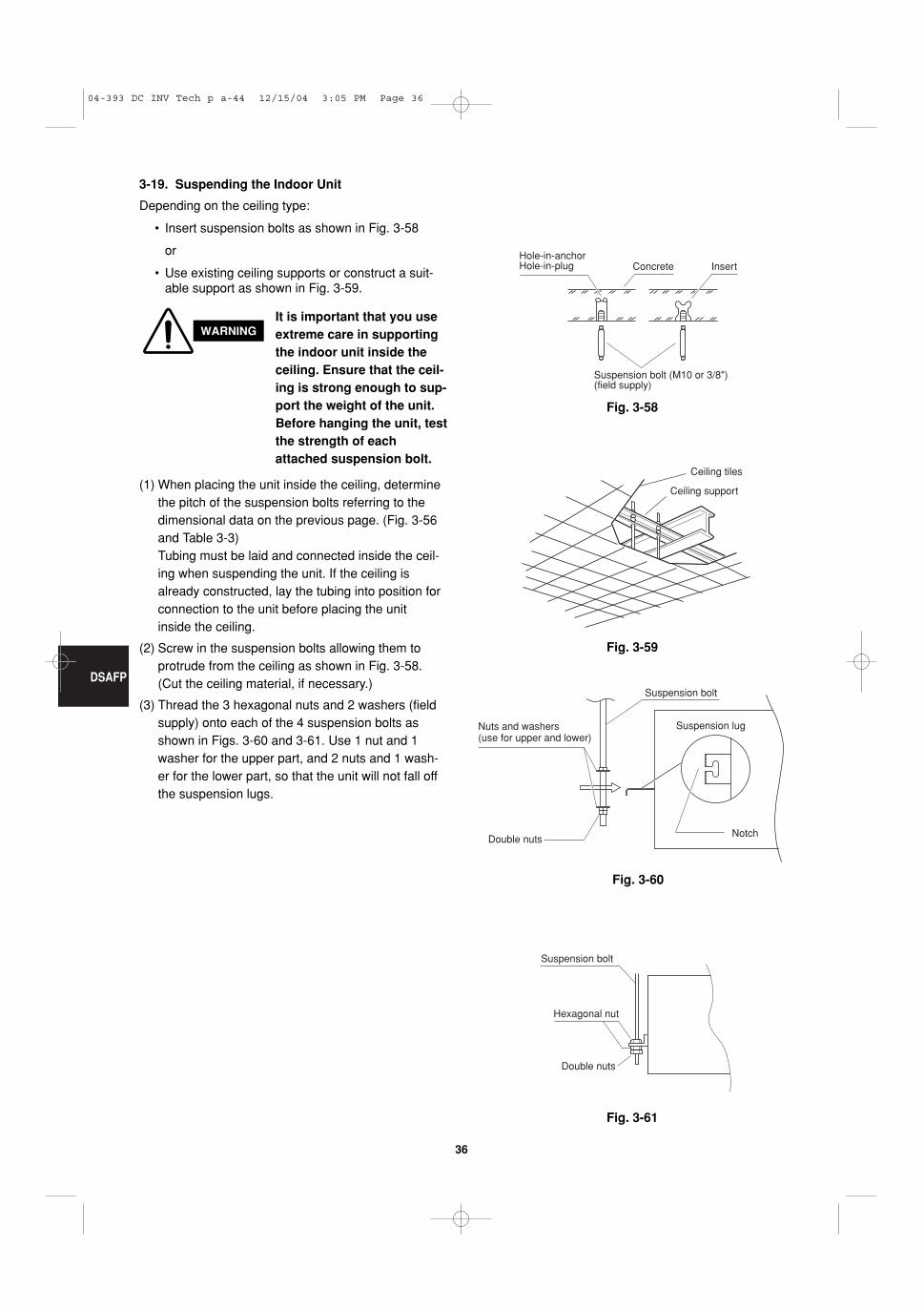
3-19. Suspending the Indoor Unit
Depending on the ceiling type:
• Insert suspension bolts as shown in Fig. 3-58
or
• Use existing ceiling supports or construct a suit-able support as shown in Fig. 3-59.
Hole-in-anchorHole-in-plug Concrete Insert
Suspension bolt (M10 or 3/8")(field supply)
Fig. 3-59
Fig. 3-60
Fig. 3-61
Ceiling tiles
Ceiling support
Suspension bolt
Suspension lugNuts and washers (use for upper and lower)
Double nutsNotch
Suspension bolt
Hexagonal nut
Double nuts
WARNINGIt is important that you useextreme care in supportingthe indoor unit inside theceiling. Ensure that the ceil-ing is strong enough to sup-port the weight of the unit.Before hanging the unit, testthe strength of eachattached suspension bolt.
(1) When placing the unit inside the ceiling, determinethe pitch of the suspension bolts referring to thedimensional data on the previous page. (Fig. 3-56and Table 3-3) Tubing must be laid and connected inside the ceil-ing when suspending the unit. If the ceiling isalready constructed, lay the tubing into position forconnection to the unit before placing the unitinside the ceiling.
(2) Screw in the suspension bolts allowing them toprotrude from the ceiling as shown in Fig. 3-58.(Cut the ceiling material, if necessary.)
(3) Thread the 3 hexagonal nuts and 2 washers (fieldsupply) onto each of the 4 suspension bolts asshown in Figs. 3-60 and 3-61. Use 1 nut and 1washer for the upper part, and 2 nuts and 1 wash-er for the lower part, so that the unit will not fall offthe suspension lugs.
04-393 DC INV Tech p a-44 12/15/04 3:05 PM Page 36
DSAFP
37
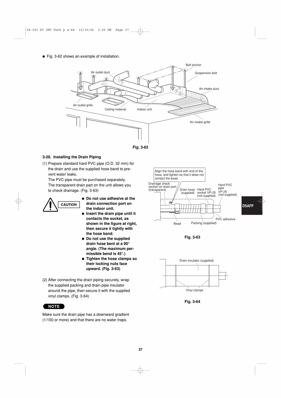
� Fig. 3-62 shows an example of installation.
Air outlet duct
Air-outlet grilleCeiling material Indoor unit
Bolt anchor
Suspension bolt
Air-intake duct
Air-intake grille
Fig. 3-62
Fig. 3-63
Fig. 3-64
Drain hose (supplied)
(not supplied) (not supplied)
Packing (supplied)
VP-25
Align the hose band with end of the hose, and tighten so that it does not contact the bead.
Drainage check section on drain port (transparent) Hard PVC
socket VP-25
Hard PVC pipe
PVC adhesiveBead
Vinyl clamps
Drain insulator (supplied)
3-20. Installing the Drain Piping
(1) Prepare standard hard PVC pipe (O.D. 32 mm) forthe drain and use the supplied hose band to pre-vent water leaks.The PVC pipe must be purchased separately.The transparent drain part on the unit allows youto check drainage. (Fig. 3-63)
CAUTION
� Do not use adhesive at thedrain connection port onthe indoor unit.
� Insert the drain pipe until itcontacts the socket, asshown in the figure at right,then secure it tightly withthe hose band.
� Do not use the supplieddrain hose bent at a 90°angle. (The maximum per-missible bend is 45°.)
(2) After connecting the drain piping securely, wrapthe supplied packing and drain pipe insulatoraround the pipe, then secure it with the suppliedvinyl clamps. (Fig. 3-64)
Make sure the drain pipe has a downward gradient(1/100 or more) and that there are no water traps.
NOTE
04-393 DC INV Tech p a-44 12/15/04 3:05 PM Page 37
DSAFP
38
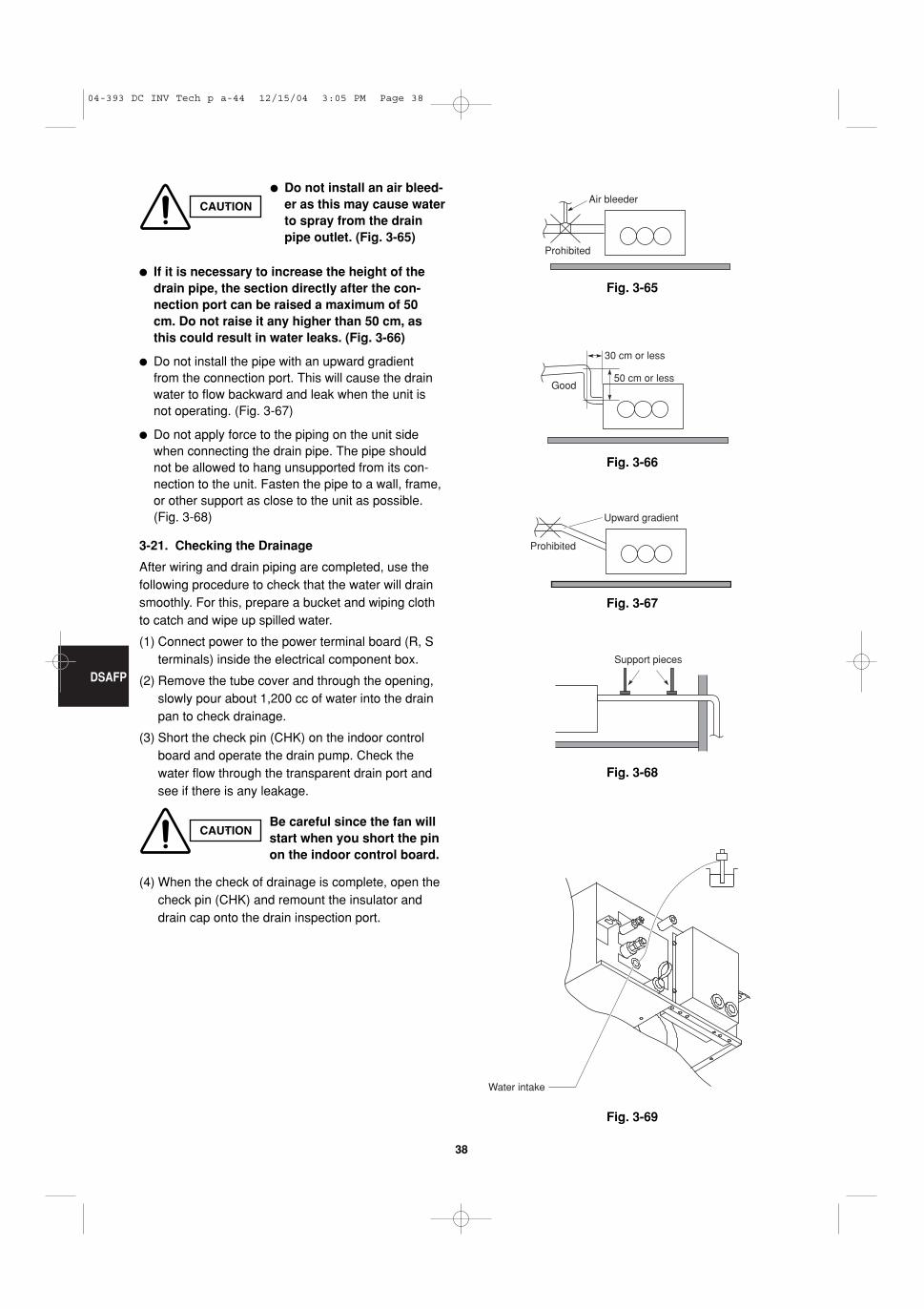
Fig. 3-65
Fig. 3-66
Fig. 3-67
Fig. 3-68
Fig. 3-69
Air bleeder
Prohibited
Good
30 cm or less
50 cm or less
Prohibited
Upward gradient
Support pieces
Water intake
� If it is necessary to increase the height of thedrain pipe, the section directly after the con-nection port can be raised a maximum of 50cm. Do not raise it any higher than 50 cm, asthis could result in water leaks. (Fig. 3-66)
� Do not install the pipe with an upward gradientfrom the connection port. This will cause the drainwater to flow backward and leak when the unit isnot operating. (Fig. 3-67)
� Do not apply force to the piping on the unit sidewhen connecting the drain pipe. The pipe shouldnot be allowed to hang unsupported from its con-nection to the unit. Fasten the pipe to a wall, frame,or other support as close to the unit as possible.(Fig. 3-68)
3-21. Checking the Drainage
After wiring and drain piping are completed, use thefollowing procedure to check that the water will drainsmoothly. For this, prepare a bucket and wiping clothto catch and wipe up spilled water.
(1) Connect power to the power terminal board (R, Sterminals) inside the electrical component box.
(2) Remove the tube cover and through the opening,slowly pour about 1,200 cc of water into the drainpan to check drainage.
(3) Short the check pin (CHK) on the indoor controlboard and operate the drain pump. Check thewater flow through the transparent drain port andsee if there is any leakage.
(4) When the check of drainage is complete, open thecheck pin (CHK) and remount the insulator anddrain cap onto the drain inspection port.
CAUTION
� Do not install an air bleed-er as this may cause waterto spray from the drainpipe outlet. (Fig. 3-65)
CAUTIONBe careful since the fan willstart when you short the pinon the indoor control board.
04-393 DC INV Tech p a-44 12/15/04 3:05 PM Page 38
DSAFP
39
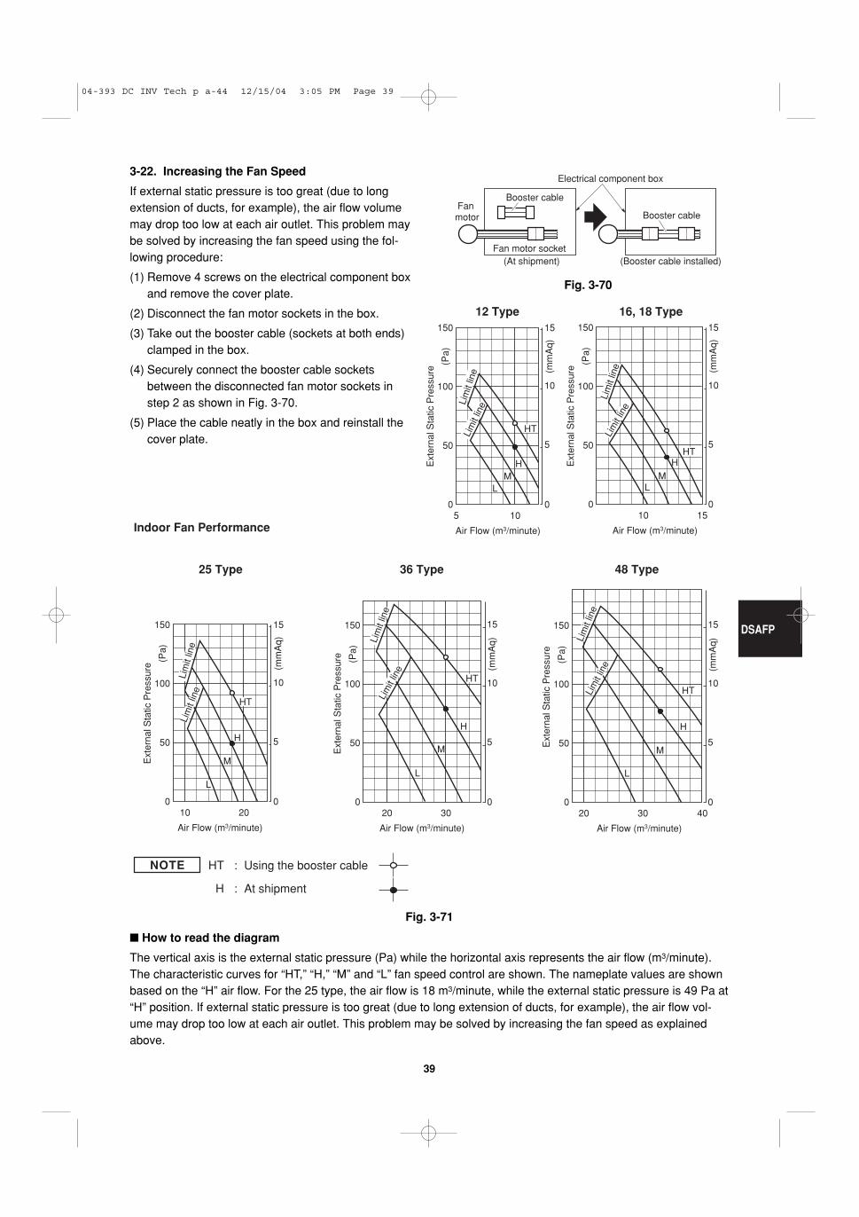
NOTE HT : Using the booster cable
H : At shipment
5
Air Flow (m3/minute)
Ext
erna
l Sta
tic P
ress
ure
0
50
100
0
5
10
15150
10
(mm
Aq)
(Pa)
Lim
it lin
eLim
it lin
e
HT
HM
L
20
Air Flow (m3/minute)
Ext
erna
l Sta
tic P
ress
ure
0
50
0
5
10
15150
10
Lim
it lin
eLi
mit
line
HT
H
L
100
M
(mm
Aq)
(Pa)
30 40
Air Flow (m3/minute)
Ext
erna
l Sta
tic P
ress
ure
0
50
0
5
10
15150
20
Lim
it lin
e
Lim
it lin
e
L
100
M
H
(mm
Aq)
(Pa)
HT
30
Air Flow (m3/minute)
Ext
erna
l Sta
tic P
ress
ure
0
50
0
5
10
15150
20
Lim
it lin
e
HT
L
100
M
H
Lim
it lin
e (mm
Aq)
(Pa)
15
Air Flow (m3/minute)
Ext
erna
l Sta
tic P
ress
ure
0
50
0
5
10
15150
10
Lim
it lin
e
Lim
it lin
e
HT
ML
100
H
(mm
Aq)
(Pa)
16, 18 Type12 Type
Indoor Fan Performance
25 Type 36 Type 48 Type
3-22. Increasing the Fan Speed
If external static pressure is too great (due to longextension of ducts, for example), the air flow volumemay drop too low at each air outlet. This problem maybe solved by increasing the fan speed using the fol-lowing procedure:
(1) Remove 4 screws on the electrical component boxand remove the cover plate.
(2) Disconnect the fan motor sockets in the box.
(3) Take out the booster cable (sockets at both ends)clamped in the box.
(4) Securely connect the booster cable socketsbetween the disconnected fan motor sockets instep 2 as shown in Fig. 3-70.
(5) Place the cable neatly in the box and reinstall thecover plate.
Fig. 3-70
Fig. 3-71
Booster cable
Booster cable
Electrical component box
(At shipment) (Booster cable installed)Fan motor socket
Fan motor
� How to read the diagram
The vertical axis is the external static pressure (Pa) while the horizontal axis represents the air flow (m3/minute).The characteristic curves for “HT,” “H,” “M” and “L” fan speed control are shown. The nameplate values are shownbased on the “H” air flow. For the 25 type, the air flow is 18 m3/minute, while the external static pressure is 49 Pa at“H” position. If external static pressure is too great (due to long extension of ducts, for example), the air flow vol-ume may drop too low at each air outlet. This problem may be solved by increasing the fan speed as explainedabove.
04-393 DC INV Tech p a-44 12/15/04 3:05 PM Page 39
DSAFP
40
4. HOW TO INSTALL THE OUTDOOR UNIT
4-1. Installing the Outdoor Unit
� Use concrete or a similar material to create the base,and ensure good drainage.
� Ordinarily, ensure a base height of 5 cm or more. If adrain pipe is used, or for use in cold-weather regions,ensure a height of 15 cm or more at the feet on bothsides of the unit. (In this case, leave clearance below the unit for thedrain pipe, and to prevent freezing of drainage waterin cold-weather regions.)
� Refer to the Fig. 4-1 for the anchor bolt dimensions.
� Be sure to anchor the feet with the anchor bolts(M10). In addition, use anchoring washers on the topside. (Use large square 32 ( 32 SUS washers withJIS nominal diameters of 10.) (Field supply)
4-2. Drainage Work
Follow the procedure below to ensure adequate drain-ing for the outdoor unit.
� For the drain port dimensions, refer to the figure atright.
� Ensure a base height of 15 cm or more at the feet onboth sides of the unit.
� When using a drain pipe, install the drain socket(optional part STK-DS25T) onto the drain port. Sealthe other drain port with the rubber cap supplied withthe drain socket.
� For details, refer to the instruction manual of thedrain socket (optional part STK-DS25T).
4-3. Routing the Tubing and Wiring
� The tubing and wiring can be extended out in 4 direc-tions: front, rear, right, and down.
� The service valves are housed inside the unit. Toaccess them, remove the inspection panel. (Toremove the inspection panel, remove the 3 screws,then slide the panel downward and pull it toward you.)
(1) If the routing direction is through the front, rear, orright, use a nipper or similar tool to cut out theknockout holes for the inter-unit control wiring outlet,power wiring outlet, and tubing outlet from theappropriate covers A and B.
(2) If the routing direction is down, use a nipper or simi-lar tool to cut out the lower flange from cover A.
Fig. 4-1
942
296
150219
13 13
1920
1510
380
405
341
1313
171 660 111
Drain port (2 locations)
Drain port Anchor bolt (M10)
Fig. 4-2
Inter-unit control wiring outlet
Inspection panel
Cover A Cover B
Power wiring outlet
Tubing outlet
Down
Front
Rear
Right
CAUTION
� Route the tubing so that it doesnot contact the compressor,panel, or other parts inside theunit. Increased noise will result ifthe tubing contacts these parts.
� When routing the tubing, use atube bender to bend the tubes.
04-393 DC INV Tech p a-44 12/15/04 3:05 PM Page 40
41
Control wiring
(C) Inter-unit (between outdoor and indoor units) control wiring
(D) Remote control wiring (E) Control wiring for group control
0.75 mm2 (AWG #18) 0.75 mm2 (AWG #18) 0.75 mm2 (AWG #18)Use shielded wiring* Use shielded wiring Use shielded wiring
Max. 1,000 m Max. 500 m Max. 500 m (Total)
5. ELECTRICAL WIRING
5-1. General Precautions on Wiring
(1) Before wiring, confirm the rated voltage of the unitas shown on its nameplate, then carry out thewiring closely following the wiring diagram.
(2) Provide a power outlet to be used exclusively foreach unit, and a power supply disconnect and cir-cuit breaker for overcurrent protection should beprovided in the exclusive line.
(3) To prevent possible hazards from insulation fail-ure, the unit must be grounded.
(4) Each wiring connection must be done in accor-dance with the wiring system diagram. Wrongwiring may cause the unit to misoperate orbecome damaged.
(5) Do not allow wiring to touch the refrigerant tubing,compressor, or any moving parts of the fan.
(6) Unauthorized changes in the internal wiring can bevery dangerous. The manufacturer will accept noresponsibility for any damage or misoperation thatoccurs as a result of such unauthorized changes.
(7) Regulations on wire diameters differ from localityto locality. For field wiring rules, please refer toyour LOCAL ELECTRICAL CODES before begin-ning.
You must ensure that installation complies with allrelevant rules and regulations.
(8) To prevent malfunction of the air conditionercaused by electrical noise, care must be takenwhen wiring as follows:
� The remote control wiring and the inter-unit controlwiring should be wired apart from the inter-unitpower wiring.
� Use shielded wires for inter-unit control wiringbetween units and ground the shield on both sides.
(9) If the power supply cord of this appliance is dam-aged, it must be replaced by a repair shopappointed by the manufacture, because specialpurpose tools are required.
5-2. Recommended Wire Length and Wire Diameter for Power Supply System
Outdoor unit(A) Power supply
Wire size Max. lengthGRFP255L, GRFP255R 24 m 30 AGRFP365L, GRFP365R 22 m 40 AGRFP485L, GRFP485R 20 m 50 A
4 mm4 mm4 mm
2
2
2
Time delay fuse orcircuit capacity
NOTE
* With ring-type wire terminal.
Indoor unit
Time delay fuse orcircuit capacity
(B) Power supply
2.5 mm2
MAFP
CAFP, SPAFP, DSAFP
Type
Max. 150 m
Max. 130 m
10 A
10 A
04-393 DC INV Tech p a-44 12/15/04 3:05 PM Page 41
42
5-3. Wiring System Diagrams
U2
U1
12
R1
R2
U2
U1
3
R1
R2
U2
U1
R1
R2
U2
U1
R1R2
Group control:
2
1WHT
Remote controller D
A
E
Indoorunit (No. n)
Indoorunit (No. 1)
Indoorunit (No. 2)
Indoorunit (No. 3)
C
B
L
NGround
LN
LN
LN
LN
BLK 2
1
Power supply220-240V 50Hz
B
B
B
Ground
Ground
Ground
Power supply200-240V 50Hz
Power supply220-240V 50Hz
Power supply220-240V 50Hz
Power supply220-240V 50Hz
Ground
CGround
CGround
C
Ground
2
1
N
L
Outdoor unitINV unit
2
1
1
2
3
1
2
3
U1
NOTE
(1) Refer to Section 5-2. “Recommended Wire Lengthand Wire Diameter for Power Supply System” forthe explanation of “A,” “B,” “C,” “D,” and “E,” in theabove diagrams.
(2) The basic connection diagram of the indoor unitshows the 7P terminal board, so the terminalboards in your equipment may differ from the dia-gram.
(3) Refrigerant Circuit (R.C.) address should be setbefore turning the power on.
1(L)2(N)Power supply U1
Inter-unitcontrol wiring
U2Remote controller
8P terminal board
R1 R21 2 U1 U2 R1 R2
DSAFP Type MAFP Type
1(L)2(N)1 2 3 4 5
Power supply
Inter-unitcontrol wiring
5P terminal board
U1 U2
1(L) 2(N)Power supply
U1Inter-unit
control wiring
U2Remote controller
R1 R2
CAFP, SPAFP Type
7P terminal board
04-393 DC INV Tech p a-44 12/15/04 3:05 PM Page 42
43
Outdoor unit Outdoor unit Outdoor unit
Indoor unit Indoor unit Indoor unit Indoor unit
Indoor unit
more than 1 m
more than 1 mBranchpoint
16 or fewer
Indoor unit
Indoor unit Indoor unit Indoor unit
less than 1 m
Indoor unit
Outdoor unit Indoor unit Indoor unit Indoor unit
Indoor unit Indoor unit Indoor unit
Outdoor unit
Indoor unit
NO
NO
Branch point
(1) When linking outdoor units in a network (S-net link system), disconnect the terminal extended from theshort plug (CN003, 2P Black, location: right bottom on the outdoor main control PCB) from all outdoorunits except any one of the outdoor units. (When shipping: In shorted condition.)
Otherwise the communication of S-net link system is not performed. For a system without link (no con-nection wiring between outdoor units), do not remove the short plug.
(2) Do not install the inter-unit control wiring in a way that forms a loop. (Fig. 5-1)
Outdoor unit Outdoor unit Outdoor unitProhibited
Prohibited
Indoor unit Indoor unit Indoor unit Indoor unit Indoor unit
Fig. 5-1
Fig. 5-2
Fig. 5-3
CAUTION
(3) Do not install inter-unit control wiring such as starbranch wiring. Star branch wiring causes mis-addresssetting.
(4) If branching the inter-unit control wiring, the number of branch points should be 16 or fewer. (Branches less than 1 m are not included in the total branch number.) (Fig. 5-3)
04-393 DC INV Tech p a-44 12/15/04 3:05 PM Page 43
44
Fig. 5-4
Shielded wire
Ground Ground
Fig. 5-5
Stranded wire
Ringpressure terminal
Str
ip 1
0 m
m
Fig. 5-6
Wire
Specialwasher Screw
Ring pressure terminal
Terminal plate
Screw and Special washer
Ring pressure terminal
Wire
(5) Use shielded wires for inter-unit control wiring(c) and ground the shield on both sides, other-wise misoperation from noise may occur. (Fig. 5-4)Connect wiring as shown in Section “5-3.Wiring System Diagrams.”
WARNING
Loose wiring may causethe terminal to overheat orresult in unit malfunction.A fire hazard may alsoexist. Therefore, ensurethat all wiring is tightlyconnected.
When connecting each power wire to the terminal, fol-low the instructions on “How to connect wiring to theterminal” and fasten the wire securely with the fixingscrew of the terminal plate.
How to connect wiring to the terminal
� For stranded wiring
(1) Cut the wire end with cutting pliers, then strip theinsulation to expose the stranded wiring about 10mm and tightly twist the wire ends. (Fig. 5-5)
(2) Using a Phillips head screwdriver, remove the ter-minal screw(s) on the terminal plate.
(3) Using a ring connector fastener or pliers, securelyclamp each stripped wire end with a ring pressureterminal.
(4) Place the ring pressure terminal, and replace andtighten the removed terminal screw using a screw-driver. (Fig. 5-6)
04-393 DC INV Tech p a-44 12/15/04 3:05 PM Page 44
45
K
Fig. 6-2
120
120
4
2.7
16
Diagram of outer dimensions
6. HOW TO INSTALL THE REMOTE CONTROLLER (OPTIONAL PART)
Remote controller wiring can be extended to a maxi-mum of 1,000 m.
� How to install the remote controller (Optional Controller)
CAUTION
� Do not twist the controlwiring with the powerwiring or run it in thesame metal conduit,because this may causemalfunction.
� Install the remote con-troller away from sourcesof electrical noise.
� Install a noise filter ortake other appropriateaction if electrical noiseaffects the power supplycircuit of the unit.
The mounting position for the remote controllershould be located in an accessible place for control. Never cover the remote controller or recess it into thewall.
(1) When you open the decorative cover, you will see 2gaps under the remote controller. Insert a coin intothese gaps and pry off the back case. (Fig. 6-1)
6-1. When Using a Wall Box for Flush Mounting
� If local codes allow, this remote controller can bemounted using a conventional wall box for flushmounting.
(2) Attach the back case with the 2 small screws pro-vided. Using a screwdriver, push open the cut-outson the back case. These holes are for screws.Use the spacers and take care not to tighten thescrews excessively. If the back case will not seatwell, cut the spacers to a suitable thickness. (Fig. 6-1)
(3) Connect the remote controller wiring (2 wires) cor-rectly to the corresponding terminals in the electri-cal component box of the indoor unit.
(4) To finish, fit the back tabs of the case into theremote controller and mount it.
CAUTION
When wiring, do not con-nect the remote controllerwires to the adjacent termi-nal block for the powerwiring. Otherwise, the unitwill break down.
CAUTION
Do not supply power to theunit or try to operate it untilthe tubing and wiring to theoutdoor unit is completed.
Fig. 6-1
Opening for switch box
Under case(Back case)
M4 × 25screws (2)
Remotecontroller Decorative
cover
Spacer
1
2 2
3 2
Remote controller switch
(with 200 mm wire)
Small screwsM4 × 25
Wood screws
4 2
5 2
Spacers
Wire joints
1
Accompanying partsAccompanying parts No.No. Q’tyQ’ty
Accessories for remote controller switch
Unit: mm
04-393 DC INV Tech p 45-63 12/13/04 11:34 AM Page 45
CAUTIONInstall wiring correctly(incorrect wiring will dam-age the equipment).
� Use shielded wires for remote control wiring andground the shield on one side. (Fig. 6-3) Otherwisemisoperation due to noise may occur.
Fig. 6-3Fig. 6-4
Shielded wire
Ground
6-3. Wiring System Diagram for Group Control
This diagram shows when several units (maximum of4) are controlled by a remote controller (master unit).In this case, a remote controller can be connected atany indoor unit.
Wiring procedure
Wire according to the right diagram:
� Each successive unit will respond at 1-secondintervals following the order of the group addresswhen the remote controller is operated.
Group control using 2 remote controllers
It does not matter which of the 2 remote controllersyou set as the main controller.
When using multiple remote controllers (up to 2 canbe used), one serves as the main remote controllerand the other as the sub-remote controller.
1 2
1
1 2
1 2
1
1 2
1
1 2
1
Outdoor unit
Indoor unitNo. 4
Indoor unitNo. 3
Indoor unitNo. 2
Indoor unitNo. 1
1
Remotecontroller
Connection wiring forgroup control
Inter-unitcontrolwiring
Terminal3P
2
2 2 2 2
(sub)
3P terminal base for remote control wiring
Remotecontroller(main)
1Indoor unit
No. 1
: Ground (earth)
Indoor unitNo. 2
Indoor unitNo. 4
Indoor unitNo. 3
Connection wiring for group control
1 1
1 2
2 2 21
21
2
Fig. 6-5
04-393 DC INV Tech p 45-63 12/13/04 11:34 AM Page 46
47
K
Cautions on group control
� Group control within the same refrigerant tub-ing system is recommended.
[Tubing system which is NOT recommended]
<Example 1> In this system, group control extendingover tubing systems becomes impossi-ble to set, which means the indoor unitscannot operate.
NOTE
1 2 3 4
Tubing system 2Tubing system 1
Indoor units
Remote controller
TIMERTMNL.
RCUTMNL. RCU.ADR
RCU.Main
RCU.SubRCU.CK
To Service TechniciansTo display the sensor temperature:
WARNINGTo avoid an e lect r ic shock hazard,DO NOT touch any ter -mina l on the Pr in ted Ci r -cu i t Board wi th a meta l rod, ascrewdr iver edge or bare handwhen power is suppl ied.
Press both and buttons on the remote controller for more than 4 seconds together.Change the sensor address (CODE NO.) with / (SET TEMP) buttons.Select the UNIT NO. that you want to call with button.Press the button to finish service mode.
To display the trouble history:Press both and buttons on the remote controller for more than 4 seconds together.Change the alarm message: / (SET TEMP) buttonsCODE NO.
Press the button to finish service mode.
On the remote controller, press + + at the same time for more than 4 seconds.Set CODE No. with /(SET TEMP) button.
Set DATA from towith / (TIMER) button.PressFinally, Press
(New) (Old)
Changing method for room temperature sensor (from Indoor unit to RCU)
1
2
3
4
Remote Controller (Sub)
Remote controller address connector
Remote Controller (Main)
Setting the main and sub remote controllers
1. Set one of the 2 connected remote controllers as the main remote controller.
2. On the other remote controller (sub-remote controller), switch the remote controller address connector on therear of the remote controller PCB from Main to Sub. When the connector has been switched, the remote con-troller will function as the sub-remote controller.
Fig. 6-6
04-393 DC INV Tech p 45-63 12/13/04 11:34 AM Page 47
48
K
6-4. Switching the Room Temperature Sensors
Room temperature sensors are contained in the indoor unit and in the remote controller. One or the other of the temperature sensors is used for operation. Normally, the indoor unit sensor is set; however,the procedure below can be used to switch to the remote controller sensor.
(1) Press and hold the + + buttons for 4 seconds or longer.
� The unit No. that is initially displayed is the indoor unit address of the group control master unit.
� Do not press the button.
(2) Use the temperature setting / buttons to select item code 32.
(3) Use the timer time / buttons to change the setting data from 0000 to 0001.
(4) Press the button. (The change is completed when the display stops blinking.)
(5) Press the button.
The unit returns to normal stop status. At this time, “Remote controller sensor” is displayed on the LCD.
� If 2 remote controllers are used for control, this setting can be made from either the main or sub remote con-troller. However, the temperature sensor that is used is the sensor in the main remote controller.
� When group control is used, the remote controller sensor will not function unless the group address is set to theaddress of the master indoor unit.
� If both the remote sensor and remote controller are used, do not use the temperature sensor in the remote con-troller.
6-5. Connecting to a Ventilation Fan
If a commercially available ventilation fan or similar device is run from the ventilation fan output terminal (FANDRIVE: 2P (white), DC 12 V) (Note) on the indoor unit PCB, use the button to enable fan operation andchange the settings.
(1) Press and hold the + + buttons for 4 seconds or longer.
� The unit No. that is initially displayed is the indoor unit address of the group control master unit.
� Do not press the button.
(2) Use the temperature setting / buttons to select item code 31.
(3) Use the timer time / buttons to change the setting data from 0000 to 0001.
(4) Press the button. (The change is completed when the display stops blinking.)
(5) Press the button.
The unit returns to normal stop status. Press the button and check that “Fan” is displayed on the LCD display.
(Note) A special relay is required to run the ventilating fan.
NOTE
NOTE
NOTE
1 12 2
Relay (DC12V, field supply)External control input for ventilation fan
Indoor unit control PCB
FAN DRIVE(2P white) To terminal
NOTE: The wiring from the indoor unit control PCB to the relay must be no more than 2 m in length.
04-393 DC INV Tech p 45-63 12/13/04 11:34 AM Page 48
49
K
6-6. Wiring the Remote Controller
<Flush Mounting>
� Connection diagram
� Use 0.5 mm2 – 2 mm2 wires.
(1) Strip the insulation to approximately 14 mm fromthe ends of the wires that will be connected.
(2) Twist together the 2 wires and create a crimp con-nection at the wire joint.
(3) If a special crimping tool is not used, or if the con-nection is soldered, insulate the wires using insu-lation tape.
� Use the remote controller cord (optional) for remotecontroller wiring.
(1) Disconnect the lead wire that is wound around thelead wire anchor on the remote controller unit. Dis-connect the connector and connect the remotecontroller cord (optional) to the connector on theremote controller unit. Insert the remote controllercord (optional) into the groove and bend it into thecorrect shape, then wind it around the lead wireanchor.
(2) If the remote controller cord (optional) is used,refer to the installation manual that is providedwith the cord.
Terminal board for indoor unit remote controller wiring
12
12
WBK
Remote controller wiring (field supply)
Connector
Remote controller unit
Power wire from remote controller unit
Approx. 200 mm
Remote controller wiring
Power wire from remote controller unit
Provided wire joint (white)
Wire jointCE-1, white
Remote controller cord (optional)
Connector Lead wire anchor
04-393 DC INV Tech p 45-63 12/13/04 11:34 AM Page 49
50
K
6-7. Trouble Diagnostics
(1) Contents of remote controller switch alarm display
Remote controller is detecting error signal from indoor unit
E01
E02
E10
E11
E14
E03
E08
E09
E04
E05
E06
E07
E15
E16
E20
E17
E18
E31
L01
L02
L03
L04
L07
L08
L09
L010
L011
L013
Indoor unit is detecting error signal from remote controller (and system controller)
Error in receiving serial communication signal(Signal from main indoor unit in case of group control)
Auto address is not completed
Outdoor system address, indoor system address, or indoor unit individual/main/sub setting is not set (Automatic address setting is not completed)
Error in transmitting serial communication signal
Improper setting of indoor unit or remote controller
Indoor unit address setting is duplicated
Remote controller setting is duplicated
Error in transmitting serial communications signal
Error in transmitting serial communications signal
Error in receiving serial communications signal
Error in receiving serial communications signal
Indoor unit is detecting error signaled from signal option
Setting error Main unit duplication in simultaneous-operation multi control (detected by outdoor unit)
Indoor unit is detecting error signaled from outdoor unit
Outdoor unit is detecting error signaled from indoorunit
Automatic address setting failed
An indoor unit detected trouble in the signal from another indoor unit
Communications trouble between units
Setting errorMis-setting
Continued
Error in transmitting serial communications signal
Indoor unit capacity too low
Indoor unit capacity too high
No indoor units connected
Error in receiving serial communications signal
Communications failure with MDC
Indoor unit group settings error
Indoor/outdoor unit type mismatch
Main unit duplication in group control (detected by indoor unit)
Outdoor unit address duplication (system address)
Group wiring connected for independent indoor unit
Address not set or group not set
Indoor unit capacity not set
Outdoor unit capacity not set or setting error
Miswiring in group control wiring
Indoor unit type setting error (capacity)
Error in transmitting serial communications signal
Error in receiving serial communications signal (including unit quantity verification failure)
Simultaneously
Simultaneously
Simultaneously
Simultaneously
Serial commu-nication errorsMis-setting
Wiredremotecontroldisplay
Wirelessremote controllerreceiver display
Op
erat
ion
Tim
er
Sta
nd
by
for
hea
tin
gPossible cause of malfunction
04-393 DC INV Tech p 45-63 12/13/04 11:34 AM Page 50
51
K
P09
P01
P10
P03
P05
P15
P19
P20
P22
P26
P29
P31
H01
F01
F02
F10
F04
F06
F07
F08
F12
F29
Ceiling panel connection failure
Indoor protection Fan protective thermostat
Float switch
Discharge temperature trouble
Open phase detected, AC power trouble
No gas
4-way valve locked
High cooling load
Outdoor fan trouble
Inverter compressor trouble (HIC PCB)
Inverter compressor trouble (MDC)
Simultaneous-operation multi control trouble
Compressor current failure (overload)
Indoor heat exchanger temperature sensor (E1)
Indoor heat exchanger temperature sensor (E2)
Indoor temperature sensor
Discharge temperature (TD)
Outdoor heat exchanger temperature (C1)
Outdoor heat exchanger temperature (C2)
Outdoor air temperature (TO)
Intake temperature (TS)
Indoor EEPROM error
Outdoor protection
Thermistor open circuit• Short circuit (indoor)
Thermistor open circuit• Short circuit (outdoor)
Activation ofprotectivedevice
Thermistorfault
Alternately
Alter.
Simul.
Alter.
Simul.
Alternately
Outdoor EEPROM error F31
Wiredremotecontroldisplay
Wirelessremote controllerreceiver display
ON:
Op
erat
ion
Tim
er
Sta
nd
by
for
hea
tin
g
Blinking: OFF:
Possible cause of malfunction
04-393 DC INV Tech p 45-63 12/13/04 11:34 AM Page 51
52
K
(2) LED Indicator Messages on Outdoor Control PCB
Power ON sequence1. No communication from indoor units in system
2. Communication received from 1 or more indoor units in system
3. Regular communication OK (Capacity and unit quantity match)
If it is not possible to advance to 3, repeats 1 → 2.At 3, changes to normal control.
P03
Normal operation
Pre-trip (insufficient gas)
Pre-trip (P20)
Pre-trip (other)
Automatic address setting in progress
Automatic address setting alarm (E15)
Automatic address setting alarm (E20)
Automatic address setting alarm (Other than E15 and E20)
Note: This table shows example alarms. Other alarms may also be displayed.
(0.25/0.75)
(0.75/0.25)
EEPROM error (F31)
Blinking alternately
Blinking simultaneously
Blinking simultaneously
Blinking simultaneously
AlarmLED 1 blinks M times, then LED 2 blinks N times.The cycle then repeats.
M = 2: P alarm 6: L alarmN = Alarm No. * Refer to “1. Examples of alarm display” below.
3: H alarm 4: E alarm 5: F alarm
Alternate blinking during alarms
Insufficient gas indicator
(0.25/0.75)
(0.75/0.25)
(0.25/0.75)
(0.75/0.25)
Refrigerant recovery mode
Automatic address setting
Displayed during automatic address setting 1 and initial communication. After these are completed, alarm F31 is displayed.
P03
P04
P05
P31
H01
H02
H03
•
E04
•
F07
•
L13
•
( Blinks 2 times )
( " )
( " )
( " )
(Blinks 3 times)
( " )
( " )
•
(Blinks 4 times)
•
(Blinks 5 times)
3
(Blinks 6 times)
•
(Blinks 3 times)
(Blinks 4 times)
(Blinks 5 times)
(Blinks 31 times)
(Blinks 1 times)
(Blinks 2 times)
(Blinks 3 times)
(Blinks 4 times)
(Blinks 7 times)
(Blinks 13 times)
Alarm / Display LED 1 Alternately
→ → LED 2
ON:
:
:
LED 1 LED 2 Remarks
OFF
(3) Examples of alarm display (other than E15, E16, and E20)
Blinking (0.25/0.75) indicates that the lamp illuminates for 0.25 seconds, and then is OFF for 0.75 seconds. Unless otherwise indicated, the blinking is (0.5/0.5).
04-393 DC INV Tech p 45-63 12/13/04 11:34 AM Page 52
53
7. HOW TO PROCESS TUBING
The narrow tubing side is connected by a flare nut,and the wide tubing side is connected by brazing.
7-1. Connecting the Refrigerant Tubing
Use of the Flaring Method
Many of conventional split system air conditionersemploy the flaring method to connect refrigerant tubeswhich run between indoor and outdoor units. In thismethod, the copper tubes are flared at each end andconnected with flare nuts.
Flaring Procedure with a Flare Tool
(1) Cut the copper tube to the required length with atube cutter. It is recommended to cut approx. 30– 50 cm longer than the tubing length you esti-mate.
(2) Remove burrs at each end of the copper tubingwith a tube reamer or file. This process is impor-tant and should be done carefully to make a goodflare. Be sure to keep any contaminants (moisture,dirt, metal filings, etc.) from entering the tubing.(Figs. 7-1 and 7-2)
When reaming, hold the tube end downward and besure that no copper scraps fall into the tube. (Fig. 7-2)
(3) Remove the flare nut from the unit and be sure tomount it on the copper tube.
(4) Make a flare at the end of the copper tube with aflare tool.* (Fig. 7-3)
*Use “RIGID®” or equivalent.
A good flare should have the following characteristics:
� inside surface is glossy and smooth
� edge is smooth
� tapered sides are of uniform length
NOTE
NOTE
Deburring
Before After
Fig. 7-1
Reamer
Coppertubing
Fig. 7-2
Flare tool
Flare nut
Copper tubing
Fig. 7-3
A
φ6.35
φ9.52
φ12.7
φ15.88
9.1
13.2
16.6
19.7
A 0– 0.4
Copper tubing(Outer dia.)
Flare size: A (mm)
04-393 DC INV Tech p 45-63 12/13/04 11:34 AM Page 53
54
Fig. 7-7
Caution Before Connecting Tubes Tightly
(1) Apply a sealing cap or water-proof tape to preventdust or water from entering the tubes before theyare used.
(2) Be sure to apply refrigerant lubricant to the match-ing surfaces of the flare and union before connect-ing them together. This is effective for reducinggas leaks. (Fig. 7-4)
(3) For proper connection, align the union tube andflare tube straight with each other, then screw onthe flare nut lightly at first to obtain a smoothmatch. (Fig. 7-5)
� Adjust the shape of the narrow tube (liquid tube)using a tube bender at the installation site andconnect it to the narrow tubing side (liquid tubingside) valve using a flare.
Cautions During Brazing
� Replace air inside the tube with nitrogen gas toprevent copper oxide film from forming duringthe brazing process. (Oxygen, carbon dioxideand Freon are not acceptable.)
� Do not allow the tubing to get too hot duringbrazing. The nitrogen gas inside the tubingmay overheat, causing refrigerant systemvalves to become damaged. Therefore allowthe tubing to cool when brazing.
� Use a reducing valve for the nitrogen cylinder.
� Do not use agents intended to prevent the for-mation of oxide film. These agents adverselyaffect the refrigerant and refrigerant oil, andmay cause damage or malfunctions.
7-2. Connecting Tubing Between Indoor and Outdoor Units
(1) Tightly connect the indoor-side refrigerant tubingextended from the wall with the outdoor-side tubing.
(2) To fasten the flare nuts, apply specified torque asat right.
� When removing the flare nuts from the tubing con-nections, or when tightening them after connectingthe tubing, be sure to use 2 monkey wrenches orspanners as shown. (Fig. 7-6) If the flare nuts are over-tightened, the flare may bedamaged, which could result in refrigerant leakageand cause injury or asphyxiation to room occupants.
� When removing or tightening the wide tube flarenut, use 2 monkey wrenches together: one at thewide tube flare nut, and one at part A. (Fig. 7-7)
� For the flare nuts at tubing connections, be sure touse the flare nuts that were supplied with the unit,or else flare nuts for R410A (type 2). The refriger-ant tubing that is used must be of the correct wallthickness as shown in the table at right.
Apply refrigerant lubricant here and here
Fig. 7-4
Flare nutUnion
Fig. 7-5
Fig. 7-6
Indoor unit
Outdoor unit
Spanner
Torque wrench
Tube diameter
φ6.35 (1/4")
φ9.52 (3/8")
φ12.7 (1/2")
φ15.88 (5/8")
Tightening torque(approximate)
14 – 18 N · m(140 – 180 kgf · cm)
34 – 42 N · m(340 – 420 kgf · cm)
49 – 61 N · m(490 – 610 kgf · cm)
68 – 82 N · m(680 – 820 kgf · cm)
0.8 mm
0.8 mm
0.8 mm
1.0 mm
Tube thickness
Because the pressure is approximately 1.6 timeshigher than conventional refrigerant pressure, theuse of ordinary flare nuts (type 1) or thin-walledtubes may result in tube rupture, injury, or asphyxi-ation caused by refrigerant leakage.
� In order to prevent damage to the flare caused byover-tightening of the flare nuts, use the tableabove as a guide when tightening.
� When tightening the flare nut on the narrow tube,use a monkey wrench with a nominal handle lengthof 200 mm.
A
04-393 DC INV Tech p 45-63 12/13/04 11:34 AM Page 54
55
Fig. 7-10
Fig. 7-9
Fig. 7-8
Fig. 7-11
� Do not use a spanner to tighten the valve stemcaps. Doing so may damage the valves.
� Depending on the installation conditions, applyingexcessive torque may cause the nuts to crack.
Precautions for Packed Valve Operation
� If the packed valve is left for a long time with thevalve stem cap removed, refrigerant will leak fromthe valve. Therefore, do not leave the valve stemcap removed.
� Use a torque wrench to securely tighten the valvestem cap.
� Valve stem cap tightening torque:
7-3. Insulating the Refrigerant Tubing
Tubing Insulation
� Thermal insulation must be applied to all unit tub-ing, including distribution joint (purchased sepa-rately). * For gas tubing, the insulation material must be
heat resistant to 120°C or above. For other tubing,it must be heat resistant to 80°C or above.
Insulation material thickness must be 10 mm orgreater.If the conditions inside the ceiling exceed DB 30°Cand RH 70%, increase the thickness of the gastubing insulation material by 1 step.
Taping the flare nuts
Wind the white insulation tape around the flare nuts atthe wide tube connections. Then cover up the tubingconnections with the flare insulator, and fill the gap atthe union with the supplied black insulation tape.Finally, fasten the insulator at both ends with the sup-plied vinyl clamps. (Fig. 7-10)
Insulation material
The material used for insulation must have good insu-lation characteristics, be easy to use, be age resis-tant, and must not easily absorb moisture.
After a tube has been insu-lated, never try to bend itinto a narrow curvebecause it can cause thetube to break or crack.
CAUTION
CAUTION
Never grasp the drain or refrigerant connectingoutlets when moving the unit.
Unit sideinsulator
Insulation tape (white)(supplied)
Sealer (supplied)
Flare insulator (supplied)
Tube insulator(not supplied)Heat resistant120°C or above
Vinyl clamps (supplied)Flare nut
The procedure used forinstalling the insulator forboth wide and narrowtubes is the same.
Seal
Flareinsulator
Vinylclamp
Insulationtape
Refrigerant tubing and insulator(not supplied)
Drain pipe and insulator(not supplied)
Drain insulatorand clamp.Large(supplied)
Packingclamp.Smallhose band(supplied)
Two tubes arranged together
If the exterior of the outdoorunit valves has been finishedwith a square duct covering,make sure you allow sufficientspace to access the valves andto allow the panels to beattached and removed.
Charging port 8 – 10 N • m (80 – 100 kgf • cm)
φ9.52 (Narrow side) 19 – 21 N • m (190 – 210 kgf • cm)
φ15.88 (Wide side) 28 – 32 N • m (280 – 320 kgf • cm)
Inter-unit control wiring
Wide tubeNarrow tube
Armoring tape
Insulation
Charging port
Valve stem cap
Valve stem
Main valve
Packed valve
04-393 DC INV Tech p 45-63 12/13/04 11:34 AM Page 55
56
GRFP
Fig. 7-12
Fig. 7-13
7-4. Taping the Tubes
(1) At this time, the refrigerant tubes (and electricalwiring if local codes permit) should be tapedtogether with armoring tape in 1 bundle. To pre-vent condensation from overflowing the drainpan, keep the drain hose separate from therefrigerant tubing.
(2) Wrap the armoring tape from the bottom of theoutdoor unit to the top of the tubing where itenters the wall. As you wrap the tubing, overlaphalf of each previous tape turn.
(3) Clamp the tubing bundle to the wall, using 1clamp approx. each meter. (Fig. 7-12)
Do not wind the armoring tape too tightly since thiswill decrease the heat insulation effect. Also ensurethat the condensation drain hose splits away from thebundle and drips clear of the unit and the tubing.
7-5. Finishing the Installation
After finishing insulating and taping over the tubing,use sealing putty to seal off the hole in the wall to pre-vent rain and draft from entering. (Fig. 7-13)
NOTE
Inter-unit control wiring
Wide tubeNarrow tube
Armoring tape
Insulation
Tubing
Apply putty here
04-393 DC INV Tech p 45-63 12/13/04 11:34 AM Page 56
57
GRFP
Fig. 8-1
Fig. 8-2
Fig. 8-3
8. LEAK TEST, EVACUATION AND ADDITIONAL REFRIGERANT CHARGE
� Perform an air-tightness test for this package A/C.Check that there is no leakage from any of the con-nections. Air and moisture in the refrigerant system mayhave undesirable effects as indicated below.
� pressure in the system rises� operating current rises� cooling (or heating) efficiency drops� moisture in the refrigerant circuit may freeze and
block capillary tubing� water may lead to corrosion of parts in the refriger-
ant system
Therefore, the indoor unit and tubing between theindoor and outdoor unit must be leak tested andevacuated to remove any noncondensables andmoisture from the system.
� Air Purging with a Vacuum Pump (for Test Run)Preparation
Check that each tube (both narrow and wide tubes)between the indoor and outdoor units has been prop-erly connected and all wiring for the test run has beencompleted. Remove the valve caps from both thewide and narrow service valves on the outdoor unit.Note that both narrow and wide tube service valveson the outdoor unit are kept closed at this stage.
� The refrigerant charge at the time of shipment isonly guaranteed sufficient for a tubing length of upto 30 m. The tubing may exceed this length, up tothe maximum permitted length; however, an addi-tional charge is necessary for the amount that thetubing exceeds 30 m. (No additional refrigeratingmachine oil is needed.)
8-1. Leak Test
(1) With the service valves on the outdoor unit closed,remove the 1/4 in. flare nut and its bonnet on thewide tube service valve. (Save for reuse.)
(2) Attach a manifold valve (with pressure gauges)and dry nitrogen gas cylinder to this service portwith charge hoses.
Manifold gauge
OutletInlet
Vacuum pump
Manifold valve
Pressuregauge Lo Hi
Charge hose
Outdoor unitNarrow tube
Wide tube
Nitrogen gas cylinder(In vertical standingposition)
Close
Close
Open
Cylinder valve
CAUTION
Use a manifold valve forair purging. If it is notavailable, use a stop valvefor this purpose. The “Hi”knob of the manifold valvemust always be keptclosed.
04-393 DC INV Tech p 45-63 12/13/04 11:34 AM Page 57
58
GRFP
Fig. 8-4
(3) Pressurize the system up to 4.15 MPa (42kgf/cm2G) with dry nitrogen gas and close the cylin-der valve when the gauge reading reaches 4.15MPa (42 kgf/cm2G). Then, test for leaks with liquidsoap.
(4) Do a leak test of all joints of the tubing (bothindoor and outdoor) and both wide and narrowservice valves. Bubbles indicate a leak. Wipe offthe soap with a clean cloth after a leak test.
(5) After the system is found to be free of leaks,relieve the nitrogen pressure by loosening thecharge hose connector at the nitrogen cylinder.When the system pressure is reduced to normal,disconnect the hose from the cylinder.
8-2. Evacuation
Be sure to use a vacuum pump that includes a func-tion for prevention of back-flow, in order to preventback-flow of pump oil into the unit tubing when thepump is stopped.
� Perform vacuuming of the indoor unit and tubing. Connect the vacuum pump to the wide tube valveand apply vacuum at a pressure of –755 mmHg (5torr) or below. Continue vacuum application for a minimum of 1hour after the pressure reaches –755 mmHg.)
(1) Attach the charge hose end described in the pre-ceding steps to the vacuum pump to evacuate thetubing and indoor unit. Confirm that the “Lo” knobof the manifold valve is open. Then, run the vacu-um pump.
(2) When the desired vacuum is reached, close the“Lo” knob of the manifold valve and turn off thevacuum pump. Confirm that the gauge pressure isunder 667 Pa (–755 mmHg, 5 Torr) after 4 to 5minutes of vacuum pump operation.
Manifold valve
Pressuregauge Lo Hi
Vacuum pump
Outdoor unitNarrow tube
Wide tube
Close
Close
Open
CAUTION
To avoid nitrogen enteringthe refrigerant system in aliquid state, the top of thecylinder must be higher thanthe bottom when you pres-surize the system. Usually,the cylinder is used in a ver-tical standing position.
CAUTIONUse a cylinder specificallydesigned for use with R410A.
04-393 DC INV Tech p 45-63 12/13/04 11:34 AM Page 58
59
GRFP
Fig. 8-5
Fig. 8-6
8-3. Charging Additional Refrigerant
� Charging additional refrigerant (calculated from thenarrow tube length as shown in P. 12, Amount ofadditional refrigerant charge) using the narrow tubeservice valve. (Fig. 8-5)
� Use a balance to measure the refrigerant accurately.
� If the additional refrigerant charge amount cannotbe charged at once, charge the remaining refriger-ant in liquid form by using the wide tube servicevalve with the system in Cooling mode at the timeof test run. (Fig. 8-6)
* If an additional refrigerant charge has been per-formed, list the refrigerant tubing length andamount of additional refrigerant charge on theproduct label (inside the panel).
8-4. Finishing the Job
(1) With a hex wrench, turn the narrow tube servicevalve stem counter-clockwise to fully open thevalve.
(2) Turn the wide tube service valve stem counter-clockwise to fully open the valve.
(3) Loosen the charge hose connected to the widetube service port (5/16 in.) slightly to release thepressure, then remove the hose.
(4) Replace the 5/16 in. flare nut and its bonnet on thewide tube service port and fasten the flare nutsecurely with an adjustable wrench or box wrench.This process is very important to prevent gas fromleaking from the system.
(5) Replace the valve caps at both wide and narrowservice valves and fasten them securely.
CAUTION
To avoid gas from leakingwhen removing the chargehose, make sure the stem ofthe wide tube is turned allthe way out (“BACK SEAT”position.
Valve
Liquid
Manifold valve
Pressuregauge Lo Hi
Outdoor unitNarrow tube
Wide tube
Close
Close
Close
R410A
Outdoor unitNarrow tube
Wide tube
Open
Open
Open
04-393 DC INV Tech p 45-63 12/13/04 11:34 AM Page 59
60
CAFP
9. HOW TO INSTALL THE CEILING PANEL
� 4-Way Air Discharge Semi-Concealed Type (CAFP Type)
Checking the unit position
(1) Check that the ceiling hole is within this range:860 × 860 to 910 × 910 mm
(2) Use the full-scale installation diagram (from thepackaging) that was supplied with the unit to deter-mine the positioning of the unit on the ceiling sur-face. If the positions of the ceiling surface and unitdo not match, air leakage, water leakage, flapoperation failure, or other problems may result.
CAUTION
� Never place the panelface-down. Either hang itvertically or place it ontop of a projectingobject. Placing it face-down will damage thesurface.
� Do not touch the flap orapply force to it. (This may cause flapmalfunction.)
must be within the range of 12 – 17 mm.If not within this range, malfunction or other trouble may result.A
Ceiling side
Main unit
Ceiling opening dimension
A
Fig. 9-1
Wing
Fig. 9-2
Fig. 9-3
2
Fig. 9-5
9-1. Before Installing the Ceiling Panel
(1) Remove the air-intake grille and air filter from theceiling panel. (Figs. 9-3, 9-4 and 9-5)
a) Remove the 2 screws on the latch of the air-intake grille. (Fig. 9-3)
b) Slide the air-intake grille catches in the direc-tion shown by the arrows to open the grille.(Fig. 9-4)
c) With the air-intake grille opened, remove thegrille hinge from the ceiling panel by sliding it inthe direction shown by the arrow . (Fig. 9-5)
(2) Removing the corner cover
a) Slide the corner cover to the direction shownby the arrow to remove the corner cover. (Fig. 9-6).
1
2
1
Corner cover
Ceiling panel
Strap
Push
1
Corner cover
Fig. 9-6
Air-intake grille Ceiling panel
Air-intake grille hinge
11
Fig. 9-4
LatchScrew
04-393 DC INV Tech p 45-63 12/13/04 11:34 AM Page 60
61
CAFP
CAUTION
9-2. Installing the Ceiling Panel
The power must be turned ON in order to change theflap angle. (Do not attempt to move the flap by hand.Doing so may damage the flap.)
(1) Insert the temporary fasteners (stainless steel) onthe inside of the ceiling panel into the squareholes on the unit to temporarily fasten the ceilingpanel in place. (Fig. 9-7)
� The ceiling panel must be installed in the correctdirection relative to the unit. Align the REF. PIPEand DRAIN marks on the ceiling panel corner withthe correct positions on the unit.
� To remove the ceiling panel, support the ceilingpanel while pressing the temporary fastenerstoward the outside. (Fig. 9-7)
(2) Align the panel installation holes and the unitscrew holes.
(3) Tighten the supplied washer head screws at the 4panel installation locations so that the panel isattached tightly to the unit. (Fig. 9-8)
(4) Check that the panel is attached tightly to the ceil-ing.
� At this time, make sure that there are no gapsbetween the unit and the ceiling panel, or betweenthe ceiling panel and the ceiling surface. (Fig. 9-9)
Square hole in unit
Temporary fastener
Push when you remove Temporary
fastener
Fig. 9-7
Drain tubing corner
Refrigerant tubing corner
Panel installation hole (4 locations)
Ceiling panel
Washer head screws
DRAIN mark
REF. PIPE mark
Fig. 9-8
Do not allowgaps
Ceiling panel
Main unit
Ceiling surface
Fig. 9-9
Insert a wrench or other tool into the corner cover installation hole and make fine adjustments to the unit nut.
Air leakage
Air leakage from ceiling surface
Staining
Condensation, water leakage
Adjust so that there are no gaps.
Fig. 9-10
Fig. 9-11
� If there is a gap between the panel and the ceiling,leave the ceiling panel attached and make fineadjustments to the installation height of the unit toeliminate the gap with the ceiling. (Fig. 9-10)
� If the screws are not sufficientlytightened, trouble such as thatshown in the figure below mayoccur. Be sure to tighten thescrews securely.
� If a gap remains between theceiling surface and the ceilingpanel even after the screwsare tightened, adjust theheight of the unit again.
The height of the unit can be adjusted fromthe ceiling panel corner hole, with the ceil-ing panel attached, to an extent that doesnot affect the unit levelness, the drain hose,or other elements.
04-393 DC INV Tech p 45-63 12/13/04 11:34 AM Page 61
62
CAFP
9-3. Wiring the Ceiling Panel
(1) Open the cover of the electrical component box.
(2) Connect the 7P wiring connector (red) from theceiling panel to the connector in the unit electricalcomponent box.
� If the connectors are not connected, Auto flap willnot operate. Be sure to connect them securely.
� Check that the wiring connector is not caughtbetween the electrical component box and thecover.
� Check that the wiring connector is not caughtbetween the unit and the ceiling panel.
9-4. How to Attach the Corner & Air Intake Grille
Attaching the corner cover and air-intake grille
A. Attaching the corner cover
(1) Check that the safety cord from the corner cover isfastened to the ceiling panel pin, as shown in thefigure.
(2) Use the supplied screws to attach the cornercover to the ceiling panel.
B. Attaching the air-intake grille
� To install the air-intake grille, follow the steps forRemoving the grille in the reverse order. By rotat-ing the air-intake grille, it is possible to attach thegrille onto the ceiling panel from any of 4 direc-tions. Coordinate the directions of the air-intakegrilles when installing multiple units, and changethe directions according to customer requests.
� When attaching the air-intake grille, be carefulthat the flap lead wire does not become caught.
� Be sure to attach the safety cord to the ceilingpanel unit as shown in the figure at right. Thiskeeps the air intake grille from accidentallydropping
(Direction that the unit faces has been changed to facilitate explanation.)
Ceiling panel wiring connector
Ceiling panel side
Screws(3 locations)
Mains side
Clamp
Electrical component box cover
* Pass the wiring connector through the clamp to fasten it in place, as shown in the figure.
Place the corner cover so that the 3 tabsfit into the holes in the ceiling panel. Then fasten it in place with the supplied screws.
Pin
� With this ceiling panel, the directions of the air-intake grille lattices when installing multiple units, and the positionof the label showing the company name on the corner panel, can be changed according to customer requests,as shown in the figure below. However, the optional wireless receiver kit can only be installed at the refrigerant-tubing corner of the ceiling unit.
Unit electrical component box
Unit drain hose side Unit refrigerant tube side
Optional wireless receiver kit* Can only be installed in this position.
Can be installed rotated 90˚
Locations of the air-intake grille catches at the time the product is shipped.* The grille can be installed with these
catches facing in any of 4 directions.
Fig. 9-12
Fig. 9-13
Hole for ceiling panel hook
Hook that prevents the grille from dropping
Fig. 9-14
Fig. 9-15
04-393 DC INV Tech p 45-63 12/13/04 11:34 AM Page 62
63
CAFP
9-5. Checking After Installation
� Check that there are no gaps between the unit andthe ceiling panel, or between the ceiling panel andthe ceiling surface. Gaps may cause water leakage and condensation.
� Check that the wiring is securely connected. If it is not securely connected, the auto flap will notoperate. (“P09” is displayed on the remote con-troller.) In addition, water leakage and condensa-tion may occur.
9-6. When Removing the Ceiling Panel for Servicing
When removing the ceiling panel for servicing,remove the air-intake grille and air filter, disconnectthe wiring connector inside the electrical componentbox, and then remove the 4 mounting screws.
9-7. Adjusting the Auto Flap
The air-direction louver on the ceiling panel outlet canbe adjusted as follows.
� Adjust the louver to the desired angle using theremote controller. The louver also has an automaticair-sweeping mechanism.
� Never attempt to move the louver by hand.
� Proper air flow depends on the location of the airconditioner, the layout of the room and furniture,etc. If cooling or heating seems inadequate, trychanging the direction of the air flow.
NOTE
04-393 DC INV Tech p 45-63 12/13/04 11:34 AM Page 63
64
10. TEST RUN
10-1. Preparing for Test Run
� Before attempting to start the air conditioner,check the following:
(1) All loose matter is removed from the cabinet espe-cially steel filings, bits of wire, and clips.
(2) The control wiring is correctly connected and allelectrical connections are tight.
(3) The protective spacers for the compressor usedfor transportation have been removed. If not,remove them now.
(4) The transportation pads for the indoor fan havebeen removed. If not, remove them now.
(5) The power has been supplied to the unit for atleast 5 hours before starting the compressor. Thebottom of the compressor should be warm to thetouch and the crankcase heater around the feet ofthe compressor should be hot to the touch. (Fig. 10-1)
(6) Both the wide and narrow tube service valves areopen. If not, open them now. (Fig. 10-2)
(7) Request that the customer be present for the trialrun.Explain the contents of the instruction manual, thenhave the customer actually operate the system.
(8) Be sure to give the instruction manual and warran-ty certificate to the customer.
(9) When replacing the control PCB, be sure to makeall the same settings on the new PCB as were inuse before replacement. The existing EEPROM is not changed, and is con-nected to the new control PCB.
Fig. 10-1
Fig. 10-2
Power mains switch
(Power must be turned ONat least 5 hours beforeattempting test run)
ON
Narrow tube Wide tube
04-393 DC INV Tech p 64-110 12/13/04 11:35 AM Page 64
65
� CAFP, SPAFP, DSAFP Type
10-2. Caution
� This unit may be used in a single-type refrigerant system where 1 outdoor unit is connected to 1 indoorunit, and also in a system where 1 outdoor unit is connected to multiple indoor units (maximum 4). * If multiple indoor units are used, also refer to 10-8. System Control.
� The indoor and outdoor unit control PCBs utilize a semiconductor memory element (EEPROM). The set-tings required for operation were made at the time of shipment. Only the correct combinations of indoor and outdoor units can be used.
� This test run manual describes primarily the procedure when using the wired remote controller.
10-3. Test Run Procedure
Recheck the items to check before the test run.
Indicate (mark) the combination number.
Turn ON the indoor and outdoor power.
Set the remote controller to “test run.”
Turn ON the indoor and outdoor power.
Return the remote controller to normal control.
YES
YES
YES
NO
NO
NO
Automatic address
(See 10-4)
(See 10-8-1 ~ 5)
(See 10-8-3)
(See 10-8-4)
(See 10-8-5)
(See 10-5)
(* 1)
Check the combination (wiring) of indoor and outdoor units.
Is system “single-type”? (1 indoor unit is connected to 1 outdoor
unit and remote controller)
Is group control with multiple outdoor units used?
Can operation be
started?
Setting the Outdoor Unit System Address
Automatic Address Setting
Set the outdoor unit system address.
Use the remote controller to perform automatic address setting.
Refer to “Table of Self-Diagnostic Functions” to check the system. In addition, refer to 10-8-1 ~ 5and correct any items that need to be corrected.
Note: Check the indoor-side drainage. (*1) Required for simultaneous-operation multi systems and for group control.
(Automatic Address)
Fig. 10-3
04-393 DC INV Tech p 64-110 12/13/04 11:35 AM Page 65
66
10-4. Items to Check Before the Test Run
(1) Turn the remote power switch ON at least 12 hours in advance in order to energize the crank case heater.
(2) Fully open the closed valves on the narrow-tube and wide-tube sides.
10-5. Test Run Using the Remote Controller
(1) Press and hold the remote controller button for 4 seconds or longer. Then press the button.
� “TEST” appears in the LCD display during the test run.
� Temperature control is not possible when test run mode is engaged. (This mode places a large load on the devices. Use it only when performing the test run.)
(2) Use either Heating or Cooling mode to perform the test run.Note: The outdoor unit will not operate for approximately 3 minutes after the power is turned ON or after it stops
operating.
(3) If normal operation is not possible, a code appears on the remote controller LCD display. Refer to the “Table of Self-Diagnostic Functions and Corrections” on the next page, and correct the problem.
(4) After the test run is completed, press the button again. Check that “TEST” disappears from the LCD display. (This remote controller includes a function that cancels test run mode after a 60-minute timer has elapsed, inorder to prevent continuous test run operation.)
(5) For the test run of an inverter outdoor unit, operate the compressors for a minimum of 10 minutes (in order tocheck for open phase).* When performing a test run using a wired remote controller, operation is possible without attaching the cas-
sette-type ceiling panel. (“P09” will not be displayed.)
10-6. Precautions
� Request that the customer be present when the test run is performed. At this time, explain the operation manualand have the customer perform the actual steps.
� Be sure to pass the manuals and warranty certificate to the customer.
� Check that the AC 220 – 240 V power is not connected to the inter-unit control wiring connector terminal.
* If AC 220 – 240 V is accidentally applied, the indoor or outdoor unit control PCB fuse (0.5 A for both indoorand outdoor units) will blow in order to protect the PCB. Correct the wiring connections, then disconnect the2P connectors (indoor: blue, DC) (outdoor: blue, serial 1) that are connected to the PCB, and replace themwith 2P connectors (indoor: brown, EMG) (outdoor: brown, serial 2). (Refer to the figure below.) If operation isstill not possible after changing the brown connectors, try cutting the varistor (black) (both indoor and out-door). (Be sure to turn the power OFF before performing this work.)
Indoor unit control PCB Outdoor unit control PCB
Varistor (black)
Varistor (black)
Fuse 0.5ASG41
Fuse
VA0022P connector (brown)
2P connector (blue)
CHK (2P plug)
Serial 1 (blue)connector
0.5A
Terminal plug (black)
3 ~ 5 HP
Serial 2 (brown) connector
Fig. 10-4
04-393 DC INV Tech p 64-110 12/13/04 11:35 AM Page 66
67
Wire
d re
mot
e co
ntro
ller d
ispl
ay
Cau
se
Cor
rect
ion
Not
hing
is
disp
laye
dN
othi
ng is
di
spla
yed
E 0
1 d
ispl
ayed
E 0
2 d
ispl
ayed
E 0
9 d
ispl
ayed
E 1
4 d
ispl
ayed
E 0
4 d
ispl
ayed
E 0
5 d
ispl
ayed
E 1
5 d
ispl
ayed
E 1
6 d
ispl
ayed
E 2
0 d
ispl
ayed
P 0
5 d
ispl
ayed
L 0
2 di
spla
yed
L 1
3 di
spla
yed
P 0
9 d
ispl
ayed
L 0
7 di
spla
yed
P 1
2 d
ispl
ayed
Indo
or u
nit
rece
iver
lam
p
Ope
ratin
g la
mp
is b
linki
ng.
Sta
ndby
lam
pis
blin
king
.
Bot
h th
e O
pera
tion
lam
p an
d S
tand
by
lam
p ar
e bl
inki
ng
toge
ther
.
Ope
ratio
n la
mp
and
Sta
ndby
lam
p ar
e bl
inki
ng a
ltern
atel
y.
Tim
er la
mp
and
Sta
ndby
lam
p ar
e bl
inki
ng a
ltern
atel
y.
1:1
conn
ectio
n (s
ingl
e ty
pe)
� R
emot
e co
ntro
ller i
s no
t con
nect
ed c
orre
ctly
.�
In
door
uni
t pow
er is
not
ON
.
� A
utom
atic
add
ress
set
ting
has
not b
een
com
plet
ed.
� In
ter-
unit
cont
rol w
iring
is c
ut o
r is
not
conn
ecte
d co
rrec
tly.
� R
emot
e co
ntro
ller i
s no
t con
nect
ed c
orre
ctly
(r
emot
e co
ntro
ller r
ecei
ving
failu
re).
� R
emot
e co
ntro
ller i
s no
t con
nect
ed c
orre
ctly
(fa
ilure
in tr
ansm
issi
on fr
om re
mot
e co
ntro
ller
to in
door
uni
t).
� In
door
-out
door
inte
r-un
it w
iring
is n
ot
conn
ecte
d co
rrec
tly.
� In
door
uni
t cap
acity
is to
o lo
w.
� In
door
uni
t cap
acity
is to
o hi
gh.
� N
o se
rial s
igna
l is
bein
g re
ceiv
ed a
t all
from
th
e in
door
uni
ts.
� R
ever
sed
phas
e or
ope
n ph
ase
in th
e ou
tdoo
r un
it 3-
phas
e po
wer
� In
suffi
cien
t gas
� In
door
-out
door
uni
t typ
e m
ism
atch
� Th
e in
door
uni
t cei
ling
pane
l con
nect
or is
not
co
nnec
ted
corr
ectly
.
� In
door
uni
t DC
fan
troub
le
� R
emot
e co
ntro
ller i
s no
t con
nect
ed w
ith
indo
or u
nit c
orre
ctly
� In
door
uni
t pow
er is
not
ON
.
� A
utom
atic
add
ress
set
ting
has
not b
een
com
plet
ed.
� In
ter-
unit
cont
rol w
iring
is c
ut o
r is
not
conn
ecte
d co
rrec
tly.
� R
emot
e co
ntro
ller i
s no
t con
nect
ed w
ith
indo
or u
nit c
orre
ctly
� R
emot
e co
ntro
ller i
s no
t con
nect
ed w
ith
indo
or u
nit c
orre
ctly
� S
ame
as in
the
left
� In
door
-out
door
inte
r-un
it w
iring
is c
ut o
r is
not
con
nect
ed c
orre
ctly
.
� S
ame
as in
the
left
� R
ever
sed
phas
e or
ope
n ph
ase
in th
e 3-
phas
e po
wer
at o
ne o
f the
out
door
uni
ts
in th
e gr
oup
� S
ame
as in
the
left
� S
ame
as in
the
left
� S
ame
as in
the
left
Sim
ulta
neou
s-op
erat
ion
mul
ti sy
stem
(fl
exib
le c
ombi
natio
n)
� S
ame
as in
the
left
� S
ame
as in
the
left
� S
ame
as in
the
left
� S
ame
as in
the
left
� S
ame
as in
the
left
� S
ame
as in
the
left
� S
ame
as in
the
left
� S
ame
as in
the
left
� S
ame
as in
the
left
� S
ame
as in
the
left
� S
ame
as in
the
left
� S
ame
as in
the
left
� S
ame
as in
the
left
� S
ame
as in
the
left
� S
ame
as in
the
left
� S
ame
as in
the
left
� R
emot
e co
ntro
ller c
ross
over
wiri
ng is
cut
or
is n
ot c
onne
cted
cor
rect
ly.
� In
door
uni
t cei
ling
pane
l con
nect
or is
not
co
nnec
ted
corr
ectly
.
� In
door
uni
t fan
trou
ble
� R
emot
e co
ntro
ller c
ross
over
wiri
ng is
co
nnec
ted
to th
e in
door
uni
t, ho
wev
er it
is s
et
for i
ndiv
idua
l ope
ratio
n.
Con
nect
the
rem
ote
cont
rolle
r cor
rect
ly.
Turn
ON
the
indo
or u
nit p
ower
.
� 2
rem
ote
cont
rolle
rs a
re
set a
s th
e m
ain
rem
ote
cont
rolle
r.
Con
trol b
y m
ain-
sub
rem
ote
cont
rolle
rs
Che
ck th
e re
mot
e co
ntro
ller a
nd in
ter-
unit
cont
rol w
iring
.P
erfo
rm a
utom
atic
add
ress
set
ting
(S
ee 1
0-8-
4).
Con
nect
the
rem
ote
cont
rolle
r cor
rect
ly.
Ref
er to
10-
8-6
Mai
n-su
b re
mot
e C
ontro
l, an
d m
ake
the
corr
ect s
ettin
gs.
Che
ck th
e re
mot
e co
ntro
ller c
ross
over
wiri
ng.
Per
form
aut
omat
ic a
ddre
ss s
ettin
g ag
ain.
Con
nect
the
wiri
ng c
orre
ctly
.
Ref
er to
10-
8 S
yste
m C
ontro
l, an
d m
ake
the
corr
ect s
ettin
gs.
Che
ck th
at th
e to
tal c
apac
ities
of t
he in
door
an
d ou
tdoo
r uni
ts a
re a
ppro
pria
te.
Che
ck w
heth
er th
e fa
n ho
lder
is lo
ose.
Che
ck th
e w
iring
bet
wee
n th
e D
C fa
n an
d th
e P
CB
.
Che
ck th
at th
e in
door
uni
t pow
er is
ON
, and
that
th
e in
ter-u
nit c
ontro
l wiri
ng is
con
nect
ed c
orre
ctly
.
Rev
erse
2 p
hase
s of
the
outd
oor u
nit 3
-pha
se
pow
er a
nd c
onne
ct th
em c
orre
ctly
.
Che
ck th
at th
e in
door
and
out
door
uni
t typ
es
are
corr
ect.
Per
form
aut
omat
ic a
ddre
ss s
ettin
g (S
ee 1
0-8)
.
Con
nect
the
indo
or u
nit c
eilin
g pa
nel
conn
ecto
r cor
rect
ly.
� D
C fa
n tr
oubl
e at
one
of t
he in
door
uni
ts
in th
e gr
oup
� C
eilin
g pa
nel c
onne
ctor
at o
ne o
f the
in
door
uni
ts in
the
grou
p is
not
co
nnec
ted
corr
ectly
.
Gro
up c
onne
ctio
n
� R
ever
sed
phas
e or
ope
n ph
ase
in
the
outd
oor u
nit 3
-pha
se p
ower
10-7
. Ta
ble
of
Sel
f-D
iag
no
stic
Fu
nct
ion
s an
d C
orr
ecti
on
s (
CA
FP,
SPA
FP,
DS
AF
P, M
AF
P T
ype)
04-393 DC INV Tech p 64-110 12/13/04 11:35 AM Page 67
68
10-8. System Control
System control refers to connecting link wiring for control, for simultaneous-operation multi systems, group control,and main-sub remote controller control.
10-8-1. Basic wiring diagram 1Single type and simultaneous-operation multi system
� Simultaneous-operation multi system Up to 4 (Double-Twin) indoor units can be connected to 1 outdoor unit for operation. (However, coordinate the outdoor unit capacity and the total capacity of the indoor units.) (It is not possible to connect individual remote controllers for independent operation.)
� Be careful to avoid miswiring when connecting the wires. (Miswiring will damage the units.)
1 2
1 2
12
U2U1
0
LN
N
U1U212
L
LN
12
U2U1
LN
Remote controller crossover wiring for group control
System address rotary switch(Set to “0” at the time of shipment.)
Inter-unit control wiring
Outdoor unit
Indoorunit
Indoorunit
Indoorunit
For a simultaneous-operation multi system, a maximum of 4 indoor units can be connected to 1 outdoor unit.
Ground
Wired remote controller
Remote controller wiringWHT BLK
(Optional)
Ground
Ground Ground
Leakage breaker
Leakage breaker
Fig. 10-5
04-393 DC INV Tech p 64-110 12/13/04 11:35 AM Page 68
69
10-8-2. Basic wiring diagram 2 Group control (when a central control device is not used)
� Simultaneous-operation multi system Up to 4 (Double-Twin) indoor units can be connected to 1 outdoor unit for operation. (However, coordinate the outdoor unit capacity and the total capacity of the indoor units.) (It is not possible to connect individual remote controllers for independent operation.) A maximum of 8 indoor units can be connected to 1 remote controller.When 2 or 3 indoor units are connected to each outdoor unit in the refrigerant system, set the system address(refrigerant tubing system address) before turning on the remote power switch. (Refer to 10-8-3. Setting the out-door unit system addresses.) (Set using the system address rotary switch on the outdoor unit control PCB.)
Fig. 10-6
1 2
1 2
12
U2U1
12
U2U1
12
U2U1
1 2
1 2
LN
LN
LN
TNL NL
12
U2U1
LN
LN
12
U2U1
Outdoor unit
Indoor unit
Indoor unit
Indoor unit
Indoor unit
Indoor unit
Outdoor unit
GroundGround
Ground
Ground Ground Ground Ground
(Optional)
Wired remote controller
Remote controller wiring
Remote controller crossover wiring for group control
System address rotary switch (Change the setting.)
System address rotary switch (Change the setting.)
Indoor power crossover wiring – up to 16 units (no-heater units only)
Inter-unit control wiring
WHT BLK
Leakage breaker
Leakage breaker
Leakage breaker
Leakage breaker
(Wiring procedure)
(1) Connect the remote controller to the indoor unit remote controller wiring terminal plate (1, 2). (Remote controllerwiring)
(2) Connect the indoor units (U1, U2) and the outdoor units (1, 2). Connect the other outdoor units and indoor units(with different refrigerant systems) in the same way. (Inter-unit control wiring) Connect the remote controller crossover wiring to the indoor units (U1, U2) for each refrigerant system. (Inter-unit control wiring)
(3) Connect the remote controller crossover wiring (2 wires) from the remote controller wiring terminal plate (1, 2)on the indoor unit (unit where the remote controller is connected) to the remote controller terminal plates (1, 2)on the other indoor units. (Remote controller crossover wiring)
(4) Turn ON both the indoor and outdoor unit power and perform automatic address setting from the remote con-troller. (For the automatic address setting procedure, refer to 10-8-4.)
* Models with auxiliary heaters cannot be used for crossover wiring of the indoor unit power wires. (Use a pull boxto divide the wiring.) Be sure to use the indoor unit temperature sensor (body sensor) when using this control. (Status at shipment.)
NOTE
04-393 DC INV Tech p 64-110 12/13/04 11:35 AM Page 69
70
10-8-3. Setting the outdoor unit system addresses For basic wiring diagram 2 (Set the system addresses: 1, 2, 3...)
ON
1 2
0
System address rotary switch(Set to “0” at time of shipment)
System address rotary switch
System addressDIP switch
OFF
ON10s 20s
3 ~ 5HPOutdoor unit control PCB
Fig. 10-7
System address No.System address 10s digit
(2P DIP switch)System address 1s place
(Rotary switch)
0 Automatic address
(Setting at shipment = “0”)
1 (If outdoor unit is No. 1)
“0” settingBoth OFF
Both OFF
Both OFF
10s digit ON
20s digit ON
10s digit and 20s digit ON
“1” setting
“2” setting
“1” setting
“1” setting
“0” setting
2 (If outdoor unit is No. 2)
11 (If outdoor unit is No. 11)
21 (If outdoor unit is No. 21)
30 (If outdoor unit is No. 30)
ONON
OFF1 2
ONON
OFF1 2
ONON
OFF1 2
ONON
OFF1 2
ONON
OFF1 2
ONON
OFF1 2
10-8-4. Automatic address setting using the remote controller
When the outdoor unit shown in 10-8-2. Basic wiring diagram 2 is used for group control of multiple units , usethe remote controller to perform automatic address setting. (During automatic address setting, “SETTING” blinkson the remote controller display.)
� Press the remote controller timer time button and button simultaneously. (Hold for 4 seconds or longer.) Then press the button. (Item code “AA” appears: All systems automatic address setting.)(Automatic address setting is performed in sequence for all outdoor units from No. 1 to No. 30. When automaticaddress setting is completed, the units return to normal stopped status.)
� To select each refrigerant system individually and perform automatic address setting, press the remote controllertimer time button and button simultaneously. (Hold for 4 seconds or longer.) Then press either the tem-perature setting or button. (Item code “A1” appears: Individual system automatic address setting) Use either the or button to select the outdoor unit to perform automatic address setting for. (R.C.1is displayed.) Then press the button. (Automatic address setting is performed for refrigerant system 1.)When automatic address setting for system 1 is completed, the system returns to normal stopped status. Again press the remote controller timer time button and the button simultaneously. Then in the sameway as above (use the button to display “R.C.2”), select the next system and perform automatic addresssetting.
System address rotary switchSystem address 10s digit and 20s digitDIP switch
Automatic addressbutton (black)
Terminal plug (black)
04-393 DC INV Tech p 64-110 12/13/04 11:35 AM Page 70
71
10-8-5. Indicating (marking) the indoor and outdoor unit combination number Indicate (mark) the number after automatic address setting is completed.
(1) So that the combination of each indoor unit can be easily checked when multiple units are installed, ensure thatthe indoor and outdoor unit numbers correspond to the system address number on the outdoor unit controlPCB, and use a magic marker or similar means which cannot be easily erased to indicate the numbers in aneasily visible location on the indoor units (near the indoor unit nameplates).
(2) These numbers will be needed for maintenance. Be sure to indicate them.
* Use the remote controller to check the addresses of the indoor units. Press and hold the button and button for 4 seconds or longer (simple settings mode). Then press the button and select the indooraddress. (Each time the button is pressed, the address changes as follows: 1-1, 1-2, ... 2-1, 2-2, ....) Theindoor unit fan operates only at the selected indoor unit. Confirm that correct fan is operating, and indicateaddress on the indoor unit.
Press the button again to return to the normal remote controller mode. For details, refer to the separate handbook.
10-8-6. Main-sub remote controller control Control using 2 remote controller switches
Main-sub remote controller control refers to the use of 2 remote controllers to control 1 or multiple indoor units.(A maximum of 2 remote controllers can be connected.)
� Connecting 2 remote controllers tocontrol 1 indoor unit
� Connecting 2 remote controllers to control asimultaneous-operation multi system
1 2 1 2
1 2
U1U2
1 2
1 2
U1U2
1 2
U1U2
1 2 1 2
1 2
U1U2
1 2
Remote controller wiring
Optional Optional Optional Optional
Remote controller switch (sub)
Remote controller switch (main)
Remote controller switch (main)
Indoor unit Indoor unit 1
Outdoor unit
Indoor unit 2 Indoor unit 3
Outdoor unit
Ground Ground Ground Ground
GroundGround
Remote controller switch (sub)
Remote controller crossover wiring
Inter-unitcontrol wiring
for remote controller wiring
Terminal plate Terminal plate
for remotecontroller wiring
Terminal platefor remote
controller wiring
(Setting procedure)
(1) Set 1 of the 2 connected remote controllers as themain remote controller.
(2) On the other remote controller (sub remote con-troller), change the remote controller address con-nector on the reverse side of the remote controllerswitch PCB from the Main position to the Subposition. The remote controller will now function as the subremote controller. The sub remote controller will also operate if con-nected to indoor unit 2.
Fig. 10-8
TIMERTMNL.
RCUTMNL. RCU.ADR
RCU.Main
RCU.SubRCU.CK
To Service TechniciansTo display the sensor temperature:
WARNINGTo avoid an e lect r ic shock hazard,DO NOT touch any ter -mina l on the Pr in ted Ci r -cu i t Board wi th a meta l rod, ascrewdr iver edge or bare handwhen power is suppl ied.
Press both and buttons on the remote controller for more than 4 seconds together.Change the sensor address (CODE NO.) with / (SET TEMP) buttons.Select the UNIT NO. that you want to call with button.Press the button to finish service mode.
To display the trouble history:Press both and buttons on the remote controller for more than 4 seconds together.Change the alarm message: / (SET TEMP) buttonsCODE NO.
Press the button to finish service mode.
On the remote controller, press + + at the same time for more than 4 seconds.Set CODE No. with /(SET TEMP) button.
Set DATA from towith / (TIMER) button.PressFinally, Press
(New) (Old)
Changing method for room temperature sensor (from Indoor unit to RCU)
04-393 DC INV Tech p 64-110 12/13/04 11:35 AM Page 71
72
� MAFP Type10-9. Caution � This unit may be used in a single-type refrigerant system where 1 outdoor unit is connected to 1 indoor
unit, and also in a system where 1 outdoor unit is connected to multiple indoor units (maximum 4). * If multiple indoor units are used, also refer to 10-16. System Control.
� The indoor and outdoor unit control PCBs utilize a semiconductor memory element (EEPROM). The set-tings required for operation were made at the time of shipment. Only the correct combinations of indoor and outdoor units can be used.
10-10. Test Run Procedure
Recheck the items to check before the test run.
Turn ON the indoor and outdoor power.
Set the indoor unit control switch to “TEST.”
Turn ON the indoor and outdoor power.
Slide the indoor unit control switch back to “ON.”
YES
NO
YES
NO
YES
NO
(See 10-13-3)
(See 10-13-3)
(See 10-15)
(See 10-11)
(See 10-16)Check the combination (wiring) of indoor and outdoor units.
Is system “single-type”? (1 indoor unit is connected
to 1 outdoor unit)
Are multiple outdoor units used?
Can operation be
started?
Refer to “Table of Self-Diagnostic Functions” to check the system. In addition, refer to 10-16 and correct any items that need to be corrected.
Note: Check the indoor-side drainage.
Confirm wiring is donein accordance with Fig. 2, “Basic Wiring.”
(Automatic Address Setting)
(See 10-16-2) In case of group control
Set the automaticaddress setting fromoutside unit.
(See 10-16-3 ~ 10-16-6) How to Set Automatic Address
(Automatic Address setting)
Fig. 10-9
04-393 DC INV Tech p 64-110 12/13/04 11:35 AM Page 72
73
10-11. Items to Check Before the Test Run
(1) Turn the remote power switch ON at least 12 hours in advance in order to energize the crank case heater.
(2) Fully open the closed valves on the narrow-tube and wide-tube sides.
(3) Set the slide switch inside the wireless remote controller cover to match the unit type. After changing the set-ting, press the ACL button.
10-12. Preparation for Test Run
10-12-1. Switching the temperature sensor
� Temperature sensors are contained in the indoor unit and wireless remote controller. One or the other of thetemperature sensors is used for operation.
� If (BODY SENSOR) appears on the LCD display of the wireless remote controller, then the indoor unit bodysensor is used for operation.
To switch to the remote controller sensor, open the remote controller cover and press the SENSOR button once.The (BODY SENSOR) display disappears and the remote control sensor is used for operation.
� Even if the remote controller sensor is selected, the sensor will be automatically switched to the indoor unit bodysensor if no temperature signal has been received from the remote controller for 10 minutes. Install the remotecontroller in a position where the signal can be reliably received by the unit.
� When group control is engaged, be sure to use the body sensor.
10-12-2. Using the remote controller
� Face the remote controller toward the receiver (on themain unit).
� The signal can be received up to a distance of approxi-mately 8 m. Use this distance as a guide. This distancemay vary somewhat depending on the battery capacityand other factors.
� Be sure that there are no objects between the remotecontroller and the receiver which may block the signal.
� The unit beeps when a signal is received correctly. (For operation start only, the unit beeps twice.)
� Do not drop, throw, or wash the remote controller.
� Do not place the remote controller in locations exposed to direct sunlight or nearby a stove.
NOTE
S: Flap type with limit switch (4-way, ceiling-mounted, wall-mounted)K: Swing-only type (floor-mounted) installedN: No-flap type (built-in)
Check that sliding switch 1 is set to “S.” Set sliding switch 2 to match the unit type.
A: Heat-pump type (H: Heat pump with no auto heat/cool)C: Cool-only type
Sliding switch 1
SKNAHC AHC ACL (ALL CLEAR)
button
Sensor button
Sliding switch 2
<Indicators>
OPERATION TIMER STANDBY
Receiver
Fig. 10-10
Fig. 10-11
04-393 DC INV Tech p 64-110 12/13/04 11:35 AM Page 73
74
10-13. Test Run
Using the control unit
(1) Change the indoor control unit switch from “ON” → “TEST”. (The outdoor unit will not operate for 3 minutes after the power is turned ONand after operation is stopped.)
(2) All the indicator lamps blink while the test run is in progress.
(3) Temperature control is not possible during the test run.
(4) If correct operation is not possible, the trouble will be indicated by theindicator lamps. Refer to “Table of Self Diagnostic Functions and Correc-tions” and correct the problem.
(5) After the test is completed, change the control unit switch from “TEST” → “ON”. Confirm that the indicatorlamps have stopped blinking. (A function is included which cancels the test run after a 60-minute timer haselapsed, in order to prevent continuous test run operation.)
� This mode places a large load on the devices. Use it only for performing test runs.� A test run is not possible if the power is turned ON with the switch in the TEST position.
After the power has been turned ON, change the switch once to ON or OFF, then switch it back to the TESTposition.
10-14. Precautions� Request that the customer be present when the test run is performed. At this time, explain the operation manual
and have the customer perform the actual steps.� Be sure to pass the manuals and warranty certificate to the customer.� Check that the AC 220 – 240 V wiring is not connected to the inter-unit control wiring connector terminal.* If AC 220 – 240 V is accidentally applied, the indoor or outdoor unit control PCB fuse (0.5 A for both indoor and
outdoor units) will blow in order to protect the PCB. Correct the wiring connections, then disconnect the 2P con-nectors (indoor: blue) (outdoor: blue, serial 1) that are connected to the PCB, and replace them with 2P con-nectors (indoor: brown) (outdoor: brown, serial 2). (Refer to the figure below.) If operation is still not possible after changing the brown connectors, try cutting thevaristor (black) (both indoor and outdoor). (Be sure to turn the power OFF before performing this work.)
NOTE
2 HP
2P connector (blue)
2P connector (blue)
Fuse (0.5A)
Fuse (0.5A)
CHK (2P plug)
CHK (2P plug)
SW103ONOFFTEST
SW103TESTONOFF
2P connector (brown)
2P connector (brown)
Varistor (black)VA002
Varistor (black)VA002
Indoor unit control PCB
3 HPIndoor unit control PCB
Fig. 10-12
Outdoor unit control PCB
Varistor (black)
Fuse
VA002
Serial 1 (blue)connector
0.5A
Terminal plug (black)
3 ~ 5 HP
Serial 2 (brown) connector
ONOFFTEST
Indoor control unit switch
OPERATION TIMER STANDBY
Indicator lamps
04-393 DC INV Tech p 64-110 12/13/04 11:35 AM Page 74
75
10-15. Table of Self-Diagnostic Functions and Corrections
Wired remote controller display
(Field supply)
Cause
Correction
Nothing is displayed
Nothing is displayed
Operating lamp is blinking.
Standby lamp is blinking.
Operation lamp and Standby lamp are blinking alternately.
Both the Operation lamp and Standby lamp are blinking together.
Indoor unit receiver lamp
E14 displayed
E04 displayed
E06 displayed
E15 displayed
1:1 connection (Single type)
Group connection(Simultaneous multi system)
• Set the indoor operation switch ON.• Turn ON the indoor unit power.
• Refer to 10-16 System Control, and make the correct settings.
• Check that the total capacities of the indoor and outdoor units are appropriate.
• Connect the units correctly.
• Connect the units correctly.
• Connect the units correctly.
• Perform automatic address setting (See 10-16).
• Reverse 2 phases of the outdoor unit 3-phase power and connect them correctly.
• Same as in the left.
• Same as in the left.
• Remote controller crossover wiring is cut or is not connected
• Same as in the left.
• Inter-unit control wiring is cut or is not connected
• Same as in the left.
• Same as in the left.
• Outdoor unit address is duplicated
Remote controller crossover wiring is connected to the indoor unit, however, it is set for individual operation.
• Same as in the left.
• Same as in the left.
• Indoor operation switch is OFF.• Indoor unit power is not ON.
• Automatic address setting has not been completed. • Inter-unit control wiring is cut or is not connected correctly.
• Indoor-outdoor inter-unit wiring is not connected correctly.
• Indoor unit capacity is too low.
• Indoor unit capacity is too high.
• Indoor-outdoor unit type mismatch.
• Indoor-outdoor units are not setting correctly.
• Reversed phase or open phase in the outdoor unit 3-phase power
E16 displayed
P05 displayed
L02 displayed
L13 displayed
L04 displayed
L07 displayed
04-393 DC INV Tech p 64-110 12/13/04 11:35 AM Page 75
76
LN L
N12
12
1 2
21
12
0
LN
LN
21NL
L N 1 2Ground
GroundGround
Ground
Ground
Ground
Wireless remote controller
*
Connection tolead wire (white/black)
For group control (wiring locally supplied)
Wired remotecontroller
white black
(Fieldsupply)
Outdoor unit
Inter-unit control wiring
Wall-mounted
type
Indoorunit No. 1
2P(white)
Wall-mounted
type
Indoorunit No. 2
Wall-mounted
type
Out-doorunit
Indoorunit
4Pterminal
plateIndoor
unit No. 3
Remote controller crossover wiring (Dia. 0.5 to 2 mm2)Total length of wiring 200 m or less
Leakage breaker Leakage breaker
Leakage breaker
Leakage breaker
(Using a wired remote controller with a single-type system)
1. Wall-mounted units do not include a terminal plate for connecting a remote controller.
2. To connect the remote controller, remote controller cord is required.
Example: Using a wireless remote controller with a simultaneous-operation multi system
System address (S2)(Setting at shipment: “0”)
When using wall-mounted units in a simultaneous-operation multi system, connect the remote controller crossover wiring to the remote controller connector (2P) on the main unit, as shown in the diagram.
10-16. System Control
System control refers to connecting link wiring for control, for simultaneous-operation multi systems, group control,and main-sub remote controller control.
10-16-1. Basic wiring diagram 1Single type and simultaneous-operation multi system
� Simultaneous-operation multi system Up to 4 (Double-Twin) indoor units can be connected to 1 outdoor unit for operation. (However, coordinate the outdoor unit capacity and the total capacity of the indoor units.) (It is not possible to connect individual remote controllers for independent operation.)
� Be careful to avoid miswiring when connecting the wiring. (Miswiring will damage the units.)
(Wiring procedure)
(1) Set the No. 1 wall-mounted indoor unit so that it can be operated by the wireless remote controller. (This is setat the time of shipment.) On the indoor unit control PCBs, set the No. 2 and following wall-mounted units to the sub remote controller.(Refer to 10-16-5.)
(2) Connect the crossover wiring to the lead wires (white/black) which extend out from the remote controller connec-tors of the No. 1 indoor unit and other wall-mounted indoor units (as shown in the basic wiring diagram 1 above). Connect the crossover wiring to 1 and 2 on the remote controller wiring terminal plate for units (4-way, ceiling-mounted, etc.) other than the No. 1 indoor unit.
(3) Connect the inter-unit control wiring to 1 and 2 on the No. 1 indoor unit terminal plate, and to 1 and 2 on theoutdoor unit terminal plate. Also connect the inter-unit control wiring between the indoor units.
(4) When the indoor and outdoor unit power is turned ON, automatic address setting is performed (when there isonly 1 outdoor unit or when the system address is 0).
Fig. 10-13
04-393 DC INV Tech p 64-110 12/13/04 11:35 AM Page 76
77
* If the system address is “0,” automatic address setting is performed when the power is turned ON (in the caseshown in basic wiring diagram 1). This requires approximately 4 – 5 minutes (when the outdoor / indoor unit ratio is 1:1 as shown in basic wiringdiagram 1). During automatic address setting, LED 1 and 2 on the outdoor unit control PCB blink alternately. These LEDsturn OFF when automatic address setting is completed.
10-16-2. Basic wiring diagram 2Group control (when a central control device is not used)
� A maximum of 8 indoor units can be connected to a single remote controller. Example: In a refrigerant system where 2 or 3 indoor units are connected to 1 outdoor unit, set the new system
address (refrigerant system address) before turning ON the remote power switch. (Refer to 10-15-3.) (Set using the system address black rotary switch on the outdoor unit control PCB.)
NOTE
1 2
21
1 2
LN
12
U2U1
LN
12
U2U1
LN
NL 1 2NL
12
U2U1
LN
12
U2U1
LN
Leakage breaker Leakage breaker
Leakage breaker
Leakage breaker
Outdoor unit
Indoor unit
Indoor unit
Indoor unit
Indoor unit
Indoor unit
Outdoor unit
Ground Ground
GroundGroundGroundGround
Ground
System address rotary switch (Change the setting to “1”.)
System address rotary switch (Change the setting to “2”.)
Indoor power crossover wiring – up to 16 units (no-heater units only)Inter-unit control wiring
No. 1
No. 2 No. 3 No. 4 No. 5
Remote controller crossover wiring for group control (field-supply wiring)
Up to 8 units can be set for group controlConnection to lead wires
(Black / White)
Wall-mounted type
(Thickness 0.5 – 2.0 mm2, total length 200 m or less)
1. Wall-mounted units do not include a terminal plate for connecting a remote controller.2. For group control of wall-mounted units, connect the remote controller crossover wiring to the remote controller connector
(2P) on the main unit, as shown in the diagram.
Fig. 10-14
(Wiring procedure)
(1) Set the No. 1 wall-mounted indoor unit so that it can be operated by the wireless remote controller. (This is setat the time of shipment.) On the indoor unit control PCBs, set the No. 2 and following wall-mounted units to the sub remote controller.(Refer to Item 10-16-5.)
(2) Connect the crossover wiring to 1 and 2 on the remote controller wiring terminal plates of the No. 1 indoor unitand the other indoor units (as shown in the basic wiring diagram 2 above).
04-393 DC INV Tech p 64-110 12/13/04 11:35 AM Page 77
78
(3) Connect the inter-unit control wiring to 1 and 2 on the No. 1 indoor unit terminal plate, and to 1 and 2 on theoutdoor unit terminal plate. Connect the wiring in the same way from the other outdoor units to U1 and U2 on the indoor units terminalplates (different refrigerant system).
(4) Perform automatic address setting from the outdoor unit. (For the automatic address setting procedure, refer to10-16-4.)
* Models with auxiliary heaters cannot be used for “crossover wiring” of the indoor unit power wires. (Use a pullbox to divide the wiring.)
* Be sure to use the indoor unit temperature sensor (body sensor) when using this control. (Status at shipment)
NOTE
10-16-3. Setting the outdoor unit system addresses For basic wiring diagram 2 (Set the system addresses: 1, 2,...)
System address No.System address 10s digit
(2P DIP switch)System address 1s place
(Rotary switch)
0 Automatic address
(Setting at shipment = “0”)
1 (If outdoor unit is No. 1)
“0” settingBoth OFF
Both OFF
Both OFF
10s digit ON
20s digit ON
10s digit and 20s digit ON
“1” setting
“2” setting
“1” setting
“1” setting
“0” setting
2 (If outdoor unit is No. 2)
11 (If outdoor unit is No. 11)
21 (If outdoor unit is No. 21)
30 (If outdoor unit is No. 30)
ONON
OFF1 2
ONON
OFF1 2
ONON
OFF1 2
ONON
OFF1 2
ONON
OFF1 2
ONON
OFF1 2
ON
1 2
0
System address rotary switch(Set to “0” at time of shipment)
System address rotary switch
System addressDIP switch
OFF
ON10s 20s
3 ~ 5HPOutdoor unit control PCB
Fig. 10-15
System address rotary switchSystem address 10s digit and 20s digitDIP switch
Automatic addressbutton (black)
Terminal plug (black)
04-393 DC INV Tech p 64-110 12/13/04 11:35 AM Page 78
79
10-16-4. Automatic address setting from the outdoor unit When there are multiple outdoor units as shown in basic wiring diagram 2
� If the power can be turned ON separately for the indoor and outdoor units in each system (indoor unit addressescan be set without operating the compressor):
(1) Turn ON the indoor and outdoor unit power for refrigerant system 1. Press and hold the automatic address setting button (black) for 1 second or longer at the outdoor unit where thepower was turned ON.
↓Communication for automatic address setting begins. LED 1 and 2 on the outdoor unit control PCB blink alter-nately, and turn OFF when address setting is completed.
↓ <Approximately 4 – 5 minutes are required.>
(2) Next, turn ON the power only at the indoor and outdoor units in a different system. Press the automatic addresssetting button (black) on the outdoor unit.
↓LED 1 and 2 on the outdoor unit control PCB blink alternately, and turn OFF when address setting is completed.Repeat the same procedure for each system and complete automatic address setting.
↓(3) Operation using the remote controller is now possible.
10-16-5. Indoor unit remote controller main-sub setting
� When multiple wall-mounted indoor units are installed for group control in a simultaneous-operation multi sys-tem, set the control PCB at the No. 2 and following wall-mounted units to “Sub remote control.” If a wired remote controller is used, set the wired remote controller to “Sub.” If 2 wireless remote controllers are used, set the wireless PCB (DIP switch) on the second remote controller to“Sub.”
10-16-6. Indoor unit address setting� If multiple single-type units are installed in the same room, the addresses can be set to prevent signal interfer-
ence. By coordinating the numbers of the indoor unit (wireless PCB) and remote controller addresses, up to 6 indoorunits can be controlled independently by their respective remote controllers.Independent control is not possible when a simultaneous-operation multi system is used.
� Checking the addressesPress the remote controller address button to display the current address on the remote controller display.If this address matches the indoor unit (wireless PCB) address, the buzzer will sound. (If ALL is set, the buzzer will always sound.)If ALL is set, operation is possible regardless of the indoor unit address.Point the remote controller toward the receiver (indoor unit) that you wish to operate, and send the operation sig-nal.
� Remote controller address settingPress and hold the address button for 4 seconds or longer to display the address on the remote controller dis-play. The current address appears blinking.The address changes each time the remote controller address button is pressed: ALL → 1 → 2 → 3 → ... → 6.Set the address to match the remote controller you wish to operate.When the SET button is pressed, the address stops blinking and is displayed for 5 seconds. The buzzer soundsif the address matches the indoor unit.
04-393 DC INV Tech p 64-110 12/13/04 11:35 AM Page 79
80
123 123 123 123
6 5 4 ON3 2 1 OFF
ON
123
ON
ON ON ON
6 5 4 ON3 2 1 OFF
6 5 4 ON3 2 1 OFF
6 5 4 ON3 2 1 OFF
Address
Addre
ss
Addre
ss
Addre
ss
Addre
ss
ALL 1 2 6Address Address Address
Indoor unit control PCB 2 HP Indoor unit control PCB 3 HP
DIP switch
Address switch
(SW101)
(SW102)
DIP switch
Address switch(SW101)
(SW102)
Remote controller address display
Indoor unit PCB address, DIP switch
Main
Sub
Off
On
Address switch
Test
Remote controller
For address switches 1, 2, and 3, turn DIP switch 1 to OFF.For address switches 4, 5, and 6, turn DIP switch 1 to ON.
Fig. 10-16
04-393 DC INV Tech p 64-110 12/13/04 11:35 AM Page 80
81
� CAFP, SPAFP, DSAFP Type (for Link Wiring)
10-17. Caution
This unit may be used in a single-type refrigerant system where 1 outdoor unit is connected to 1 indoorunit, and also in a system where 1 outdoor unit is connected to multiple indoor units (maximum 4 < Double-Twin >).
� This test run manual describes primarily the procedure when using the wired remote controller.
� If link wiring is used, set the outdoor unit system address to allow the combination of indoor and outdoor units tobe identified. At the same time, indicate the indoor-outdoor unit combination number in a location where it canbe checked easily (near the indoor unit nameplates). (This number will be required for subsequent maintenance.Refer to 10-22-2, 3, 4.)
� Request that the customer be present when the test run is performed. At this time, explain the operation manualand have the customer perform the actual steps.
� Be sure to pass the manuals and warranty certificate to the customer.
� Check that the AC 220 – 240 V wiring is not connected to the inter-unit control wiring connector terminal. If AC 220 – 240 V is accidentally applied, the indoor or outdoor unit control PCB fuse (0.5 A for both indoor andoutdoor units) will blow in order to protect the PCB. Correct the wiring connections, then disconnect the 2P con-nectors (indoor: blue, OC) (outdoor: blue, serial 1) that are connected to the PCB, and replace them with 2Pconnectors (indoor: brown, EMG) (outdoor: brown, serial 2). (Refer to the figure below.) If operation is still not possible after changing the brown connectors, try cutting the varistor (black) (both indoorand outdoor). (Be sure to turn the power OFF before performing this work.)
Indoor unit control PCB Outdoor unit control PCB
Varistor (black)
Varistor (black)
Fuse 0.5ASG41
Fuse
VA002
2P connector (brown) 2P connector (blue)
CHK (2P plug)
Serial 1 (blue)connector
0.5A
3 ~ 5 HP
Serial 2 (brown) connector
Fig. 10-17
04-393 DC INV Tech p 64-110 12/13/04 11:35 AM Page 81
82
Fig. 10-18
Recheck the items to check before the test run.
Set the outdoor unit system address.
Set the remote controller to “test run.”
Turn ON the indoor and outdoor power.
Return the remote controller to normal control.
YES
YES
YES
NO
NO
NO
(See 10-22-3, 4)( * )
(See 10-20)
(See 10-21)
(See 10-19)
(See 10-22-1)Check the combination (wiring) of indoor and outdoor units.
Is system “single-type”?
Is outdoor unit multiple?
(See 10-22-2) How to Set the Outdoor Unit System Address
Set the automatic address setting fromoutside unit or remote controller.
(See 10-22-1) How to Set Automatic Address
Can operation be
started?
Refer to “Table of Self-Diagnostic Functions” to check the system. In addition, refer to Item 10-22 and correct any items that need to be corrected.
Note: Check the indoor-side drainage. (*) Required for simultaneous-operation multi systems and for group control.
Automatic Address
Automatic Address
Indicate (mark) the combination number.
Turn ON the indoor and outdoor power.
10-18. Test Run Procedure
04-393 DC INV Tech p 64-110 12/13/04 11:35 AM Page 82
83
10-19. Items to Check Before the Test Run
(1) Turn the remote power switch ON at least 12 hours in advance in order to energize the crank case heater.
(2) Fully open the closed valves on the narrow-tube and wide-tube sides.
10-20. Test Run Using the Remote Controller
(1) Press and hold the remote controller button for 4 seconds or longer. Then press the button.
� “TEST” appears in the LCD display during the test run.
� Temperature control is not possible when test run mode is engaged. (This mode places a large load on the devices. Use it only when performing the test run.)
(2) Use either Heating or Cooling mode to perform the test run.Note: The outdoor unit will not operate for approximately 3 minutes after the power is turned ON or after it stops
operating.
(3) If normal operation is not possible, a code appears on the remote controller LCD display. Refer to the “Table of Self-Diagnostic Functions and Corrections” on the next page, and correct the problem.
(4) After the test run is completed, press the button again. Check that “TEST” disappears from the LCD display. (This remote controller includes a function that cancels test run mode after a 60-minute timer has elapsed, inorder to prevent continuous test run operation.)
(5) For the test run of an inverter outdoor unit, operate the compressors for a minimum of 10 minutes (in order tocheck for open phase).* When performing a test run using a wired remote controller, operation is possible without attaching the cas-
sette-type ceiling panel. (“P09” will not be displayed.)
04-393 DC INV Tech p 64-110 12/13/04 11:35 AM Page 83
84
Wired remote controller display
Cause
Correction
Nothing is displayed
Nothing is displayed
Operation lamp is blinking.
Standby lamp is blinking.
Timer lamp andStandby lamp are blinking alternately.
Timer lamp andStandby lamp are blinking alternately.
Both the Operation lamp and Standby lamp are blinking together.
Indoor unit receiver lamp
E02 displayed
E14 displayed
E04 displayed
E06 displayed
E15 displayed
Group connection and simultaneous-operation multi system
• Remote controller is not connected with indoor unit correctly. • Indoor unit power is not ON.
Connect the remote controller correctly. Turn ON the indoor unit power.
Check the remote controller and inter-unit control wiring. Perform automatic address setting (10-22).
E01 displayed • Automatic address setting has not been completed.• Inter-unit control wiring is cut or is not connected correctly. • Remote controller is not connected with indoor unit correctly.
• Reversed phase or open phase in the 3-phase power at one of the outdoor units in the group. • Insufficient gas
• Ceiling panel connector at one of the indoor units in the group is not connected correctly.
• DC fan trouble at one of the indoor units in the group.
• Indoor-outdoor unit type mismatch.
• Remote controller is not connected with indoor unit correctly.
• Remote controller crossover wiring is cut or is not connected correctly.
• Indoor-outdoor inter-unit wiring is not connected correctly.
Refer to 10-22-1. Basic wiring diagram, and make the correct setting.
• Inter-unit control wiring is cut or is not connected correctly.
Check that the total capacities of the indoor and outdoor units are appropriate.
Connect the indoor unit ceiling panel connector correctly.
Check whether the fan holder is loose. Check the wiring between the DC fan and the PCB.
Check that the indoor and outdoor unit types are correct.
• Remote controller crossover wiring is connected to the indoor unit, however it is set for individual operation.
Perform automatic address setting (10-22).
• Check outdoor operation with separate maintanance-use remote controller.
Reverse 2 phases of the outdoor unit 3-phase power and connect them correctly.
• Indoor unit capacity is too low.
E16 displayed
P05 displayed
P09 displayed
P12 displayed
L02L13 displayed
L10 displayed
L07 displayed
• Indoor unit capacity is too high.
10-21. Table of Self-Diagnostic Functions and Corrections CAFP, SPAFP, DSAFP, MAFP Type
04-393 DC INV Tech p 64-110 12/13/04 11:35 AM Page 84
85
10-22. Automatic Address Setting
10-22-1. Basic wiring diagram
� Link wiring
� A terminal plug (black) is attached to each of the outdoor unit control PCBs. At only one outdoor unit, leave theterminal plug short-circuit socket on the “Yes” side. At all the other outdoor units, change the socket (from “Yes”to “No”).
� A maximum of 8 indoor units can be connected to 1 remote controller for group control.
NOTE
3-1 3-2
1
1-1 1-22-1 2-2
2 3
2-3 3-3 3-4
Refrigerant system No. 1 Refrigerant system No. 2 Refrigerant system No. 3
(Change setting to “1”) (Change setting to “2”) (Change setting to “3”)
No. 1 No. 2 No. 3
Inter-unit controlwiring Inter-unit control
wiringTerminal plate 1, 2
Terminal plate 1, 2
Outdoor unit
Indoor unit
Remote controller
Remote controller crossoverwiring for group control
Remote controller Remote controller
Change the terminalplug (black) short-circuit socket
Change the terminalplug (black) short-circuitsocket
System address rotary switch on the outdoor unit PCB
Automatic address setting from the outdoor unit CAFP, SPAFP, DSAFP type
Case 1
� If the power can be turned ON separately for the indoor and outdoor units in each system, the indoor unitaddresses can be set without running the compressor.
(1) Turn on the indoor and outdoor unit power for refrigerant system 1. Press and hold the automatic address setting button (black) for 1 second or longer at the outdoor unit where thepower was turned ON.
↓Communication for automatic address setting begins.
↓LED 1 and 2 on the outdoor unit control PCB blink alternately, and turn OFF when address setting is completed.
↓ <Approximately 4 – 5 minutes are required.>
(2) Next, turn ON the power only at the indoor and outdoor units in a different system. Press the automatic addresssetting button (black) on the outdoor unit.
↓LED 1 and 2 on the outdoor unit control PCB blink alternately, and turn OFF when address setting is completed.
↓Repeat the same procedure for each system and complete automatic address setting.
↓(3) Operation using the remote controller is now possible.
Fig. 10-19
04-393 DC INV Tech p 64-110 12/13/04 11:35 AM Page 85
86
Case 2
� If the power cannot be turned ON separately for the indoor and outdoor units in each system: The compressors must be run in order to automatically set the indoor unit addresses. Therefore perform thisstep after completing the refrigerant tubing work.
(1) Turn ON the power to the indoor and outdoor units in all refrigerant systems. ↓
When setting addresses in cooling mode(2) Short-circuit the mode-change pin at the outdoor unit where automatic address setting will be performed. Then
press the automatic address setting button (black).↓
When setting addresses in heating mode(2) Press the automatic address setting button (black) at the outdoor unit where automatic address setting will be
performed.↓
(3) LED 1 and 2 blink alternately. The compressors begin running in Cooling (or Heating) mode. Communication forautomatic address setting begins, using the temperature changes at the indoor units.
<All indoor units are in operating status.>↓
Address setting is completed when the compressors stop and the LED indicators turn OFF. <Approximately 15minutes is required for 1 system.> If address setting fails, LED 1 and 2 blink simultaneously and the alarm contents are displayed at the remotecontroller.
(4) After 1 system is completed, be sure to press the automatic address setting button (black) at the other outdoorunits to complete automatic address setting in the same way for each system.
(5) Operation using the remote controller is now possible.
Automatic address setting using the remote controllerCase 3
� If the power can be turned ON separately for the indoor and outdoor units in each system (indoor unit addressescan be set without running the compressor):
Individual system automatic address setting: Display item code “A1.”
(1) Press the remote controller timer time button and button simultaneously. (Hold for 4 seconds or longer.)↓
(2) Then press either the temperature setting or button. (Confirm that the item code is “A1.”)
↓
(3) Use either the or button to select the outdoor unit to perform automatic address setting for. Thenpress the button. (“R.C.1” is displayed, and automatic address setting is performed for refrigerant system 1.) When automatic address setting for system 1 is completed, the units return to normal stopped status. <Approximately 4 – 5 minutes are required.>
During automatic address setting, “SETTING” blinks on the remote controller display. This display disappearswhen address setting is completed.
04-393 DC INV Tech p 64-110 12/13/04 11:35 AM Page 86
87
Case 4
� If the power cannot be turned ON separately for the indoor and outdoor units in each system:(The compressors must be run in order to automatically set the indoor unit addresses. Therefore perform thisstep after completing the refrigerant tubing work.)
(1) Press the remote controller timer time button and button simultaneously. (Hold for 4 seconds or longer.)↓
(2) Next press the button. (Automatic address setting is performed in sequence for all outdoor units from No. 1 to No. 30. When automaticaddress setting is completed, the units return to normal stopped status.) <Approximately 15 minutes is required for each system.>
↓During automatic address setting, “SETTING” blinks on the remote controller display. This display disappearswhen address setting is completed.
Fig. 10-20
04-393 DC INV Tech p 64-110 12/13/04 11:35 AM Page 87
88
Fig. 10-21
10-22-2. Setting outdoor unit system addressesFor the basic wiring diagram (Set the system addresses: 1, 2, 3...)
ON
1 2
0
System address rotary switch(Set to “0” at time of shipment)
System address rotary switch
System addressDIP switch
OFF
ON10s 20s
Outdoor unit control PCB 3 ~ 5 HP
System address No.System address 10s digit
(2P DIP switch)System address 1s place
(Rotary switch)
0 Automatic address
(Setting at shipment = “0”)
1 (If outdoor unit is No. 1)
“0” settingBoth OFF
Both OFF
Both OFF
10s digit ON
20s digit ON
10s digit and 20s digit ON
“1” setting
“2” setting
“1” setting
“1” setting
“0” setting
2 (If outdoor unit is No. 2)
11 (If outdoor unit is No. 11)
21 (If outdoor unit is No. 21)
30 (If outdoor unit is No. 30)
ONON
OFF1 2
ONON
OFF1 2
ONON
OFF1 2
ONON
OFF1 2
ONON
OFF1 2
ONON
OFF1 2
(black)
System address 10s digit and 20s digit DIP switch
Automatic addressbutton (black)
Terminal plug
Mode change pinSystem address rotary switch
04-393 DC INV Tech p 64-110 12/13/04 11:35 AM Page 88
89
10-22-3. Checking indoor unit addresses
Use the remote controller to check the addresses of the indoor units. Press and hold the button and buttonfor 4 seconds or longer (simple settings mode, “ALL” appears on the remote controller). Then press the but-ton and select the indoor address. (For the system addresses of the No. 1 outdoor unit, each time the button is pressed, the address changes as fol-lows: 1-1, 1-2, ... 1-1, ...) The indoor unit fan operates only at the selected indoor unit. Confirm the indoor unit address. (For the systemaddresses of the No. 2 outdoor unit, the displayed addresses are 2-1, 2-2, ...)
Press the button again to return to the normal remote controller mode.
10-22-4. Indicating (marking) the indoor and outdoor unit combination number Indicate (mark) the number after automatic address setting is completed.
(1) So that the combination of each indoor unit can be easily checked when multiple units are installed, ensure thatthe indoor and outdoor unit numbers correspond to the system address number on the outdoor unit controlPCB, and use a magic marker or similar means which cannot be easily removed to indicate the numbers in aneasily visible location on the indoor units (near the indoor unit nameplates).
(2) These numbers will be needed for maintenance. Be sure to indicate them.
Fig. 10-22
04-393 DC INV Tech p 64-110 12/13/04 11:35 AM Page 89
90
� MAFP Type (for Link Wiring)
10-23. Caution
� This unit may be used in a single-type refrigerant system where 1 outdoor unit is connected to 1 indoorunit, and also in a system where 1 outdoor unit is connected to multiple indoor units (maximum 4).
� If link wiring is used, set the outdoor unit system address to allow the combination of indoor and outdoor units tobe identified. At the same time, indicate the indoor-outdoor unit combination number in a location where it canbe checked easily (near the indoor unit nameplates). (This number will be required for subsequent maintenance.Refer to 10-26-3, 4.)
� Request that the customer be present when the test run is performed. At this time, explain the operation manualand have the customer perform the actual steps.
� Be sure to pass the manuals and warranty certificate to the customer.
� Check that the AC 220 – 240 V wiring is not connected to the inter-unit control wiring connector terminal. If AC 220 – 240 V is accidentally applied, the indoor or outdoor unit control PCB fuse (0.5 A for both indoor andoutdoor units) will blow in order to protect the PCB. Correct the wiring connections, then disconnect the 2P con-nectors (indoor: blue, OC) (outdoor: blue, serial 1) that are connected to the PCB, and replace them with 2Pconnectors (indoor: brown, EMG) (outdoor: brown, serial 2). (Refer to the figure below.) If operation is still not possible after changing the brown connectors, try cutting the varistor (black) (both indoorand outdoor). (Be sure to turn the power OFF before performing this work.)
2 HP
2P connector (blue)
2P connector (blue)
Fuse (0.5A)
Fuse (0.5A)
CHK (2P plug)
CHK (2P plug)
SW103ONOFFTEST
SW103TESTONOFF
2P connector (brown)
2P connector (brown)
Varistor (black)VA002
Varistor (black)VA002
Indoor unit control PCB
3 HPIndoor unit control PCB
Fig. 10-23
Outdoor unit control PCB
Varistor (black)
Fuse
VA002
Serial 1 (blue)connector
0.5A
Terminal plug (black)
3 ~ 5 HP
Serial 2 (brown) connector
04-393 DC INV Tech p 64-110 12/13/04 11:35 AM Page 90
91
10-24. Test Run Procedure
Recheck the items to check before the test run.
Indicate (mark) the combination number.
Set the outdoor unit system address.
(See 10-26-2) How to Set the Outdoor Unit System Address
Set the automatic address settingfrom outside unit.
(See 10-26-1, 2) How to Set Automatic Address
Set the indoor unit control unit to “TEST.”
Turn ON the indoor and outdoor power.
Turn the power back ON to the indoor unit.
YES
NO
YES
NO
YES
NO
(See 10-26-3, 4)
(See 10-26-3)
(See 10-13)
(See 10-25)
(See 10-11)
(See 10-26-1)Check the combination (wiring) of indoor and outdoor units.
Is system “single-type”?(1 indoor unit is connected
to 1 outdoor unit)
Are multiple outdoor units used?
Can operation be
started?
Refer to “Table of Self-Diagnostic Functions” to check the system. In addition, refer to Item 10-26 and correct any items that need to be corrected.
Note: Check the indoor-side drainage.
(Automatic Address)
Turn ON the indoor and outdoor power.
(Automatic Address)
Fig. 10-24
04-393 DC INV Tech p 64-110 12/13/04 11:35 AM Page 91
92
Wired remote controller display
Cause
Correction
Nothing is displayed
Nothing is displayed
Operation lamp is blinking.
Standby lamp is blinking.
Timer lamp andStandby lamp are blinking alternately.
Timer lamp andStandby lamp are blinking alternately.
Both the Operation lamp and Standby lamp are blinking together.
Indoor unit receiver lamp
E02 displayed
E14 displayed
E04 displayed
E06 displayed
E15 displayed
Group connection and simultaneous-operation multi system
• Remote controller is not connected with indoor unit correctly. • Indoor unit power is not ON.
Connect the remote controller correctly. Turn ON the indoor unit power.
Check the remote controller and inter-unit control wiring. Perform automatic address setting (10-22).
E01 displayed • Automatic address setting has not been completed.• Inter-unit control wiring is cut or is not connected correctly. • Remote controller is not connected with indoor unit correctly.
• Reversed phase or open phase in the 3-phase power at one of the outdoor units in the group. • Insufficient gas
• Ceiling panel connector at one of the indoor units in the group is not connected correctly.
• DC fan trouble at one of the indoor units in the group.
• Indoor-outdoor unit type mismatch.
• Remote controller is not connected with indoor unit correctly.
• Remote controller crossover wiring is cut or is not connected correctly.
• Indoor-outdoor inter-unit wiring is not connected correctly.
Refer to 10-22-1. Basic wiring diagram, and make the correct setting.
• Inter-unit control wiring is cut or is not connected correctly.
Check that the total capacities of the indoor and outdoor units are appropriate.
Connect the indoor unit ceiling panel connector correctly.
Check whether the fan holder is loose. Check the wiring between the DC fan and the PCB.
Check that the indoor and outdoor unit types are correct.
• Remote controller crossover wiring is connected to the indoor unit, however it is set for individual operation.
Perform automatic address setting (10-22).
• Check outdoor operation with separate maintanance-use remote controller.
Reverse 2 phases of the outdoor unit 3-phase power and connect them correctly.
• Indoor unit capacity is too low.
E16 displayed
P05 displayed
P09 displayed
P12 displayed
L02L13 displayed
L10 displayed
L07 displayed
• Indoor unit capacity is too high.
10-25. Table of Self-Diagnostic Functions and Corrections CAFP SPAFP, DSAFP MAFP Type
04-393 DC INV Tech p 64-110 12/13/04 11:35 AM Page 92
93
3-1 3-2 3-3
1
1-1 1-2 1-32-1 2-2
2 3
System address 1
(Change setting to “1”)
System address 2
(Change setting to “2”) (Change setting to “3”)
System address 3
No. 3No. 2No. 1Outdoor unit
Inter-unit controlwiring
Terminal plate 1, 2
Terminal plate 1, 2
Indoor unit
Change the terminalplug (black) short-circuitsocket
Change the terminalplug (black) short-circuitsocket
Inter-unit control wiring
Wired remotecontroller
Wireless remotecontroller
Wired remotecontroller
Remote controller crossoverwiring for group control
Remote controller crossoverwiring for group control
10-26. Automatic Address Setting
10-26-1. Basic wiring diagram
� Link wiring
� A terminal plug (black) is attached to each of the outdoor unit control PCBs. At only 1 outdoor unit, leave the ter-minal plug short-circuit socket on the “Yes” side. At all the other outdoor units, change the socket (from “Yes” to“No”).
� A maximum of 8 indoor units can be connected to 1 remote controller for group control.
NOTE
* If wall-mounted type units are used for a simultaneous-operation multi system (group control), refer to 10-16. System Con-trol (basic wiring diagrams and wiring procedures) on the reverse cover of this manual when wiring.
Fig. 10-25
04-393 DC INV Tech p 64-110 12/13/04 11:35 AM Page 93
94
10-26-2. Setting the outdoor unit system addresses For basic wiring diagram (Set the system addresses: 1, 2, 3...)
System address rotary switchSystem address 10s digit and 20s digitDIP switch
Automatic addressesbutton (black)
Terminal plug (black)
System address No.System address 10s digit
(2P DIP switch)System address 1s place
(Rotary switch)
0 Automatic address
(Setting at shipment = “0”)
1 (If outdoor unit is No. 1)
“0” settingBoth OFF
Both OFF
Both OFF
10s digit ON
20s digit ON
10s digit and 20s digit ON
“1” setting
“2” setting
“1” setting
“1” setting
“0” setting
2 (If outdoor unit is No. 2)
11 (If outdoor unit is No. 11)
21 (If outdoor unit is No. 21)
30 (If outdoor unit is No. 30)
ONON
OFF1 2
ONON
OFF1 2
ONON
OFF1 2
ONON
OFF1 2
ONON
OFF1 2
ONON
OFF1 2
Fig. 10-26
ON
1 2
0
System address rotary switch(Set to “0” at time of shipment)
System address rotary switch
System addressDIP switch
OFF
ON10s 20s
Outdoor unit control PCB 3 – 5 HP
04-393 DC INV Tech p 64-110 12/13/04 11:35 AM Page 94
95
Case 1
� If the power can be turned ON separately for the indoor and outdoor units in each system:(The indoor unit addresses can be set without running the compressor.)
Automatic address setting from the outdoor unit (MAFP type)
(1) Turn on the indoor and outdoor unit power for refrigerant system 1. Press and hold the automatic address setting button (black) for 1 second or longer at the outdoor unit where thepower was turned ON.The compressor operates when the power is turned ON at a different outdoor unit.
↓Communication for automatic address setting begins.
↓LED 1 and 2 on the outdoor unit control PCB blink alternately, and turn OFF when address setting is completed.
↓ <Approximately 4 – 5 minutes are required.>
(2) Next, turn ON the power only at the indoor and outdoor units in a different system. Press the automatic addresssetting button (black) on the outdoor unit.
↓LED 1 and 2 on the outdoor unit control PCB blink alternately, and turn OFF when address setting is completed.
↓Repeat the same procedure for each system and complete automatic address setting.
↓(3) Operation using the remote controller is now possible.
Case 2
� If the power cannot be turned ON separately for the indoor and outdoor units in each system: The compressors must be run in order to automatically set the indoor unit addresses. Therefore perform thisstep after completing the refrigerant tubing work.
(1) Turn ON the power to the indoor and outdoor units in all refrigerant systems. ↓
When setting addresses in cooling mode (2) Short-circuit the mode-change pin at the outdoor unit where automatic address setting will be performed. Then
press the automatic address setting button (black).↓
When setting addresses in heating mode(2) Press the automatic address setting button (black) at the outdoor unit where automatic address setting will be
performed.↓
(3) LED 1 and 2 blink alternately. The compressors begin running in cool (or heat) mode. Communication for auto-matic address setting begins, using the temperature changes at the indoor units.
↓Address setting is completed when the compressors stop and the LED indicators turn OFF. <Approximately 15minutes is required for 1 system.> If address setting fails, LED 1 and 2 blink simultaneously and the alarm contents are displayed at the remotecontroller.
(4) After 1 system is completed, be sure to press the automatic address setting button (black) at the other outdoorunits to complete automatic address setting in the same way for each system.
(5) Operation using the remote controller is now possible.
04-393 DC INV Tech p 64-110 12/13/04 11:35 AM Page 95
96
10-26-3. Checking indoor unit addresses
Use the remote controller to check the addresses of the indoor units. Press and hold the button and buttonfor 4 seconds or longer (simple settings mode, “ALL” appears on the remote controller). Then press the but-ton and select the indoor address. (For the system addresses of the No. 1 outdoor unit, each time the button is pressed, the address changes as fol-lows: 1-1, 1-2, ... 1-1, ...) The indoor unit fan operates only at the selected indoor unit. Confirm the indoor unit address. (For the systemaddresses of the No. 2 outdoor unit, the displayed addresses are 2-1, 2-2, ...)
Press the button again to return to the normal remote controller mode.
10-26-4. Indicating (marking) the indoor and outdoor unit combination number Indicate (mark) the number after automatic address setting is completed.
(1) So that the combination of each indoor unit can be easily checked when multiple units are installed, ensure thatthe indoor and outdoor unit numbers correspond to the system address number on the outdoor unit controlPCB, and use a magic marker or similar means which cannot be easily removed to indicate the numbers in aneasily visible location on the indoor units (near the indoor unit nameplates).
(2) These numbers will be needed for maintenance. Be sure to indicate them.
10-26-5. Setting a wired remote controller as a sub remote controller
Change the remote controller address connected on the reverse side of the remote controller switch PCB from theMain position to the Sub position.
Fig. 10-27
Fig. 10-28
TIMERTMNL.
RCUTMNL. RCU.ADR
RCU.Main
RCU.SubRCU.CK
To Service TechniciansTo display the sensor temperature:
WARNINGTo avoid an e lect r ic shock hazard,DO NOT touch any ter -mina l on the Pr in ted Ci r -cu i t Board wi th a meta l rod, ascrewdr iver edge or bare handwhen power is suppl ied.
Press both and buttons on the remote controller for more than 4 seconds together.Change the sensor address (CODE NO.) with / (SET TEMP) buttons.Select the UNIT NO. that you want to call with button.Press the button to finish service mode.
To display the trouble history:Press both and buttons on the remote controller for more than 4 seconds together.Change the alarm message: / (SET TEMP) buttonsCODE NO.
Press the button to finish service mode.
On the remote controller, press + + at the same time for more than 4 seconds.Set CODE No. with /(SET TEMP) button.
Set DATA from towith / (TIMER) button.PressFinally, Press
(New) (Old)
Changing method for room temperature sensor (from Indoor unit to RCU)
04-393 DC INV Tech p 64-110 12/13/04 11:35 AM Page 96
97
Installing the Remote Controller
� If the remote controller is to be installed onto a wall or other surface for use, first place the remote controller inthe location where it will be installed and press (ON / OFF). Confirm that the “signal-received” sound occursat the indoor unit and that the A/C begins operating.
Place in holder
Installation screwsTruss tapping4 x 16 Press
1
2
� Installing the batteries
(1) Press on both sides of the remote controller coverand slide it downwards to remove it.
(3) Use an object with a sharp point to press the ACL(ALL CLEAR) button, then reattach the cover. (Be sure to press the ACL (ALL CLEAR) buttonafter replacing the batteries.)
Fig. 10-29
Fig. 10-30
To remove the remote controller, pull it towards you.
Precautions for remote controller installation
� Before mounting the remote controller on the wall, place the unit at the mounting position, then turn on any fluo-rescent lamps, press the ON/OFF button, and check that the air conditioner operates correctly.
When using the remote controller to detect the room temperature, observe the following precautions during instal-lation:
• Avoid locations where the remote controller will be exposed to the direct path of air blown from the air conditioner.
• Avoid locations where the remote controller will be exposed to direct sunlight.
• Avoid locations where the remote controller will be exposed to direct heat sources.
04-393 DC INV Tech p 64-110 12/13/04 11:35 AM Page 97
98
10-27. Caution for Pump Down
Pump down means refrigerant gas in the system isreturned to the outdoor unit. Pump down is usedwhen the unit is to be moved, or before servicing therefrigerant circuit.
CAUTION
� This outdoor unit cannot col-lect more than the rated refrig-erant amount as shown by thenameplate on the back.
� If the amount of refrigerant ismore than that recommended,do not conduct pump down. Inthis case use another refriger-ant collecting system.
Important Information Concerning Pump DownObserve the following items when using pump down operation to recover refrigerant.
(1) If the length of inter-unit tubing exceeds 30 m, pump down cannot be used to recover the refrigerant. (The overloadprotection device may be activated.) In that case, use refrigerant recovery equipment to recover the refrigerant.
(2) Press and hold the “Recover refrigerant” button on the outdoor unit PCB for 1 second or longer.• During refrigerant recovery, LED 1 blinks and LED 2 is lit.• Close the liquid-side valve during refrigerant recovery. If the unit is operated for 10 minutes or longer with the
liquid-side valve open, operation will be stopped, although no alarm will be displayed on the remote con-troller. If this occurs, close the valve and restart operation.
(3) When the valve service port pressure is approximately 0.1 MPa, press the S005 (Refrigerant recovery) button againto end refrigerant recovery.• In order to protect the compressor, do not continue operating to generate a negative pressure in the inter-
unit tubing.
Auto address
The S005 (Refrigerant recovery) button is located at the bottom right of the outdoor unit PCB, as shown in the figure at left.
Refrigerant recovery
ON ON
(S001)
IC001
(S005)
System address(S002)
04-393 DC INV Tech p 64-110 12/13/04 11:35 AM Page 98
99
CAFP
11. HOW TO INSTALL THE WIRELESS REMOTE CONTROLLER RECEIVER
� K70D037Z for 4-Way Cassette (CAFP Type)
11-1. Installing the Receiver Unit
The only corner where the receiver unit can beinstalled is the one shown in Fig. 11-1. Therefore,consider the direction of the panel when it is installedon the indoor unit.
(1) Remove the intake grille.
(2) Remove the screws that fasten the adjustable cor-ner cap, then slide the adjustable corner cap tothe side to remove it. (Fig. 11-2)
(3) The square hole used for the panel wiring is filledwith packing (sponge material) used for insula-tion.* Remove the packing, then pass the wiringfrom the wireless receiver unit through the grill.Twist the wires together and use a cable fastenerto fasten them and attach with a screw, thenreplace the packing in the hole as it was before.(Fig. 11-3)
* If this packing is not used, there is danger of con-densation on the wiring. Be sure to replace thepacking.
(4) After completing wiring as described in “Wiring theReceiver Unit” on the next page, twist the wirestogether and use a cable fastener to fasten them,leaving a length of wiring that is long enough topermit removal of the adjustable corner cap. (Fig. 11-3)
(5) Install the receiver unit in the panel. At this time,slide the receiver unit so that each of the 3 tabsfits into its respective hole. Take care that thewires are not pinched. (Fig. 11-4)
* Refer to the instruction manual provided with thepanel.
� Do not twist the control wiring together with thepower wiring because this may cause a malfunc-tion.
� Install a noise filter or take other appropriate actionif electrical noise affects the power supply circuit ofthe unit.
* For wiring and test run procedures, refer to “Wiringthe Receiver Unit” and “Test Run.”
NOTE
Indoor unit refrigerant tube side
Indoor unit drain tube side
Receiver unit installation position(Right side of electrical components box)
Indoor unit electrical components box
Fig. 11-1
Ceiling panel
screw
Adjustable corner cap
Adjustable corner cap
Fig. 11-2
Remove the packing, twist the wires together and fasten them with the cable fastener. Then replace the packing.
Fig. 11-3
Fig. 11-4
04-393 DC INV Tech p 64-110 12/13/04 11:35 AM Page 99
100
CAFP
11-2. Accessories
11-3. Wiring the Receiver Unit
� Connect the wire from the receiver unit to theindoor unit remote controller terminal board. (Thewire has no polarity.)
11-4. Precautions on Simultaneous Installation ofWired Remote Controller and WirelessRemote Controller
By installing a wired remote controller, the wirelessremote controller kit can permit dual remote controloperation at the same time.
(Up to 2 units of remote controllers – a wireless kitand a wired unit – can be installed.)
Dual remote control operation can control 1 or multi-ple air conditioners using several remote controllers.
1 1
2 1
3 1
4
6
7
5
Fastening screw4 × 12
Remote control unit
Remote control holder
Parts Q'ty Parts Q'ty
AAA alkalinebattery
Receiverunit
Tapping screw4 × 16
Clamp
No.No.
2
2
1
1
2PWHT
CN001
WHTBLK
Indoor unit Receiver PCB
Remote controller Terminal board
CAUTION� Be sure to determine the correct ter-
minal numbers on the indoor unitwhen wiring the remote controller.The remote controller will be dam-aged if high voltage (such as 220 –240 VAC) is applied.
� The wireless remote controller kitcomponents cannot be used formore than 1 indoor unit at a time.(However, separate receiver unitsmay be used simultaneously.)
� When a wireless remote controllerkit and a wired remote controller areused simultaneously, assign eitherthe wireless remote controller or thewired remote controller as the subremote controller unit.
� Connection diagram
04-393 DC INV Tech p 64-110 12/13/04 11:35 AM Page 100
101
CAFP
CN1(optional)(optional)
1 21 2
Indoor unit
(sub)(main)
Receiver unit
Remote controller terminal board
Ground
Wireless remote controller kit
Wired remote controller
Remote control wiring (field supply)
When 1 indoor unit is operated with 2 remote controllers: (The indoor unit runs according to which of the remote controllers is assigned as the Main or Sub unit.)
* *
* Use field wiring cables with a cross-sectional area of at least 0.5mm2 to 2mm2.
* The maximum total length of crossover cables must be no longer than 400m.
CN1(optional)
1 21 2
(optional)
Indoor unit No.1
Indoor unit No.2
Indoor unit No.3
Indoor unit No.4
Receiver unit
(Main) (Sub)
Remote controller terminal board
When several groups of indoor units are operated with 2 remote controllers: (The remote controller (main or sub unit) can operate with any indoor unit.)
Wireless remote controller kit
Wired remote controller
Remote control wiring among the control groups(field supply)
* Use field wiring cables with a cross-sectional area of at least 0.5mm2 to 2mm2 .
* The maximum total length of crossover cables must be no longer than 200m.
**
Ground Ground Ground Ground
Fig. 11-6
Fig. 11-5
(1) To assign the wired remote controller as the subunit, locate the address connector at the rear ofthe wired remote controller PCB and disconnect it.Reconnect it to the sub unit position.
(2) To assign the wireless remote controller as thesub unit, locate the dip switch [S003] on the wire-less receiver unit PCB. Set the No. 3 switch to theON position.
11-5. How to Use the Test Run Setting
1. Set DIP switch [S003] No. 1 on the wirelessreceiver unit PCB from OFF to ON.
2. All indicator lamps in the display section blink dur-ing test run operation.
3. No temperature control is available during the testrun.
4. After the test run, be sure to reset DIP switch No.1 back to the OFF position and check that no indi-cator lamps are blinking. Then remount and attachthe PCB cover as before.
To avoid placing excessive operating load on theequipment, use this function only when conductingthe test run.
NOTE
Receiver PCB
Receiver unitcover
ON 1234
Adjustable corner cap
S003Bit 1: OFF ON
04-393 DC INV Tech p 64-110 12/13/04 11:35 AM Page 101
SPAFP
102
� K70D040Z for Ceiling Mounted (SPAFP Type)
11-6. Installing the Receiver Unit
(1) To take off the side panel, open the intake grilleand remove the screw. Then remove the sidepanel by moving it toward the front (direction ofarrow). (Fig. 11-7)
(2) Wrap the end of a standard (flat) screwdriverblade with vinyl tape. Then insert the screwdriverblade into the groove on the side of the coverbelow the “O” mark, and pry open the cover. (Fig. 11-8) (Take care not to scratch the panel.)
(3) Pass the lead wire through the panel, then installthe receiver unit in the panel hole. (The projections on the receiver unit engage thepanel holes to attach the unit.)
(4) Fasten the receiver lead wire to the fastener thatholds the louver motor wiring. (Fig. 11-9)
(5) Reattach the side panel.
(6) Route the lead wire from the receiver unit alongthe louver motor wiring and other wiring and fas-ten them with a fastener. (Fig. 11-10)
* Access the hole at the top of the electrical compo-nent box to draw in the wiring.
� Do not twist the control wiring with the power wiringbecause this may cause malfunction.
� Install a noise filter or take other appropriate actionif electrical noise disturbs the unit’s power supplycircuit.
* For the wiring and test run procedures, refer to“Wiring the Receiver Unit” and “Test Run.”
NOTE
Fig. 11-7
Panel
Intake grille
Side panel
Fig. 11-8
Insert into groove on side below “O” mark.
Vinyl tape
Standard screwdriver (wrapped with vinyl tape)
Cover
Fig. 11-9
Receiver unit
Clamp
Fig. 11-10
Terminal board
Clamp
Clamp
04-393 DC INV Tech p 64-110 12/13/04 11:35 AM Page 102
SPAFP
103
11-7. Accessories Supplied with Unit
11-8. Wiring the Receiver Unit
� Connect the provided wire (already connected to thereceiver unit) to the indoor unit remote controller termi-nal board. (The wire has no polarity.)
11-9. Precautions on Simultaneous Installation ofWired Remote Controller and Wireless RemoteController
By installing a wired remote controller, the wireless receiv-er unit can permit dual remote control operation at thesame time.(Up to 2 units of remote controllers – a wireless remotecontroller and a wired remote controller – can be installed.)
Dual remote control operation can control 1 or multiple airconditioners using several remote controllers.
CN001
2PWHT
WHTBLK
Indoor unit Receiver unit
Remote controller terminal board
CAUTION
� Be sure to determine the correct terminalnumbers on the indoor unit when wiringthe remote controller. The remote con-troller will be damaged if high voltage(such as 220 – 240 VAC) is applied.
� The wireless receiver unit componentscannot be used for more than 1 indoorunit at a time. (However, separate receiv-er units may be used simultaneously.)
� When a wireless receiver unit and a wiredremote controller are used simultaneous-ly, assign either the wireless remote con-troller or the wired remote controller asthe sub remote controller unit.
� Connection diagram
1
1
1
2
2
Receiver unit AAA alkaline battery
Remote control holder
Tapping screw4 × 16
4
5
No. Q'ty No. Parts Q'ty
1
2
3
Remote controlunit
t
(1) To assign the wired remote controller as the subunit, locate the address connector at the rear of thewired remote controller PCB and disconnect it.Reconnect it to the sub unit position.
(2) To assign the wireless remote controller as the subunit, locate the DIP switch [S003] on the wirelesscontrol unit. Set the No. 3 switch to the ON position.
04-393 DC INV Tech p 64-110 12/13/04 11:35 AM Page 103
SPAFP
104
CN1
1 21 2
1 2
(main) (sub)
Indoor unit
Control unit
Remote controller terminal board
Ground
Remote control wiring (field supply)
(optional) (optional)
Wireless receiver unit Wired remote controller
When 1 indoor unit is operated with 2 remote controllers: (The indoor unit runs according to which of the remote controllers is assigned as the main or sub unit.)
* Use field wiring cables with a cross-sectional area of at least 0.5mm2 to 2mm2.
* The maximum total length of crossover cables must be no longer than 400m.
**
CN1(optional)
1 2 2 1 2 1 2
1 21 2
(optional)
1Indoor
unit No. 1
Receiver unit
Ground
Remote controller terminal board
Indoor unit No. 2
Indoor unit No. 3
Indoor unit No. 4
(main) (sub)Remote control wiring among the control groups(field supply)
Wired remote controller
When several groups of indoor units are operated with 2 remote controllers: (The remote controller (main or sub unit) can operate with any indoor unit.)
* Use field wiring cables with a cross-sectional area of at least 0.5mm2 to 2mm2.
* The maximum total length of crossover cables must be no longer than 200m.
* *
Wireless receiver unit
Ground Ground Ground
Fig. 11-11
Fig. 11-12
11-10. How to Use the Test Run Setting
1. Set DIP switch [S003] No. 1 on the wirelessreceiver unit PCB from OFF to ON.
2. All indicator lamps in the display section blink dur-ing test run operation.
3. No temperature control is available during the testrun.
4. After the test run, be sure to reset DIP switch No.1 back to the OFF position and check that no indi-cator lamps are blinking. Then remount and attachthe PCB cover as before.
� To avoid placing excessive operating load on theequipment, use this function only when conductingthe test run.
� The unit does not receive remote controller signalsfor approximately 1 minute after the power isturned ON. This is not a malfunction. (The signalsare received, but have no immediate effect.)
NOTE
S003Bit 1: OFF ON
04-393 DC INV Tech p 64-110 12/13/04 11:35 AM Page 104
DSAFP
105
� K70D039Z for DSAFP Type
11-11. Accessories Supplied with SeparateReceiver Unit
11-12. Important Information for Installation of 1 Separate Receiver Unit
<Installation location>
� Do not install in a location where the air contains oilmist, such as in a kitchen or factory.
� Do not install next to a window, or in any otherlocation directly exposed to sunlight and outsideair.
� Do not install nearby devices which can be expect-ed to produce electrical noise, such as elevators,automatic doors, and industrial sewing machines.
� If the receiver unit is installed near a rapid-starttype or inverter-type fluorescent lamp (a lampwhich does not include a glow lamp), it may not bepossible to receive the wireless remote controllersignal in some cases. In order to prevent interfer-ence from fluorescent lamps, leave a minimum of 2meters between the receiver unit and the fluores-cent lamps, and install the receiver unit in a loca-tion where it can receive the wireless remote con-troller signal when the fluorescent lamps are lit.
11-13. How to Install the Separate Receiver Unit
� To avoid malfunction of the remote controller, donot assemble or run remote control wiring togetherwith the power cables, and do not enclose them inthe same metal conduit.
� When the power unit induces electrical noise, it isrecommended that a noise filter or the like beinstalled.
NOTE
Fig. 11-22
1 32
4 65
Face plateRemove
Screws M4 × 25 (2)
Receiver unit
Spacer
2
(provided 200mm power cable)
Plate mounting
ScrewsM4 × 25
ScrewsM4 × 40
Woodscrews
1
2
3
4
5
No. Parts Q'ty No.
6
7
8
9
1
1
2
Parts Q'ty
4
2
1
1
Separate receiver unit
Spacer
Wire joints
Clamp
Pattern template95 × 512
04-393 DC INV Tech p 64-110 12/13/04 11:35 AM Page 105
DSAFP
106
Fig. 11-23
Fig. 11-24
Fig. 11-25
� For flush mounting into a wall, install the separatereceiver unit in a metal switch box (field supply)that has been recessed into the wall in advance.
1. Insert a flathead screwdriver or similar tool into thenotch, and remove the face plate.
2. Fix the receiver unit with 2 M4 screws provided.Do not overly tighten, and use the provided spac-ers. If the receiver unit does not fit in the wall, cutspacers to adjust the clearance.
3. Connect the receiver unit wiring (2-core cable)with the cables extended from the indoor unit. (Refer to the section on receiver unit wiring.) Be sure to determine the correct terminal numberson the indoor unit when wiring the receiver unit.The remote controller will be damaged if high volt-age (such as 220 – 240 VAC) is applied.
4. Reinstall the face plate.
� When using exposed mounting for the receiverunit, install onto a wall where the receiver unit canbe attached.
1. Insert a flathead screwdriver or similar tool into thegroove on the bottom of the receiver unit. Pryopen with the screwdriver and remove the lowercase. (Fig. 11-23).
2. In order to later pass the receiver wiring outthrough the upper case (thin part at the top cen-ter), use nippers or a similar tool to cut a notch inthe same size as the remote controller cord(optional). (Fig. 11-24)
3. Disconnect the wires that were connected to theconnector at the time of shipment.
4. Fasten the remote controller cord (optional) at theposition shown in Fig. 11-25, using the providedclamper. Then connect the cord to the receiverconnector.
5. Shape the remote controller cord as shown in Fig.11-25 so that it fits at the top inside the receiverunit, above the PCB. Then attach the lower case.At this time, bend the head of the clamp so that itfaces sideways.
6. Remove the nameplate and use 2 wood screws toattach the receiver unit.
7. Use the provided cord clips to fasten the remotecontroller cord to the wall.
8. Reattach the nameplate.
Face plate
Notch where remote controller cord passes through top case
Remote controller cord (optional)
Connector
Clamp2 3 mm
1 32
4 65
Remote controller cord (optional) Receiver unit
ClampWood screws (2)
04-393 DC INV Tech p 64-110 12/13/04 11:35 AM Page 106
DSAFP
107
� If the separate receiver unit is installed on the ceil-ing, use the provided ceiling mounting bracket forinstallation.
1. Insert a screwdriver or similar tool into the notch atthe bottom to remove the receiver nameplate.
2. Cut a section out of the ceiling along the providedpaper pattern (95 × 51 mm).
3. Pass the wire through the provided mountingbracket and insert the bracket into the installationhole. (Fig. 11-26)
4. Use bracket parts (A) and (B) to securely grip theceiling material. (Fig. 11-27)
5. Connect the receiver wire (2-core) to the wire fromthe indoor unit. (Refer to “Wiring the Receiver Unit.”) Check the terminal number on the indoor unitbefore wiring the receiver unit and be sure not towire incorrectly. (The unit will be damaged if highvoltage, such as 200 VAC, is applied.)
6. Adjust the provided spacers so that they are sev-eral millimeters larger than the thickness of theceiling material. Pass the 2 supplied screws (M4 ×40) through the spacers and tighten them enoughto hold the receiver unit in place.
7. Return parts (A) and (B) through the gap betweenthe ceiling and receiver unit so that they are con-tained in the openings. Then tighten the screws.Do not tighten the screws excessively. This mayresult in damage or deformation of the case. Tight-en to the point where the receiver unit can bemoved slightly by hand. (Fig. 11-28)
8. Reattach the nameplate.
Fig. 11-26
Part (B)
Part (A)
Fig. 11-27
Fig. 11-28
04-393 DC INV Tech p 64-110 12/13/04 11:35 AM Page 107
DSAFP
108
11-14. Wiring the Separate Receiver Unit
* Use wires that are 0.5 mm2 – 2 mm2 in diameter.
* The wiring length must not exceed 400 m.
<Flush Mounting>
<Exposed Mounting>
� Use the remote controller cord (optional) for wiringthe separate receiver unit.
1. For the methods used to install the remote con-troller cord, refer to “For flush mounting into a wall,install the separate receiver unit in a metal switchbox (field supply) that has been recessed into thewall in advance.”
2. When using the remote controller cord (optional),refer to the instruction manual that came with thecord. Check the terminal number on the indoor unitbefore wiring the remote controller and be sure notto wire incorrectly. (The unit will be damaged if highvoltage, such as 220 – 240 VAC, is applied to it.)
Wire of receiver unit (field supply)
Power wire from receiver unit
Separate receiver unit
Connector
Indoor unitremote controller terminal board
1
212
WHT
BLK
Wire of receiver unit (field supply)
Power wire from receiver unit
1. Strip the insulation to approximately 14mm from the ends of the wires to be connected.
2. Twist together the 2 wires and create a crimp connection at the wire joint.
3. If a special crimping tool is not used, or if the connection is soldered, insulate the wires using insulation tape.
Provided wire joint(WHT 2)
Wire jointCE-1 (provided)
Remote controller cord (optional)
Separate receiver unit
Indoor unitremote controllerterminal board
1
2
WHT
BLK12
� Connection diagram
� Connection diagram
04-393 DC INV Tech p 64-110 12/13/04 11:35 AM Page 108
DSAFP
109
11-15. Important Information for Installation of 2 Separate Receiver Units
When using 2 receiver units to operate 1 or moreindoor units at the same time, follow the procedurebelow to install them.
� Installation method
1. If 2 remote controllers are installed, set one ofthem as the “main remote controller” (setting attime of factory shipment).
2. At the other remote controller, remove the receivernameplate and switch the DIP switch to “subremote controller.” Under these conditions, thereceiver unit functions as the sub receiver unit.* The TIMER lamp lights only at the remote con-
troller that receives the signal.
� Basic wiring diagram* When connecting the wires, be careful not to
wire incorrectly. (Incorrect wiring will damage the unit.)
� Using 2 separate receiver units to control 1 indoorunit:
� Using 2 separate receiver units to control a groupof multiple indoor units:* The main and sub receiver units will operate
regardless of the indoor unit in which they areinstalled.
* Use wires that are 0.5 mm2 – 2 mm2 in diameter.* The wiring length must not exceed 400 m.
Separate receiver unit
(main)
Separate receiver unit
(sub)(optional)
Remote controller terminal board
Wire of the receiver unit (field supply)
Indoor unit
1 2
1 221
* Use field wiring cables with a cross-sectional area of at least 0.5mm2 to 2mm2.
* The maximum total length of crossover cables must be no longer than 400m.
Ground
1 2
1 2
1 2
1 2
1 21 2Indoor
unit No. 1Indoor
unit No. 2Indoor
unit No. 3Indoor
unit No. 8
Remote controller terminal board
Separate receiver unit
(main)(optional)
Separate receiver unit
(sub)(optional)
Crossover cables of the receiver unit for the control groups (field supply)
Ground Ground Ground Ground
04-393 DC INV Tech p 64-110 12/13/04 11:35 AM Page 109
DSAFP
110
11-16. Test Run Setting
1. Remove the receiver unit face plate, and set theDIP switch to “Test Run - ON” position.
2. Run the air conditioner using the wireless remotecontroller by pressing the “ON/OFF” button.
� All LEDs (“RUN,” “TIMER” and “STANDBY”) blinkduring test run operation.
� No temperature control is effective with the wire-less remote controller in the “Test Run – ON” posi-tion. To avoid mechanical strain on the air conditioner,do not use this mode except for conducting a testrun.
3. Select any one of the operation modes HEAT,COOL or FAN for the test run. * The outdoor unit will not start running for about 3
minutes after the power ON button is pressed.
4. After the test run operation, stop the air condition-er using the wireless remote controller, and thenreset the DIP switch in the receiver unit as it wasbefore. (To prevent constant test running of the airconditioner, the receiver unit has a 60-minute off-timer function.)
04-393 DC INV Tech p 64-110 12/13/04 11:35 AM Page 110