+ All Categories
Home > Documents > Padova allation Guide

Padova allation Guide

Date post: 03-Apr-2022
Category:
Upload: others
View: 4 times
Download: 0 times
Share this document with a friend
27
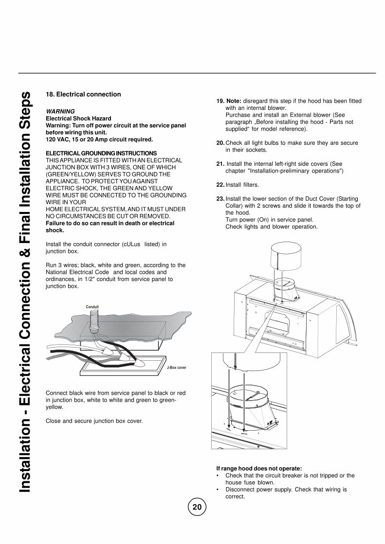
Use, Care, and Installation Guide Model number: Numéro de modèle: ____________________________________ Número de modelo: Serial number: Numéro de série: _____________________________________ Número de serie: Date of Purchase: Date d’achat: _____________________________________ Fecha de compra: Sales Dealer: Détaillant: _____________________________________ Distribuidor: LI2ZRA - DEC06.0101 READ AND SAVE THESE INSTRUCTIONS Guide d’utilisation, d’entretien et d’installation Guía de instalación, uso y mantenimiento LISEZ CES INSTRUCTIONS ET CONSERVEZ-LES LEA Y GUARDE ESTAS INSTRUCCIONES Padova CPA - E42ASX CPA - E48ASX CPA - E54ASX www.zephyronline.com
Transcript

Use, C

are

, an

d In

sta

llati

on

Gu

ide

Model number:

Numéro de modèle: ____________________________________

Número de modelo:

Serial number:Numéro de série: _____________________________________

Número de serie:

Date of Purchase:Date d’achat: _____________________________________

Fecha de compra:

Sales Dealer:Détaillant: _____________________________________

Distribuidor:

LI2ZRA - DEC06.0101

READ AND SAVE THESE INSTRUCTIONS

Gu

ide

d’u

tili

sa

tio

n,

d’e

ntr

eti

en

et

d’i

ns

tall

ati

on

Gu

ía d

e i

ns

tala

ció

n,

us

o y

ma

nte

nim

ien

to

LISEZ CES INSTRUCTIONS ET CONSERVEZ-LES

LEA Y GUARDE ESTAS INSTRUCCIONES

PadovaCPA - E42ASXCPA - E48ASXCPA - E54ASX

www.zephyronline.com

2

PLEASE READ ENTIRE INSTRUCTIONS BEFORE PROCEEDING.

INSTALLATION MUST COMPLY WITH ALL LOCAL CODES.

IMPORTANT: Save these Instructions for the Local Electrical Inspector’s use.

INSTALLER: Please leave these Instructions with this unit for the owner.

OWNER: Please retain these instructions for future reference.

Safety Warning: Turn off power circuit at service panel and lock out panel, before wiring this appliance.

Requirement: 120 V AC, 60 Hz. 15 or 20 A Branch Circuit

APPROVED FOR RESIDENTIAL APPLIANCESFOR RESIDENTIAL USE ONLY

READ AND SAVE THESE INSTRUCTIONS

English page 2

French page 28

Spanish page 56

3

www.zephyronline.com

Tab

le o

f C

on

ten

ts

Important Safety Notice .................................................................... 5

Electrical & Installation Requirements ............................................ 6

Electrical requirements .............................................................. 6

Before installing the hood ........................................................... 6

List of Materials ................................................................................. 7

Parts supplied ............................................................................ 7

Parts not supplied ...................................................................... 7

Dimensions and Clearances ............................................................. 8

Ducting Options and Examples ........................................................ 9

Venting methods ........................................................................ 9

Preparation ................................................................................ 9

Installation - Ductwork Calculation Sheet ..................................... 10

Installation - Preliminary Operations ............................................. 11

Installation - Internal Blower ..................................................... 12-13

Top discharge (Vertical discharge) ............................................ 12

Rear discharge (Horizontal discharge) ...................................... 12

Internal blower installation ........................................................ 13

Installation - External Blower Preparation ............................... 14-15

Vertical discharge .................................................................... 14

Horizontal discharge ................................................................ 14

External blower electrical connection-Preliminary operations .... 15

Installation - Front Panel ................................................................ 16

Installation ....................................................................................... 17

Installing the hood onto the wall ............................................... 17

4

Installation - Installing the Duct Covers ......................................... 18

Installation - Hanging the Hood onto the Wall .............................. 19

Installation - Electrical Connection & Final Installation Steps ..... 20

Electrical connection ................................................................ 20

Description of the Hood .................................................................. 21

Features & Controls - Touch Controls & Features ........................ 22

Description of control panel ...................................................... 22

Features & Controls - Baffle Filters Change Indicator ................. 23

Maintenance ............................................................................... 24-25

Cleaning ................................................................................... 24

Baffle Filter ............................................................................... 24

Replacing the halogen light bulb ............................................... 24

Replacing the mood lighting bulb .............................................. 25

Trouble Shooting ............................................................................. 26

List of Parts and Accessories .......................................................... 27

Tab

le o

f C

on

ten

ts

5

www.zephyronline.com

Imp

ort

an

t S

afe

ty N

oti

ceCAUTION

FOR GENERAL VENTILATING USE ONLY. DO NOT USE TO EXHAUST HAZARDOUS OR EXPLOSIVE MATERIALS ORVAPORS.

WARNING

TO REDUCE THE RISK OF FIRE, ELECTRIC SHOCK, OR INJURY TO PERSONS, OBSERVE THE FOLLOWING:A. Use this unit only in the manner intended by the manufacturer. If you have questions, contact the manufacturer.B. Before servicing or cleaning the unit, switch power off at service panel and lock service panel disconnecting means

to prevent power from being switched on accidentally. When the service disconnecting means cannot be locked,securely fasten a prominent warning device, such as a tag, to the service panel.

C. Installation Work and Electrical Wiring Must Be Done By Qualified Person(s) In Accordance With All Applicable Codes& Standards, Including Fire-rated Construction.

D. Sufficient air is needed for proper combustion and exhausting of gases through the flue (Chimney) of fuel burningequipment to prevent back- drafting. Follow the heating equipment manufacturers guideline and safety standardssuch as those published by the National Fire Protection Association (NFPA), the American Society for Heating,Refrigeration and Air Conditioning Engineers (ASHRAE), and the local code authorities.

E. When cutting or drilling into wall or ceiling, do not damage electrical wiring and other hidden utilities.F. Ducted systems must always be vented to the outdoors.

CAUTIONTo reduce risk of fire and to properly exhaust air, be sure to duct air outside - do not vent exhaust air into spaceswithin walls, ceilings, attics, crawl spaces, or garages.

WARNINGTO REDUCE THE RISK OF FIRE, USE ONLY METAL DUCT WORK.

Install this hood in accordance with all requirements specified.

WARNINGTo Reduce The Risk Of Fire Or Electric Shock, Do Not Use This Hood With Any External Solid State Speed ControlDevice.

WARNINGTO REDUCE THE RISK OF A RANGE TOP GREASE FIRE.a) Never leave surface units unattended at high settings. Boilovers cause smoking and greasy spillovers that may

ignite. Heat oils slowly on low or medium settings.

b) Always turn hood ON when cooking at high heat or when flambeing food (I.e. Crepes Suzette, Cherries Jubilee,

Peppercorn Beef Flambe’).

c) Clean ventilating fans frequently. Grease should not be allowed to accumulate on fan or filter.

d) Use proper pan size. Always use cookware appropriate for the size of the surface element.

WARNING

TO REDUCE THE RISK OF INJURY TO PERSONS, IN THE EVENT OF A RANGE TOP GREASE FIRE, OBSERVE THEFOLLOWING:a) SMOTHER FLAMES with a close-fitting lid, cookie sheet, or other metal tray, then turn off the gas burner or the electric

element. BE CAREFUL TO PREVENT BURNS. If the flames do not go out immediately, EVACUATE AND CALL THEFIRE DEPARTMENT.

b) NEVER PICK UP A FLAMING PAN - you may be burned.c) DO NOT USE WATER, including wet dishcloths or towels - a violent steam explosion will result.d) Use an extinguisher ONLY if:

1) You know you have a class ABC extinguisher, and you already know how to operate it.2) The fire is small and contained in the area where it started.3) The fire department is being called.4) You can fight the fire with your back to an exit.

OPERATION

a. Always leave safety grills and filters in place. Without these components, operating blowers could catch onto hair,

fingers and loose clothing.

The manufacturer declines all responsibility in the event of failure to observe the instructions given here for installation,maintenance and suitable use of the product. The manufacturer further declines all responsibility for injury due tonegligence and the warranty of the unit automatically expires due to improper maintenance.* NOTE: Please check our website for revisions before doing any custom work.

READ AND SAVE THESE INSTRUCTIONS

6

Ele

ctr

ical &

In

sta

llati

on

Req

uir

em

en

ts ELECTRICAL REQUIREMENTS

IMPORTANT

Observe all governing codes and ordinances.

It is the customer’s responsibility:

To contact a qualified electrical installer.

To assure that the electrical installation is adequate and in conformance with National Electrical Code, ANSI/NFPA 70 —

latest edition*, or CSA Standards C22.1-94, Canadian Electrical Code, Part 1 and C22.2 No.0-M91 - latest edition** and all

local codes and ordinances.

If codes permit and a separate ground wire is used, it is recommended that a qualified electrician determine that the

ground path is adequate.

Do not ground to a gas pipe.

Check with a qualified electrician if you are not sure range hood is properly grounded.

Do not have a fuse in the neutral or ground circuit.

IMPORTANT

Save Installation Instructions for electrical inspector’s use.

The range hood must be connected with copper wire only.

The range hood should be connected directly to the fused disconnect (Or circuit breaker) box through metal electrical

conduit.

Wire sizes must conform to the requirements of the National Electrical Code ANSI/NFPA 70 — latest edition*, or CSA

Standards C22.1-94, Canadian Electrical Code Part 1 and C22.2 No. 0-M91 - latest edition** and all local codes and

ordinances.

A U.L.- or C.S.A.-listed conduit connector must be provided at each end of the power supply conduit (At the range hood and

at the junction box).

Copies of the standards listed may be obtained from:

* National Fire Protection Association Batterymarch Park Quincy, Massachusetts 02269

** CSA International 8501 East Pleasant Valley Road Cleveland, Ohio 44131-5575

BEFORE INSTALLING THE HOOD

1. For the most efficient air flow exhaust, use a straight run or as few elbows as possible.

CAUTION: Vent unit to outside of building, only.

2. At least 3 people are necessary for installation.

3. The hood is fitted with Screws and Drywall Anchors suitable for most surfaces, consult a Qualified Installer, check if they

perfectly fit with your cabinet/wall.

4. Use flex ducting CulUS approved.

5. COLD WEATHER installations should have an additional backdraft damper installed to minimize backward cold air flow

and a thermal break to minimize conduction of outside temperatures as part of the ductwork. The damper should be on

the cold air side of the thermal break.

The break should be as close as possible to where the ducting enters the heated portion of the house.

6. Make up air: Local building codes may require the use of Make-Up Air Systems when using Ducted Ventilation Systems

greater than specified CFM of air movement.

The specified CFM varies from locale to locale. Consult your HVAC professional for specific requirements in your area.

WARNING! Don't add to the hood weights of over 10 kg (20.4 Lbs.).

7

www.zephyronline.com

Lis

t o

f M

ate

rialsPARTS SUPPLIED

• Hood body, with stainless steel baffle filter and halogen light bulbs and incandescent lamp already installed

• Two telescopic duct covers and support bracket

• Hardware Packet:

- 24x53 T1T2 "L" Male monkey spanner (1 piece)

- 3.5X9.5 screws to fix the internal blower (4 pieces)

- 3.5X9.5 screws to fix the duct cover (4 pieces)

- 3.5X9.5 screws to fix the 8" collar plastic round transition duct cover (4 pieces)

- 4x8 screws to fix the external blower wiring box (4 pieces)

- M4 nut for the grounding screw to connect the grounding screw to the external blower (3 pieces)

- toothed washer to connect the grounding screw to the external blower (3 pieces)

• Wall mounting brackets (1 piece)

• 8" Collar (1 piece)

• Plastic round transition with damper (1 piece)

• Cover round transition (1 piece)

• Rectangular transition air discharge + flange

• External blower wiring box with wires

• Template (1 piece)

• Use, Care and Installation Guide

• Warranty

PARTS NOT SUPPLIED

• Duct, conduit and all tools required for installation.

• Internal blowerTo be used only in case of Internal blower installation.

• External blowerTo be used only in case of External blower installation.

• Front panel.

CAUTION

To reduce the risk of fire and electric shock, install this rangehood only with integral blowers mod. EBI-600B

manufactured by ZEPHYR or with external blowers mod. CBE-1000, manufactured by ZEPHYR.

And with front panels mod. CPC-0012 (42" SS); mod. CPC-0112 (42" Brass); mod. CPC-0018 (48" SS); mod. CPC-

0118 (48" Brass); mod. CPC-0015 (54" SS); mod. CPC-0115 (54" Brass).

WARNING

To Reduce The Risk Of Fire, Electric Shock, And Injury To Persons, this rangehood Must Be Installed With Front

Panels That Are Marked (on their cartons) To Indicate The Suitability With This Model. Other Front Panels Cannot

Be Substituted.

8

Dim

ensi

on

s an

d C

lear

ance

s

Only for version with top discharge feature:* Hood with external motor: Over this measurement a hole may be made on the rear section for the passage of the discharge pipe for

connection to the external motor. Consult the template for the passage of pipes under this measurement.** Hood with external motor: Above this measurement a hole may be made on the rear panel for the outward passage of the

discharge pipe. Consult the template for the passage of pipes under this measurement.

9

www.zephyronline.com

Du

cti

ng

Op

tio

ns a

nd

Exam

ple

sClosely follow the instructions set out in this manual.

All responsibility, for any eventual inconveniences, damages or fires caused by not complying with the instructions in

this manual, is declined.

VENTING METHODS

This range hood is designed to exhaust fumes and vapours towards the outside and is ready to be fitted with an internal

blower and for discharge towards the top side (Vertical discharge).

This range hood can be set for an External Blower and /or to discharge towards the rear side (Horizontal discharge).

Before installation choose type of motor an discharge direction.

Consult paragraph "Dimensions and Clearances" and "Installation - Ductwork Calculation Sheet" for further

informations.

Minimum Duct Size : 8" Round Pipe or 3 1/4 ” x 10” Rect. Pipe (Rect. Pipe can be used for Internal blower installation

only)

PREPARATION

Do not cut a joist or stud unless absolutely necessary. If a joist or stud must be cut, then a supporting frame must be

constructed.

Fitting material is provided to secure the hood to most types of walls/ceilings.

However, a qualified technician must verify suitability of the materials in accordance with the type of wall/ceiling.

Before making cutouts, make sure there is proper clearance within the ceiling or wall for exhaust vent.

Hood installation height above cooktop is the users preference. The lower the hood is above the cooktop, the more

efficient the capturing of cooking odors, grease and smoke.

The hood shall be installed at 28" minimum above the countertop (Distance must be taken from the bottom side ofthe hanging rail of the front panel).Check your ceiling height and the hood height maximum before you select your hood.

Refer to the following table for the weights:

DESCRIPTION MODEL

HOOD ONLY

INTERNAL BLOWER

42"

98.5 lbs.

48" 54"

9.5 lbs.

105 lbs.

9.5 lbs.

112 lbs.

9.5 lbs.

10

Insta

llati

on

-

Du

ctw

ork

Calc

ula

tio

n S

heet

3 1/4 ” x 10”

Rect.,

straight

6 ” Round,,

straight

7", 8”

Round,,

straight

3 1/4 ” x 10”

Rect.90°

elbow

3 1/4 ” x 10”

Rect.45°

elbow

3 1/4 ” x 10”

Rect.90°

flat elbow

3 1/4 ” x 10”

Rect.

wall cap

with damper

3 1/4 ” x 10”

Rect.to

6 ” round

transition

3 1/4 ” x 10”

Rect.to

6 ” round

transition

90° elbow

6 ” Round,,

90° elbow

6 ” Round,,

45°elbow

1 Ft. x ( ) =

1 Ft. x ( ) =

1 Ft. x ( ) =

15 Ft. x ( ) =

9 Ft. x ( ) =

24 Ft. x ( ) =

30 Ft. x ( ) =

5 Ft. x ( ) =

15 Ft. x ( ) =

15 Ft. x ( ) =

9 Ft. x ( ) =

Ft.

Ft.

Ft.

Ft.

Ft.

Ft.

Ft.

Ft.

Ft.

Ft.

Ft.

6" Round

wall cap

with damper

6” Round,

roof cap

6” Round to

3 1/4 ” x 10”

rect.

transition

6” Round to

3 1/4 ” x 10”

rect.

transition

90° elbow

7", 8" round

90° elbow

7", 8" round

45° elbow

7", 8" Round

wall cap

with damper

7", 8"

Round,

roof cap

7” Round to

3 1/4 ” x 10”

rect.

transition

6” Round to

3 1/4 ” x 10”

rect.

transition

90° elbow

30 Ft. x ( ) =

30 Ft. x ( ) =

1 Ft. x ( ) =

16 Ft. x ( ) =

15 Ft. x ( ) =

9 Ft. x ( ) =

30 Ft. x ( ) =

30 Ft. x ( ) =

8 Ft. x ( ) =

15 Ft. x ( ) =

Ft.

Ft.

Ft.

Ft.

Ft.

Ft.

Ft.

Ft.

Ft.

Ft.

Duct pieces Equivalent number

lenght x used = Total

Duct pieces Equivalent number

lenght x used = Total

Subtotal column 2 =

Subtotal column 2 =

Total ductwork =Subtotal column 1 =

Maximum Duct Length: For satisfactory air movement, the

total duct length should not exceed 100 equivalent feet.

Note: Do not use smaller size duct than specified.

11

www.zephyronline.com

Insta

llati

on

- P

relim

inary

Op

era

tio

nsAttention! The installation requires several steps

where is asked to temporarily remove someparticulars and screws, We recommend to recordand keep all of these components in a safe placeready to be used as required.• Remove stainless mesh filters (See relative

paragraph on Maintenance section of this manual).

• Release the 4 per side threaded knobs and remove

the internal left-right side covers.

• Unscrew the 4 screws that fix the cover to the

Junction box, to access mains connection area.

12

Insta

llati

on

- In

tern

al B

low

er Note: for External blower installation disregard the

instruction in this page and step ahead on page 14.

TOP DISCHARGE(Vertical discharge)

The hood is ready to be used for vertical discharge,

proceed to install the internal blower (See next page).

REAR DISCHARGE(Horizontal discharge)

• Remove the internal blower support (Top side)

unscrewing the 4 fixing screws.

• From the inside of the hood, rear side remove

cover/rectangular transition support from the range

hood body unscrewing the 4 fixing screws.

• Install the motor support to the body of the hood

(Rear side) with 4 screws in place of the rear cover

previously removed.

Note! Lip of motor support must be towards the

inside of the hood in order for screw holes to line

up.

• Close, from the inside of the hood, the top hole with

the cover/rectangular transition support and fix it to

the body of the hood with 4 screws (Screws holes

disposition is obliged!).

13

www.zephyronline.com

INTERNAL BLOWER INSTALLATION

• Fit the blower inside the hood.

• Install the blower to the support with 4 screws

(Provided), check that the rectangular outlet of the

blower matches with the rectangular slot of thesupport.

Note: The 4 fixing screws must be screwed in from

the outside of the hood (See photo below).

• Connect the blower to the range hood.

Insta

llati

on

- In

tern

al B

low

er

14

• Install the supplied round transition collar to the

previously installed cover/round transition support

plate from inside the hood. Align and attach with 2

screws securely.

Horizontal discharge

• From the inside of the hood, remove (rear side) thecover/rectangular transition support unscrewing the 4screws that fix it to the body of the range hood.

• Remove the cover/rectangular transition support plate

from inside the hood on back panel.

• Install the supplied cover/round transition support

plate using the previously removed 4 screws to the

same location of the removed internal blower support

plate. Align the screw and attach securely.

• Remove the round knock out.

Insta

llati

on

- E

xte

rnal B

low

er

Pre

para

tio

n Note: for internal blower installation, disregard the

instruction on this next page and consult the instructionon the previous pages (See pages 12-13).Note 2: Refer to the CBE-1000 manual for instructions on

mounting the external blower to a roof or exterior wall.

The manual is available on our website and is included

in the external blower packaging.

WARNING!Do not use the rectangular transition for Externalblower installation, the use of this transition is , in thiscase, forbidden!Use only a 8" Round Pipe! See Installation step 9 onpage 17 for further informations.

Vertical discharge

• Remove the cover/rectangular transition support plate

from inside the hood on upper panel.

Locate and remove 4 screws that attach it.

• Install the supplied round transition collar to the

previously installed blower support plate. Align the

screw holes and attach securely.

15

www.zephyronline.com

• Install the supplied round transition collar to the

previously installed cover/round transition support

plate. Align and attach with 2 screws securely.

EXTERNAL BLOWER ELECTRICAL CONNECTION- PRELIMINARY OPERATIONS

Installing the external blower junction box

• Remove the electrical knock out on the upper panel.

See diagram below.

• Connect the supplied 9 pin male molex plug from the

external blower wiring to the 9 pin female molex plug on

the control board housing. Route wire end through

hood and terminate in external blower junction box. See

diagram below.

Insta

llati

on

- E

xte

rnal B

low

er

Pre

para

tio

n

EXT.BLOWER

REMOTE FAN UNIT JUNCTION BOX

BLACK (HIGH)

RED (LOW)

WHITE (COMMON)

BLUE (MED)

Y/G (GROUND)

HOOD

= CONNECTION WIRE TO WIRE

BLACK

RED

WHITE

BLUE

Y/G

CONDUITWIRES

RED (LOW)

Y/G (GROUND)

BLACK (HIGH)

BLUE (MED)

WHITE (COMMON)

• Connect the eyelet terminal of the yellow/green conductor

to the grounding screw located inside the hood.

• Remove the cover of the junction box.

Run electrical conduit to junction box and secure with

listed conduit fitting. Carry out the electrical connections.

Reinstall the junction box cover.

Upper outlet(Vertical discharge)

Knock-outJunction box(Mains connection)

Knock-out(External Blowerconnection)

• Install the external blower junction box with 4 screws.

16

• To attach front panel to hood body, align the 8 threaded studs through the front bodies corresponding holes.

Use 8 wing nuts to attach and secure. See diagrams below

2

3

1

4

6

5

8

7

12

34

5

6

7

8

3

4

Insta

llati

on

- F

ron

t P

an

el

NOTE: The front panel is not supplied with the range hood and must be purchased separately.

x 8

17

www.zephyronline.com

Insta

llati

onINSTALLING THE HOOD ONTO THE WALL

1. Disconnect and move freestanding or slide-in range

from cabinet opening to provide easier access to

rear wall. Use a thick, protective covering over

countertop, cooktop or range to protect from damage

and debris. Select a flat surface for assembling the

unit. Cover that surface with a protective covering

and place all canopy hood parts and hardware in it.

2. Mark the centerline on the wall/ceiling where the

canopy hood will be installed.

Note: Draw the line on ceiling if is intended to install

the supplied Duct Covers.

3. Select a mounting height comfortable for the user

and mark on wall (minimum 28").

4. Tape template, matching center-line and hood

bottom as shown in Figure below.

5. Place the support bracket on the template to coinci-

de with the outlined rectangle, mark center of all

fastener location (Horizontal rear discharge requires

additional marks for venting passage). Remove

template.

Support bracket

Centerline

CL

Fastener locations

6. Mark wall with horizontal line 1" above highest and 1"

below lowest fastener location. Using a carpenter’s

level.

7. Find studs behind drywall by tapping wall or using a

stud finder. Mark the center of the studs with a

vertical line to the right and left of the marked

fastener location.

8. Note: All fastener locations must attach to studs and/

or blocking, otherwise proceed as follows:

Cutout drywall along marked lines. Install wood

blocking between studs and make sure it is flush

with existing stud front. Make sure all mounting

screws will anchor to added studs. Replace drywall

and refinish.

9. Determine and make all necessary cuts in the wall

for the vent system. Install the vent system before

the canopy hood. See „Venting methods“ and

„Dimensions and clearance“ paragraphs.

IMPORTANT - for External blower installationONLY: Run 10” round duct work from the external

blower to the ceiling. Before the duct work passes

through the ceiling bracket, use a 10” to 8” transition

adapter (included with external blower) and run 8”

duct work to the opening on the hood. The 8” duct

work run should not exceed 60” in length.

10. Determine the required height for the conduit and

cut a 1-1/4" (3.2 cm) hole at this location.

Run wires through hole according the National

Electrical Code or CSA Standards and local codes

and ordinances.

Note: External blower installation requires and

additional hole/conduit.

There must be enough power supply cable from the

fused disconnect (Or circuit breaker) box to make

the connection in the hood’s Junction box/es.

Use caulking to seal all openings.

Do Not turn on power until installation is completed.

11.Remark center line and hood bottom on same

location as before and tape template on wall as in

step 4 above.

12.Mount the lower support bracket with wood screws

and washers (Supplied in mounting hardware kit)

on locations marked on template, then remove

template.

CL

Framing behind drywall

wood blockingsecured to studsand located behinddrywall

18

13. Optional duct cover installation:

a. Remove the support bracket from the Duct Cover

assembly and attach it to the ceiling with 2 drywall

anchors and screws

Note: The printed index on the bracket must match

the center line previously drawn (See installation

step 2).

Conduit

Duct

Positionreference

Positionreference

CenterLine

Duct coversupport barcket

Insta

llati

on

- In

sta

llin

g t

he D

uct

Co

vers

Unscrew the 4 screws that fix the section of the Duct

Cover (Starting collar) and release all parts.

Install the upper section to the support bracket with

2 screws.

Note: Check that joined seam is positioned towards

the back.

Note2: The lower section (Collar) of the duct cover

assembly must be installed at the end of the

installation with 2 screws.

SupportBracket

Uppersection

Lowersection(Collar)

19

www.zephyronline.com

Insta

llati

on

- H

an

gin

g t

he H

oo

d o

nto

th

e W

all14. For internal blower installation ONLY:

a. Horizontal (Rear) discharge:Install from the outside the 3 1/4 ” x 10” Rect.

transition on the outlet hole of the blower with 3

screws.

b. Vertical (Upper) discharge:Install from the outside the 8" plastic round

transition, with 4 screws. Install transition so that

little position adjustment are allowed.

Note: Seal with duct tape only when transition is

firmly attached to the range hood.

Do not use duct smaller than the transition, (seeinstallation step 9) for further instruction aboutduct to be used.

15. Hang hood on lower bracket.

WARNING

Excessive Weight Hazard - Use three or more peopleto move and install range hood. Failure to do so canresult in back or other injury.

16. Secure hood with screws and washers.

17. Connect the ducting to the transition. Seal with duct

tape.

Note: If Duct has been already fixed to transition

(See installation step 15b), install the transition to

the hood with 4 screws.

Do not use duct smaller than the transition, seeinstallation step 9 for further instruction aboutduct to be used.

Rear outlet(Horizontaldischarge)

Upper outlet(Vertical discharge)

Knock-out junction box (Mains connection)

Knock-out (External Blower connection)

Hanging bracketBottom securityscrews hole

Bottom securityscrews hole

Uppersecurityscrewhole

Uppersecurityscrewhole

Lowersupportbracket

CenterLine

Rectangulartransition

20

Insta

llati

on

- E

lectr

ical C

on

necti

on

& F

inal In

sta

llati

on

Ste

ps 18. Electrical connection

WARNING

Electrical Shock HazardWarning: Turn off power circuit at the service panelbefore wiring this unit.120 VAC, 15 or 20 Amp circuit required.

ELECTRICAL GROUNDING INSTRUCTIONSTHIS APPLIANCE IS FITTED WITH AN ELECTRICAL

JUNCTION BOX WITH 3 WIRES, ONE OF WHICH

(GREEN/YELLOW) SERVES TO GROUND THE

APPLIANCE. TO PROTECT YOU AGAINST

ELECTRIC SHOCK, THE GREEN AND YELLOW

WIRE MUST BE CONNECTED TO THE GROUNDING

WIRE IN YOUR

HOME ELECTRICAL SYSTEM, AND IT MUST UNDER

NO CIRCUMSTANCES BE CUT OR REMOVED.

Failure to do so can result in death or electricalshock.

Install the conduit connector (cULus listed) in

junction box.

Run 3 wires; black, white and green, according to the

National Electrical Code and local codes and

ordinances, in 1/2" conduit from service panel to

junction box.

J-Box cover

Conduit

Connect black wire from service panel to black or red

in junction box, white to white and green to green-

yellow.

Close and secure junction box cover.

19. Note: disregard this step if the hood has been fitted

with an internal blower.

Purchase and install an External blower (See

paragraph „Before installing the hood - Parts not

supplied“ for model reference).

20. Check all light bulbs to make sure they are secure

in their sockets.

21. Install the internal left-right side covers (See

chapter "Installation-preliminary operations")

22. Install filters.

23. Install the lower section of the Duct Cover (Starting

Collar) with 2 screws and slide it towards the top of

the hood.

Turn power (On) in service panel.

Check lights and blower operation.

If range hood does not operate:• Check that the circuit breaker is not tripped or the

house fuse blown.

• Disconnect power supply. Check that wiring is

correct.

21

www.zephyronline.com

Descri

pti

on

of

the H

oo

d1 Controls

2 Baffle filter

3 Halogen lamp

4 Incandescent ambient lamp

5 Hood body

6 Duct cover

6

2

23 3

4

1

5

22

Featu

res &

Co

ntr

ols

- T

ou

ch

Co

ntr

ols

& F

eatu

res Use the high suction speed in cases of concentrated kitchen vapors. It is recommended that the cooker hood suction is

switched on for 5 minutes prior to cooking and to leave in operation during cooking and for another 15 minutes after

terminating cooking.

Note: Hood retains last speed setting when aspiration switch is turned off.

Description of control panel:

1. Blower On/Off

By pressing ,the blower is switched On and Off.

2. Speed SelectionThe 3 speed levels are selected by pressing to decrease and to increase speed level.

The display indicates level selected.

3. Delay OffThis is used for programmed shut down of blower and lights 15 minutes after the function is activated.

Press once,a dot flashes in the lower right hand side of display indicating the function is on.The hood will completely shut down in 15 minutes.

4. Lights On/Off/Dim

Switch lights On and Off by pressing once.To dim lights,press and hold it in for 2 seconds.

5. Advance Display Functions

6. Mood Light On/OffThis switch turns the mood lights On and Off.Press IN to turn on,press again to turn OFF.

Filters Clean Reminder (Metal):

1 5

26

4

3

Blower ON/OFF Display (Speed Level, Delay Off Indicator, Filter Clean)

Adjust 3 Speed LevelsMood Light ON/OFF

Lights ON/OFF/Hold to Dim

15 Min Delay Off

23

www.zephyronline.com

Filter Clean Reminder (Standard Baffle Filters fitted):

A set of baffle filters are fitted by the factory. These Baffle Filters are intended to filter out residue from cooking. They

need not be replaced on a regular basis but are required to be kept clean. The Filter Clean Reminder function in

the microprocessor will automatically indicate by a flashing when the metal filters need to be cleaned after

every 30 hrs. of use. Filters can be cleaned by hand with non-abrasive soap or in a dishwasher.

Filter Clean Reminder:

When flashes on display, the baffle filters installed

are required to be cleaned.

This will occur after every 30 hours of use.

Re-setting Function:

Reset the Filter Clean Reminder timer when filters are

cleaned and re-installed (with hood off).

Press and hold for approx. 5 seconds, the display will

appear; hold for approximately 5 seconds until on

display disappears .The Filter Clean Reminder function is now re-set and a

new 30 hours elapse cycle is initiated.

Clean Filters

display <A> flashes

To Reset

display from <A> to < >hold 5 secs.

Featu

res &

Co

ntr

ols

- T

ou

ch

Co

ntr

ols

& F

eatu

res

24

Main

ten

an

ce

BAFFLE FILTER

This must be cleaned once a month using non abrasi-

ve detergents, either by hand or in the dish-washer,

which must be set to a low temperature and a short

cycle.

When washed in a dish-washer, the baffle filter may

discolor slightly, but this does not affect its filtering

capacity.

To remove the baffle filter, pull (a) the handle and extract

the filters (b).

REPLACING THE HALOGEN LIGHT BULB:

WARNING

Disconnect the hood from electricity and be sure thelights are cool.

If new lights do not operate, make sure the light bulb is

inserted correctly before calling service.

• Remove bulb by pressing both ends of the metal

retaining clip together, the light socket will now

protude from the hood allowing you to remove thebulb.(Be careful when releasing retain clip as it is under

pressure to hold it in place)

• Replacement halogen bulbs are available at most

stores which sell light bulbs. Purchase type GU-10,

120V, 50W. Follow package directions.

• Reinstall the metal retaining.

ATTENTION!

Prior to any maintenance operation ensure that the cooker hood is disconnected from the power supply.

CLEANING

The cooker hood should be cleaned regularly internally and externally.

Use a cloth moistened with a neutral liquid detergents. Avoid abrasive detergents.

Warning:Failure to carry out the basic cleaning recommendations of the cooker hood and replacement of the filters may cause fire

risks.

Therefore, we recommend oserving these instructions.

a

a

b

b

metalretaining

25

www.zephyronline.com

Main

ten

an

ceREPLACING THE MOOD LIGHTING BULB:

To replace mood lighting bulb, remove baffle filter from

hood.

To access lamp area, remove the two threaded knobs

that fix the cover.

Unscrew mood lighting bulb counter-clockwise and

replace with a standard max. 40W, type T10, 125V-130V

medium base bulb.

26

Tro

ub

le S

ho

oti

ng

After installation, the

unit doesn’t work?

Light works, but motor

is not turning.

The unit is vibrating.

The motor is working,

but the lights are not.

The hood is not venting

out properly.

Metal filter is vibrating.

1. The power source is not turned ON.

2. The power line and the cable locking

connector is not connecting properly.

3. The switch board and control board

wirings are disconnected.

4. The switch board or control board is

defective.

1. The motor is defective, possible

seized.

2. The thermally protected system

detects if the motor is too hot to

operate and shuts the motor down.

3. Damaged condenser.

1. The motor is not secure in place.

2. Damaged blower wheel.

3. The hood is not secured in place.

1. Defective halogen bulb.

2. The light bulb is loose.

1. The hood might be hanging to high

from the cook top.

2. The wind from the opened windows

or opened doors in the surrounding

area are affecting the ventilation of

the hood.

3. Blocking in the duct opening or

ductwork.

4. The direction of duct opening is

against the wind.

5. Using the wrong size of ducting.

1. Metal filter is loose.

Issue Cause What to do

1. Make sure the circuit breaker and the

unit’s power is ON.

2. Check the power connection with the

unit is connected properly.

3. Make sure the wirings between the

switch board and control board are

connected properly.

4. Change the switch board or control

board.

1. Change the motor.

2. The motor will function properly after

the thermally protected system cool

down.

3. Change the condenser.

1. Tighten the motor in place.

2. Change the blower wheel.

3. Check the installation of the hood.

1. Change the halogen bulb.

2. Tighten the light bulb.

1. Adjust the distance between the cook

top and the bottom of the hood within

24” and 32” range.

2. Close all the windows and doors to

eliminate the outside wind flow.

3. Remove all the blockage from the duct

work or duct opening.

4. Adjust the duct opening direction.

5. Change the ducting to at least 8” or

higher.

1. Change the metal filter.

27

www.zephyronline.com

Lis

t o

f P

art

s a

nd

Accesso

ries

Part Description Part#

Internal Blower 600 CFM

External Blower 1000 CFM

Halogen Bulb, 120V 50 W

Filter Baffle

Z0B0020S

EBI-600B

CBE-1000

Front Panel 42" SS CPC-0012

Front Panel 42" Brass CPC-0112

Front Panel 48" SS CPC-0018

Front Panel 48" Brass CPC-0118

Front Panel 54" SS CPC-0015

Front Panel 54" Brass CPC-0115

50210002

Doluflex 6pc. Blank, 42" CDO-0042

Doluflex 6pc. Blank, 48" CDO-0048

Doluflex 6pc. Blank, 54" CDO-0054

Veneer, 6pc. Copper, 42" CDO-0142

Veneer, 6pc. Copper, 48" CDO-0148

Veneer, 6pc. Copper, 54" CDO-0154

Veneer, 6pc. Stainless, 42" CDO-0242

Veneer, 6pc. Stainless, 48" CDO-0248

Veneer, 6pc. Stainless, 54" CDO-0254

Part Description Part#


Recommended