21B1-E-0056 Long Term Record Data Saving 3years in Compact Flash (In case of using 512MB Compact Flash) Saved Data playback Saved data in Memory card can be easily called out and played back on display Math and totalization These functions are available as standard. Communication RS485, MODBUS RTU protocol is available. (option) Ethernet (10Base-T) is available. (option) Screen saver Period of non-operation exceeds the setting value of parameter, recorder turns off the backlight of LCD. PC support softwares (Data Viewer/Parameter Loader) Supplied in a CD-ROM as a part of standard accessory Compact size 160 (W) X 144 (H) X 185 (D) mm (Panel mount)1.5 kg compact size 9-point recording and 18-point max. recording 12 types of thermocouples, 5 types of resistance bulbs and voltage/current input are available Paperless Recorder Type:PHL
Transcript
21B1-E-0056
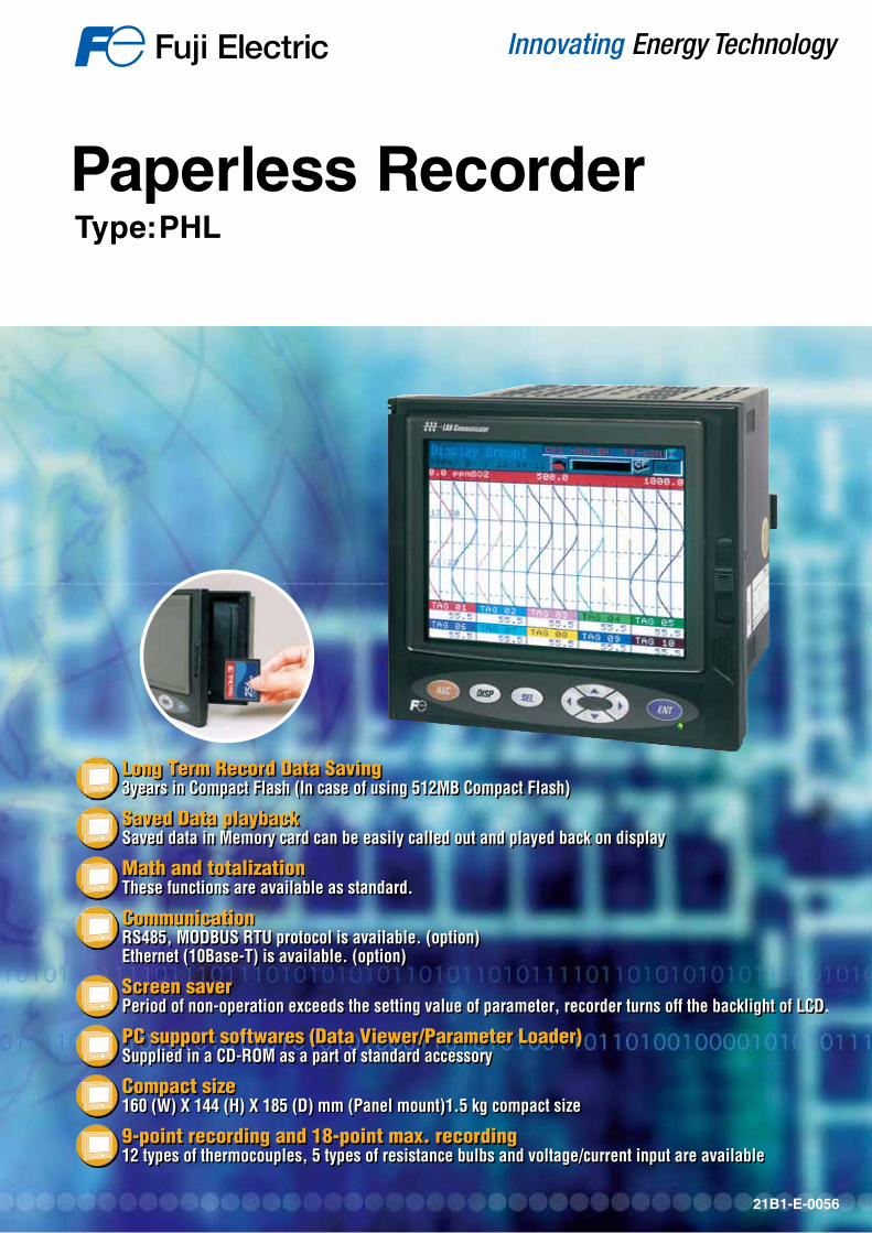
Long Term Record Data Saving3years in Compact Flash (In case of using 512MB Compact Flash)
Saved Data playback Saved data in Memory card can be easily called out and played back on display
Math and totalizationThese functions are available as standard.
Communication RS485, MODBUS RTU protocol is available. (option)Ethernet (10Base-T) is available. (option)
Screen saver Period of non-operation exceeds the setting value of parameter, recorder turns off the backlight of LCD.
PC support softwares (Data Viewer/Parameter Loader)Supplied in a CD-ROM as a part of standard accessory
Compact size 160 (W) X 144 (H) X 185 (D) mm (Panel mount)1.5 kg compact size
9-point recording and 18-point max. recording12 types of thermocouples, 5 types of resistance bulbs and voltage/current input are available
Paperless RecorderType:PHL
Calculation function offered as standardSubtractionDifference between the values of each channel can be calculated.
F value calculationExtinction rate of bacteria by heat sterilization can be calculated per channel according to the measured temperature.
TotalizationMeasured value of each channel can be totalized.Reference time can be selected from day, hour, minute and second.
Square root extractionSquare root extraction of the input value of each channel can be performed.
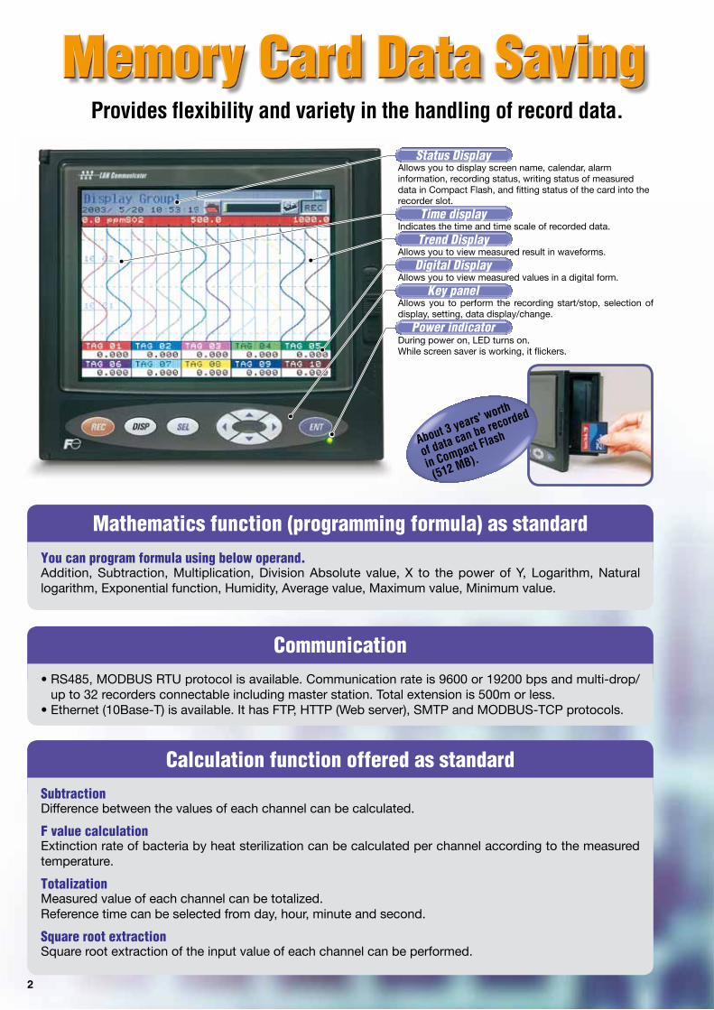
Provides flexibility and variety in the handling of record data.
About 3 years' worth
of data can be recorded
in Compact Flash
(512 MB).
Mathematics function (programming formula) as standard
You can program formula using below operand.Addition, Subtraction, Multiplication, Division Absolute value, X to the power of Y, Logarithm, Natural logarithm, Exponential function, Humidity, Average value, Maximum value, Minimum value.
Communication • RS485, MODBUS RTU protocol is available. Communication rate is 9600 or 19200 bps and multi-drop/
up to 32 recorders connectable including master station. Total extension is 500m or less. • Ethernet (10Base-T) is available. It has FTP, HTTP (Web server), SMTP and MODBUS-TCP protocols.
2
StatusDisplayAllows you to display screen name, calendar, alarm information, recording status, writing status of measured data in Compact Flash, and fitting status of the card into the recorder slot.
TimedisplayIndicates the time and time scale of recorded data.
TrendDisplayAllows you to view measured result in waveforms.
DigitalDisplay Allows you to view measured values in a digital form.
Keypanel Allows you to perform the recording start/stop, selection of display, setting, data display/change.
PowerindicatorDuring power on, LED turns on.While screen saver is working, it flickers.
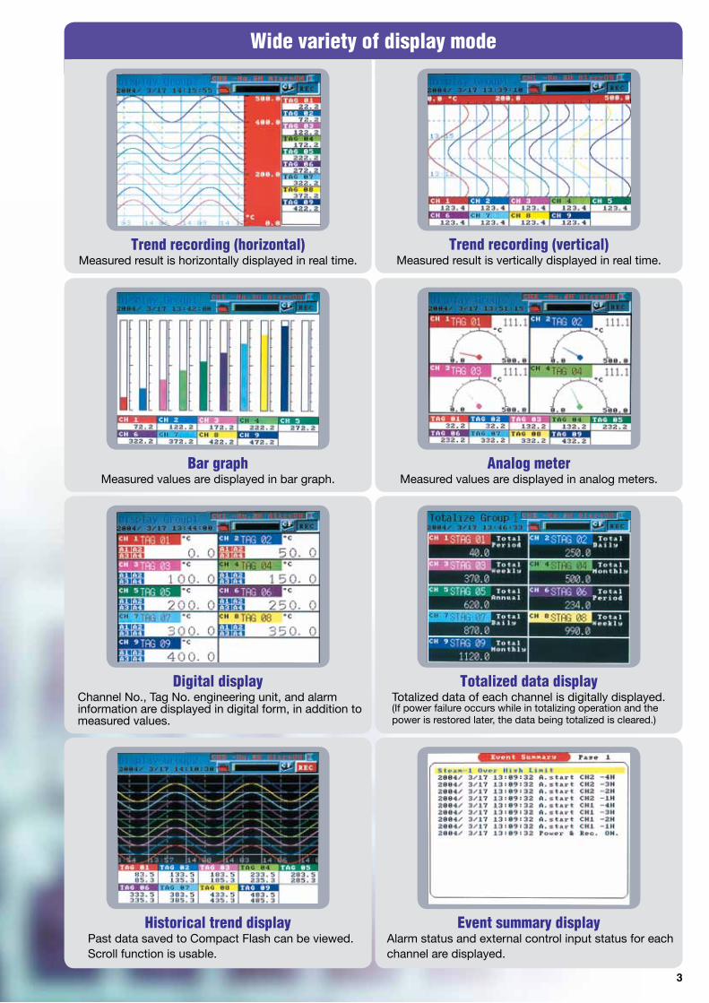
Wide variety of display mode
Trend recording (horizontal)Measured result is horizontally displayed in real time.
Trend recording (vertical)Measured result is vertically displayed in real time.
Bar graphMeasured values are displayed in bar graph.
Analog meterMeasured values are displayed in analog meters.
Digital displayChannel No., Tag No. engineering unit, and alarm information are displayed in digital form, in addition to measured values.
Totalized data displayTotalized data of each channel is digitally displayed.(If power failure occurs while in totalizing operation and the power is restored later, the data being totalized is cleared.)
Historical trend displayPast data saved to Compact Flash can be viewed. Scroll function is usable.
Event summary displayAlarm status and external control input status for each channel are displayed.
3
4
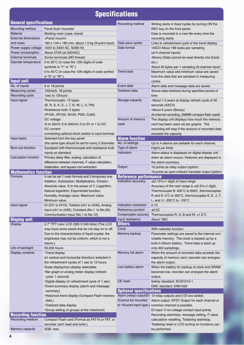
SpecificationsGeneral specifications
Input unit
Alarm function
Reference performance
Others
Optional specifications
Mathematics function
Display unit
Recording function
Mounting methodMaterialExternal dimensionsand massPower supply voltagePower consumptionExternal terminalsOperate temperature
No. of inputs Measuring cyclesRecording cycleInput signal
Alarm (relay) output/DI(Cannot be mountedto 18-point input type.)
Panel flush mountedMolding resin (case, bezel)<Panel mount>160 x 144 x 185 mm, about 1.5 kg (9-point input)100V to 240V AC, 50/60 HzAbout 47VA (at 200VAC)Screw terminals (M3 thread)0 to 50˚C (in case the 12th digits of code symbols is “Y” or “R”.)0 to 40˚C (in case the 12th digits of code symbol is “E” or “W”.)
9 or 18 points 100ms/9, 18 points1sec to 12hoursThermocouple: 12 types (B, R, S, K, E, J, T, N, W, L, U, PN)Resistance bulb: 5 types(Pt100, JPt100, Ni100, Pt50, Cu50)DC voltage:(0 to 50mV, 0 to 500mV, 0 to 5V or 1 to 5V)DC current:(connecting optional shunt resistor to input terminal)Selected from the key panel (the same type should be set for every 2 channels)Equipped with thermocouple and resistance bulb inputs as standard.Primary delay filter, scaling, calculation of difference between channels, F value calculation, totalization, and square root extraction
It can be set 1 main formula and 3 temporary one.Addition, Subtraction, Multiplication, Division Absolute value, X to the power of Y, Logarithm, Natural logarithm, Exponential function, Humidity, Average value, Maximum value, Minimum value.DI (DI1 to DI10), Totalize (ch1 to ch30), Analog input (ch1 to ch30), Constant (No.1 to No.20), Communication input (No.1 to No.12)
5.7" TFT color LCD (320 X 240 dots) (The LCD may have some pixels that do not stay on or off.Due to the characteristics of liquid crystal, the brightness may not be uniform, which is not a failure.)50,000 hours•Trend display (in vertical and horizontal direction) selected in the refreshment cycles of 1 sec to 12 hours. Scale display/non-display selectable•Bar graph or analog meter display (refresh cycle: 1 second)
•Digital display (in refreshment cycle of 1 sec)•Event summary display (alarm and message summary)
•Totalized data display•Group setting (4 groups at the maximum)
Compact Flash card (Format as FAT16 or FAT, or recorder can’t read and write.)2GB, max.
Writing starts in fixed cycles by turning ON the REC key on the front panel. Data is recorded in a new file every time the recording starts.Links to refreshment cycle of the trend display•ASCII About 166 bytes per sampling (at 9 channel inputs)•Binary (Data cannot be read directly into Excel, etc.) About 40 bytes per 1 sampling (9-channel input)Maximum value and minimum value are saved from the data that are sampled in measuring cycles.Alarm data and message data are saved.Stores data totalized during specified period of time.•About 1.5 years at display refresh cycle of 30 seconds (ASCII) •About 6 years (Binary)(9-channel recording, 256MB compact flash used)The display unit displays how much the memory card has been used via bar graphs. The recording will stop if the amount of recorded data exceeds the capacity.
Up to 4 alarms are settable for each channel.High/Low limitsAlarm status is displayed on digital display unit when an alarm occurs. Histories are displayed in the alarm summary.10 points as relay output (option)18 points as open-collector transister output (option)
±(0.15%+1 digit) of input range Accuracy of the next range is ±(0.3%+1 digit). Thermocouple B: 400˚C to 600C, thermocouples R and S: 0˚C to 300˚C, thermocouples K, E, J, T, L, and U: -200˚C to -100˚C0.1C±0.5C Thermocouples R, S, B and W: ±1.0˚CAbout 1M
With calendar function Parameter settings are saved to the internal non-volatile memory. The clock is backed up by a built-in lithium battery. Trend data is back up only 400 samplings.When the amount of recorded data exceeds the capacity of memory card, recorder can energize the alarm output.When the battery for backup of clock and SRAM becomes low, recorder can energize the alarm output.Safety standard: IEC61010-1EMC standard: EN61326
10 relay outputs and 5 DI are added. Alarm output: SPST Output for each channel or common channel is possible. DI input: 5 no-voltage contact input points, Recording start/stop, message setting, F value caliculation resetting, Totalizing start/stop, Totalizing reset or LCD turning on functions can be performed.
5
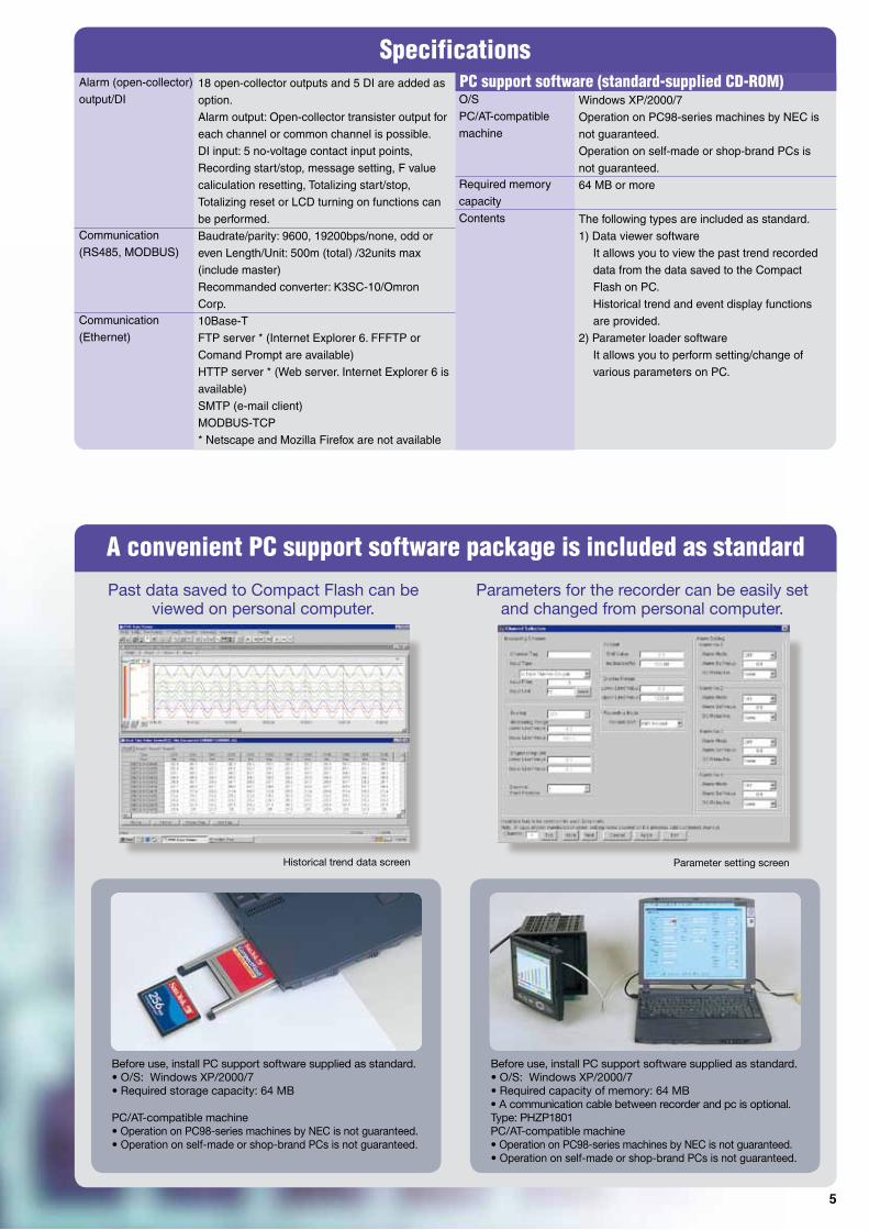
A convenient PC support software package is included as standard
Past data saved to Compact Flash can be viewed on personal computer.
Parameters for the recorder can be easily set and changed from personal computer.
Before use, install PC support software supplied as standard. • O/S: Windows XP/2000/7• Required storage capacity: 64 MB PC/AT-compatible machine • Operation on PC98-series machines by NEC is not guaranteed.• Operation on self-made or shop-brand PCs is not guaranteed.
Before use, install PC support software supplied as standard.• O/S: Windows XP/2000/7• Required capacity of memory: 64 MB• A communication cable between recorder and pc is optional.Type: PHZP1801 PC/AT-compatible machine • Operation on PC98-series machines by NEC is not guaranteed.• Operation on self-made or shop-brand PCs is not guaranteed.
Historical trend data screen Parameter setting screen
Specifications PC support software (standard-supplied CD-ROM) Alarm (open-collector)
output/DI
Communication
(RS485, MODBUS)
Communication
(Ethernet)
O/S
PC/AT-compatible
machine
Required memory
capacity
Contents
18 open-collector outputs and 5 DI are added as
option.
Alarm output: Open-collector transister output for
each channel or common channel is possible.
DI input: 5 no-voltage contact input points,
Recording start/stop, message setting, F value
caliculation resetting, Totalizing start/stop,
Totalizing reset or LCD turning on functions can
be performed.
Baudrate/parity: 9600, 19200bps/none, odd or
even Length/Unit: 500m (total) /32units max
(include master)
Recommanded converter: K3SC-10/Omron
Corp.
10Base-T
FTP server * (Internet Explorer 6. FFFTP or
Comand Prompt are available)
HTTP server * (Web server. Internet Explorer 6 is
available)
SMTP (e-mail client)
MODBUS-TCP
* Netscape and Mozilla Firefox are not available
Windows XP/2000/7
Operation on PC98-series machines by NEC is
not guaranteed.
Operation on self-made or shop-brand PCs is
not guaranteed.
64 MB or more
The following types are included as standard.
1) Data viewer software
It allows you to view the past trend recorded
data from the data saved to the Compact
Flash on PC.
Historical trend and event display functions
are provided.
2) Parameter loader software
It allows you to perform setting/change of
various parameters on PC.
6
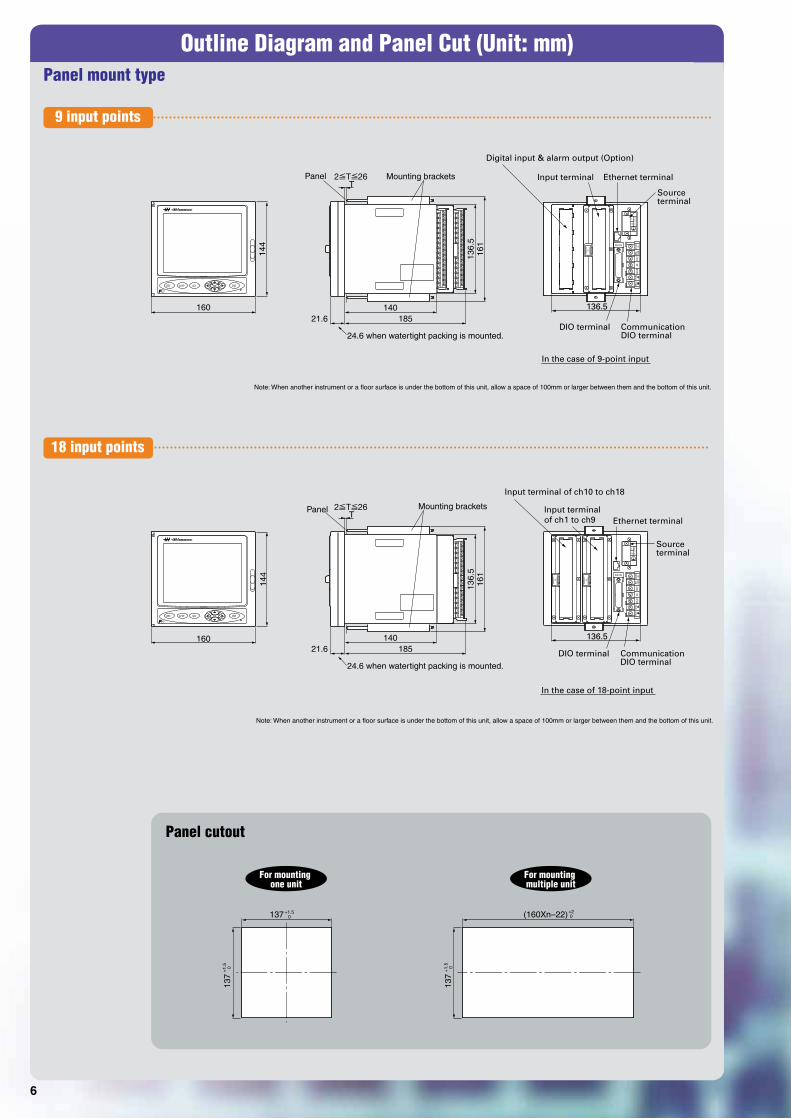
Outline Diagram and Panel Cut (Unit: mm)
144
160 136.5
Digital input & alarm output (Option)
Communication DIO terminal
DIO terminal
Input terminal Ethernet terminal
Source terminal
Communication DIO terminal
DIO terminal
In the case of 9-point input
136.5
Input terminal of ch10 to ch18
Input terminal of ch1 to ch9 Ethernet terminal
In the case of 18-point input
161
Source terminal
136.
5
140 185 21.6
T 2 T 26 Panel Mounting brackets
24.6 when watertight packing is mounted.
Note: When another instrument or a floor surface is under the bottom of this unit, allow a space of 100mm or larger between them and the bottom of this unit.
Note: When another instrument or a floor surface is under the bottom of this unit, allow a space of 100mm or larger between them and the bottom of this unit.
144
160
161
136.
5
140 185 21.6
T Panel Mounting brackets
24.6 when watertight packing is mounted.
137 +1.5 0 (160Xn–22) +2
0
137
+1.
5 0
137
+1.
5 0
For mounting multiple unit
For mounting one unit
2 T 26
9 input points
18 input points
Panel mount type
Panel cutout
100~
240V
AC
N
L
R-M
OD
ULE
Rcj
Fuji
Elec
tric
DIO-CN
TRX1
TRX2
SHLD
DO11
DIO-
COM
24VD
CIN
A6
DIO-ON
TRX1
TRX2
SHLD
DO11
DIO-
COM
24VD
CIN
A6
R-M
OD
ULE
Fuji
Elec
tric
Rcj
Fuji
Elec
tric
Rcj
R-M
OD
ULE
100~
240V
AC
L
N
7
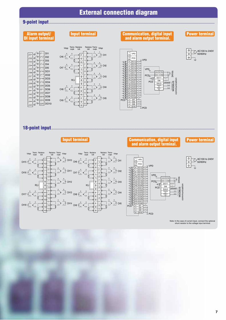
External connection diagram
DI1231DI2
DI3
DI4
DI5
DO1
DO2
DO3
DO4
DO5
DO6
DO7
DO8
DO9
DO10
Alarm output/DI input terminal
Communication, digital input and alarm output terminal.
Communication, digital input and alarm output terminal.
Input terminal
VoltageVoltage
CH6
CH7
RCJ
CH8
CH9
+ +
+ +
+ +
+ +
+ +
– –+ +
– –
+ +
– –
+ +
– –
+ +
–
+
–+
–
+
–
+
–
+
–
+
–
+
–
+
–
+
–
+
–
+
–
+
–
+
–
+
–
+
–
+
–
+
–
+
–
+
–
+
–
+
–
+
–
+
–
+
–
+
–
+
–
+
–
+
–
+
–
+
–
+
–
+
–
+
–
+
–
+
–
+
–
–
– –
– –
– –
– –
CH1
CH2
CH3
CH4
CH5
AC100 to 240V50/60Hz
232
233
234
235
236
237
238
239
240
241
242
243
244
245
211
212
213
214
215
216
217
218
219
220
221
222
223
224
225
6111
6212
6313
7121
7222
7323
31
32
33
8141
8242
8343
9151
9252
9353
Input terminal
CH6
CH7
RCJ
CH8
CH9
Note: In the case of current input, connect the optional shunt resistor to the voltage input terminal.
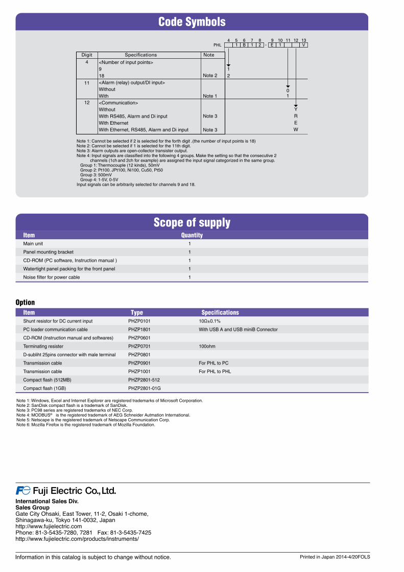
Note 1: Cannot be selected if 2 is selected for the forth digit .(the number of input points is 18)Note 2: Cannot be selected if 1 is selected for the 11th digit.Note 3: Alarm outputs are open-collector transister output.
Specifications
4 5 6 7 8 PHL
4
11
12
12
2 1 E
YREW
V 1 1 B -
01
<Number of input points>918<Alarm (relay) output/DI input>WithoutWith<Communication>WithoutWith RS485, Alarm and Di inputWith EthernetWith Ethernet, RS485, Alarm and Di input
9 10 11 12 13
Digit
Note 2
Note 3
Note 1
Note 3
Note
Note 4: Input signals are classified into the following 4 groups. Make the setting so that the consecutive 2 channels (1ch and 2ch for example) are assigned the input signal categorized in the same group.
Group 1: Thermocouple (12 kinds), 50mV Group 2: Pt100. JPt100, Ni100, Cu50, Pt50 Group 3: 500mV Group 4: 1-5V, 0-5VInput signals can be arbitrarily selected for channels 9 and 18.
OptionItem Type Specifications Shunt resistor for DC current input PHZP0101 10Ω±0.1%
PC loader communication cable PHZP1801 With USB A and USB miniB Connector
CD-ROM (Instruction manual and softwares) PHZP0601
Terminating resister PHZP0701 100ohm
D-subliht 25pins connector with male terminal PHZP0801
Transmission cable PHZP0901 For PHL to PC
Transmission cable PHZP1001 For PHL to PHL
Compact flash (512MB) PHZP2801-512
Compact flash (1GB) PHZP2801-01G
Note 1: Windows, Excel and Internet Explorer are registered trademarks of Microsoft Corporation.Note 2: SanDisk compact flash is a trademark of SanDisk.Note 3: PC98 series are registered trademarks of NEC Corp.Note 4: MODBUS® is the registered trademark of AEG Schneider Autmation International.Note 5: Netscape is the registered trademark of Netscape Communication Corp.Note 6: Mozilla Firefox is the registered trademark of Mozilla Foundation.
Printed in Japan 2014-4/20FOLS
International Sales Div.Sales GroupGate City Ohsaki, East Tower, 11-2, Osaki 1-chome,Shinagawa-ku, Tokyo 141-0032, Japanhttp://www.fujielectric.comPhone: 81-3-5435-7280, 7281 Fax: 81-3-5435-7425http://www.fujielectric.com/products/instruments/
Information in this catalog is subject to change without notice.


![Paperless Recorder GX10 - Yokogawa Paperless Recorder GX10 Unit: mm (approx. inch) SD 04L51B01-01EN [ Main Unit ] External Dimensions *1: with modules *2: without moduels Unless otherwise](https://static.documents.pub/doc/80x56/5b276dbd7f8b9a34208b6391/paperless-recorder-gx10-yokogawa-paperless-recorder-gx10-unit-mm-approx-inch.jpg)


