135
PAPERLESS RECORDER TYPE: PHL INP-TN1PHLa-E Instruction Manual

PAPERLESS RECORDER
TYPE: PHL
INP-TN1PHLa-E
Instruction Manual

iINP-TN1PHL-E
Congratulations on your purchase of Fuji Paperless Recorder (Type: PHL)
• Read this instruction manual carefully to ensure correct installation, operation and preparation.Incorrect handling may lead to accident or injury.
• Specifications of this unit is subject to change without prior notice for improvement.
• Modification of this unit without permission is strictly prohibited.Fuji will not be bear any responsibility for a trouble caused by such a modification.
• This instruction manual should be kept by the person who is actually using the unit.
• After reading the manual, be sure to keep it at a place easy to access.
• This instruction manual should be delivered to the end user without fail.
Manufacturer : Fuji Electric Instruments Co., Ltd.
Type : Shown on nameplate of Paperless Recorder
Date of manufacture : Shown on nameplate of Paperless Recorder
Product nationality : Japan
(Note) Windows 98/2000/XP, Excel, WORD PAD are registered trademarks of MicrosoftCorporation.
(Note) Compact Flash is a trademark of Sandisk Corporation.
Request
• It is prohibited to transfer part or all of the manual withoutFuji’s permission.
• Description in this manual will be changed without priornotice.
© Fuji Electric Instruments Co., Ltd. 2004
Issued in April, 2004
Rev. 1st edition June, 2004
PREFACE

ii INP-TN1PHL-E
DANGER
Read this “Caution on Safety” carefully before using the instrument.
• Be sure to observe the instructions shown below, because they describe important information on safety.The degree of danger is classified into the following two levels: “DANGER” and “CAUTION.”
The signs and their meanings are as follows:
Improper handling may cause dangerous situations that mayresult in death or severe injury.
Improper handling may cause dangerous situations that mayresult in moderate or light injuries or property damage.
CAUTION ON SAFETY
• When there is a possibility that the abnormality of this instrument may cause a major accident ordamage to other instruments, externally install an adequate emergency stop circuit or a protectioncircuit to prevent accidents.
• This product is provided with a built-in fuse that cannot be replaced by the customer. Therefore, werecommend you to separately provide adequate fuses externally. (Rating: 250V, 1A)The details of the built-in fuse are as follows.
Type: TR-5 19372, 3.15A (Manufactured by Wickmann-Werke GmbH)Rating: 250V, 3.25A, Type: T (Slow-blow type)
• Feed the power-supply voltage to specifications to prevent damages to and breakdown of the instru-ment.
• Never turn on the power before all the mounting and wiring work are finished to prevent electricshock, malfunction or failure of the instrument.
• Never use this instrument in an environment where flammable or explosive gases exist, since this isnot of intrinsically safe construction.
• Never disassemble, remodel, modify, or repair this instrument. Otherwise malfunction, electricshock, or failure may result.
• Never touch the terminal while the instrument is being energized. Otherwise electric shock ormalfunction may result.
• Turn off the power before attaching/detaching the module/unit. Otherwise electric shock, malfunc-tion or failure may result.
• We recommend you to perform periodic maintenance for the safe and continuous use of this instru-ment, because consumable parts or those which deteriorate with time are mounted in this instrument.
• Do not block the ventilation holes at the top and the bottom of this instrument. Otherwise a failure,malfunction, shortened service life, or fire may result.
DANGER
CAUTION
iiiINP-TN1PHL-E
• Never use the instrument if it is found damaged or deformed when unpacked. Otherwise a fire, mal-function, or failure may result.
• Check that the instrument is to the proper specifications. Otherwise damage or failure may result.
• Do not give a shock to the instrument by falling or toppling it. Otherwise damage or failure may result.
• Operate the instrument paying attention to prevent foreign matters such as scraps, electric wire chips,and iron powder from entering in the instrument.
• Check every six months that the terminal screws and mounting screws are securely fastened. Loosescrews may cause fire or malfunction.
• When changing the setting during the operation or forcibly outputting, starting or stopping the instru-ment, be sure to check that safety is ensured. Improper operation may result in damage or failure of theinstrument.
• Be sure to keep the attached terminal cover mounted on the terminal block during the operation. Oth-erwise electric shock or fire may result.
• Never install this instrument in the following environments.
A place where the ambient temperature goes beyond the range from 0 to 50°C (0 to 40°C when theinstrument is mounted with its side face closely contacted, and in the case of portable type)
A place where the ambient humidity goes beyond the range from 20 to 80% RH
A place where condensation occurs
A place where corrosive gases (sulfuric gases or ammonia, etc., in particular) or flammable gasesexist
A place where vibration or impact may be applied to the instrument (permissible continuous vibra-tion condition: 4.9 m/s2 or lower)
A place subjected to water, oil, chemicals, vapor, or steam
A place subjected to dust and high in salt or iron content
A place where inductive interference may have a great effect, thus causing static electricity, magne-tism, or noises
A place subjected to heat accumulation by radiant heat or the like
If the instrument is installed near other electronics instruments, such as TV in particular, noises maybe caused. Take the following measures in these cases.
• Place the instrument as far from the TV or the radio as possible (1m or more)
• Change the orientation of the antenna of the TV or the radio.
• Use separate receptacles.
• When mounting this instrument against the panel, pay attention not to apply stress to the case. Other-wise the case may be damaged.
• Stop using the instrument if it is immersed in water. Otherwise electric leak, electric shock, or fire mayresult.
• Do not use the wires other than the specified compensation conducting wires for the thermocoupleinput connection. Otherwise improper indication or malfunction may result.
• Use a wire material with low wire resistance and with small resistance difference among the threewires for the resistance bulb input connection. Otherwise improper indication or malfunction mayresult.
CAUTION

iv INP-TN1PHL-E
• If a large noise is generated from the power supply, provide an isolating transformer and use a noisefilter.
• Never use organic solvents such as alcohol or benzene when cleaning this instrument. Do not directlywater the main unit. Otherwise deterioration, failure, electric leak, electric shock, or fire may result.When cleaning the main unit, wipe with a dry cloth.
• Dispose the instrument as an industrial waste.
• Be sure to ground the instrument. Otherwise electric shock or malfunction may result.
• Only authorized workers should perform wiring. Improper wiring may cause fire, failure, or electricshock.
CAUTION

vINP-TN1PHL-E
CONTENTS
PREFACE ..................................................................................................................... i
CAUTION ON SAFETY ............................................................................................ ii
CONTENTS ................................................................................................................. v
1. INTRODUCTION ............................................................................................ 1-1
1.1 Paperless recorder ...............................................................................................1-1
1.2 Product check......................................................................................................1-1
1.3 Check on type and specification .........................................................................1-2
1.4 Handling memory card (Compact Flash) – Cautions on handling .....................1-2
2. NAMES AND FUNCTIONS OF PARTS ....................................................... 2-1
2.1 Names and functions of parts .............................................................................2-1
2.2 Inserting and removing the memory card ...........................................................2-3
2.3 Recording data to memory card ..........................................................................2-4
3. MOUNTING METHOD .................................................................................. 3-1
3.1 Mounting location ...............................................................................................3-1
3.2 External dimensions and panel cutout dimensions (unit: mm) ...........................3-1
3.3 Method of mounting onto panel .........................................................................3-2
4. WIRING ........................................................................................................... 4-1
4.1 Before wiring ......................................................................................................4-1
4.2 Connection to terminals ......................................................................................4-2
4.3 Connection the recorder to loader..................................................................... 4-11
5. PORTABLE ..................................................................................................... 5-1
5.1 Portable ...............................................................................................................5-1
5.2 Handling .............................................................................................................5-1
5.3 Outside dimension (unit: mm) ............................................................................5-2
5.4 External connection diagram ..............................................................................5-2
6. DISPLAY FUNCTION....................................................................................... 6-1
6.1 Basic composition of Data Display screen .........................................................6-1
6.2 Real time trend display of measured data ...........................................................6-3
6.3 Display of measured data in bar graphs or analog meters ..................................6-5
6.4 Digital display of measured data ........................................................................6-6
6.5 Totalizing data display ........................................................................................6-6
6.6 Event summary display.......................................................................................6-8
6.7 Historical trend display .......................................................................................6-9
6.8 Display at the occurrence of main unit failure..................................................6-10
Refer to chapters 3 and 4 only when installing this instrument. Onlyqualified workers should carry out mounting and wiring of this instrument.CAUTION

vi INP-TN1PHL-E
6.9 Cautions about power ON/OFF ........................................................................6-11
7. OPERATION AND ACTIONS........................................................................ 7-1
7.1 Before running the recorder ................................................................................ 7-1
7.2 Power ON and state ............................................................................................ 7-2
7.3 Stopping and starting the recording operation .................................................... 7-3
7.4 Switching data display screens ........................................................................... 7-5
7.5 Display of alarm .................................................................................................7-6
8. SETTING AND CHECKING PARAMETERS ............................................... 8-1
8.1 Setting and checking ........................................................................................... 8-1
8.2 Outline of parameter setting procedure ..............................................................8-6
8.3 Basic operation of setting screens....................................................................... 8-7
9. SETTING PARAMETERS .............................................................................. 9-1
9.1 Basic setting ........................................................................................................ 9-1
9.2 Channel setting ................................................................................................... 9-6
9.3 Copying parameters .......................................................................................... 9-22
9.4 Setting calculation function .............................................................................. 9-24
9.5 Setting timer for calculation ............................................................................. 9-30
9.6 Setting method of data display screen ..............................................................9-32
9.7 Setting method of F value calculation (Setting common to all channels) ........ 9-36
9.8 Setting totalizing ...............................................................................................9-38
9.9 Setting method of messages.............................................................................. 9-42
9.10 Unit definition ................................................................................................... 9-44
9.11 Setting method of DI (external control unit) function ......................................9-45
9.12 Setting constant .................................................................................................9-47
9.13 Setting password for parameter setting.............................................................9-48
10. OPERATING MEMORY CARD .................................................................. 10-1
10.1 Displaying record data of memory card ...........................................................10-1
10.2 Removing memory card (compact flash) ......................................................... 10-4
10.3 Totalizing start/stop setting............................................................................... 10-6
10.4 Setting password for memory card operation ................................................... 10-8
11. MAINTENANCE AND INSPECTION ......................................................... 11-1
11.1 Recommended replacement cycle of parts ....................................................... 11-1
11.2 Calibration ........................................................................................................ 11-1
11.3 Formatting the memory card ............................................................................ 11-1
12. CALIBRATION.............................................................................................. 12-1
12.1 Calibration method of measured values ...........................................................12-1
12.2 Initializing the measured value .........................................................................12-3

viiINP-TN1PHL-E
13. TROUBLESHOOTING .................................................................................. 13-1
14. SPECIFICATIONS ......................................................................................... 14-1
APPENDICES ........................................................................................................ A-1
Appendix 1 Recording format (ASCII) ...................................................................... A-1
Appendix 2 Parameters that cannot be set during recording ...................................... A-3
Appendix 3 Parameters that cannot be set while totalizing is under way ................... A-3
Appendix 4 Opening the PHL record data in ASCII format on Excel ....................... A-4
Appendix 5 Timing of recording ................................................................................ A-5

1-1INP-TN1PHL-E
We thank you for purchasing Fuji Paperless Recorder PHL.
The instruction manual describes installation, operation, and maintenance of Paperless Recorder. Read thismanual carefully before use.
1.1 Paperless recorder(1) This recorder displays measured data in real time on the liquid crystal display. It is a paperless
type that is also capable of saving the measured data to a compact flash card.
(2) It can set up to 18 channels for the input types such as thermocouple, resistance bulb, and DCvoltage (or current).
(3) It allows the measured data saved to the compact flash card to be displayed on the display unit.Use of the support software attached to the recorder allows the saved data to be displayed on apersonal computer.
1.2 Product checkUpon receiving the recorder unit, check the appearance for damage, and if the correct quantity of theaccessories are supplied.
Check on accessories
This recorder comes with the accessories shown in Fig. 1-1. Check that they are all present.
1. INTRODUCTION
Fig. 1-1 Accessories
qPanel-mountingbracket
ePC support software(CD-ROM)
wMemory card(Compact Flash card)
rPanel packing yPower supply noise filter
tAC power cord
Product name
Panel-mounting bracket
CD-ROM PC support software instruction manual
–
1
Waterproof panel packing for front face –
QuantityPortablePanel-mounted
2
1
1AC power cord (2m)
q
Compact flash (16MB) 11w
e
r
t 1–Power supply noise filtery 11

1-2 INP-TN1PHL-E
1.4 Handling memory card (Compact Flash)– Cautions on handling
(1) For the memory card, use Sandisk’s compact flash memory (URL: http://www.sandisk.co.jp).Other memory cards may cause trouble to the recorder.
1) When formatting the memory card, use a personal computer. (Refer to 11.3)as FAT16 or FAT
2) The memory card should be inserted in the proper direction and fixed securelyto the slot.
3) Don’t turn OFF the power or remove the card from the slot while data is beingwritten in or read from the card, or recorded data may be damaged or lost.
4) Measured data saved to the memory card should be backed up, if necessary.
5) Using CF card adaptor, please check how many capacities it can deal with. Ifyour CF card is out of the range, don’t format CF card using the adaptor.When format CF card by the adaptor, you may find it complete format on theWindows. But in that case, PHL might not read the card.
1.3 Check on type and specificationCode symbols are marked on specification nameplates. Check the type as ordered. (The specificationnameplates are attached to the right of the case and at the rear of the display unit).
Item
4 5 6 7 8
4
5
9
11
12
12
1 E 1 Y1B3L
2H
1P -
12
E
01
Number of input points
Mounting
Display
Alarm (relay) output/DI input board
Communication/alarm (open collector) output/DI input board
9 10 11 12 13
Digit
9-point input18-point input
Panel mountPortable (Note 3)
English
WithoutWith (Note 1)
WithoutWith (Note 2)
Specifications
YR
Note 1: If you select 2 (18-point input) for the 4th digit of the code symbol, you cannot select 1 for the 11th digit (alarm output/DI input board).
Note 2: If alarm output/DI input for 18-point input is required, select R for the 12th digit (communication/alarm output/DI input board).
Note 3: Portable type is not approved by UL and CE marking.
CODE SYMBOLS
CAUTION

1-3INP-TN1PHL-E
(2) Compact flash in the capacity range from 8MB to 256MB can be used.
Refer to the following tables for the storage capacity in the case of 9-channel recording (oncondition that no events such as alarms or messages are occurring, and that totalizing is stopped).
(The number of days required for 18-channel recording is approximately one half of those shownin the table.)
(3) Data write to the memory card is performed according to the following timing. If the power isOFF in the writing cycle, note that the data will not be recorded.
Display refresh cycle
Compact flash size 16MB
1 sec 10 sec 30 sec 1 min 10 min 30 min
Recordable capacity(about)
ASCII format 28 hours 11 days 35 days 70 days 2 years 5.7 years
Binary format
Display refresh cycle
Compact flash size
Recordable capacity(about)
ASCII format
Binary format
Display refresh cycle
Compact flash size
Recordable capacity(about)
ASCII format
Binary format
112 hours 44 days 140 days 280 days 8 years 22.8 years
64MB
1 sec 10 sec 30 sec 1 min 10 min
112 hours 46 days 140 days 280 days 7.7 years
448 hours 184 days 560 days 1,120 days 30.8 years
256MB
1 sec 10 sec 30 sec 1 min
18 days 187 days 1.5 years 3 years
72 days 748 days 6 years 12 years
Note: Refer to Item 9.1 “Basic Setting” for the selection of ASCII or binary format for data recording.
Display refresh cycle 1 sec to 1min 2 min 3 min 5 min 10 min 30 min
Write cycle 1 min 2 min 3 min 5 min 10 min 30 min
20 min
20 min
Display refresh cycle 1 hour 2 hours 3 hours 4 hours 6 hours
Write cycle
12 hours
1 hour 2 hours 3 hours 4 hours 6 hours 12 hours
(4) The data recorded in the compact flash can be regenerated on the PC by using the data viewer(contained in the attached CD-ROM).
If the data is recorded in ASCII format, it can be directly opened in a spreadsheet such as EXCEL.However, large-amount data cannot be opened (about 10MB or larger in the case of 9-point input,and about 5MB or larger in the case of 18-point input).
In those cases, read in data with the data viewer (contained in the attached CD-ROM), and per-form CSV conversion to divide the file, which allows the data to be read in.
The data recorded in binary format cannot be directly opened in a spreadsheet such as EXCEL.Refer to Item 9.1 “Basic Setting” for details.
(5) Removing memory card
By prohibiting the writing on the memory card, the card can be taken out even if the recording orintegration is not stopped. Refer to Item 10.2 “Removing memory card (compact flash)” for theprocedure.

2-1INP-TN1PHL-E
2. NAMES AND FUNCTIONS OF PARTS
(4) Memory card ejection button(6) Function keyboard
(3) Memory card slot
(2) Power switch(5) Connector forparameter loader
(1) Display unit
2.1 Names and functions of parts
(1) Display unit
Allows the Real time trend screen, Bar Graph Display screen, Analog meter screen, DigitalDisplay screen, Totalizing data display screen, Historical trend screen and other various ParameterSet screens to be displayed.
(2) Power switch
Used to turn the power ON or OFF.
(3) Memory card slot
Used for inserting the memory card
(4) Memory card ejection button
To remove the memory card from the slot, press this button.
If you want to remove the memory card while recording is in progress (while RECin the display unit is highlighted) or during totalizing, refer to Item 10.2 or stoprecording and totalizing before removing the memory card. Otherwise, the datacannot be recorded correctly, or the past data may be damaged. (If the memorycard is removed and inserted again while recording or totalizing is in progress, it isrecorded as a new file.)
(5) Connector for parameter loader
When changing parameters by using a loader, connect the exclusive cable (optional cable:PHZP0201) to the connector.
(6) Function keyboard
Used for operation, or setting and verifying each parameter.
CAUTION

2-2 INP-TN1PHL-E
Used to start or stop recording.
Pressing once, starts recording. After that pressing once again, stops recording.
Used to switch display contents. Each time the key is pressed, the display is switched to q → w → e → r → t → y and returns to q.
q Real time trend display
Displays the measurement data of an arbitrary channel on data display screen (note 1)
w Key guidance
Key operation guidance appears.
e Bar graph/analog meter display
Displays the measured data of the channel in a bar graph (or analog meter).
At the shipment, it is set to display “Bar graph meter display”.
r Digital display.
Displays the measured data of the channel in numerical values.
t Totalizing data display
Displays the totalizing data of an arbitrary channel in numerical values.
y Event summary display
Displays the alarm summary or message summary.
Pressing this key on the parameter setting screen (note 2), the display is swithed to the Real time
trend display.
Used to switch from the data display screen (note 1) to the parameter setting screen (note 2).
Pressing the key on the parameter setting screen switches to the screen one step up.
However, pressing the key on the menu screen does not change screens.
q Used for selection on the setting screen or registration of the set data.
w If the key is pressed while the scales are displayed on the real time trend display screen,
historical trend display screen (*1), or recorded data display screen, the channels for which
scales are to be displayed can be switched.
(Scale of ch1 → scale of ch2 → ….. → scale of ch9 → scale of ch1 → scale of ch2…..)
q Used to select setting items.
w Used to increase or decrease numerical values.
e Pressing the key on the real time trend displays the historical trend screen (*1).
At this time, the window can be scrolled using the cursor key.
r Pressing the or key on the real time trend display, bar graph/analog meter display,
digital display screen or totalizing data display screen is changed, as shown below.
Press key : group 1 → 2 → 3 → 4 → 1 → ...Press key : group ... ← 4 ← 1 ← 2 ← 3 ← 4
Key name
(Record)
(Display)
(Select)
(Entry)
(Cursor)
Function
*1: The screen in the past of the data currently recorded
*1: The screen in the past of the data currently recorded
Note 1 : See Item 7.4 for detail.Note 2 : See Item 8.1 for detail.

2-3INP-TN1PHL-E
Memory card ejection button
2.2 Inserting and removing the memory cardThe memory card is used for saving measured data. Before attempting to use the recorder, set it in therecorder slot securely.
This section explains how to insert the memory card into or remove it from the slot.
(1) To insert memory card
Step 1) Open the panel unit.
Step 2) Insert the memory card into the slot at theright side of the panel unit as shown inPhoto.
Insert straight the card in accor-dance with the photo, or theinside pins might be broken. Ifyou insert with wrong direction,the slot is broken.
(2) To remove memory card
Step 1) Press the memory card ejection button to remove thememory card from the slot.
qqqqq Do not remove the memory cardwhile data is written in it (while thelamp indicating writing status is kepton). Refer to Item 8.19 “Removingmemory card (compact flash)” forthe removal of the memory cardwhile recording is in progress.
wwwww After inserting the memory card intothe slot, don’t remove the card untilthe recorder can acknowledge it.
eeeee Be careful with static electricity whenremoving the memory card.
CAUTION
CAUTION

2-4 INP-TN1PHL-E
Display refresh cycle
Compact flash size 16MB
1 sec 10 sec 30 sec 1 min 10 min 30 min
Recordable capacity(about)
ASCII format 28 hours 11 days 35 days 70 days 2 years 5.7 years
Binary format
Display refresh cycle
Compact flash size
Recordable capacity(about)
ASCII format
Binary format
Display refresh cycle
Compact flash size
Recordable capacity(about)
ASCII format
Binary format
112 hours 44 days 140 days 280 days 8 years 22.8 years
64MB
1 sec 10 sec 30 sec 1 min 10 min
112 hours 46 days 140 days 280 days 7.7 years
448 hours 184 days 560 days 1,120 days 30.8 years
256MB
1 sec 10 sec 30 sec 1 min
18 days 187 days 1.5 years 3 years
72 days 748 days 6 years 12 years
Note: Refer to Item 9.1 “Basic Setting” for the selection of ASCII or binary format for data recording.
2.3 Recording data to memory card(1) Recorded data:
Data can be recorded in the following three formats. Either ASCII or binary format can beselected for recording. Refer to Item 9.1 “Basic Setting.”
Trend data : Records the maximum and the minimum values, average value or instan-taneous values of the measured value sampled at display update cycles.
Trend data file name to be created: S00****.FDT (**** is substituted byfour-digit numerical value.)
Refer to “Appendix 1 (1) Trend data file” for recording format.
Event data : Records the information on occurrence or release of alarms and messageissuing information.
Event data file name to be created: A00****.FDT (**** is substituted byfour-digit numerical value.)
Refer to “Appendix 1 (2) Event data file” for recording format.
Totalizing data: Records the totalizing data every totalize recording cycle.
Totalizing data file name to be created as shown below.
Periodic : T000000.FDTDairy : D000000.FDTWeekly : W000000.FDTMonthly : M000000.FDTAnnual : Y000000.FDTDairy (Time set) : R000000.FDTExternal : E000000.FDT
(2) Recording capacity:
It depends on the capacity of the memory card.
Refer to the following tables for the storage capacity in the case of 9-channel recording (oncondition that no events such as alarms or messages are occurring, and that totalizing is stopped).
(The number of days required for 18-channel recording is approximately one half of those shownin the table.)

2-5INP-TN1PHL-E
Display reflesh cycle 1 sec to 1min 2 min 3 min 5 min 10 min 30 min
Writing cycle 1 min 2 min 3 min 5 min 10 min 30 min
20 min
20 min
Display reflesh cycle 1 hour 2 hours 3 hours 4 hours 6 hours
Writing cycle
12 hours
1 hour 2 hours 3 hours 4 hours 6 hours 12 hours
(3) Recording cycle:
Refer to the following tables for the timing of writing the trend data to the compact flash.
The event data is written in the compact flash by the minute.
(4) Timing to start recording:
The event data cannot be written in the compact flash until the first display refreshment cyclepasses by.
3-1INP-TN1PHL-E
3. MOUNTING METHOD
∠α = 60 to 90°
∠α
144
161
136.
5
160 140
18521.6
T2 ≤ T ≤ 26Panel Mounting bracket
24.6 when waterproof packing is used
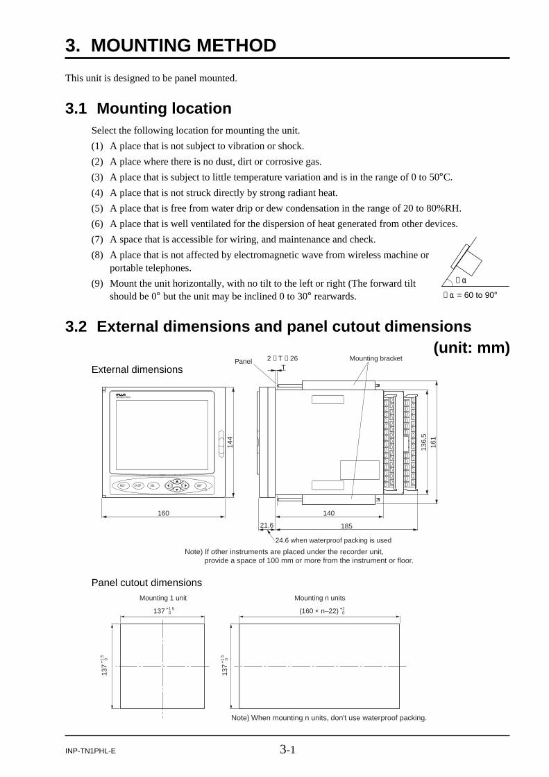
Note) If other instruments are placed under the recorder unit, provide a space of 100 mm or more from the instrument or floor.
Note) When mounting n units, don't use waterproof packing.
137 +1.50 (160 × n–22) +2
0
137
+1.
50
137
+1.
50
Mounting 1 unit Mounting n units
This unit is designed to be panel mounted.
3.1 Mounting locationSelect the following location for mounting the unit.
(1) A place that is not subject to vibration or shock.
(2) A place where there is no dust, dirt or corrosive gas.
(3) A place that is subject to little temperature variation and is in the range of 0 to 50°C.
(4) A place that is not struck directly by strong radiant heat.
(5) A place that is free from water drip or dew condensation in the range of 20 to 80%RH.
(6) A place that is well ventilated for the dispersion of heat generated from other devices.
(7) A space that is accessible for wiring, and maintenance and check.
(8) A place that is not affected by electromagnetic wave from wireless machine orportable telephones.
(9) Mount the unit horizontally, with no tilt to the left or right (The forward tiltshould be 0° but the unit may be inclined 0 to 30° rearwards.
3.2 External dimensions and panel cutout dimensions (unit: mm)
External dimensions
Panel cutout dimensions

3-2 INP-TN1PHL-E
Panel Mounting bracket
3.3 Method of mounting onto panel
• Using the supplied mounting bracket, tighten the upper and lower screws unit the panel is fixed.
• The panel to be used should be more than 2 mm and less than 26 mm thick.
CAUTION Excessive torque will cause damage to front panel frame or result in casedeformation.
Torque: 0.2 N·m
• If the panel front is subject to water splashes, use panel packing between the unit and panel.

4-1INP-TN1PHL-E
4. WIRING
For M3screw terminal
4.1 Before wiring(Note) When cables are connected to terminals of the recorder unit, don’t apply pulling force to them
excessively. Excessive force to the terminal may result in damage to the terminal or cable.
(1) Use the power cable that has the performance equivalent to or higher than 600-V vinyl insulatedpower cable.
(2) For the thermocouple input, be sure to use a compensated lead wire.
(3) Input signal cables should be wired separately as far as possible (30 cm or more) from power linesand high-voltage lines to minimize the effect of inductive noise. Shielded cables should prefer-ably be used. In this case, the shield braids should be earthed at one point.
(4) Up to 2 solderless terminals should be used when connecting cables to terminals. Be sure to usean insulation cap.
(Note)
1) At the completion of wiring of the input terminals, be sure to close the rear cover to ensurethe compensation of reference contact when thermocouple input is used.
In case of thermocouple input, follow the steps to stabilize temperature at the terminal.
• Be sure to attach input terminal cover.
• Don’t use a thick cable to prevent the effect of radiation. It is recommended that the cablewith a diameter of 0.5 mm or less should be used.
• Don’t mount other instruments near a fan to keep temperature stable.
2) For connection of lead wires to terminals, use of sleeve-insulated clamping terminals isrecommended.
3) This product is provided with a built-in fuse that cannot be re-placed by the customer. Therefore, we recommend you to sepa-rately provide adequate fuses externally. (Rating: 250V, 1A)
4) Don’t loosen screws that are secured to the terminal case andpower terminal.
4-2 INP-TN1PHL-E
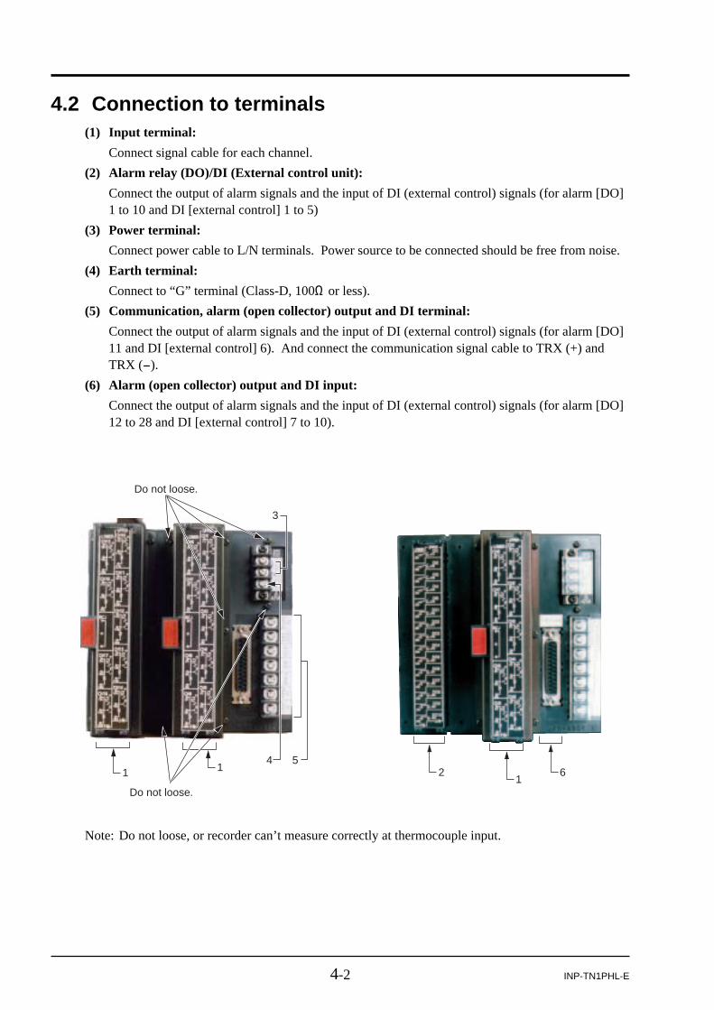
4.2 Connection to terminals(1) Input terminal:
Connect signal cable for each channel.
(2) Alarm relay (DO)/DI (External control unit):
Connect the output of alarm signals and the input of DI (external control) signals (for alarm [DO]1 to 10 and DI [external control] 1 to 5)
(3) Power terminal:
Connect power cable to L/N terminals. Power source to be connected should be free from noise.
(4) Earth terminal:
Connect to “G” terminal (Class-D, 100Ω or less).
(5) Communication, alarm (open collector) output and DI terminal:
Connect the output of alarm signals and the input of DI (external control) signals (for alarm [DO]11 and DI [external control] 6). And connect the communication signal cable to TRX (+) andTRX (-).
(6) Alarm (open collector) output and DI input:
Connect the output of alarm signals and the input of DI (external control) signals (for alarm [DO]12 to 28 and DI [external control] 7 to 10).
4 51 1
Do not loose.
Do not loose.
3
2 61
Note: Do not loose, or recorder can’t measure correctly at thermocouple input.

4-3INP-TN1PHL-E
Input terminal
CH6
CH7
RCJ
CH8
CH9
Resistancebulb
Resistancebulb
ThermocoupleThermocouple
VoltageVoltage
Note) For current input, connect optional shunt resitors to the voltage input terminals.
+
–
+
– CH1
CH2
CH3
CH4
CH5
+
–
+
–
+
–
+
–
+
–
+
–
+
–
+
–
+
–
+
–
+
–
+
–
+
–
+
–
+
–
+
–
6111
6212
6313
7121
7222
7323
31
32
33
8141
8242
8343
9151
9252
9353
+
Resistancebulb
Resistancebulb
ThermocoupleThermocoupleVoltageVoltage
CH6
CH1–
+
–
CH2
+
–CH7
RCJ
CH8
CH9
+
–
CH3
+
–
+
–
CH4
+
–
+
–
CH5
+
–
+
–
+
–
+
–
+
–
+
–
+
–
+
–
+
–
+
–
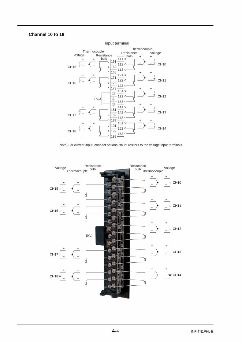
(1) Connection of input terminal
1) Input terminal No. is determined for each channel.
2) When changing the type of input signal (see Item 9.2) after purchasing the unit, connect inputterminals according to the relation between terminal No. and channel No..
Note: Don’t input huge signal that is out of range, or recorder is broken.
Channel 1 to 9
4-4 INP-TN1PHL-E
Channel 10 to 18
CH15
CH16
RCJ
CH17
CH18
+
–
+
– CH10
CH11
CH12
CH13
CH14
+
–
+
–
+
–
+
–
+
–
+
–
+
–
+
–
+
–
+
–
+
–
+
–
+
–
+
–
+
–
161111
162112
163113
171121
172122
173123
131
132
133
181141
182142
183143
191151
192152
193153
Input terminal
Resistancebulb
Resistancebulb
ThermocoupleThermocouple
VoltageVoltage
+
–
Note) For current input, connect optional shunt resitors to the voltage input terminals.
+
CH15
CH10–
+
–
CH11
+
–CH16
RCJ
CH17
CH18
+
–
CH12
+
–
+
–
CH13
+
–
+
–
CH14
+
–
+
–
+
–
+
–
+
–
+
–
+
–
+
–
+
–
+
–
Resistancebulb
Resistancebulb
ThermocoupleThermocoupleVoltageVoltage

4-5INP-TN1PHL-E
Not used
DC current input
Shunt resistor (option)(PHZP0101)
Example 1) For 4 to 20mA and 10 to 50mA input,10Ω±0.1% shunt resistance is used.In this case, set the input rangeto ±500mV (see Item 9.2).
Voltage conversion by shunt resistance of 10Ω4 to 20mA DC : 40 to 200mV DC10 to 50mA DC : 100 to 500mV DC
b
B
A
Red(A)White(B)White(b)
Resistance bulb
(4) Resistance input
(2) DC current input(1) DC voltage input
(3) Themocouple input
Compensating leads
DC voltage input
Not used
Not used
Thermocouple
Note) Avoid using thermocouple input with wiring parallel to other instruments.
Wiring of input terminals
Note)
1) Input signals should be the same for every 2 channels.
Example) ch1: thermocouple
ch2: thermocouple Any type of thermocouple can be set.
ch3: 5V
ch4: 5V 1 to 5V or 0 to 5V can be set.
For the setting method, see Item 9.2.
2) Don’t remove RCJ module, or indication of process variable is not correct at thermocoupleinput.

4-6 INP-TN1PHL-E
External control
(1) Recording start/stop
Recording start/stop by DI
Front key
In recordingstop
In recording
Recording start Recording start
Recording stop Recording stop
ON OFF
External control
(2) F value calculation reset
In F valuecalculation Reset the value Keep on calculating
ON OFF
External control
(3) Totalize reset
In Totalizing Reset the value Keep on totalizing
ON OFF
External control
(4) Totalize start/stop
In totalizingstop Totalizing start
In totalizing Totalizing stop
ON OFF
External control
(5) LCD ON
In LCD off LCD ON
ON OFF
DI1
For DI function, see"Setting of DI function".
DI2
DI3
DI4
DI5
DI1231DI2DI3DI4DI5DO1DO2DO3DO4DO5DO6DO7DO8DO9DO10
Alarm output/DI input terminal
232
233
234
235
236
237
238
239
240
241
242
243
244
245
211
212
213
214
215
216
217
218
219
220
221
222
223
224
225
(2) Alarm relay output (DO)/DI (external control unit) (Option)
Note: This option is in case of 11th digit of CODE SYMBOLS is “1”. If the number of inputpoints is 18, it cannot be mounted.
About external control unit (DI)
1) This instrument is provided with the function of performing “start/stop of recording operation,““F-value computation resetting,” “Start/stop of totalizing,” and “Message display” in responseto the contact signals (DI) received from outside the instrument.
Note 1) DI (external control) unit is not insulated and should be used with a relay connected tothe outside.
External contact capacity: 20V/0.05A DC, 1a contact
Note 2) DI (external control) unit is operated as follows when the front switch is pressed.
The unit action will not be affected by items in the table.

4-7INP-TN1PHL-E
DO1
DO2
DO3
DO4
DO5
DO6
DO7
DO8
DO9
DO10
DI1231DI2DI3DI4DI5DO1DO2DO3DO4DO5DO6DO7DO8DO9DO10
Alarm output/DI input terminal
232
233
234
235
236
237
238
239
240
241
242
243
244
245
211
212
213
214
215
216
217
218
219
220
221
222
223
224
225
Note) If lamps are provided on the outside, set a resistor to prevent rush current. Whenrelays or solenoids are used, set elements for contact protection (diodes or surge kill-ers, etc).
About alarm output (DO)
1) Alarm setting is provided at 4 points for each input channel. Up to 10 points for alarm outputcan be set as an option.
2) When an alarm occurs, the relevant terminals are shorted (ON).
1a contact output: Relay contact capacity : 150V AC/3A, 30V DC/3A (resistive load : DO1)
: 240V AC/3A, 30V DC/3A (resistive load : DO2 toDO10)

4-8 INP-TN1PHL-E
(3) Communication, Alarm output (DO)/DI input
Note) This option is in case of 12th digit of CODE SYMBOLS is “R” .
1) About communication
This is for digital communication function with another instruments. This specification is shownbelow.
Communication terminal
Shield
TRX2(-)
TRX1(+)
Item Specification
Electrical specification Based on EIA RS-485
Transmission system 2-wire, semi-duplicate
Synchronizing system Start-stop synchronous system
Connection format 1 : N
Number connectable units Up to 31 units
Transmission distance 500m max. (total extension distance)
Transmission speed 9600, 19200 bps
Data format Data length
Stop bit
Parity
8 bits
1 bit
none, even, odd (selectable)
Transmission code HEX value (MODBUS RTU mode)
Error detection CRC-16
Isolation Functional isolation between transmission circuit and ground (withstand voltage : 500V AC)

4-9INP-TN1PHL-E
2) About external control unit (DI)
This function is the same as the previous page.
Alarm output/DI input terminal
25 13
24 12
23 11
22 10
21 9
20 8
19 7
18 6
17 5 (DI10)
16 4 (DI9)
15 3 (DI8)
14 2 (DI7) 1
24VdC
DI6
Note 1) DI (external control) unit is not insulated and should be used with a relay connected tothe outside.
External contact capacity: 20V/0.05A DC, 1a contact
Note 2) DI (external control) unit is operated as shown in page 4-6, Note 2), through (1) to (5)when the front switch is pressed.
The unit action will not be affected by items in the table.
+
–
DIO(+24V)
DIO(0V)
DO11
DI6
SHLDTRX2
TRX1
PCD
6251314
VPD1
DO127 DO138 DO149 DO1510 DO1611 DO1712 DO1815 DO1916 DO2017 DO2118 DO2219 DO2320 DO2421 DO2522 DO2623 DO2724 DO282 DI73 DI84 DI95 DI10
PCD
VPD
VPD
PCD
PCD
PCD
24V
dcM
OD
BU
Sco
mm
unic
atio
n
(shield)
(–)
(+)

4-10 INP-TN1PHL-E
3) About alarm output (DO)
1) Alarm setting is provided at 4 points for each input channel. Up to 10 points for alarm outputcan be set as an option.
2) When an alarm occurs, the relevant terminals are shorted (ON).
This output is open collector. Ratings are as follows:
30V DC/100mA (resistive load)
Note) This is not relay output.Do not input over rating voltage or current.
25 13
(DO28) 24 12 (DO18)
(DO27) 23 11 (DO17)
(DO26) 22 10 (DO16)
(DO25) 21 9 (DO15)
(DO24) 20 8 (DO14)
(DO23) 19 7 (DO13)
(DO22) 18 6 (DO12)
(DO21) 17 5
(DO20) 16 4
(DO19) 15 3
14 2 1
24VdC
DO11
+
–
DIO(+24V)
DIO(0V)
DO11
DI6
SHLDTRX2
TRX1
PCD
6251314
VPD1
DO127 DO138 DO149 DO1510 DO1611 DO1712 DO1815 DO1916 DO2017 DO2118 DO2219 DO2320 DO2421 DO2522 DO2623 DO2724 DO282 DI73 DI84 DI95 DI10
PCD
VPD
VPD
PCD
PCD
PCD
24V
dcM
OD
BU
Sco
mm
unic
atio
n
(shield)
(–)
(+)

4-11INP-TN1PHL-E
(RS232C)
4.3 Connection the recorder to loader(1) When connecting the recorder to a loader, use optional PC loader communication cable
(PHZP0201) as shown below.
The loader cable should be connected to 9-pin serial port of PC.
Be sure to display the data display screen (refer to Item 7.4) instead of the param-eter setting screen before using the loader. Otherwise, the set value may not bewritten.
CAUTION
(4) Caution on connection of input signal through barrier
1) Thermocouple input and resistance bulb input
Since the barrier internal resistance is added and causes an error in the measured value, perform“Calibration of measured value” with the input connected to the barrier recorder.
For the calibration method, refer to Item 12.1.
2) When using Fuji Zener Barrier (PWZ), a power supply of 100V AC line (85 to 150V AC) shouldbe used to ensure safe operation of the unit.

5-1INP-TN1PHL-E
5. PORTABLE
5.1 Portable• The instrument can be carried about easily holding the handle.
(Portable type is not approved by UL and CE marking.)
External view
5.2 HandlingObserve the following in handling the instrument.
(1) Preferable use environment
• A place not subjected to vibration or impact
• A place not subjected to dust or corrosive gases
• A place of ambient temperature of 0 to 40°C with minimum temperature change
• A place where the humidity is kept within the range from 20 to 80%RH and not subjected todrops of water.
• A place provided with sufficient ventilation allowing the heat from the instrument to be dis-charged
• A place not subjected to the interference from electromagnetic waves by radio devices or mobilephones
• A place where the instrument is not exposed to the risk of falling.
(2) Notes
• Use the stand in upright position.
• Be sure to return the rear cover to the original position after performing the wiring of the inputor the alarm (DO)/DI terminal.
• Be sure to turn off the power before performing wiring and inspection to avoid receiving elec-tric shock.

5-2 INP-TN1PHL-E
144 20
8.5
49
136.
515
20
160 14018521.6
Foot
Handle
Stand footNote: Use the stand in upright position.
INPUT TERMINAL
CH6
CH7
RCJ
CH8
CH9
Resistance bulb
R.T.D
Thermo-couple
T.C.VoltageDC +
–
+
– CH1
CH2
CH3
CH4
CH5
Resistance bulb
R.T.D
Thermo-couple
T.C.
VoltageDC
+
–
+
–
+
–
+
–
+
–
+
–
+
–
+
–
+
–
+
–
+
–
+
–
+
–
+
–
+
–
+
–
6111
6212
6313
7121
7222
7323
3132
33
8141
8242
8343
9151
9252
9353
5.3 Outside dimension (unit: mm)
5.4 External connection diagramWhen the number of input points = 9: M3 screw

5-3INP-TN1PHL-E
INPUT TERMINAL
CH15
CH16
RCJ
CH17
CH18
Resistance bulb
R.T.D
Thermo-couple
T.C.VoltageDC +
–
+
– CH10
CH11
CH12
CH13
CH14
Resistance bulb
R.T.D
Thermo-couple
T.C.
VoltageDC
+
–
+
–
+
–
+
–
+
–
+
–
+
–
+
–
+
–
+
–
+
–
+
–
+
–
+
–
+
–
+
–
161111
162112
163113
171121
172122
173123
131132
133
181141
182142
183143
191151
192152
193153
When the number of inputs = 18: M3 screw
When the 11th digit of CODE SYMBOLS=1
(With Alarm output (DO)/DI input)
DI1231
DI2
DI3
DI4
DI5
DO1
DO2
DO3
DO4
DO5
DO6
DO7
DO8
DO9
DO10
Alarm output/DI input terminal
232
233
234
235
236
237
238
239
240
241
242
243
244
245
211
212
213
214
215
216
217
218
219
220
221
222
223
224
225

5-4 INP-TN1PHL-E
25 13
24 12
23 11
22 10
21 9
20 8
19 7
18 6
17 5
16 4
15 3
14 2 1
DIO (+24V)
DIO (0V)
DO11
DI6
Shield
TRX2(–)
TRX1(+)
When the 12th digit of CODE SYMBOLS=R
(With communication and alarm output/DI input)
+
–
DIO(+24V)
DIO(0V)
DO11
DI6
SHLDTRX2
TRX1
PCD
6251314
VPD1
DO127 DO138 DO149 DO1510 DO1611 DO1712 DO1815 DO1916 DO2017 DO2118 DO2219 DO2320 DO2421 DO2522 DO2623 DO2724 DO282 DI73 DI84 DI95 DI10
PCD
VPD
VPD
PCD
PCD
PCD
24V
dcM
OD
BU
Sco
mm
unic
atio
n
(shield)
(–)
(+)

6-1INP-TN1PHL-E
6. DISPLAY FUNCTION
uMemory cardindicator
qName ofscreen
yMemory cardloading display
oAlarm display tMemory cardwriting status display
!0Totalizing indicator
eParameter memorylamp
rRecord display
iData displayarea
wClockdisplay
6.1 Basic composition of Data Display screen
q Name of screen
Displays the screen name (“Display Name”) that was set arbitrarily.
w Clock display
Displays date and time (Year/Month/date).
e Parameter memory lamp
If the lamp blinks in red, it means that parameters are not saved to the flash memory. Save the setvalue by selecting “Menu” / “Parameter setting” / “Basic setting” / “Register data” and press the
key.
r Record display
“REC” is lit when the measured data is being recorded. On the “Real Time Trend” screen, datawill be displayed only when the recorder is in recording.
t Memory card writing status display
It is lit when measured data is being written in a memory card.
y Memory card loading display
It indicates the loading state of the memory card.
Blinks : shows the state where the memory card is not loaded in the slot.
Green display: shows the state where the memory card is loaded and can be pulled out.
Red display : shows the state where the memory card is loaded but must not be pulled out.
u Memory card indicator
It indicates how much of the memory card has bee used in graphs. At 90%, it turns red. At100%, the recorder stops recording. Replace the memory card before it is used up.
i Data display area
It displays measured data in real time trend, bar graph, analog meter, digital display, totalizing orevent summary on the screen. (See Item 6.2 to 6.4.)

6-2 INP-TN1PHL-E
o Alarm display
It displays alarm information that occurs at present (channel No. and alarm No.).
If more than 1 alarm occurs, it displays one alarm after another in every 3 seconds.
!0 Totalizing indicator
While totalizing is in progress, the totalizing mark ( ) appears at the bottom of the letter T.When totalizing is not in progress, only the letter T is displayed. Refer to Item 6.5 for details oftotalizing screen.

6-3INP-TN1PHL-E
6.2 Real time trend display of measured dataMeasured data can be displayed in waveforms. The vertical or horizontal directions can be selected bysetting. By pressing t or s key, four screens with different display contents (scale display andscreen structure contents [group configuration], Tag No. unit display, etc.) can be selected one afteranother.
Note: If the display group setting has been made less than four channels, the trend screen for fourchannels (historical screen, bar graph screen, digital screen and totalizing screen) appears.
Large charactor
2 items are displayed.
Measured value display of eachchannel(point value)
Date and Time(Year / Month / Day hour : minute : second)(24-hour display)
Time(hour: minute)
(24-hour display)
Time scale display
Time scale display
Display division
Display division
Trend display
Trend display
Measured value display of eachchannel(point value)
Correct time may not be displayed because there may be a case where some digits of the time display are lacked.
∗) The screens consist of those selected in “Menu” / “Parameter setting” / “Display setting”.
Measured value display in TAG No. or the unit is also available.
Vertical trend Horizontal trend
Trend screen for four channels

6-4 INP-TN1PHL-E
(3) The Historical Trend screen is displayed by pressing the down cursor key () when the Real TimeTrend is displayed. This screen allows currently recorded waveform data to be read from the memorycard, tracing back to the past. To return to the Real Time Trend screen, press the key.
(4) The recorder performs the recording by pressing , and it displays waveforms without insertingthe memory card into the slot. In this case, some 400 data can be displayed in historical trend.However, the data exceeding 400 items will be deleted. So, be sure to insert the memory card in therecorder slot before starting the recording.
(5) If the power is turned OFF while recorder is writing data to memory card, the data written in thememory card will be destroyed. Be sure to press the key to stop the recording, and then turnOFF the power.
(6) If the input signal is burnt out, or over/under range is displayed, the recording line is displayed at 0%or 100% position (at 100% position if the signal is burnt out). Note, however, the line is displayedat the position equivalent to 0.26V for 0-5V input with the input kept open, and at the positionequivalent to 260mV for 0-500mV input with the input kept open.
Display refresh cycle (sec) 1 2 3 5 10 30
Chart speed (mm/h) as converted 1296 648 432 260 130 43
20
65
Display refresh cycle (min) 1 2 3 5 10 30
Chart speed (mm/h) as converted 22 11 7.2 4.3 2.2 0.7
20
1.1
Display refresh cycle (hour) 1 2 3 4 6
Chart speed (mm/h) as converted 0.36 0.18 0.12 0.09 0.06
12
0.03
(1) The display unit allows measured data to be displayed in waveforms only when recording. If therecorded values exceed the limits of 0 % and 100%, they will be displayed at 0% and 100% posi-tions, respectively. If waveforms of more than 1 channel are displayed at the same position, thetrend lines overlap each other. In this case, color of the channel with the largest number is givenpriority over those of other channels. (Example: In the case of ch2 and ch8, the color of ch8 isdisplayed.)
(2) Display refresh cycles are selectable from parameters of 1 sec to 12 hours. Relations between theparameter and chart speed are shown in tables below. After the start of the recording, the initialrefresh cycles will start at the time of 00: 00: 00 when the recording is continued.
(Example) When display refresh cycles are set to 1 minute, it will start at the next cycle ofm hour: n minute: 0 second.

6-5INP-TN1PHL-E
bar graph display
Scale display
Measured value display of eachchannel(instantaneous value)
6.3 Display of measured data in bar graphs or analog metersThe measured data can be displayed either in bar graphs or analog meters. The display type can beselected. Please refer to Item 8.3 “Basic operation of setting screen,” and Item 9.6 “Setting method ofdata display screen.”
1. Display the measured data in a bar graph.
2. Display the measured data in analog meters.
Note that the analog meter display is allowed only for the first 4 channels of the group screensselected for the analog meter by screen setting. For example, if No.1=ch5, No.2-None,No.3=None, and No.4=ch1 are selected, the analog meter display will be as follows: upper left:ch5, upper right: ---, lower left: ---, and lower right: ch1. Only the meter scale is displayed for thepart ---.
(1) Setting of display ranging from 0 to 100% is displayed in bar graphs.
(2) Display refreshment cycles are fixed to 1 sec.
(3) The recorder displays measured data even when it stops recording.

6-6 INP-TN1PHL-E
Unit
Display ofmeasured value
TAG name
Display name
Channel No.
Alarm No.occurred
6.4 Digital display of measured dataMeasured data is displayed in numerical values.
(1) Measured values of each channel are displayed in digital value.
(2) Display refreshment cycles are fixed to 1 sec.
(3) When an alarm occurs, Alarm No. at the channel is displayed in red.
Unit
Totalize calculationTotalize type
TAG name Totalize tagChannel No.
6.5 Totalizing data display
(1) The displayed value depends on the setting of parameter, “Reset operation.”
If the setting is ON, totalized value is recorded at every totalize base time.
If the setting is OFF, the sum total value from the totalize start time is displayed.
(2) Display update cycle is fixed to 1 second.

6-7INP-TN1PHL-E
(3) The value of totalized data to be recorded depends also on “Reset operation.”
If the setting is ON, totalized value is recorded at every totalize base time.
If the setting is OFF, sum total from the totalize start time is recorded.
Example: The data at the flow rate of 100L/hour is recorded as follows.
(4) Totalize calculation is not reset even if the power is interrupted.
Upon restoration of the power, totalize calculation resumes starting from the data before thepower interruption.
(If the file in the CF card used before the power interruption is lost at the time of power restora-tion, a new file is created. The data during the power interruption is not added.)
(5) The instrument can operate not only as a totalizer but also as a timer or a counter depending onthe setting of “Totalize calculation.”
a) If the setting is Totalizer, totalize function is performed.
b) If the setting is Counter, the number of times of DI ON or alarm ON during the totalizeperiod is displayed and recorded.
c) If the setting is Timer, the duration of DI ON or alarm ON during the totalize period isdisplayed and recorded.
In all of the above cases, time is displayed based on the time set in a parameter, “Totalize basetime,” with all digits to the right of the decimal point discarded.
(6) While totalize calculation is suspended, totalize data is not displayed. It is not displayed, either,while totalize calculation is suspended with “Daily (Time set)” or “External” selected as Totalizetype.
(7) On totalize 4-channel display screen, totalize start/stop time and the previous totalized value aredisplayed.
Totalize reset
Elapsed time OFF ON
1 hour 100 100
2 hours 200 100
3 hours 300 100

6-8 INP-TN1PHL-E
Message
New
Old
Page of screen
ALM ON CH3 – 1H
Alarm (ON/OFF)
Channnel No.(1 to 30)
Setting alarm No.(1 to 4) and alarm types (H and L)
Message NO. 03
Message No. that occurredNote) Message No. means the message
that is defined by selecting “Parameter Setting” → “Message Setting”.
Example of alarm summary
Example of message summary
6.6 Event summary displayAlarm information and message information history can be displayed.
The contents of messages can be displayed as message information.
(1) A maximum of 180 events can be displayed on the screen.
(2) Page scrolling can be performed by pressing t or s key.
(3) When events occur, they are displayed on the screen despite in the recording state. If the recorderis not in the recording state, events are not recorded in the memory card.
(4) Once displayed, the event is kept displayed until the power is turned off (turning off the powerclears the event buffer).
(5) Press the key to switch between message display and message summary display. The mes-sage contents appear initially.
(6) How to view the event summary is shown below.
(7) When the battery for backup is empty, power off and power on are not displayed.
Message summary
Alarm summary(Alarm ON)

6-9INP-TN1PHL-E
Measured value at cursor position of each cannnel(Min and Max values)
Time at cursor position
Cursor
6.7 Historical trend displayPressing the key on the real time trend screen, and following screen as shown below is displayed.This screen indicates the history of currently recorded data.
(1) It allows the data recorded in the memory card to be displayed. The display can be scrolled byusing the cursor expressed in a white dotted line. The cursor can move vertically the ( or )key or horizontally the (tor s) key. Depending on recording type, either average, point or Min.value or Max. value at the position of the cursor are displayed at the lower part of the screen.
(2) Recording start/stop cannot be performed on the screen. To do this, switch the “Historical Trend”screen to “Real Time Trend” screen. However, this “Historical Trend” screen cannot be shifted tothe “Parameter Set” screen. To shift the “Real Time Trend” screen, be sure to press the key.
(3) The data that can be displayed on the historical trend screen is the one currently recorded or thedata held immediately before the recording is stopped. The data that was recorded in the past andwhose recording was then stopped must be displayed on the “record data display” screen (refer toItem 10.1), or reproduced on the PC using the data viewer.
The following items are displayed on the historical trend screen based not on the setting of thepast recording but on the currently selected values.
• Trend direction
• Number of screen partition
• Trend scale display
• Color bar display selection

6-10 INP-TN1PHL-E
(4) Press the key while the historical trend screen is displayed, and following “Display timesetting” screen appears.
6.8 Display at the occurrence of main unit failure(1) Display at CF card memory FULL
If the memory of the CF card becomes full, recording is stopped with the following messagedisplayed on the trend screen, etc. (totalizing is not suspended). Immediately replace the CF card.
(2) Display at the end of battery life
If the battery voltage becomes low, the following message appears on the trend screen, etc.Immediately stop the recording and totalizing, and ask your distributor for repair.
Enter the time of currently recorded data you want to display and press the key.Then, PHL displays historical trend data at entered day and time.To display past data, entered day and time appears the bottom of the historical screen. To displayfarther data, entered day and time appears the top of this screen.

6-11INP-TN1PHL-E
6.9 Cautions about power ON/OFF(1) Recording state and record file
If the power is turned OFF when the recorder is in the recording, data written in the memory cardmay be damaged. Be sure to stop recording by pressing key, and then turn OFF the power.In addition, if the power is OFF with the recorder in the recording, the recorder will start record-ing when the power is turned ON again. In this case, data will be recorded as a new file.
(2) Recording set values
After parameters have been set, register the set values by selecting “Basic settng” / “Registerdata”, or they will return to the former values when power is turned OFF.
(3) Clock function
The clock is backed up by an internal lithium battery. The battery life is expected to be about 10years at normal temperature. Although there is no need to set the clock when the power is turnedON, an error may occur every time the power is turned ON/OFF (about 1 sec per ON/OFF opera-tion).
(4) If the power is turned off due to a power failure and turned on again while recording is inprogress, a message “Power & Rec.ON.” appears at the top of the event file and event display.
(5) If the power is turned off, totalizing resumes when the power is turned on again, beginning fromthe value before the power off. Data is recorded in the totalize file used before the power off.(Note that if the file used before the power off is lost from the CF card, a new file is created andrecording is restarted.)
7-1INP-TN1PHL-E
7. OPERATION AND ACTIONS
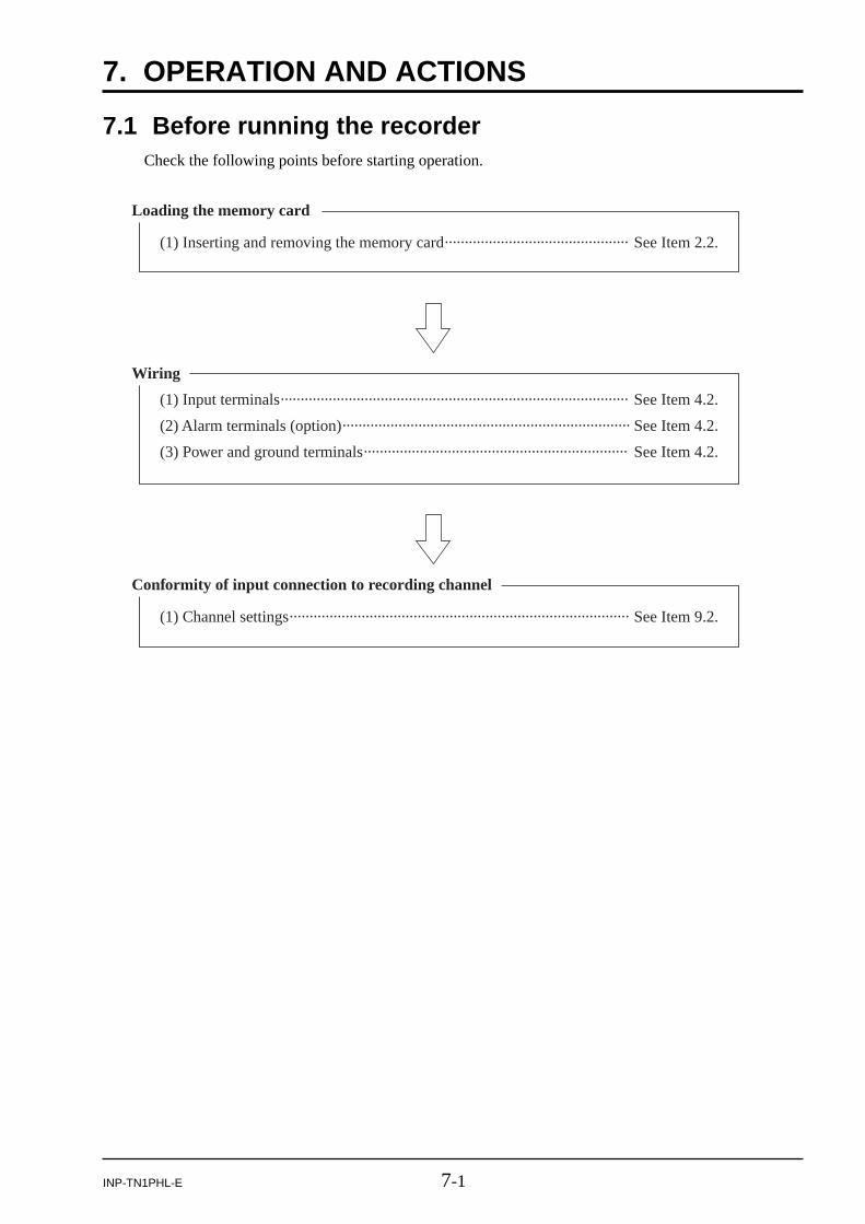
Loading the memory card
(1) Inserting and removing the memory card·············································· See Item 2.2.
Conformity of input connection to recording channel
(1) Channel settings····················································································· See Item 9.2.
Wiring
(1) Input terminals······················································································· See Item 4.2.
(2) Alarm terminals (option)········································································ See Item 4.2.
(3) Power and ground terminals·································································· See Item 4.2.
7.1 Before running the recorderCheck the following points before starting operation.

7-2 INP-TN1PHL-E
Memory card indicatorMemory card load indicator
Measured data for each channel
7.2 Power ON and state(1) Open the panel unit. Turn “ON” the power switch at the upper center of the panel unit.
(2) After power ON, the self-check function starts up.
(3) Insert the memory card. Check if the unit is fixed in the slot, as viewing the memory card loadindicator. When you insert CF card to recorder, see the “Memory card load indicator” and checkthe status of CF card (refer to Item 6.1). If indicator blinks in red, remove the CF card and theninsert again. After this operation, if it keeps on blinking in red, it might be broken.
(4) Measured data are displayed for each channel.
* TAG. No. or the unit display is also available according to screen configuration setting.

7-3INP-TN1PHL-E
ON
Waveforms ofmeasured values
Press
7.3 Stopping and starting the recording operation
(1) Recording start
1) To start the recording, press the key, and password input screen appears. If password hasnot been set, this screen doesn’t appear. Recording password setting parameter, “Record Pass-word” is as shown below.
Menu / Parameter setting / Config and rec password set See Item 9.13 for detail.
Input correct password, then the REC lamp is lighted and measured values are displayed inwaveforms on the data display unit. Also, it starts saving the measured values to the memorycard.
* Recording is performed at the timing described in “Appendix 5 Timing for recording.”
2) When Record password has been established, the following password screen appears. Enter thepassword. If the entered password is correct, the recording is started.
3) If the CF card is not inserted, the following message appears. Press the key to start record-ing. Press the key if you do not want to start recording.
Note: If recording is attempted with CF card not inserted, the result cannot be recorded.

7-4 INP-TN1PHL-E
OFF
Previously recordedwaveforms
Press
(2) Recording stop
1) To stop recording, press the key. The following message appears. To stop the recording,press the key, and press the key to continue recording.
2) After the stop of the recording, the REC lamp comes off. The trend display on the data displayunit stops. In this case, even if there is some data that are not yet written in the memory card, theunit writes them in the card until the recording is finished.
(3) When Record password has been established, the following password screen appears. Enter thepassword. If the entered password is correct, the recording stop confirmation screen appears.
7-5INP-TN1PHL-E
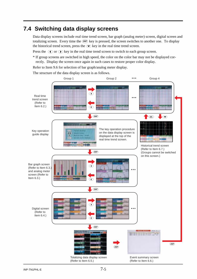
Real time trend screen
(Refer to Item 6.2.)
Key operationguide display
Event summary screen (Refer to Item 6.6.)
Totalizing data display screen (Refer to Item 6.5.)
Historical trend screen (Refer to Item 6.7.) (Groups cannot be switched on this screen.)
The key operation procedure on the data display screen is displayed at the top of the real time trend screen.
Digital screen(Refer to Item 6.4.)
Group 1 Group 2 Group 4
Bar graph screen(Refer to Item 6.3.) and analog meter screen (Refer to Item 6.3.)
7.4 Switching data display screensData display screens include real time trend screen, bar graph (analog meter) screen, digital screen andtotalizing screen. Every time the key is pressed, the screen switches to another one. To displaythe historical trend screen, press the key in the real time trend screen.
Press the or key in the real time trend screen to switch to each group screen.
* If group screens are switched in high speed, the color on the color bar may not be displayed cor-rectly. Display the screen once again in such cases to restore proper color display.
Refer to Item 9.6 for selection of bar graph/analog meter display.
The structure of the data display screen is as follows.

7-6 INP-TN1PHL-E
When an alarm occurs, its content is displayed.
Channel No.
It is indicated that an alarm of alarm No.1and alarm type L occurs at channel 1.
Example of alarm display
Alarm No.
Alarm type
(The display is kept on until the alarm is reset.)
Alarm No.
7.5 Display of alarm
(1) Alarms that occurred on the Trend Display, Bar Graph and Digital Displayscreens:
Note) If an alarm occurs on the “Digital Display” screen, Alarm No. at left of “Measured valuedisplay” is lighted in red.
* If an alarm occurs against the current input, the alarm contents (and not the past alarm record) aredisplayed on the historical screen and the record data display screen of the memory card.

8-1INP-TN1PHL-E
8. SETTING AND CHECKING PARAMETERS
8.1 Setting and checkingFollow the description of Item 8.2 “Outline of parameter setting procedure” to enter into each screen,and then follow the description of Item 8.3 “Basic operation of setting screens” to make parametersetting.
(1) Parameters are factory-set as given in Item 8.1 table(1). Turning on power as they are initiatesoperation (indication and recording). Change the parameter setting as required.
(2) Recording range consists of multi-ranges. Set the range as desired. The input types are the samefor every 2 channels.
(3) Alarms, TAG No. and messages are not set. Set them as needed. An input filter is set at 3 sec-onds.
(4) Press the key in the real time trend display screen to display the “Menu” screen. Refer toItem 8.2 for the contents and the operation of the “Menu” screen.

8-2 INP-TN1PHL-E
(5) To go to “Parameter setting” screen, “CF manager and Totalize exe”. screen or “Calibrationpassword” screen, you must enter 4-digit password when you have already entered each pass-word.
Example: Parameter setting screen
keys : To move the cursor,keys : To change numerical value,
(in case of incorrect password)
(in case of correct password)

8-3INP-TN1PHL-E
Note) After setting the parameters, select “Basic setting” / “Register data” in order to save theset information to a flash memory. To reset parameter set values, press key. So, thefollowing message appears. Press the key twice.The parameter has been reset.

8-4 INP-TN1PHL-E
Parameter nameBasic setting
Setting at delivery (Default value) Setting range Remarks
Channel setting
Display refresh cycle : 1 secondAlarm hysteresis : 0.2%Alarm latch : OFFLCD lights out time : 0DO output at memory FULL: NoneDO output at battery END: NoneMODBUS station No. : 1MODBUS communication baud rate: 19200MODBUS parity bit : OddFront communication : ONRecord data format : ASCIITime setting :
Input type: K-Type TC (K thermocouple)
TAG1: TAG ∗∗ (∗∗: channel No.)TAG2 :Unit : °C
Decimal point position : ∗∗∗∗.∗Input filter : 3 secondsSubtraction channel : NonePV shift : 0.0PV gain : 100%F value calculation function: OFFDisplay color: depends on channel No.Recording type: Maximum/minimum value recordingRecording mode : With recordTotalize setting
Alarm setting
1 second to 12 hoursFrom 0.00 to 100.00%OFF, ON0 to 60 minutes *1
LCD keeps turning on when set “0”.
None, DO1 to DO28None, DO1 to DO280 to 2559600, 19200 bpsNone, Odd, EvenOFF, ONASCII, Binary
Skip, K, E, J, T, R, S, B, N, W, L, U, PN thermocouple, Pt100, JPt100, Ni100, Cu50,Pt50, 50mV, 500mV, 1-5V and 0-5V rangeUp to 8 characters
°C, °F, Engineering unit in case of voltage inputInput range (range start/end): 0 to 1200 Engineering value
0 to 900 seconds (In increments of 1 second)0 to 30 (No subtraction at 0)Engineering value –3276.7 to 3276.70.00 to 327.67%OFF, ON14 colorsInstantaneous value recording, average value recording, maximum/minimum value recordingWith record/Display only
Totalize tag: STAG ∗∗ (∗∗: channel No.)Totalize calculation : OFF
Totalize unit : Totalize cut value : 0.0°CTotalize scaling value: 1
Up to 8 charactersOFF, ON
Totalize type : Periodic Refer to Digital input : DI1 Digital input, Channel alarmTotalize base time : /h /s, /min, /h, /dayReset operation : ON OFF, ON
Can be arbitrarily selectedEngineering value1 to 32767
Set point : 0.0°C Engineering valueOFF, H, L
DO relay No. : NoneFrom alarm No. 2 to No. 4 There are the same items above.
DO1 to DO28
Alarm No. 1 type : OFF
Set the same input type for every 2 channels.
Register data : OFF
*1
Table (1) Parameters as set by factory (initial values) (1/2)

8-5INP-TN1PHL-E
Parameter name
Math timer setting
Setting at delivery (Default value) Setting range Remarks
Display setting
Totalize setting
Message settingOriginal unit definitionDI setting
Constant setting
H-P, L-P timer cycle : 1 minAVG timer cycle : 1 minSUM timer cycle : 1 min
Display configuration: No. 1 to 9 = ch1 to 9
Manual reset : OFFTotalize base time : 00:00Totalize cycle : 1 hourWeekly base day : Sunday
Message : BlankUnit : Blank
Constant : 0
DI function: Function invalid
1 to 32767min1 to 32767min1 to 32767min
No.1 to 10, Each provided with ch1 to 30
OFF, ON00:00 to 23:5910, 20, 30 minutes, 1, 2, 3, 4, 6, 12 and 24 hoursSunday to Saturday
Monthly base day : 1 1 to 31Start time, Stop time: 00:00 to 00:00 00:00 to 23:59External input : DI1 Digital input, Channel alarm
Up to 32 charactersUp to 7 charactersFunction invalid, Rec start/Rec stop, F value calc. reset, Totalize start/stop, Totalize reset,LCD ON-32767 to 32767
F value calculation setting
Config andrecord password
Decimal point position : ∗∗∗∗∗.∗ ∗∗∗∗∗∗, ∗∗∗∗∗.∗, ∗∗∗∗.∗∗, ∗∗∗.∗∗∗, ∗∗.∗∗∗∗
Record Password : 0000 0000 to 9999Password : 0000 0000 to 9999
Math channel setting
Formula setting: All formula are blank Calculation: +, -, ∗, /
Tag1: TAG ∗∗ (∗∗: channel No.)Up to 8 characters
Function: ABS, POW, SQR, LOG, LN, EXP, RH,MAX, MIN, H-P, L-P, AVG, SUMInput: Input channel, Totalizer input, Digital input, Communication input, Constant, Temporay data
TAG2 : BlankUnit : °C
Up to 8 characters
Engineering unit
Input range (range start/end): 0 to 1200 Engineering valueInput filter : 3 seconds 0 to 900 seconds (In increments of 1 second)Subtract channel : None 0 to 30PV shift : 0.0 Engineering valuePV gain : 100.00% 0.00 to 327.67%
Measuring range (range start/end)0.0 to 500.0
Engineering value
Engineering range (range start/end)0.0 to 500.0
Engineering valueDecimal point position : ∗∗∗∗∗.∗ ∗∗∗∗∗∗, ∗∗∗∗∗.∗, ∗∗∗∗.∗∗, ∗∗∗.∗∗∗, ∗∗.∗∗∗∗
Square rooter : OFF OFF, ON
Table (1) Parameters as set by factory (initial values) (2/2)

8-6 INP-TN1PHL-E
Parameter setting
Menu screenReal time trenddisplay screen
CF manager and Totalize exe. menu screen
CF managerpassword set
CF managerpassword set
screen
*1
*3
Version
Record datadisplay screen
Calibration password Calibration password
Record data display
Memory cardabstract screenMemory card abstract
Totalize start/stop screenTotalize start/stop
*2
Input adjustment screen
Other function
Parameter initialization
Input adjustment
Calibration menu screen
Parameter initiali-zation screen
Adjust data initialization
Configrationpassword set
(Note)
(Note)
(Note)
(Note) In case the password has been set.
CF manager password set
CF manager andTotalize exe.
Version displayscreen
Parameter settingmenu screen
Config and recpassword set
Configration password set screen
Basic setting screenBasic setting
Channel setting screenChannel setting
Channel setting copy
Math channelsetting screen
Channel setting copy screen
Math channel setting
Math timersetting screen
Original unit definition screen
Math timer setting
Display setting screenDisplay setting
F value calculationsetting screenF value calculation setting
Totalize setting screenTotalize setting
Message setting screenMessage setting
Original unit definition
Math channel settingcopy screenMath channel setting copy
DI function setting screenDI function setting
Constant setting screenConstant setting
Explanation of key
Important
*1) Parameter setting cannot be changed while recording is in progress.
*2) It is only used for calibration.Don’t use it for otherpurposes.
*3) Parameter setting cannot be changed while integration is in progress.
, keysPressing these keys allow you to shift menus one after another on the “Parameter Set” screen.
keyPressing this key allows you to confirm the menu item on the “Parameter Set” screen.
keyAfter the setting, pressing this key when registering data or canceling data registration returns to the Menu screen.
keyPressing this key in any screen returns to the Real time trend Display screen.
8.2 Outline of parameter setting procedure

8-7INP-TN1PHL-E
8.3 Basic operation of setting screensThe basic operation of the setting screens is classified in the following 3 methods. In this case, use theup and down keys ( and ) to move setting items.
(1) Items to be selected with the or the key
Pressing the or the key switches the blinking between items.
Example: To change the input type from K-Type TC (K thermocouple) to E-Type TC(E thermocouple)
Press the key once.

8-8 INP-TN1PHL-E
(2) To make the setting by entering numeric values
Select a numerical value using the , , t or the s key and then press the key to confirmthe entry.
Example: To select 10°C as the lowest temperature of the setting range
key three times.Press the
key once.Press the

8-9INP-TN1PHL-E
Character entering field
Character display field
(3) To make the setting by entering characters
Select a position in the character entering field you want to enter a character by pressing the t orthe s key, and then press the key.
Select a character in the character display field by pressing the t, s, or the key. Theselected character blinks. Then press the key.
After entering characters in the character entering field, press the key to confirm the entry.
Example: To enter PHL for group screen name
key twelve times.Press the
(Move the cursor to “ENTRY” and then press the [ENT] key.)

9-1INP-TN1PHL-E
9. SETTING PARAMETERS
9.1 Basic setting[Explanation]
Follow the procedure shown below to make basic settings (including display refresh cycle, LCD lightsout time, MODBUS, and current time) of the recorder main unit.
[Operation]
Move the cursor to “Parameter setting” on the Menu screen and press the key, the parrametersetting screen appears. If the password has been set, enter the password.
Move the cursor to “Basic setting” and press the key, the basic setting screen appears.
Display refresh cycle settingAlarm hysteresis settingAlarm latch settingLCD lights out time settingDO setting at the time of memory FULL DO setting at the time of battery ENDMODBUS communication station No. settingMODBUS communication baud rate settingMODBUS communication parity settingMODBUS front communication settingRecord data format settingCurrent time settingRegister of data

9-2 INP-TN1PHL-E
Refresh cycle 1 sec 2 sec 3 sec 5 sec 10 sec 30 sec
Chart speed (as converted) 1296mm/h 648mm/h 432mm/h 260mm/h 130mm/h 43mm/h
20 sec
65mm/h
Refresh cycle 1 min 2 min 3 min 5 min 10 min 30 min
Chart speed (as converted) 22mm/h 11mm/h 7.2mm/h 4.3mm/h 2.2mm/h 0.7mm/h
20 min
1.1mm/h
Refresh cycle 1 hour 2 hours 3 hours 4 hours 6 hours
Chart speed (as converted) 0.36mm/h 0.18mm/h 0.12mm/h 0.09mm/h 0.06mm/h
12 hours
0.03mm/h
(1) To set display refresh cycle
Move the cursor to “Refreshment cycle” and press the key, then the cycle time screen shownbelow appears.
(Cycle time: 1, 2, 3, 5, 10, 20, 30 seconds,1, 2, 3, 5, 10, 20, 30 minutes, 1, 2, 3, 4, 6, and 12 hours)
The first time of the display update is started from 00:00:00 of the following without fail.
(Example)
When refresh cycle is set to 1 min, the next cycle begins at hh : mm : 0 (sec).
Note) If the refresh cycle time is short and a large number of recording files exist, therecording at every refresh cycles may be skipped. Recording files should belimited to 100 or less.
Relationship between “Refresh cycle” and “Chart speed” (on screen) is given below.

9-3INP-TN1PHL-E
(2) To set the alarm output hysteresis width
Move the cursor to “Alarm hysteresis” and press the key. The alarm hysteresis screenappears (as shown below). Enter hysteresis width (0 to 100%) by the cursor key and then pressthe key for confirmation. It is applicable to all types of alarms. The numeric value is ex-pressed as a percentage of the display range for each channel.
(3) To set alarm latch
Move the cursor to “Alarm latch” and press the key, then the alarm latch setting screenappears. Make the setting using the cursor key and press the key.
Alarm latch function keeps alarm output turning on even after the cause of the alarm has beenremoved. To cancel the alarm latch, select it to OFF. Alarm cancel is recorded in the eventsummary in this case.
(4) To enter LCD lights out time
Move the cursor to “LCD-lights out time” and press the key, then the LCD lights out timesetting screen appears.
Make the setting (0 to 60 minutes) using the cursor key and press the key.
The LCD is kept on at all times by entering 0 minute.
* Press any key to turn on the LCD.
(5) To make DO setting at the time of memory FULL
Move the cursor to “Memory full alarm” and press the key, then the DO output setting screenappears. Select desired DO output No. using the cursor key and press the key.
DO output works when memory FULL is detected. Select “None” not to use this function.
Note) DO11 to 28 are open collector outputs and not relay outputs.
Note) “Memory full alarm” is turned on when the remaining memory reaches 0%. Thisvalue cannot be set.
Note) When memory card is removed, DO output turns off. But the message of memorycard full does not appear. Press the or key, it appears.

9-4 INP-TN1PHL-E
(6) To make DO setting at the time of battery END
Move the cursor to “Battery alarm” and press the key, then the DO output setting screenappears.
Select desired DO output No. using the cursor key and press the key.
DO output functions when the battery END is detected. Select “None” not to use the function.
When battery END is detected, a message is displayed on the trend screen.
Note) DO11 to 28 are open collector outputs and not relay outputs.
(7) To select a station No. for MODBUS communication
Move the cursor to “MODBUS station No.” and press the key, then the station No. settingscreen appears.
Select desired RS-485 MODBUS station No. (0 to 255) using the cursor key and press the key. When set 0 to this parameter, communication does not work.
(8) To select baud rate for MODBUS communication
Move the cursor to “MODBUS baud rate” and press the key, then the baud rate settingscreen appears.
Select desired RS-485 MODBUS communication baud rate (from 9600 and 19200 bps) using thecursor key and press the key.
(9) To select parity bit for MODBUS communication
Move the cursor to “MODBUS parity” and press the key, then the parity bit setting screenappears.
Select desired RS-485 MODBUS parity bit (from None, Odd and Even) using the cursor key andpress the key.
(10) To select front communication setting (for loader)
Move the cursor to “Front communication” and press the key, then the front communicationsetting screen appears.
Select “ON” when this recorder is connected to a loader cable.
(11) To set record data format
Move the cursor to “Record data format” and press the key, then the data format settingscreen appears.

9-5INP-TN1PHL-E
Reference 1: The clock is set to the current time of Japan Standard Time by the factoryat shipment.Since it is backed-up by a lithium-ion battery, it is always running withpower interruption or power OFF. The lithium battery has a service life ofabout 10 years at normal temperature of 25°C.
Reference 2: The time scale is divided into 24 hours. The range is set from 00: 00 to23: 59.
Reference 3: A “second” is not settable. But, the inside of the clock is treated as follows.After setting the “minute”, press the key at the “Adjust” position. Then,the clock runs with the second counter set to 0.
(12) To select time
Move the cursor to “Time setting” and press the key, then the time setting screen appears.
Select desired time, year, month, hour and minute, using the cursor key and press the key.
(13) Registering method of set values (saving to flash memory)
Move the cursor to “Register data” and press the key, PHL registers the set value to the flashmemory.
Note 1) When the parameter memory lamp blinks in red, it indicates that set parametersare not registered to the flash memory. Operate in accordance with above (13) toregister to flash memory.
Note 2) After parameters have been set, operate in accordance with above (13). Otherwise,the set values returns to original values when turning OFF power.
Select either ASCII or Binary as data recording format.
Each format has the following characteristics.
ASCII format
• Allows the recorded data to be opened directly on Excel or using text editor.
• The number of data that can be recorded is relatively small (approximately 1/4 of those recordedin binary format)
Binary format
• The recorded data cannot be opened directly on Excel or using text editor.
The recorded data can be opened using the attached data viewer software, and then by convert-ing it to CSV file, it can be opened on Excel or the using text editor.
• The number of data that can be recorded is relatively large (approximately 4 times of thoserecorded in ASCII format).

9-6 INP-TN1PHL-E
9.2 Channel settings[Explanation]
Follow the procedure shown below to select input type, unit, scaling, input filter (time constant),PV shift, PV gain, subtraction, F value calculation, color, TAG No., recording type, recording mode,totalizing setting and alarm setting for each channel.
[Operation]
Move the cursor to “Parameter setting” on the Menu screen and press the key. If the passwordhas been set, enter the password, and the parameter setting screen appears.
Move the cursor to “Channel setting” and press the key, then channel setting screen appears.
On this screen, select desired channel number and press the key. Following screen appears.
Input type settingTAG No. setting
Scaling settingUnit settingMeasurement range setting
Decimal point position settingEngineering value setting
Square root calculation setting
Display range settingInput filter settingSubtraction channel settingPV shift value settingPV gain settingF value calculation function settingDisplay color settingRecording type settingRecording mode settingTotalizing settingAlarm setting

9-7INP-TN1PHL-E
(1) To set input type
Move the cursor to “Input type” and press the key, then the following input type selectionscreen appears. Select any input signal by using the cursor key and press the key. If youdon’t want to perform “indication”, “recording”, and “alarm” operation, select “Skip”.
Note 1) When the “Input type” is set to “Skip”, indication, recording and alarm for thechannel are not carried out.
Note 2) After the change of the “Input type”, wait for a while until the measured valuestabilizes.
Note 3) When the recorder is in recording, the “Input type” cannot be changed.
Input type Details
Thermocouple, 50mV
Resistance bulb Pt100, JPt100, Ni100, Pt50, Cu50
K, E, J, T, R, S, B, N, W, L, U, and PN thermocouples, 50mV
500mV 500mV
5V 1 to 5V, 0 to 5V
Note) About input type setting
Basically, the input type can be every 2 channels.
The input type of channel 2, 4, 6, 8, 11, 13, 15 and 17 can only be set in the same category ofprevious channel.
If “Skip” has been selected for the previous channel, arbitrary input type can be selected.
The following input types are available.
Note, however, that arbitrary input type can be selected only for channels 9 and 18 irrespectiveof the type allocated to other channels. For example, if the input type 1 to 5V is selected forchannel 1, the following screen appears as the input type selection screen for channel 2, whichallows only1 to 5V, 0 to 5V, or Skip to be selected.

9-8 INP-TN1PHL-E
Input type DescriptionInput type
Channel 1 K thermocouple Thermocouple, 50mV The type of thermocouple can be arbitrarily selected for each channel.Channel 2 T thermocouple
Channel 3 1 to 5V 5V
Channel 4 0 to 5V
Channel 5 Pt100 Resistance bulb The type of resistance bulb can be arbitrarily selected for each channel.Channel 6 JPt100
Channel 7 500mV 500mV
Channel 8 500mV
Channel 9 J thermocouple Thermocouple, 50mV Input type can be arbitrarily selected for channel 9.
Channel 10 K thermocouple
Channel 11 50mV
Thermocouple, 50mV The input type of the thermocouple and 50mV is the same.
Channel 12 Skip
Channel 13 1 to 5V
5V Skip can arbitrarily selected irrespective of the input type.
Channel 14 Pt100
Channel 15 Skip
Resistance bulb
Channel 16 Skip
Channel 17 500mV
500mV
Thermocouple, 50mV Input type can be arbitrarily selected for channel 18.Channel 18 50mV
The sample of input type setting

9-9INP-TN1PHL-E
(2) To set TAG 1 and TAG 2
• TAG 1Move the cursor to “Tag 1” and press the key, then “TAG Setting” screen appears as shownbelow. Enter the TAG name by using the cursor key and press the key for confirmation.After entry of the TAG name, press the key to register the data.
Up to 8 characters can be entered. Note, however, that on some screens such as trend screen, only7 characters can be displayed.
• TAG 2Tag 2 is displayed on the screen for 4 channels.To display at the TAG display area on trend display screen is selectable by parameter, “Channelindex”.Regarding to setting method, refer to 9.6 (7), “To select channel index”.
(3) To set scaling
With DC voltage input, set scaling “ON” “OFF” with the cursor key.
Note) When scaling is set to “ON”, the recording range is zero-cleared. For details, refer toItem 9.2 (9) “To set display range”.
(4) To set units
Units can only be set when the scaling is set to “ON”.
Move the cursor to “Unit” and press the key, then “Unit menu” screen (below) appears.Select any unit on the screen by using the cursor key, and press the key.
Unit select screen varies depending on the input type. (The following figure is the case of DCvoltage input.)

9-10 INP-TN1PHL-E
(5) To enter the measuring rangeThe measuring range can be set only when the scaling is set to ON at voltage input type.To display the measuring range setting screen, move the each cursor to “Measuring start” or“Measuring end” and press the key. Enter the measuring range by using the cursor key andpress the key for confirmation.“Measuring start” means low limit, while “Measuring end” means high limit.
Temperature· humidity
°C
°F
%RH
vol%
Flow rate
t/d
kg/d
g/d
m3/d
l/d
t/h
kg/h
g/h
m3/h
l/h
t/min
kg/min
g/min
m3/min
l/min
t/s
kg/s
g/s
m3/s
l/s
Pressure
mbar
bar
N/mm2
N/m2
mPa
Pa
kPa
MPa
Level·Height
mm
cm
m
Capacity · Weight · Area
ml
l
kl
mm3
cm3
m3
mm2
cm2
m2
g
kg
t
Density
g/cm3
kg/cm3
g/m3
kg/m3
Analysis
g/l
kg/l
g/ml
ppm
ppmNH3
ppmSO2
ppmH2S
ppmCO
ppmO2
ppmNOx
ppb
pH
mol
%
%H2
%CO2
%He
%Ar
%O2
%NaCl
%CO
Power · Acceleration
mN
N
N · m
J
kJ
mm/s
mm/min
mm/h
m/s
m/min
m/h
m/s2
rad/s
km/h
Time Electro-magnetism
rps
rpm
rph
µs
ms
s
min
h
day
mV
V
kV
µA
mA
A
Electromagnetism
Hz
dB
W
kW
Heat · Light
Var
kVar
µS/cm
µF
F
C
VA
kVA
mH
H
m ohm
ohm
k ohm
M ohm
(Unit 1)
(Unit 2)
(Unit 3)
(Unit 4)
(Unit 5)
(Unit 6)
(Unit 7)
(Unit 8)
(Unit 9)
(Unit 10)
(Unit 11)
(Unit 12)
lx
cd
lm
cd/m2
µSv/h
mSv/h
nGy/h
µGy/h
µm
OtherRadiation
Pa · s
mPa · s
Customer-made(Note 2)
Unit code
Note 1) Blank consists of some spaces
Note 2) Units can be made by the customer (See Item 9.10).
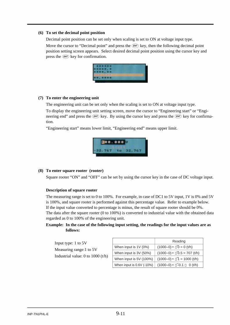
9-11INP-TN1PHL-E
(8) To enter square rooter (rooter)
Square rooter “ON” and “OFF” can be set by using the cursor key in the case of DC voltage input.
Description of square rooter
The measuring range is set to 0 to 100%. For example, in case of DC1 to 5V input, 1V is 0% and 5Vis 100%, and square rooter is performed against this percentage value. Refer to example below.If the input value converted to percentage is minus, the result of square rooter should be 0%.The data after the square rooter (0 to 100%) is converted to industrial value with the obtained dataregarded as 0 to 100% of the engineering unit.
Example: In the case of the following input setting, the readings for the input values are asfollows:
When input is 1V (0%) (1000-0) × √–0 = 0 (t/h)
When input is 3V (50%) (1000-0) × √–0.5 = 707 (t/h)
When input is 5V (100%) (1000-0) × √–1 = 1000 (t/h)
When input is 0.6V (-10%) (1000-0) × √–-0.1 → 0 (t/h)
Reading
(6) To set the decimal point position
Decimal point position can be set only when scaling is set to ON at voltage input type.
Move the cursor to “Decimal point” and press the key, then the following decimal pointposition setting screen appears. Select desired decimal point position using the cursor key andpress the key for confirmation.
(7) To enter the engineering unit
The engineering unit can be set only when the scaling is set to ON at voltage input type.
To display the engineering unit setting screen, move the cursor to “Engineering start” or “Engi-neering end” and press the key. By using the cursor key and press the key for confirma-tion.
“Engineering start” means lower limit, “Engineering end” means upper limit.
Input type: 1 to 5V
Measuring range:1 to 5V
Industrial value: 0 to 1000 (t/h)

9-12 INP-TN1PHL-E
(9) To set display range
Move the each cursor to “Range start” or “Range end” and press the key, then, the “Rangesetting” screen appears as shown below. Enter the range by the cursor key, and press the keyfor confirmation.
For the setting range, refer to Table 1, “Display Range Set Range”.
Type
DC voltage
Thermocouple BRSKEJTNWLU
PN
Resistancebulb
JPt100Pt100Ni100Pt50Cu50
400 to 1760°C0 to 1760°C0 to 1760°C
–200 to 1370°C–200 to 800°C–200 to 1100°C–200 to 400°C
0 to 1300°C0 to 1760°C
–200 to 900°C–200 to 400°C
0 to 1300°C
–200 to 600°C–200 to 600°C–60 to 180°C
–200 to 600°C–50 to 200°C
Input range Record range set range
0 to + 50mV0 to +500mV
+ 1 to + 5V 0 to + 5V
370.0 to 1790.0°C– 30.0 to 1790.0°C– 30.0 to 1790.0°C–230.0 to 1400.0°C–230.0 to 830.0°C–230.0 to 1130.0°C–230.0 to 430.0°C– 30.0 to 1330.0°C– 30.0 to 1790.0°C–230.0 to 930.0°C–230.0 to 430.0°C– 30.0 to 1330.0°C
–230.0 to 630.0°C–230.0 to 630.0°C–90.0 to 210.0°C
–230.0 to 630.0°C–80.0 to 230.0°C
– 10.00 to + 55.00mV– 10.0 to + 550.0mV+ 0.500 to + 5.500V – 0.100 to + 5.500V
Table 1 Display Range Set Range
<in case of input type is thermocouple or Pt> <in case of input type is voltage input>

9-13INP-TN1PHL-E
(10) To set input filter (primary delay filter)Move the cursor to “Input filter” and press the key, then small window appears. Selectnumerical values by using the cursor key.
Input filter range: 0 to 900 sec (step of 1 sec)
(11) To select subtraction channel
Move the cursor to “Subtract channel” and press the key, then small window appears. Selectthe channel No. for which subtraction is to be performed using the cursor.
[Subtraction function]
• The result of subtraction of the values for 2 channels is recorded to the channel to be set.
Example: When the result of ch1-ch2 is recorded to ch1
ch1=ch1-ch2
• Be sure to perform subtraction between the channels having the same unit and decimal point posi-tion. Otherwise the record cannot be guaranteed.
• Subtraction is not performed when “none” is selected.
• Limit doesn’t work for the result of subtraction.

9-14 INP-TN1PHL-E
(12) To set PV shift value
Move the cursor to “PV shift” and press the key, then “PV shift” screen appears as shownbelow.
Enter PV shift value by using the cursor key and press the key.
• Shift calculation
Recorded and displayed value
Recorded and displayed value
(Measured values after PV calculation)
Measured values
Shift setting = 10
Shift setting of 0
• Gain calculation
(Measured values after PV calculation)
Measured values
Gain setting = 110%
Gain setting of 100%
[PV shift function]
• Measured values can be calculated, recorded, and displayed with the PV shift constant.
• PV shift calculation can be achieved with the gain and shift values.
Conversion graphs relating to shift calculation and gain calculation are shown below.
• PV shift is calculated as follows;
P’ = AP + B
Where,
P’: Measured value after calculation of PV shift
P : Measured value
A : Gain (0.00 to 327.67%)
B : Shift values (setting range: –32767 to 32767 engineering unit, decimal pointdepends on input type)
* The measured value after PV shift calculation is limited so that it falls within the settablerecord range by input type set for each channel. The judgement of input error (such asBurnout, Error, and Over) is performed against the input and not for the result of shift or gaincalculation.
• If input type is changed or the scaling function is turned ON/OFF, the PV shift set value for thechannel is cleared. (If the scaling function is turned ON/OFF by the setting copying function, the PVshift set value for the channel is not cleared.)
• The Copy function allows you to copy set values, but it is not provided with a means of making copyof PV shift set values.

9-15INP-TN1PHL-E
(13) To set PV gainMove the cursor to “PV gain” and press the key, then the “PV gain” screen appears as shownbelow.
Enter PV inclination by using the cursor key and press the key.
(14) F value calculation functionSelect F value calculation “ON” or “OFF” using the cursor.Note that if “ON” is selected, calculation is performed according to the selection made in Item 9.7“Setting method of F value calculation.”
[F value calculation function]
From the measured temperature, the extinction value of bacteria by sterilization by heating can becalculated.
F value calculation formula
6010 Z
(T – T0)
F value =
T : Measured temperatureT0 : Reference temperatureZ : Z value
• F value calculation is performed by the second.
• The measured temperature of the channel for which F value calculation is performed cannot berecorded.
• The unit field of the channel for which F value calculation is performed is kept blank, and thedecimal place is set to the one designated in F value calculation setting screen that is common toall channels.
• The constants to be used for F value calculation (reference temperature, Z value, and decimalpoint position) are common to all channels.
• F value calculation can be reset manually or by DI or temperature setting.
• If input is abnormal, an error (such as Over, Under, Burnout, Error) is displayed, but 0 is re-corded.

9-16 INP-TN1PHL-E
(15) To set display colorMove the cursor to “Color” and press the key, then the following color selection windowappears. Select the display color using the cursor and press the key.
(16) To set recording typeMove the cursor to “Recording type” and press the key, then the following recording typeselection screen appears. Select a desired recording type using the cursor key, and then press the
key.
[About recording type]
Recording type can be selected from the following three.
• Point value recording: Records the instantaneous measurement value at every display refreshcycle.
• Average value recording: Records the average measurement value during the display refreshcycle at every display refresh cycle.
• Maximum/minimum recording: Records the maximum/minimum measurement value during thedisplay refresh cycle at every display refresh cycle.
* Longer recording is allowed with instantaneous and average value recording than with maxi-mum/minimum value recording.
(17) To set recording modeMove the cursor to “Recording mode” and press the key, then recording mode screen ap-pears.Select either “With record” or “Display only” by the cursor.
When setting “Display only”, trend display on the Trend screen and history display on the Histori-cal screen are not carried out. Further, nothing is recorded except for display of measured values.

9-17INP-TN1PHL-E
(18) Totalize settingMove the cursor to “Totalize setting” and press the key, then the following totalizing settingscreen appears.
Select the item to be set using the cursor key and then press the key.
(a) To set totalize tag
Move the cursor to “Totalize tag” and by press the key, then the following character entryscreen appears. Enter the tag name by using the cursor key and press the key. When entry iscompleted, press the key to register the entry.
• Totalize tag is recorded in totalize recording result and displayed on the totalize display screen.
Totalize tag settingTotalize calculation setting
Totalize data unit settingTotalize cut value settingTotalize scaling value setting

9-18 INP-TN1PHL-E
(b) To set totalize calculation
Either “Totalizer,” “Counter,” or “Timer” can be selected as “Totalize calculation.”
a) Select “Totalizer” to perform totalize function of creating daily and monthly reports.
b) Select “Counter” to record the number of times of DI ON or alarm ON during the totalizeperiod. The value to the right of decimal point is discarded.
c) Select “Timer” to record the duration of DI ON or alarm ON during the totalize period.
In all of the above cases, time is displayed based on the time set in a parameter, “Totalizebase time,” with all digits to the right of the decimal point discarded.
(c) To set totalize type
Select one from daily report, weekly report, monthly report, annual report, continuous totalizing,and daily report (at designated time) in “Totalize type.” Refer to the following table for thetotalize operation of each selection.
Periodic report
Daily report
Weekly report
Monthly report
Annual report
Daily report (at designated time)
External input
Totalized value is recorded (and reset) at every totalize cycle that has been set. The totalize cycle is from one totalize base time to another.
Totalized value is recorded (and reset) at totalize base time every day.
Totalized value is recorded (and reset) weekly at totalize base time of the specified day of the week.
Totalized value is recorded (and reset) monthly at totalize base time of the specified day of the month.
Totalized value is recorded (and reset) annually at totalize base time on January 1st.
Totalizing is performed from the start time to the stop time every day, and on completion of the operation, totalized value is recorded (and reset).
Totalize operation is performed during the period from the external input is turned on to it is turned off. Totalized value is recorded (and reset) when it is turned off.
(Totalize calculation is not reset even if the power is turned off.)
(d) To set digital input
• Use DI input for totalizing when “Counter” or “Timer” is specified for totalize calculation.
* Since Digital input is Di2 in this example, it is independent of the on/off operation of Di1.
Example: When the following parameters are selected, data is recorded as shown below.
Di1 OFF OFF
Recorded data
OFFON ON
Di2 OFF OFF OFFON
10
ON
Totalize base time = /minTotalize type = DairyDigital input = Di2
20 30 40 50 60Totalize start Elapsed time [min]
[min]
Totalize calculation = Counter
= Timer
1
0
1
10
2
10
2
20
2
30
2
30

9-19INP-TN1PHL-E
(e) To set totalize base time
• Totalize base time can be selected from /s, /min, /h, and /day.
Example: If the flow rate is 120L/min, totalized value for each totalize base time appears as follows.
Totalize reset
Elapsed time OFF ON
1 hour 100 100
2 hours 200 100
3 hours 300 100
Base time /s /min /h /day
Totalized value 2 120 7,200 172,800
* Flow rate of 120L/min is also expressed as 2L/s (120/60), or 7,200L/h (120×60).
(f) To set reset operation
• If “Reset Operation” setting is ON, totalize data is recorded in the totalize file at every totalizecycle.
• If “Reset Operation” setting is OFF, sum total data from the start of totalizing is recorded in thetotalize file.
Example: If the flow rate is 100L/h, the record data appears as follows.
(g) To set totalize unit
Move the cursor to “Totalize unit” and press the key to display the following unit selectscreen. Select the desired unit using the cursor key and then press the key.

9-20 INP-TN1PHL-E
(h) To set totalize cut value
Move the cursor to “Totalize cut value” and press the key to display the following totalizecut value setting screen. Enter totalizing cut value using the cursor and the key.
• If the measured value is smaller than the totalizing cut value, the measured value is regarded as0 in the totalizing (totalizing value does not increase).
(i) To set totalize scale value
Move the cursor to “Totalize scale value” and press the key, and the following totalizescaling setting screen appears.
Enter the scaling value using the cursor key and press the key.
• Specify as “Totalize scale value” the scale conversion value used to convert the input value tototalized value. Division only is allowed. Multiplication cannot be performed.
Totalize value = Analog input/Totalize scale value
Example: To convert the unit of input value (L/h) to [m3/h],
1 [L/h] =1/1000 [m3/h]
Totalize scale value = 1000
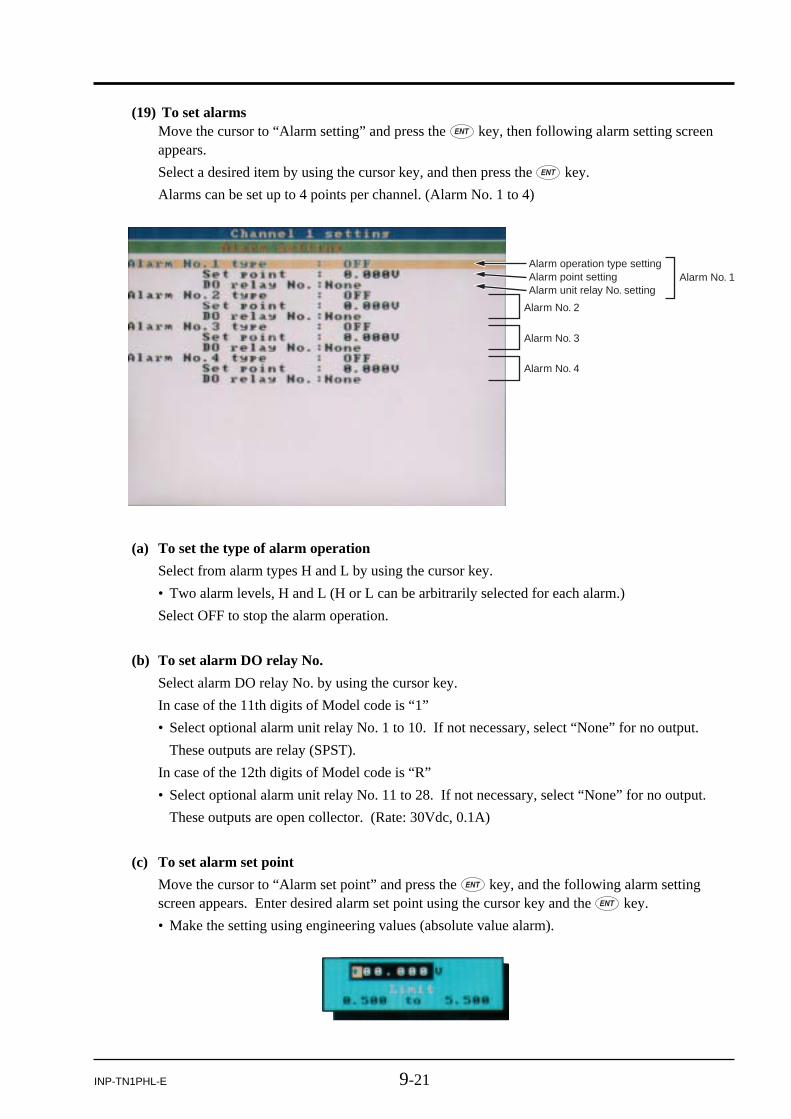
9-21INP-TN1PHL-E
(19) To set alarmsMove the cursor to “Alarm setting” and press the key, then following alarm setting screenappears.
Select a desired item by using the cursor key, and then press the key.
Alarms can be set up to 4 points per channel. (Alarm No. 1 to 4)
Alarm operation type settingAlarm point settingAlarm unit relay No. setting
Alarm No. 2
Alarm No. 3
Alarm No. 4
Alarm No. 1
(a) To set the type of alarm operation
Select from alarm types H and L by using the cursor key.
• Two alarm levels, H and L (H or L can be arbitrarily selected for each alarm.)
Select OFF to stop the alarm operation.
(b) To set alarm DO relay No.
Select alarm DO relay No. by using the cursor key.
In case of the 11th digits of Model code is “1”
• Select optional alarm unit relay No. 1 to 10. If not necessary, select “None” for no output.
These outputs are relay (SPST).
In case of the 12th digits of Model code is “R”
• Select optional alarm unit relay No. 11 to 28. If not necessary, select “None” for no output.
These outputs are open collector. (Rate: 30Vdc, 0.1A)
(c) To set alarm set point
Move the cursor to “Alarm set point” and press the key, and the following alarm settingscreen appears. Enter desired alarm set point using the cursor key and the key.
• Make the setting using engineering values (absolute value alarm).

9-22 INP-TN1PHL-E
9.3 Copying parameters[Explanation]
Parameters can be copied to other channels.
Parameters that can be copied are input type, input filter, scaling, recording range, unit, TAG No.,alarm setting, and subtraction channel.
[Operation]
Select the “parameter setting” on the menu screen and enter the password if the configuration pass-word has been set, then select “Channel setting copy”. After that, following “channel setting copy”screen appears.
Copy screen used when the number of input points is 9
Channel No. to copy from
Channel No. to paste to
When parameters are pasted to all channels
Copy start button
(1) Channel No. to copy fromSelect a channel No. from which parameters are to be copied using the cursor key. Then pressthe key, and following channel selection screen appears.
(2) Channel No. to paste toSelect the channel No. to which parameters are to be pasted using the cursor key and press the
key. If you want to cancel, press the key.(When you want to paste to all the channels, select “All channels.”)
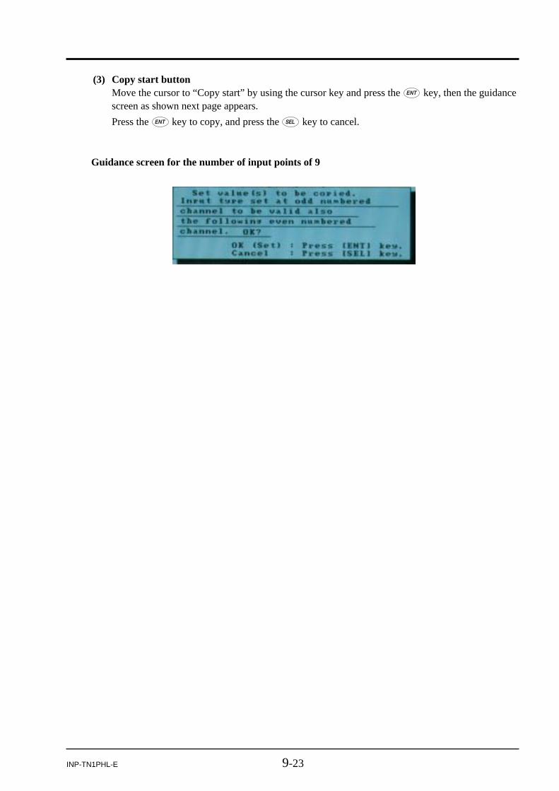
9-23INP-TN1PHL-E
Guidance screen for the number of input points of 9
(3) Copy start buttonMove the cursor to “Copy start” by using the cursor key and press the key, then the guidancescreen as shown next page appears.
Press the key to copy, and press the key to cancel.

9-24 INP-TN1PHL-E
9.4 Setting calculation function[Explanation]
Twelve channels from Channel 19 to 30 can be used as calculation channels.
(a) Three operations × 4 formulas can be set for each channel.
The result of Formula 4 is input to the operation channel.
The result of operation is limited to ±32767 with all digits to the right of the decimal point dis-carded.
(b) Note 1: Arithmetic operations are performed from left to right without fail.
Example: Formula 1, B01 = C01 + C02 × C03, is calculated as B01 = (C01 + C02) × C03.
Note 2: AVG(A) and SUM(A,B) can be used only once for each channel.
Note 3: It takes a long time to perform many arithmetic operations, and consequently the displaycycle of measurement may become long.
Refer to the following table for the functions used for calculation.
Operation Grammar Description
Arithmetic operation (addition) A+B Adds the value of input A and input B.
Arithmetic operation (subtraction)
A-B Subtracts the value of input B from input A.
Arithmetic operation (multiplication)
Multiplies the value of input A by input B.A B
Arithmetic operation (division) A/B Division the value of input A by input B.Note: The result of calculation of 0/0 is 0.
Power
ABS(A) Finds the absolute value of input A.Absolute value
POW(A,B) Finds the value of input A to the power input B. (A B)
Square root SQR(A) Finds the square root of the value of input A.
EXP
LOG(A) Finds the common logarithm of the value of input A.LOG
LN(A) Finds the natural logarithm of the value of input A.LN
EXP(A) Finds the exponentiation of the value of input A with base “e.”
Humidity RH(A,B) Finds the relative humidity when input A represents dry-bulb temperature and input B represents wet-bulb temperature.
Maximum (between channels) MAX(A,B) Finds the maximum value from inputs A and B.
Minimum (between channels) MIN(A,B) Finds the minimum value from inputs A and B.
Maximum (time) H-P(A) Finds the maximum value of input A. Initializes the maximum value by timer input.
Minimum (time) L-P(A) Finds the minimum value of input A. Initializes the minimum value by timer input.
Average AVG(A) Finds the average value of input A. Refreshes the average value by timer input.
Clear the formula END/Delete Clear the formula without confirming. Be careful not to missoperate. You can’t cancel this operation.
Set the soarce Math data Set the sorce from “Input channel”, “Totalizer input”, “Digital input”, “Communication input”, “Constant” or “Temporary formula”.
Summatio SUM(A,B) Finds the sum of input A/B. Resets the sum by timer input

9-25INP-TN1PHL-E
(c) The input point that can be used for calculation are as follows.
Input Grammar Description
Input channel C01 to C30 Channel 1 to 30 input
Totalize input T01 to T30 Channel 1 to 30 totalize (The totalized value limited to ±32767 with all digits to the right of the decimal point discarded is used.)
Digital input DI1 to 10 (OFF: 0, ON: 1)D01 to D10
Communicationn input M01 to M12 1 to 12 (No decimal fraction allowed.)
Temporary formula
K01 to K20 1 to 20Constant
B01 to B03 1 to 3
Detailed description of functions
ABS(A) : Finds the absolute value of input A
Example of output of ABS(A) is shown below. (The decimal place of operation channel is 1.)
10.0 10.0
InputA
OutputABS (A)
Memo
-10.0 10.0
POW(A,B) : Finds the value of input A to the power input B. (A**B)
If negative fractional value is raised to the power of a fractional value, 0 is output.
The result of 0 raised to the power of 0 is 1.00
Example of output of POW(A) is shown below. (The decimal place of operation channel is 1.)
50.0 2500.0
InputA
OutputPOW (A, B)
Memo
0.0 1.0
2.0
-5.5 0.0
The result of 0 raised to the 0th power is 1.
When erroneous data is input.2.5
InputB
0.0
SQR(A) : Finds the square root of the value of input A.
If negative data is input, 0 is output.
Example of output of SQR(A) is shown below. (The decimal place of operation channel is 1.)
100.0 10.0
InputA
OutputSQR (A)
Memo
-10.0 0.0 If negative data is input, 0 is output.
LOG(A) : Finds the common logarithm of the value of input A.
If negative data is input, 0 is output.
Example of output of LOG(A) is shown below. (The decimal place of operation channel is 1.)
100.0 2.0
InputA
OutputLOG (A)
Memo
-10.0 0.0 If negative data is input, 0 is output.

9-26 INP-TN1PHL-E
LN(A) : Finds the natural logarithm of the value of input A.
If negative data is input, 0 is output.
Example of output of LN(A) is shown below. (The decimal place of operation channel is 1.)
100.0 4.6
InputA
OutputLN (A)
Memo
-10.0 0.0 If negative data is input, 0 is output.
EXP(A) : Finds the exponentiation of the value of input A with base “e”. (e**A)
Example of output of EXP(A) is shown below. (The decimal place of operation channel is 1.)
1.2 3.3
InputA
OutputEXP (A)
Memo
RH(A,B) : Finds the relative humidity when input A represents dry-bulb temperature and inputB represents wet-bulb temperature.
The temperature range that allows the calculation of humidity is from -40 to +150°C.
If the wet-bulb temperature is equal to or higher than the dry-bulb temperature, 100%RH isoutput.
If the temperature is outside the measurable range, the values in the following table areoutput.
Dry-bulb temperature
Wet-bulb temperature
Lower than -40°CWithin the range
Higher than +150°C
0%RH
0%RH
0%RH
0%RH
Calculated value
100%RH
0%RH
Lower than -40°C Within the range Higher than +150°C
100%RH
100%RH
Example of output of RH(A,B) is shown below. (The decimal place of operation channel is 1.)
70.0 79.2
Input A (Dry-bulb temperature)
OutputRH (A, B)
Memo
50.0 0.0
65.0
70.5 100.0
Input B < -40°C100%RH is output if input A = Input B.70.0
Input B (Wet-bulb temperature)
-41.0
151.0 100.0 Input A > 150°C10.0
MAX(A,B) : Finds the maximum value from inputs A and B.
Example of output of MAX(A,B) is shown below. (The decimal place of operation channel is 1.)
50.0 50.0
InputA
OutputMAX (A, B)
Memo
49.0
49.0 50.0 Input A < Input B
Input A > Input B
50.0
InputB

9-27INP-TN1PHL-E
MIN(A,B) : Finds the minimum value from inputs A and B.
Example of output of MIM(A,B) is shown below. (The decimal place of operation channel is 1.)
50.0 49.0
InputA
OutputMIN (A, B)
Memo
49.0
49.0 49.0 Input A < Input B
Input A > Input B
50.0
InputB
H-P(A) : Finds the maximum value of input A.
The output is initialized in a cycle established as H-P, L-P timer cycle.
Example of output of H-P(A) is shown below. (The decimal place of operation channel is 1, and H-P,L-P timer cycle is 2 minutes.)
50.0 Maximum sine wave value
Input A
Sine wave cycle: 1 minute, Amplitude: 50.0, Bias: 0.0
Output H-P(A) (Output value per cycle)
Memo
L-P(A) : Finds the minimum value of input A.
The output is initialized in a cycle established as H-P, L-P timer cycle.
Example of output of L-P(A) is shown below. (The decimal place of operation channel is 1, and H-P,L-P timer cycle is 2 minutes.)
-50.0 Minimum sine wave value
Input A
Sine wave cycle: 1 minute, Amplitude: 50.0, Bias: 0.0
Output L-P(A) (Output value per cycle)
Memo
AVG(A) : Finds the average value of input A.
The average value during the cycle established as AVG timer cycle is output.(Display is not changed during the cycle.)
Example of output of AVG(A) is shown below. (The decimal place of operation channel is 1, and theAVG timer cycle is 2 minutes.)
0.0 Average sine wave value
Input A
Sine wave cycle: 1 minute, Amplitude: 50.0, Bias: 0.0
Output AVG(A) (Output value per cycle)
Memo
SUM(A) : Finds the sum of input A/B.
The totalized value is reset in the cycle established as the SUM timer cycle.Negative values can also be totalized.
Example of output of SUM(A) is shown below. (The decimal place of operation channel is 1, and theSUM timer cycle is 2 minutes.
50.0 50.0
Input A (Fixed)
OutputSUM (A, B)
Memo
-50.0 -50.0
120.0
50.0 100.060.0
Input B (Fixed)
120.0

9-28 INP-TN1PHL-E
(1) Formula settingMove the cursor to “Formula setting” and press the key, and the following formula settingscreen appears.
[Operation]
Select the “parameter setting” on the menu screen and enter the password if the configuration pass-word has been set, then select “Math channel setting” and desired channel number. After that, follow-ing channel number setting screen appears. Press the key.
Formula setting
Decimal point position setting
Tag No. setting
Unit settingMeasurement range setting
Engineering value setting
Square root calculation setting
Input filter settingSubtraction channel settingPV shift value settingPV gain settingF value calculation function settingDisplay color settingRecording type settingRecording mode settingTotalizing settingAlarm setting
Display range setting

9-29INP-TN1PHL-E
Move the cursor to the formula you want to make the setting and press the key, and thefollowing formula setting screen appears.
Note: The result of Formula 4 is output to the operation channel.
Press the key once again, and the following function selection screen appears.
Move the cursor to the function you want to use and press the key, and the following inputdata type selection screen appears.
Move the cursor to the input type you want to use and press the key. On the input typeselection screen that appears, select an input type you want to use.
Press the key, and the formula setting screen appears again.
To set the next operation, move the cursor to the right using the > key, and make the setting in thesame manner.
To delete a formula, select “End/Delete.”
(2) TAG. No. setting and subsequent settingsFor the setting procedures from Tag No. to alarm setting, refer to Item 9.2 (2).

9-30 INP-TN1PHL-E
9.5 Setting timer for calculation[Explanation]
Only when the use of timer is specified when formula is selected in Item 9.4 “Calculation function,”follow procedure shown below.
[Operation]
Select the “parameter setting” on the menu screen and enter the password if the configuration pass-word has been set, then select “Math timer setting”.
After that, following “Math timer setting” screen appears.
H-P, L-P timer cycle settingAVG timer cycle settingSUM timer cycle setting
(1) H-P, L-P timer cycle settingMove the cursor to “H-P, L-P timer cycle” and press the key, then the following operationcycle setting screen appears.
Enter cycle time using the cursor key and press the key.

9-31INP-TN1PHL-E
(2) AVG timer cycle settingMove the cursor to “AVG timer cycle” and press the key, then the following operation cyclesetting screen appears.
Enter cycle time using the cursor key and press the key.
(3) SUM timer cycle settingMove the cursor to “SUM timer cycle” and press the key, then the following operation cyclesetting screen appears.
Enter cycle time using the cursor key and press the key.

9-32 INP-TN1PHL-E
9.6 Setting method of data display screenFour combinations of the input channels you want to display (called screen structure or group screen)can be set on the data display screen.
[Explanation]
• Set the name of group screen using alphanumerical characters. Up to 16 characters can be entered.
• Set the screen structure (group screen) on the data display screen.
[Operation]
Select the “parameter setting” on the menu screen and enter the password if the configuration pass-word has been set, then select “Display setting” and desired display group number.
After that, following display group setting screen appears.
Select screen name.
Select group structure.
Select group screen No.
Select trend direction. Select the number of screen split.Select trend screen scale display.Select graph display.Select color bar display.
• Set the group construction.
• Select the direction (vertical or horizontal) of the trend screen (real time trend screen and historicaltrend screen).
• Select the number of screen division.
• Select ON/OFF of the trend screen scale display.
• Select bar graph or analog meter as a measurement display method.
• Select one from Tag No. display, unit display or channel No. display as display contents of the colorbar.
• If a group has less than 4 channels, the real time trend display, etc. automatically switch to the screenfor 4-channel display.
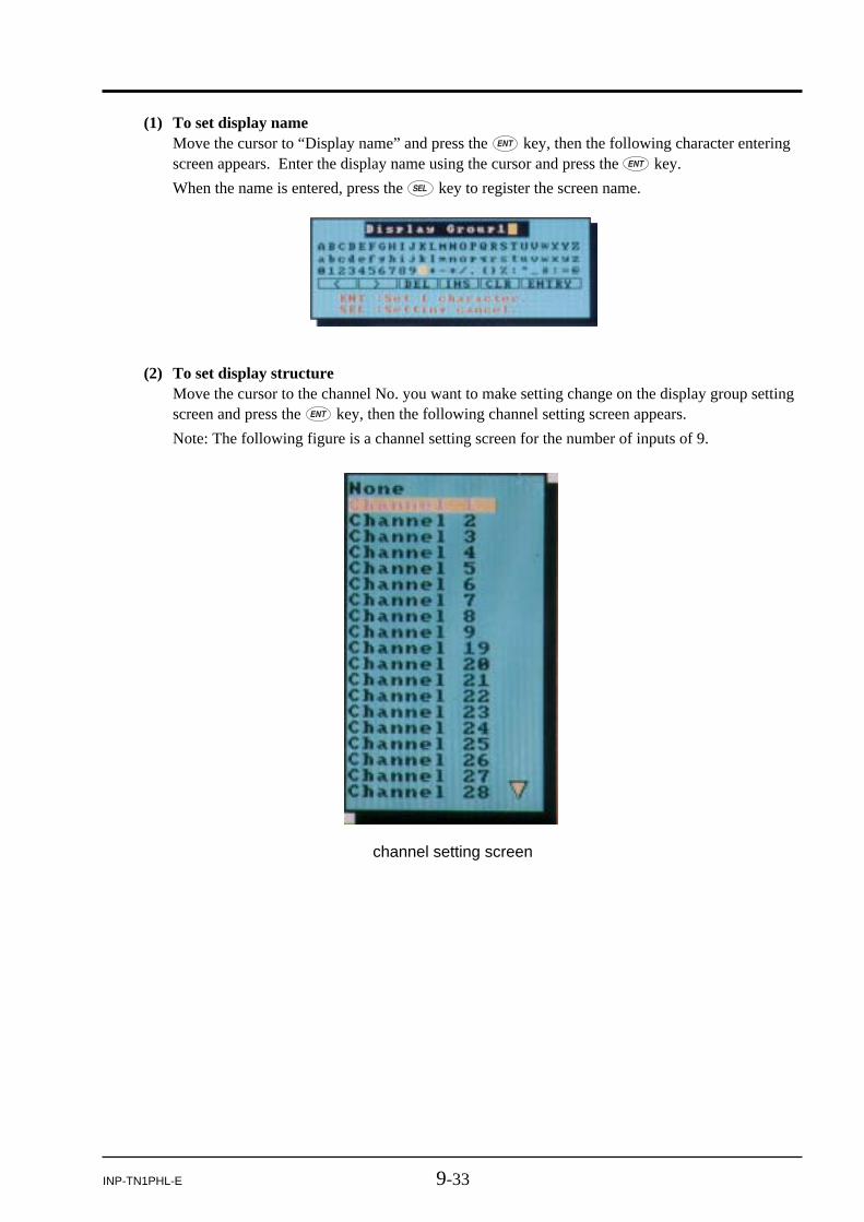
9-33INP-TN1PHL-E
(1) To set display nameMove the cursor to “Display name” and press the key, then the following character enteringscreen appears. Enter the display name using the cursor and press the key.
When the name is entered, press the key to register the screen name.
(2) To set display structureMove the cursor to the channel No. you want to make setting change on the display group settingscreen and press the key, then the following channel setting screen appears.
Note: The following figure is a channel setting screen for the number of inputs of 9.
channel setting screen

9-34 INP-TN1PHL-E
(3) To set trend direction
Move the cursor to “Trend direction” and press the key, then the setting screen appears.Select trend display direction using the cursor key and press the key.
Select channel No. using the cursor and press the key.
Selecting “None” does not make recording at that position on the data display screen.
The following is the relation between the No. of the display structure and the data display screen.
No.1 No.2 No.3 No.4
No.6 No.7 No.8 No.9
No.5
No.10
(4) To set the number of display division
Move the cursor to “Display divided” and press the key, then the number of display divisionsetting screen (1 to 20) appears. Select the number of division using the cursor key and press the
key.
Note) Display division is not allowed if scale display has been selected.

9-35INP-TN1PHL-E
(5) To set trend screen scale display
Move the cursor to “Scale display” and select “OFF” or “ON” using the cursor key. Then pressthe key.
The scale of the displayed channel can be arbitrarily changed using the key.
Note: If the input type is changed in the state where a chart is remaining on the trend screen,proper display cannot be obtained.
(6) To set graph display
Move the cursor to “Analog meter” and press the key, then the setting screen appears. Selecta bar gragh display using the cursor key and press the key.
* The analog meter displays only the channels from No. 1 to No. 4 in the screen structure.
(7) To select channel index
Move the cursor to “Channel index” and press the key, then the setting screen appears.
Select one from “Channel No. display,” “Tag No. display” and “Unit display” using the cursorkey and press the key.
* Only seven characters are displayed as TAG No. on the color bar.
In case of 4 channel display
It is selectable to display the combination and the parameter, “Channel index”.
The combination on the real time trend screen and bargraph screen can be set as shown below.
Tag display
area
Channel No.
Tag 1
PV
Tag 1
Tag 2
PV
Tag 1
Unit
PV
Channel index CH No. disp. Tag No. disp. Unit disp.

9-36 INP-TN1PHL-E
9.7 Setting method of F value calculation (Setting commonto all channels)
[Explanation]
• Select the calculation constants to be used for F value calculation (Extinction value calculation ofbacteria by sterilization by heating) that are common to all channels.
F value calculation constants: Reference temperature, Z value, Decimal point position
• By selecting a reset temperature, the F value can be reset.
• F value calculation can be manually reset.
[Operation]
Select the “parameter setting” on the menu screen and enter the password if the configuration pass-word has been set, then select “F value calculation setting”.
After that, following “F value calculation setting” screen appears.
Select target temperatureSelect Z valueSelect decimal point poisitionSelect F value reset temperatureManual reset request
(1) To set target temperatureMove the cursor to “Target temperature” and press the key, then then the following targettemperature setting screen appears. Enter the target temperature using the cursor and press the
key.
(2) To set Z valueMove the cursor to “Z value” and press the key, then the following Z value setting screenappears. Enter Z value using the cursor and press the key.

9-37INP-TN1PHL-E
(3) To set decimal point positionMove the cursor to “Decimal point” and press the key, then the decimal point position settingscreen appears. Select the decimal point position of F value calculation result using the cursorkey and press the key.
(4) To set F value reset temperatureSet F value reset temperature. If PV is less than this temperature, PHL make F value to zero.Move the cursor to “Reset temperature” and press the key, then the following F value resettemperature screen appears.
Enter the reset temperature using the cursor key and press the key.
(5) Manual reset requestTo reset manually the F value, move the cursor to “Manual reset” and press the key.

9-38 INP-TN1PHL-E
9.8 Setting totalizing (Setting common to all channels)[Explanation]
It is the common setting for all totalize type.
Each settings are effective to totalize type as shown below table.
Setting of totalize base timeSetting of totalize cycleSetting of weekly base daySetting of monthly base daySetting of totalize start/stop timeSetting of external input
[Operation]
Select the “parameter setting” on the menu screen and enter the password if the configuration pass-word has been set, then select “Totalize setting”.
After that, following “Totalize setting” screen appears.
Settings Periodic Daily Weekly Monthly Annualy Daily(Time) Externaly
Totalize base time
Totalize cycle
Weekly base day
Monthly base day
Totalize start/stop time
External input
: effective : non-effective

9-39INP-TN1PHL-E
(1) To set totalize base timeSet the totalize base time, date, day, cycle and so on.In case of totalize type is “Dairy”, PHL records at the setting of “Totalize base time” every day.In case of totalize type is “Weekly”, PHL records at the setting of “Totalize base time” on“Weekly base day”.In case of totalize type is “Monthly”, PHL records at the setting of “Totalize base time” on“Monthly base day”.In case of totalize type is “Annual”, PHL records at the setting of “Totalize base time” on January1st.In case of totalize type is “Periodic”, PHL records every “Totalize cycle” based on “Totalize basetime”. See following example.
[Example]
< settings > Totalize base time 10:17
Totalize cycle 20min
<Working> Recording start time : At 09:22
First recording : At 09:37 ← 10:17 + 23:20
Second recording : At 09:57 ← 10:17 + 23:40
Third recording : At 10:17 ← 10:17 + 24:00 = 10:17
Fourth recording : At 10:37 ← 10:17 + 00:20
Therfore, recording timing is at:
[ Totalize base time + Totalize cycle]

9-40 INP-TN1PHL-E
(3) To set weekly base daySet the data recording date for totalize type, “Weekly”.The setting is selected from Sunday, Monday, Tuesday, Wednesday, Thursday, Friday or Satur-day.
Operated at all timesRecording statusDITime
(2) To set totalize cycleSet the totalizing cycle for totalize type, “Periodic”.The setting is selected from 10, 20, 30 minites, 1, 2, 3, 4, 6, 12 or 24 hours.
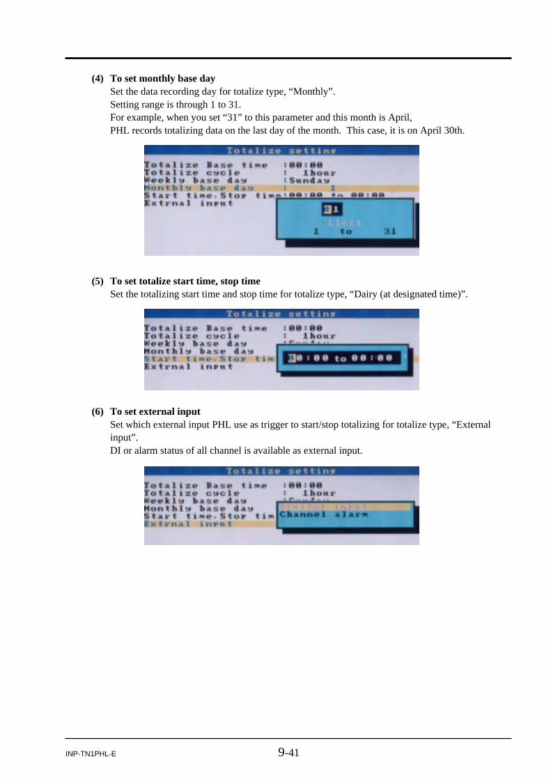
9-41INP-TN1PHL-E
(4) To set monthly base daySet the data recording day for totalize type, “Monthly”.Setting range is through 1 to 31.For example, when you set “31” to this parameter and this month is April,PHL records totalizing data on the last day of the month. This case, it is on April 30th.
(5) To set totalize start time, stop timeSet the totalizing start time and stop time for totalize type, “Dairy (at designated time)”.
(6) To set external inputSet which external input PHL use as trigger to start/stop totalizing for totalize type, “Externalinput”.DI or alarm status of all channel is available as external input.

9-42 INP-TN1PHL-E
9.9 Setting method of messages[Explanation]
• When various events occur, messages can be displayed.
• Up to 10 messages of 32 characters each can be registered.
• The message can be set with alphanumeric characters.
• Message timing to be displayed can be set at “ON/OFF of Alarm”, and ON/OFF of DI input.
• Message data can be recorded only in an event file of the memory card.
[Operation]
Select the "parameter setting" on the menu screen and enter the password if the configuration pass-word has been set, then select "Message setting" and desired message number.
After that, following message setting screen appears.
Message settingMessage display timing
(1) To set messagesMove the cursor to “Message” and press the key, then message screen appears as shownbelow. Enter message by the cursor and press the key for confirmation.
After entry of the message, press the key to return to message setting screen.

9-43INP-TN1PHL-E
(2) To set the message display timingMove the cursor to “Timing” and press the key, then message timing selection screen appearsas shown below. Select message timing by the cursor and press the key.
(3) To set the alarm No. and channel No. for the message.
Alarm number selecting screen
DI number selecting screen
Channel selecting screen

9-44 INP-TN1PHL-E
9.10 Unit definition[Explanation]
The Original unit definition screen allows you to make units with up to 7 alphanumeric characters. Upto 12 types of units can be registered. The unit can be verified by the unit selection given in Item 9.2.
[Operation]
Select the “parameter setting” on the menu screen and enter the password if the configuration pass-word has been set, then select “Original unit difinition”.
Then following “Original unit definition” screen appears.
Move the cursor to the unit box that remains blank by the cursor key. Press the key, and thefollowing unit naming screen appears.
Enter a unit by the cursor key and then press the key for confirmation.
After entry of the unit, press the key to return to the “original unie definition” screen.

9-45INP-TN1PHL-E
9.11 Setting method of DI (external control unit) function[Explanation]
Note: Up to 10 DIs are provided, which allows the following operations to be performed.
(1) Start/stop of record
Using DI, start/stop of the record can be switched.
• The record can also be started/stopped from the keypad on the front face.
• Start/stop switching function of the record is judged according to rise/fall edge of DI.
OFF → ON (Rise): Recording start (No change if the recording is made from the start.)
ON → OFF (Fall): Recording stop (No change if the recording is stopped from the start.)
(2) F value calculation reset
F value calculation can be reset using DI.
• F value calculation reset is judged based on Rise/Fall edge of DI.
OFF → ON (Rise): F value calculation is reset.
ON → OFF (Fall): No change
(3) Start/Stop of totalizing
Totalizing can be started/stopped using DI.
OFF → ON (Rise): Starts totalizing.
ON → OFF (Fall): Stops totalizing.
(4) Totalize reset
Totalize can be reset using DI.
• Totalize reset is judged based on Rise/Fall edge of DI.
OFF → ON (Rise): Totalizing data is reset.
ON → OFF (Fall): No change
(5) LCD ON
LCD can be turned on by DI.
It works as shown below.
(6) Message set
Message can be set using DI.
• In distinct from the function described in (1) to (5) above, message set can be set on the mes-sage setting screen.
• Message set function also works if the functions described in (1) to (5) shown above are allo-cated to DI. (Both the function allocated to DI and the message set function are operated.)
DI
Status OFF → ON ON → OFF
LCD off LCD turns on No change
LED ON No change No change

9-46 INP-TN1PHL-E
[Operation]
Select “Parameter setting” on the Menu screen and then “DI function setting” to display the DI func-tion setting screen.
DI function DI No.
Move the cursor to the DI No. with which DI function is to be selected and press the key.
By using the cursor key, select either one of “Function invalid,” “Record start/stop,” “F value calcula-tion reset,” “Totalize start/stop,” “Totalize reset” or “LCD ON”.

9-47INP-TN1PHL-E
9.12 Setting constant[Explanation]
Constants can be set to calculation function.
• The number of setting items can be set from 1 to 20.
[Operation]
Select the “parameter setting” on the menu screen and enter the password if the configuration pass-word has been set, then select “Constant setting”.
Then following “Constant setting” screen appears.
Move the cursor to a desired setting item, and press the key.
Enter the set value using the cursor key and press the key.
Set valueSelect item

9-48 INP-TN1PHL-E
9.13 Setting password for parameter setting[Explanation]
Four-digit password required to display the parameter setting screen and recording start and/or stopscreen can be set as follows.
Set “0000”, then password input isn’t required to display above screens.
[Operation]
Select the “parameter setting” on the menu screen and enter the password, then select “ConfigurationPassword set”.
Then following “Configuration Password set” screen appears.
Press the key, and password entry screen appears. Enter the password using the cursor key andpress the key.

10-1INP-TN1PHL-E
10.1 Displaying record data of memory card[Explanation]
The recorded data (trend data file) contained in the memory card set to the main unit can be displayedon the historical trend screen.
• The meaning of file name is as follows.
• S00****.FDT: File name of the trend data file (A00****.FDT, which is an event data file, isnot displayed.)
The part **** is substituted by 4-digit numerical value, and every time a newfile is created, the value increases sequentially beginning from 0000.
• Every time a recording is started using the key or by DI input, a new file is created.
A trend file and an event file are created as a set as a new file without fail.
• The date indicates the last time when the writing was conducted on the file.
• The file name cannot be changed on this screen. To change the file name, read in the data in amemory card on the PC. Observe the following when changing the file name.
1) Change both the trend data file (Sxx.FDT) and the event data file (Axx.FDT)
2) Be sure to give the trend data file a name beginning with S, and give the event data filea name beginning with A.
3) Be sure to give the same name to the part xxxx of Sxxxx.FDT and Axxxx.FDT. Other-wise the file may not be opened.
4) The file may not be opened with the names S.FDT and A.FDT.
5) Be sure to use 7 characters including S or A at the maximum. Otherwise the file maynot be opened.
6) Do not give the same file name to the part xxxx of Sxxxx.FDT and Axxxx.FDT in sepa-rate pairs.
Otherwise the program may not be properly operated and forced termination etc. mayoccur.
[Example]
Avoid giving the same file name, 88, to S88 in the upper stage and A88 in the lower stageas in the example shown below.
Before changeS01. FDT/A01.FDT 2002-11-19 10:00S02. FDT/A02.FDT 2002-11-19 15:38
After changeS88. FDT/A01.FDT 2002-11-19 10:00==S02. FDT/A88.FDT 2002-11-19 15:38==
10. OPERATING MEMORY CARD

10-2 INP-TN1PHL-E
[Operation]
Select the “CF manager and totalize exe”. on the menu screen and enter the password if the CFmanager password has been set, then select “Record data display”. Then following "Record datadisplay" screen appears.
(1) Select the file to be opened using the cursor key, and press the key to display the followingrecord data display screen.
(2) Select a screen group No. you want to display using the cursor key, and press the key.

10-3INP-TN1PHL-E
(3) Move the cursor to “Record data display” and press the key. Then move the cursor to “ON”and press the key.
The historical trend screen of the selected group No. is displayed.
Refer to Item 6.7 “Historical trend display” for the method of seeing the historical trend screen.
About loading data from the memory card, following settings are displayed according to currentlysettings not the saved settings
• Trend direction
• Number of screen division
• Trend scale display
• Color bar display selection
(4) Press the key while the historical trend screen is displayed, and following “Display timesetting” screen appears.
Enter the time of currently recorded data you want to display and press the key.Then, PHL displays historical trend data at entered day and time.To display past data, entered day and time appears the bottom of the historical screen. To displayfarther data, entered day and time appear the top of this screen.

10-4 INP-TN1PHL-E
10.2 Removing memory card (compact flash)[Explanation]
By prohibiting the writing to the memory card, the memory card can be removed without stopping therecording while recording or totalizing is in progress. Refer to [Operation] shown below for theremoving procedure.
• If the internal buffer (memory) of PHL becomes full while the memory card is being removed, therecord data is cut off.
• The internal buffer (memory) of PHL can store the data up to the following limit.
1) Trend data: 400 data (For 400 seconds when the display refresh cycle is 1 second)
2) Event data: 180 data
3) Totalizing data: 1 data (For 10 minutes when the totalizing record cycle is 10 minutes)
• When the memory card is reinserted after it is removed, a new record file (trend file, event file, or antotalizing file) is created.
[Operation]
Select the “CF manager and totalize exe.” on the menu screen and enter the password if the CFmanager password has been set, then select “Memory card abstract”. The following message appears.
(1) Clock display
Displays the date and the time.
(2) Memory card loading display
Displays the memory card loading status.
Flashing: Indicates the state where a memory card is not inserted.
Lit in green: Indicates the state where the memory card can be removed.
Lit in red: Indicates the state where the memory card cannot be removed.
(3) Memory card indicator
Displays the usage of the memory card in a bar graph. Lit in red when 90% of the whole capacityhas been used up.
(4) Memory card writing status display
Kept lit while the measured data is being written into the memory card.
qClock displaywMemory card
loading display eMemory card indicator
rMemory card writing status display

10-5INP-TN1PHL-E
Press the key. The following screen appears and the writing into the memory card is prohibited.Check that the memory card loading display is lit in green. Then then remove the memory card andback up the recorded data. After that insert the memory card once again and press the key. Theparameter display screen appears and the prohibition of writing into the memory card is released.

10-6 INP-TN1PHL-E
10.3 Totalizing start/stop setting[How to start totalize operation]
• Totalize operation can be started from the “Channel setting” or “Math channel setting” screen. Onthe “Totalize setting” screen shown above, set “Totalize calculation” to other than off, and performeither one of the following to start recording.
1) Set “Totalize start/stop” in “Menu/CF manager and Totalize exe.(/Password)/Totalize control” toON and press the [ENT] key twice.
2) Set “DI1 function” in “Menu/Parameter setting(/Password)/DI function setting” to “Totalizestart/stop” and set DI1 to ON (in the case of the recorder with DI).
[Explanation]
Totalize record file
• A file for totalize recording is created by totalize type as shown by the following table. (Recording ismade in the same format.)
Periodic cycle T000000.FDT
Daily report D000000.FDT
Weekly report W000000.FDT
Monthly report M000000.FDT
Annual report Y000000.FDT
Daily report (at designated time) R000000.FDT
External input E000000.FDT
• A totalize file is created in a totalize folder (folder name: T000000) in the recording folder.
• A totalize file is newly created every time the base totalize operation is turned on.
• While totalize operation is in progress, a new totalize file is not created even if the power is turnedoff.
• The reference time of recording of daily report, weekly report, monthly report, etc. cannot be se-lected individually but should be synchronized.
• If power failure occurs and power is restored later during totalize operation, the operation resumesstarting from the data before the power failure. (The data during the power failure is not totalized.)
• On totalize 4-channel display screen, totalize start/stop time and the previous totalized value aredisplayed.
• Totalizing data by the totalize recording cycle (and not the sum total during totalizing operation) isrecorded in the totalizing file.
• The data can be totalizing to 9 digits.
• If an input error (such as Over, Under, Burnout, Error) occurs, 0 is totalizing. (the error input is nottotalizing. However, if the input type is 0-5V input, and the input is kept open, the value equivalentto 0.26V is totalizing. If the input type is 0-500mV and the input is kept open, the value equivalentto 260mV is totalizing.)
• Displayed totalizing data is reset when the totalizing is started.

10-7INP-TN1PHL-E
[Operation]
Select Menu/CF manager and Totalize exe.(/Password)/Totalize control, and press key. Thentotalize control screen appears.
(1) To set totalize start/stop
Select “ON” or “OFF” at the parameter, “Totalize start/stop”.
• If “Totalize start/stop” is set to “ON,” totalizing is started when an totalizing start signal isreceived.
• If “Totalize start/stop” is set to “ON,” some parameter cannot be set. Refer to Appendix 3.
(2) Totalize reset request
Select this parameter and press the [ENT] key, then all the current totalize values are reset to zero.

10-8 INP-TN1PHL-E
10.4 Setting password for memory card operation[Explanation]
Four-digit password is required to display the “CF manager and Totalize exe.” screen can be set asfollows.
The default setting is “0000.”
[Operation]
Select the “CF manager and totalize exe.” on the menu screen and enter the password if the CFmanager password has been set, then select “CF manager password set”. The following “CF managerPassword set” screen appears.
Press the key, and the following password entry screen appears.
Enter the password and press the key.

11-1INP-TN1PHL-E
11. MAINTENANCE AND INSPECTION
11.1 Recommended replacement cycle of parts
11.2 CalibrationTo assure measuring accuracy, perform calibration every year.
For calibration procedure, refer to Chapter 12. Contact our sales representative for details.
11.3 Formatting the memory cardThe memory card should be formatted by a personal computer (this recorder is not provided with ameans of formatting the memory card).
Select a PC drive for the memory card and press the right-mouse button. The menu appears, prompt-ing you to select the option. Select “Format” as FAT16 or FAT. On the screen that appears, select the“Start” button to initiate the formatting.
Using CF card adaptor, please check how many capacities it can deal with. If your CF card is out ofthe range, don’t format CF card using the adaptor. When format CF card by the adaptor, you may findit complete format on the Windows. But in that case, PHL might not read the card.
Names of parts
LCD (front panel)LCD backlight cannot be replaced as a single unit. Return to factoryfor repair.
Cycle Remarks
5 years
5 years
When external fuses are used, replace them every 2 years for preventive maintenance.Fuse rating: 250V AC, 1A
2 years
• To prevent data from being lost, back up the recorded data once every 6 months.
• If writing error occurs in the memory card, data may be lost. If data has been written in the memory card to some extent, check if data writing has been normally performed.
6 months
Lithium battery It cannot be replaced as a single unit. Return to factory for repair.5 years
Panel packing
Fuse (external use)
Memory card

12-1INP-TN1PHL-E
12. CALIBRATION
The following operation can be carried out.
(1) Calibration of the measured value
(2) Initialization of the set value
12.1 Calibration method of measured values[Preparation]
Before calibration, prepare equipment as shown below:
Do not perform “Other functions” and “Adjust data initialization”, since theyare intended to be performed by the manufacturer. Otherwise the instrumentmay not operate properly causing phenomena that the input reading is notproperly displayed or the set parameter returns to the value set at the time ofdelivery.
CAUTION
[Explanation]
Adjustment is not required in an ordinary status. However, to maintain the desired accuracy of themeasured value display, we recommend you to perform calibration periodically by adding calibrationinput signals. Add calibration input signals to the channel to be calibrated. To calibrate the input of theresistance bulb, be sure to perform 500mV calibration beforehand, and then perform the calibration.
Note) If improper calibration input signals are added, the instrument operates improperly. Besure to follow the procedure shown above to perform calibration. Otherwise the instru-ment may operate improperly.
[Operation]
(1) Select the “Calibration password” on the menu screen and enter the password, “1234”, thenfollowing “Calibration” screen appears.
Equipment Specification
Power supply 0 to 300Vac / 5A
Voltage Generator 0 to 50VdcResolution: 10 µV (mV range)
Output impedance: less than 2 ohm
Resistance decade box Range: 0.01 to 400.000 ohmResolution: 0.01 ohm
Digital voltage meter Display: more than 5 and 1/2 digitsResolution: 1 µV (mV range)

12-2 INP-TN1PHL-E
(3) Select the channel for calibration.
Select the channel for calibration by using the cursor key and press the key.
(4) Apply 0% input
In the case of resistance bulb input, before performing calibration, be sure that 500mV inputcalibration has already finished.
The following are input signals for 0% point calibration.
• Voltage input: 0 mV or 0 V
• Thermocouple input: 0 mV
• Resistance bulb: 50ΩAfter input of the input signal for 0% calibration, wait for 30 seconds. Then press the key.Zero calibration will start automatically. After calibration, the “Setting completed” messageappears. Pressing moves to the next span calibration.
(5) Apply 100% input
The input signal for 100% calibration is shown below;
• Voltage input: 50 mV or 500 mV, and 5V
• Thermocouple input: 50 mV
• Resistance bulb: 300ΩAfter input of 100% calibration input signal, wait for 30 seconds. Then press the key. Spancalibration will start automatically. After calibration, the “Setting completed” message appears.Press the key.
(6) End of calibration
Move the cursor to “Adjustment completed” and press the key.
(2) Move the cursor to “Input adjustment.” and press the key, then the “input adjustment” screenappears.
Select channel No.
In case of 0 to 5V input type

12-3INP-TN1PHL-E
12.2 Initializing the measured value[Explanation]
Parameters can be returned to the value set at the time of delivery from the factory.
• After initializing the set value, be sure to store the initialized parameters in a nonvolatile memory.Otherwise they return to the values before the initialization when the power is turned off.
Note) Thought this function is executed, the adjusted values are not initialized.
[Operation]
(1) Select the “Calibration password” on the menu screen and enter the password, then “Calibration”screen appears. After that, select “Parameter initialization”, then following “Parameterinitialization”screen appears.
(2) Press the key to start initialization. To cancel it, press the key.

12-4 INP-TN1PHL-E
(3) Press the key, and the setting value of parameters are initialized at the shipment.

13-1INP-TN1PHL-E
13. TROUBLESHOOTING
Situation
Does not work at all.
Keys do not work.
“System Error” is displayed when power is ON.
The record swings over tothe 0% side or the 100%side.
The indication changestoo much.
The data indicatorindicates “Over”, “Under” or “Error”.
Recording data is not written in memory card
1) Is the power supply terminal connection correct?
Check Remedy
2) Is power being supplied properly?
Connect correctly.
Supply correctly.
1) Does the screen display correctly?If keys only do not work, key switch may be faulty.
2) There are some parameters that cannot be set duringrecording.Check if setting has been attempted during recording.
It is displayed when a fault occurs in CPU. Turn the powerON again. If it does not return to normal condition, CPU maybe faulty.
Contact our Service Center
Contact our Service Center.
Stop recording at once.
1) Is digital indication displayed correctly? If the input is notconnected correctly, burnout may occur or over- or under-indication may occur
2) The record swings over the indication range if theindication range is not set correctly.
Connect correctly.
Set the indication rangecorrectly.
Fix the memory cardaccording to Item 2.2.
• Connect correctly.• Set the input type
according to the input signal.
1) Is the memory card connected properly?
2) Is the memory card full?
“Recording has been stopped because the compact flash has run out of capacity. Replace the compact flash.” is kept displayed.
1) The compact flash has run out of capacity.
2) Was the key pressed after the compact flash is replaced with the one with sufficient capacity?
1) Replace the compact flash with the one with sufficient capacity, and then press the key.
2) Press the key.
“No battery! Please exchange the battery” is kept displayed.
Battery becomes low voltage. So, it might reset the clock at power on or it couldn’t work totalizing correctly.
Contact our ServiceCenter.
To match the indication to that of the field indicator, use PVshift given in Item 9.2 (12).
If the input is not connected correctly or a signal that isdifferent from the input type is connected, the indicationbecomes faulty.
3) If the measuring channel is set as “Indication only” or “Skip”, data is not recorded.
If the recorder does not operate normally, take a remedy according to the table given below. For a compli-cated trouble, contact our Sales Representatives.

14-1INP-TN1PHL-E
14. SPECIFICATIONS
1. Input
• Number of input points : 9 points or 18 points (Can be selected at the time of purchase)
• Input circuit : Input mutual isolationResistance bulb measured current: about 1 mA
• Measuring cycles : 9 or 18 points….100ms cycles
• Input types : Thermocouple, resistance bulb, DC voltage, and DC current (Shuntresistors are fitted in input terminals).
Note: Provide a shunt resistor (type PHZP0101) separately.
• Measuring rangeInput types Measuring range
Thermocouple BRSKEJTNWLUPN
400.0 to 1760.0°C0.0 to 1760.0°C0.0 to 1760.0°C–200.0 to 1370.0°C–200.0 to 800.0°C–200.0 to 1100.0°C–200.0 to 400.0°C0.0 to 1300.0°C0.0 to 1760.0°C–200.0 to 900.0°C–200.0 to 400.0°C0.0 to 1300.0°C
Resistance bulb JPt100Pt100Ni100Pt50Cu50
–200.0 to 600.0°C–200.0 to 600.0°C–60.0 to 180.0°C–200.0 to 600.0°C–50.0 to 200.0°C
DC voltage 50mV500mV1-5V0-5V
0.00 to 50.00mV0.0 to 500.0mV1.000 to 5.000V0.000 to 5.000V
Note) B, R, S, K, E, J, T, N : JIS C 1602, DIN IEC 584-1W : 5%Re-26%Re · W (Hoskins Mfg. Co. USA)L : Fe-Cu · Ni (DIN 43710)U : Cu-Cu · Ni (DIN 43710)PN: PlatinumJPt100 : JIS C 1604-1989 (Old JIS Pt 100)Pt100 : JIS 1604, DIN IEC 751
• Selection of input types : By key operation on the front panel.Note that the same input type (thermocouple, resistance bulb, voltage)should be set per 2 channels. Refer to “Setting method of inputtypes” for details.
• Burn-out function : Equipped in thermocouples and resistance bulb inputs as standard,and overswings the recording to 100% side.Thermocouple burn-out current: about 0.2 µA
• Input filter function : Settable for each channel (primary delay filter)Time constants are settable in the range from 0 to 900 sec.
• Scaling function : Possible by DC voltage (current) inputScaling range: -32767 to 32767Decimal position: settable at any pointUnit symbol: settable up to 7 digits and 12 types

14-2 INP-TN1PHL-E
• Subtraction function : Subtraction between each channel is allowed.
• Totalizing function : The measured value of each channel can be totalizing.The reference time can be selected from Day, Hour, Minute, andSecond.
• F value calculation function : F value (extinction value of bacteria by sterilization by heating) canbe calculated from the measured temperature by each channel.
• Square rooter function : Square rooter can be performed against the input value per eachchannel.
2. Indication
• Indicator : 5.7” TFT color LCD (320 x 240 dots) with backlight, no contrastadjustment
• Color of indication : 14 colors
• Applicable language : English
• Life of backlight : 50,000 hours (the complete indicator unit should be replaced whenreplacing backlight).
• Trend display : Direction: vertical and horizontalNumber of channels: 10 channels for the group on one screen (Input:18 points at the maximum)Display refreshment cycles: select from 1 sec to 12 hours.No numerical value display, Scale display/no-display can be selected.
• Bar graph display : Number of channels: 10 channels for the group on one screen (Input:18 points at the maximum)Display refreshment cycles: 1 sec
• Analog meter display : Display for up to 4 inputs per group (input from 1 to 4). Display inbar graphs or in analog meters can be selected.Display refresh cycle: 1 second
• Digital display : Number of channels: 10 channels for the group on one screen (Input:18 points at the maximum)Display refreshment cycles: 1 sec
• Totalizing data display : Number of channels: 10 channels for the group on one screen (Input:18 points at the maximum)Display refresh cycle: 1 second
• Event summary display : Alarm summary and message summary can be displayed.The message occurrence information and message display can beswitched.
• Parameter display/set : Already-set Data Display and Set Change Display screen
• TAG indication : No. of characters to be displayed: Up to 8 charactersCharacters to be displayed: Alphanumerical characters
• Historical trend display : The past data can be reproduced and displayed from the compactflash. The past data file can be read and displayed. With scrolldisplay function, Scale display/no-display can be selected.
• Number of screen groups : Four groups (Up to 10 channels per 1 group can be registered.)

14-3INP-TN1PHL-E
3. Keyboard
• No. of Keys : 8
• Function : Use to select various screens and set various parameters.
4. Recording function
• External memory media : Compact Flash card
• Recording capacity : A max. of 256 MB (Compact Flash card)
• Recording method : Turning ON the REC key allows measured data to be written at fixedcycles.Recorded as a new file whenever the recording starts
• Data save cycles : Linked to the display refreshment cycles on the “Real Time Trend”screen. However, they are automatically set to about 1 minute if therefreshment cycles are set to less than 1 minute.
• Trend data : Min. and max. measured values out of measured data that aresampled at the measuring cycles are saved.
• Event data : Saves alarm data and message data.
• Totalizing value data : Totalizing value data at designated timing is recorded per channel.
• Storage capacity : Approximately 1.5 years when the display refresh cycle is 30 seconds(in the case of 9-channel recording in ASCII data format, and 256MBcompact flash is used). Refer to Item 2.3.
• Residual capacity of memory: Indicates how much of the memory card has been used on the screen.If the residual capacity is short, the recording stops.
• Recommended card : Sandisk CorporationURL: http://www.sandisk.co.jpType: SDCFB-256-801Available at any PC shops
• Data format : Either of ASCII or binary format can be selected. (Switching cannotbe made while the recording is in progress. In the case of ASCIIformat, the data can be directly read on Excel, etc.)
Note: The data recorded in binary format cannot be read directly.
Approximately 166 bytes per 1 sampling (for 9-channel input inASCII format) or approximately 45 bytes (for 9-channel input inbinary format)
5. Alarm function
• No. of settings : Up to 4 alarms for each channel are settable.
• Type of alarm : High/Low limits
• Indication : Status (alarm types) is displayed on digital display unit when analarm occurs.History display on alarm summary (Alarm ON/OFF time and alarmtypes)
• Hysteresis : Set within the recording range of 0 to 100%.
• Relay output : Number of points; 10 (Option: Cannot be selected if the number ofinput points is 18.)

14-4 INP-TN1PHL-E
• Transistor output (Open collector):Number of points; 18 (option)
• Alarm latch function : holds alarm indication and alarm output after alarm reset.ON/OFF operation is performed according to key setting.
6. Power supply
• Rated power voltage : 100V to 240V AC
• Range of operating voltage : 90 to 264V AC
• Supply frequency : 50/60Hz (both employable)
• Power voltage
Power voltage
100V AC
240V AC
No option
About 32VA
About 42VA
7. Structure
• Mounting method : Panel-mounted (vertical panel) or portable (desktop type)
• Mounting posture : Rearward tilt within 0 to 30° horizontal 0°• Thickness of panel : 2 to 26 mm
• Materials : PC-ABS for case and bezel
• Color : Black
• External dimensions : Panel-mounted: 160 (W) × 144 (H) × 185 (D) mmPortable: 160 (W) × 179 (H) × 206.6 (D) mm
• Mass : About 1.5 kg (no option)
• External terminal board : Screw terminals (M3 thread)
8. Normal operating condition
• Power voltage : 90 to 264V AC
• Supply frequency : 50/60 Hz ±2% (both employable)
• Ambient temperature : Panel-mounted: 0 to 50°CPortable: 0 to 40°C
• Ambient humidity : 20 to 80% RH
• Vibration : 10 to 60Hz 0.2m/s2 or less
• Shock : None
• Magnetic field : 400 A/m or less
• Signal source resistance : Thermocouple input …. 1kΩ or lessResistance bulb input… 10Ω/wire or less (resistance of each wire of
3-wire system should be balanced).Voltage input… 0.1% or less of input resistance
• Mounting posture : Forward tilt 0°, backward tilt within 30°, horizontal 0°• Warm-up time : One hour or more after power ON

14-5INP-TN1PHL-E
9. Reference performance
• Accuracy/resolution : Measuring conditions (23±2°C, 65±10% RH, power voltage, fre-quency fluctuation within ±1%, no external noise, warm-up time of 1hour or more, vertical mounting, standard values of signal sourceresistance and wiring resistance… within 1%)
Input typesDigital indication
accuracyNote 1 Digital indication
resolution
Thermocouple BRSKEJTNWLUPN
± (0.15%+1 digit)
±(0.3%+1 digit) for the range shown below.
Thermocouple B : 400 to 600°C
Thermocouples R and S : 0 to 300°C
Thermocouples K, E, J, T, L, and U : -200 to -100°C
Resistancebulb
JPt100Pt100Pt50
± (0.15%+1 digit)
DC voltage 50mV500mV1-5V0-5V
± (0.15%+1 digit)
0.1°C
10µV100µV1mV1mV
Note 1) Digital indication accuracy is a percentage (%) of the value in themeasuring range.
Note 2) No error of reference contact compensation of thermocouple isincluded.
Ni100Cu50
± (0.5%+1 digit)
0.1°C
• Error of reference contact compensation:K, E, J, T, N, L, U, PN: ±0.5°CR, S, B, W: ±1.0°C(when measured at 0°C or more)
• Max. input voltage : Thermocouple, resistance bulb, DC voltage: ±10V DC (continuous)
• Input resistance : Thermocouple, DC voltage: About 1MΩ
10. Others
• Clock : With calendar function (Christian era)Accuracy: ±50 ppm or less (monthly error: about 2 minutes)However, time error of power ON/OFF is not included.
• Memory backup : Parameters are saved to the internal non-volatile flash memory.The clock is backed up with built-in lithium battery.Trend data is not backed up.
• Insulation resistance : 100 MΩ (when measured between each terminal and ground by usinga 500V DC megger)

14-6 INP-TN1PHL-E
• Withstand voltage : Power terminal – ground: 2000V AC, 1 minInput terminal – ground: 500V AC, 1 minAlarm terminal – ground: 2000V AC, 1 minAlarm terminal – alarm terminal: 750V AC, 1 minCommunication terminal – ground: 500V AC, 1 minAlarm terminal (open collector) – ground : 500V AC, 1 min
11. Effect on operation conditions
• Effect of power supply fluctuation:For the fluctuation in the range from 90 to 264VAC (Frequency:50/60Hz)Reading change: ±(0.2%+1 digit) or lowerFor the fluctuation in the range from 47 to 63Hz (Power voltage:100VAC)Reading change: ±(0.2%+1 digit) or lower
• Effect of input signal resistance:Thermocouple input: 30µV±1 digit per 100ΩDC voltage: Fluctuation for the resistance value equivalent to 0.1% ofthe input resistance: ±(0.2%+1 digit) or lowerResistance bulb (For wiring resistance of 10Ω for 1 line (the same for3 lines)Reading change: ±(0.2%+1 digit) or lower
• Effect of ambient temperature: Reading change: ±(0.3%+1 digit)/10°C or lower
• Effect of mounting position : For the backward 30° slantReading change: ±(0.2%+1 digit) or lower
• Effect of vibration : When sine wave of 10 to 60Hz with the acceleration of 0.2m/s2 isapplied in each direction for 2 hoursReading change: ±(0.2%+1 digit) or lower
12. Safety/EMC standard
• Safety standard : Based on IEC61010-1
• EMC standard : Based on EN61326
Note) In case of the 5th digit of model code is “2”, PHL isn’t based onabove standard.
13. Transportation/storage conditions
• Temperature : -10 to 60°C
• Humidity : 5 to 90%RH
• Vibration : 10 to 60Hz, 2.45m/s2 or lower
• Impact : 294m/s2 or lower (packed state)

14-7INP-TN1PHL-E
14. Additional function (Option)
Alarm relay output/DI (11th digit of code symbol: “1”)
The card with 10-point relay output and 5-point DI input can be mounted.
Cannot be mounted if the number of input points is 18.
• Terminal structure : M3 screw terminal
• Alarm relay output : 1a contact output (10 points), Individual channel or common output(OR output) allowed.
DO1 : Contact capacity;150V/3A AC, 30V/3A DC (resistance load)
DO2 to 10 : Contact capacity; 240V/3A AC, 30V/3A DC (resistance load)
• DI input : No voltage contact input (5 points)The following control is allowed by contact input.q Recording start/stopw Message sete F value calculation resetr Totalizing start/stopt Totalizing resety LCD turns ON
15. Support software
The following software is provided as standard.
Loader software for PC
• Major function : Performs various parameter setting/change of the main unit.
• O/S : Windows 98/2000/XP
• Required memory : 64MB or larger
• Disk drive : Windows 98/2000/XP-capable CD-ROM
• Hard disk capacity : Free capacity of 30MB or larger required
• Printer : Windows 98/2000/XP-capable printer and printer driver
Note: PC loader communication cable (type PHZP0201) is separately required.
Data viewer software
• Major function : Regenerates the past trend record on the PC from the data in thecompact flash. Provided with historical trend display and eventdisplay functions.
• O/S : Windows 98/2000/XP
• Required memory : 64MB or larger
• Disk drive : Windows 98/2000/XP-capable CD-ROM drive
• Hard disk drive : Free capacity of 30MB or larger required
• Printer : Windows 98/2000/XP-capable printer and printer driver
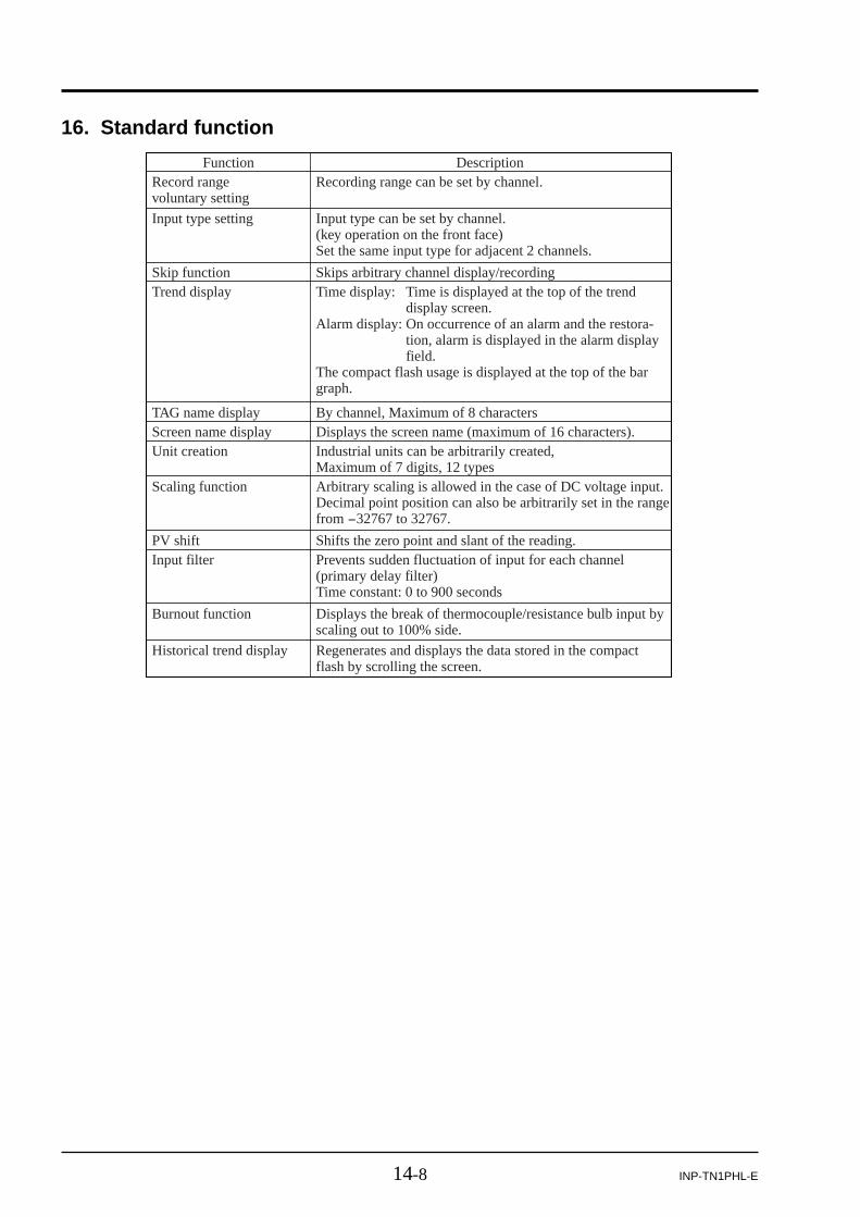
14-8 INP-TN1PHL-E
16. Standard function
FunctionRecord range voluntary setting
Input type setting
Skip functionTrend display
TAG name displayScreen name displayUnit creation
Scaling function
PV shiftInput filter
Burnout function
Historical trend display
DescriptionRecording range can be set by channel.
Input type can be set by channel. (key operation on the front face)Set the same input type for adjacent 2 channels.
Skips arbitrary channel display/recordingTime display: Time is displayed at the top of the trend
display screen.Alarm display: On occurrence of an alarm and the restora-
tion, alarm is displayed in the alarm display field.
The compact flash usage is displayed at the top of the bar graph.
By channel, Maximum of 8 charactersDisplays the screen name (maximum of 16 characters).Industrial units can be arbitrarily created, Maximum of 7 digits, 12 typesArbitrary scaling is allowed in the case of DC voltage input. Decimal point position can also be arbitrarily set in the range from -32767 to 32767.
Shifts the zero point and slant of the reading.Prevents sudden fluctuation of input for each channel (primary delay filter)Time constant: 0 to 900 seconds
Displays the break of thermocouple/resistance bulb input by scaling out to 100% side.
Regenerates and displays the data stored in the compact flash by scrolling the screen.

A-1INP-TN1PHL-E
APPENDICES
Appendix 1 Recording format (ASCII)
(1) Trend data file
MA
X. v
alue
and
MIN
. val
ue o
fea
ch c
hann
el
Par
amet
er s
et v
alue
s, c
hann
el N
o.,
TAG
nam
e, r
ecor
ded
colo
r, in
put t
ypes
,un
its, d
ispl
ay r
ange
(0%
), d
ispl
ayra
nge
(100
%),
etc
.
Not
e)D
ata
such
as
burn
-out
, err
or, a
nd ti
me
of o
ccur
renc
e ar
e re
cord
ed a
s –3
2768
(w
ith d
ecim
al p
oint
). O
ver-
/und
er r
ange
Indi
catio
n is
rec
orde
d as
327
67/ -
3276
7 (w
ith d
ecim
al p
oint
).

A-2 INP-TN1PHL-E
Message data
“Occurrence of alarm” dataYear, month, day, time, type (A), channel No., alarm No.Alarm types (1: H, 2: L)Alarm ON (1) and alarm OFF (0)
A000001.FDTPHL11B11-E10YYSNo.A2M0262T Ver.V07L 2002/ 4/18 23:32:00,A,01,2,02,12002/ 4/18 23:32:00,M,Low temperature attention ,012002/ 4/18 23:45:22,A,03,3,01,12002/ 4/18 23:45:22,M,Humidity is abnormal. ,012002/ 4/18 23:47:21,A,03,3,01,02002/ 4/18 23:47:28,A,03,4,02,12002/ 4/18 23:47:28,M,Humidity is abnormal. ,012002/ 4/19 00:39:46,A,03,4,02,02002/ 4/19 00:41:26,A,01,2,02,02002/ 4/19 00:41:26,M,Low temperature attention off ,012002/ 4/19 00:42:27,A,03,4,02,12002/ 4/19 00:42:27,M,Humidity is abnormal. ,012002/ 4/19 00:43:12,A,03,4,02,02002/ 4/19 00:52:37,A,01,1,01,12002/ 4/19 00:52:37,M,High temperature attention ,012002/ 4/19 02:05:58,A,01,1,01,02002/ 4/19 02:05:58,M,High temperature attention off ,012002/ 4/19 02:42:38,A,01,2,02,12002/ 4/19 02:42:38,M,Low temperature attention ,012002/ 4/19 02:55:48,A,03,3,01,12002/ 4/19 02:55:48,M,Humidity is abnormal. ,012002/ 4/19 02:57:51,A,03,3,01,02002/ 4/19 02:57:57,A,03,4,02,12002/ 4/19 02:57:57,M,Humidity is abnormal. ,012002/ 4/19 03:50:02,A,03,4,02,02002/ 4/19 03:51:40,A,01,2,02,02002/ 4/19 03:51:40,M,Low temperature attention off ,012002/ 4/19 04:02:53,A,01,1,01,12002/ 4/19 04:02:53,M,High temperature attention ,012002/ 4/19 05:16:14,A,01,1,01,02002/ 4/19 05:16:14,M,High temperature attention off ,01
(2) Event data file
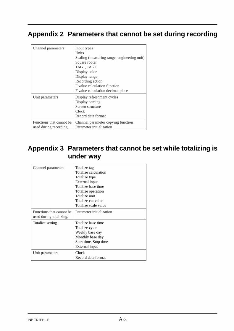
A-3INP-TN1PHL-E
Channel parameters Input typesUnitsScaling (measuring range, engineering unit)Square rooterTAG1, TAG2Display colorDisplay rangeRecording actionF value calculation functionF value calculation decimal place
Unit parameters Display refreshment cyclesDisplay namingScreen structureClockRecord data format
Functions that cannot be used during recording
Channel parameter copying functionParameter initialization
Appendix 2 Parameters that cannot be set during recording
Channel parameters Totalize tagTotalize calculationTotalize typeExternal inputTotalize base timeTotalize operationTotalize unitTotalize cut valueTotalize scale value
Functions that cannot be used during totalizing.
Parameter initialization
Totalize setting Totalize base timeTotalize cycleWeekly base dayMonthly base dayStart time, Stop timeExternal input
Unit parameters ClockRecord data format
Appendix 3 Parameters that cannot be set while totalizing isunder way

A-4 INP-TN1PHL-E
Appendix 4 Opening the PHL record data in ASCII format onExcel
Note 1: The record data in binary format cannot be opened following the procedure shown below.(Refer to Item 9.1 (11) for details.)
Note 2: The record data of 10MB or larger in case of 9-point input, and 5MB or larger in case of 18-point input cannot be opened on Excel. In these cases, read the data using the data viewer(contained in the attached CD-ROM) and perform CSV conversion to divide the file, whichallows the data to be read.
q Start up Excel, select “File(F)” and the “Open (O)” on the menu to display the following screen.
w Select “All” for the file type, and select PHL record data (S****.FDT).
e Selecting the file displays the following data format setting screen. Select “Dividing characterssuch as a comma or a tab…..” for the original data format, and then press the “Next” button.
r Pressing the “Next” button displays the following screen.
Check “Comma (C)” in the dividing character setting.
t Pressing the “Exit (E)” button displays the record data of PHL.
w
e

A-5INP-TN1PHL-E
Appendix 5 Timing of recordingThe timing of recording varies depending on display refresh cycle and integration record cycle.
Example: When the recording is started at 08:45 at the display refresh cycle of 20 minutes, the data is re-corded next when the clock indicates 0, that is, at 09:00. The recording will thus be performed at09:20, 09:40, 10:00 …..etc.
1 second
2 seconds
3 seconds
5 seconds
10 seconds
20 seconds
30 seconds
1 minute
2 minutes
3 minutes
5 minutes
10 minutes
20 minutes
30 minutes
1 hour
2 hours
3 hours
4 hours
6 hours
12 hours
Every second
Every even-numbered second
At 0, 3, 6, 9, 12, 15, 18, 21, 24, 27, 30, 33, 36, 39, 42, 45, 48, 51, 54, 57 seconds
At 0, 5, 10, 15, 20, 25, 30, 35, 40, 45, 50, 55 seconds
At 0, 10, 20, 30, 40, 50 seconds
At 0, 20, 40 seconds
At 0, 30 seconds
Every minute (When 0 is displayed. The same for the following)
Every even-numbered minute
At 0, 3, 6, 9, 12, 15, 18, 21, 24, 27, 30, 33, 36, 39, 42, 45, 48, 51, 54, 57 minutes
At 0, 5, 10, 15, 20, 25, 30, 35, 40, 45, 50, 55 minutes
At 0, 10, 20, 30, 40, 50 minutes
At 0, 20, 40 minutes
At 0, 30 minutes
Every hour (When “0 m :0 s” is displayed. The same for the following)
Every even-numbered hour
At 0, 3, 6, 9, 12, 15, 18, 21 hours
At 0, 4, 8, 12, 16, 20 hours
At 0, 6, 12, 18 hours
At 0, 12 hours
Display refresh cycle Data is recorded when the PHL clock indicates the following time.

Head office6-17, Sanbancho, Chiyoda-ku, Tokyo 102-0075, Japanhttp://www.fesys.co.jp
Sales Div.International Sales Dept.No.1, Fuji-machi, Hino-city, Tokyo 191-8502, JapanPhone: 81-42-585-6201, 6202 Fax: 81-42-585-6187http://www.fic-net.co.jp


