14
PAPI System Hella Induperm type 801 USER MANUAL GB

PAPI System Hella Induperm type 801
USER MANUAL
GB

PAPI 801 MANUAL-GB
Version Aa:25-06-2014 2 of 14 pages
LIST OF CONTENT
1. General information ............................................................................................. 3
1.1 The layout of this manual .................................................................................................... 3
1.2 The use of the manual .......................................................................................................... 3
1.3 Manufacturer information .................................................................................................... 3
1.4 Document information ......................................................................................................... 3
2. General overview of PAPI functions .................................................................. 4
3. Mode of Operation ............................................................................................... 5
4. Description of the PAPI unit ............................................................................... 6
5. Features ................................................................................................................. 7
6. Hella Induperm PAPI specification .................................................................... 7
7. Installation ........................................................................................................... 10
8. Adjustments ........................................................................................................ 11
9. Maintenance ........................................................................................................ 11
10. List of Spares ....................................................................................................... 12
10.1 Assembly drawing ............................................................................................................. 12
10.2 List of components ............................................................................................................. 13
11. Certificates .......................................................................................................... 14

PAPI 801 MANUAL-GB
Version Aa:25-06-2014 3 of 14 pages
1. General information 1.1 The layout of this manual This manual includes technical information about the Hella Induperm range of PAPI Light fixtures. All PAPI types are constructed and manufactured with the same mechanical and optical parts. However, the PAPI units can be supplied with one, two or three optical systems and with different height of light output center. 1.2 The use of the manual The manual is intended to be used for installation, operation, maintenance of the PAPI unit in a PAPI system with four or eight units or in an APAPI system with only two PAPI units. The manual is also nescessary for purchase of spare parts. 1.3 Manufacturer information The PAPI 801 are developed and manufactured by: HELLA INDUPERM A/S Københavnsvej 1 DK-4800 Nykøbing Falster DENMARK Tel.: +45 5486 0200 Fax.: +45 5486 0389 E-Mail: [email protected] Homepage: www.induperm.dk or www.hella.com/airportlighting 1.4 Document information
Version Date Author Approved A –First release 2014.4.25 Ole Lund-Hermansen OLH
Version Date Author Approved Comments
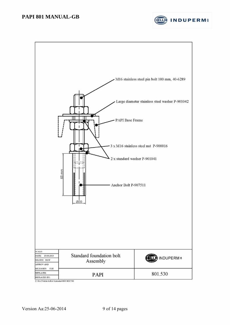
Aa 2014.6.25 OLH OLH Foundation bolt drwg. added
This manual includes a number of safety instructions, but national instructions as well as IEC 61820, Annex C, must be observed.
Hella Induperm A/S reserves the right to changes without notice.
It is not allowed to copy this manual without permission.

PAPI 801 MANUAL-GB
Version Aa:25-06-2014 4 of 14 pages
2. General overview of PAPI functions
The PAPI system is a simple and reliable visual aid which enables the pilot to establish and
maintain an exact glide path. The system secures the safe and accurate guidance for the pilot
throughout the final approach phase to touch-down, both day and night.
A standard PAPI system comprises a wing bar of 4 light units located alongside the runway on its
left, at the glide path origin and facing the approach. If further horizontal guidance is required, a
second wing bar on the opposite side of the runway can be established.
The optical system divides the light beam of the unit in an upper half showing white and a lower
half showing red. The transition at the centre of the vertical range is of so short a duration that the
light gives an eye-catching click within a range of less than 3 minutes of arc.
The four units forming a wing bar are set up at the glide path origin (TDZ point). The light unit next
to the runway edge (light unit D) is adjusted to an angle 30’ higher than the nominal glide path
angle. The next light unit (light unit C) is adjusted 20’ higher than D and so on. This is shown on
Fig. 1.
The TDZ point must be co-ordinated with the ILS system (if available), or the distance between
TDZ-point and Threshold can be calculated to secure a minimum Threshold clearance of 15m for
all relevant types of aircraft.
Hella Induperm PAPI can be supplied as 2-light units (2 x 200W Pk30d) or as 3-light units (3 x
200W Pk30d). As an option, the units can be supplied with heating elements on the lenses to
prevent ice and / or mist.

PAPI 801 MANUAL-GB
Version Aa:25-06-2014 5 of 14 pages
3. Mode of Operation
The optical system divides the light beam of the units in an upper half showing white and a lower
half showing red. The transition at the centre of the vertical range is of so short a duration that the
lights give an eye-catching click within a range of less than 3 minutes of arc.
Projector Colour filter Lens
The four units forming a wing bar are set up at the glide path origin so that any two adjacent units
subtend a light beam angle axis of 20’.
On approach, the pilot is presented with a red/white light pattern
that informs him instantly of his vertical position relative to the
designated glide path, enabling him to adjust the rate of descent to
acquire the correct glide slope or, if necessary, fly a low or high
approach in complete safety.
D
C
B
A
D
C
B
A
HIGH 330’
SLIGHTLY HIGH 310’
ON SLOPE 3
SLIGHTLY LOW 250’
LOW 230’
α
15m
9m
300-400m (TYPICAL) THRESHOLD

PAPI 801 MANUAL-GB
Version Aa:25-06-2014 6 of 14 pages
4. Description of the PAPI unit
The PAPI units can be seen on the drawings 801.813/1 (3 lamp unit) and 801.823/1 (2 lamp type.
The main parts in PAPI units are as follows:
Stainless steel housing
Stainless steel cover
3-legged bottom frame, with adjustable legs.
Lenses
Red filters with eccentrics for adjustments
Aluminium reflectors
Control plane for angel adjustment
The PAPI unit is constructed and adjusted to have centre of lamp, edge of red filter and centre of
lens on one line to secure the sharp transition.
In the factory the PAPI unit is adjusted to 0° in both light direction and perpendicular to the light
direction (measured on the control plane), and in this position is the following controlled / adjusted:
Light output is also 0°
Transition sector is completely identical for all (2 or 3) light systems in the PAPI unit
The transition sector is horizontal
The PAPI unit is now adjusted to a sharp transition between red and white, and the angel on the
control plane will be the same as the angel of the light output.
The angel of the light output can now be adjusted by adjusting the ball joint on the back leg.

PAPI 801 MANUAL-GB
Version Aa:25-06-2014 7 of 14 pages
5. Features Easy installed and adjusted
No tool needed for re-lamping, and no additional adjustments required
Non-corrosive cabinet of a reliable mechanical construction
Standard 200W-6,6A Pk30d lamps used
Standard base frame includes breakable couplings
6. Hella Induperm PAPI specification The PAPI units can be supplied with light plane height above ground between 350mm and
700mm. The standard value is 550mm. The height can typically be adjusted ± 20 mm.
Light output app. 35.000cd (white) / 10.000cd (red) for one 200W light system. To be
multiplied with 2, respectively 3 dependant on the number of lamps in the PAPI unit.
Lamps: 200W-6,6A- Pk30d-1000Hour
Weight app. 40 KG
Cover in aviation yellow, the rest is black.
Breakable coupling included
Foundation bolts are not included as standard. Standard 16mm hot dip galvanized bolts with
accessories can be used or we can offer a stainless foundation kit type 801.530
Cable entry for each lamp through PG 13,5 gland. Connection directly to male connector on
Pk30 bulb as standard.
Optional FAA cable can be supplied in length according to customer request
The PAPI light fixture can as an option be equipped with a heater system including a heater for
each lens and a thermostat. Total power is 75W with an input voltage of 48VAC. The heater kit
is to order as type 801.845.

PAPI 801 MANUAL-GB
Version Aa:25-06-2014 8 of 14 pages
Max. 1275 Min. 475
618mm651mm
PAPI 801 MANUAL-GB
Version Aa:25-06-2014 9 of 14 pages

PAPI 801 MANUAL-GB
Version Aa:25-06-2014 10 of 14 pages
7. Installation
If the runway has ILS, the TDZ point for the PAPI system must be the same as the theoretical TDZ
point for the ILS.
If not, the airport authorities can determine the TDZ point or the minimum distance from the
Threshold can be calculated as follows:
The minimum Threshold clearance is 15m.
1. Runway is horizontal:
Distance from Threshold = L (in m) =>
L = 15 / tan (α), where α = glide slope angel
2. TDZ is D (in m) lower than Threshold:
Distance from Threshold = L (in m) =>
L = (15+D) / tan (α), where α = glide slope angel
3. TDZ is D (in m) higher than Threshold:
Distance from Threshold = L (in m) =>
L = (15-D) / tan (α), where α = glide slope angel
Placed in the TDZ point, the PAPI units have to have their light output centre, the light plane, in
level with the centre of the runway. It means that the top of the foundation must be 550mm (for a
standard height of PAPI units) lower than the centre of the runway. If that’s not possible, either the
TDZ point or the PAPI units must be displaced.
Each PAPI unit is mounted on a stable concrete foundation by means of 3 anchor bolts. The light
output must be parallel to the runway or have a very small toe-in.
The PAPI units are mounted on the anchor bolts, and the bottom frame levelled.
By means of the ball joints on each leg, the PAPI unit is adjusted to the correct light output plane
with the housing app. Levelled.

PAPI 801 MANUAL-GB
Version Aa:25-06-2014 11 of 14 pages
8. Adjustments
The ball joints on the 3 legs are adjusted until the PAPI light unit has the correct light output level,
and at the same time the factory adjusted control plane in the PAPI unit is 0° in both light direction
and perpendicular to the light direction. This is measured by means of the high accuracy digital
clinometers, see the following figure.
Then the digital clinometer is placed on the control plane in the light direction, and the ball joint on
the back leg is adjusted to the desired angel for each individual PAPI light unit. Be careful not to
touch the housing during the adjustment as angel adjustment is very sensitive.
Please read the manual for the digital clinometers carefully before use to know how to handle this
very sensitive, high-tech device. Please note, that the battery must be changed regularly to maintain
the factory calibration of the digital clinometers.
9. Maintenance
Once a month the PAPI light fixtures should be maintained and controlled as follows:
1. The lenses are cleaned.
2. Reflectors and filters are carefully cleaned with a dry, soft cloth.

PAPI 801 MANUAL-GB
Version Aa:25-06-2014 12 of 14 pages
Make sure, that the filters are in the correct position in groove in the eccentrics
3. Control that the lamps are working, and that the filament in the lamps is in the correct position
(if the filament in the lamp starts “hanging” the transition sector for the actual light output will
have moved).
4. Use the digital clinometers to control the setting of each PAPI unit, both in the light direction
and perpendicular to the light direction.
5. Switch-on the PAPI light in the highest intensity step, and look at the light output from the
longest distance, where the transition from white to red can be seen. The transition must be
sharp and simultaneous for all light system in the PAPI unit.
a. If not, control the position of the filters or
b. Change the lamps (be careful to place the lamp correct)
10. List of Spares
10.1 Assembly drawing

PAPI 801 MANUAL-GB
Version Aa:25-06-2014 13 of 14 pages
10.2 List of components
* optional parts
* *

PAPI 801 MANUAL-GB
Version Aa:25-06-2014 14 of 14 pages
11. Certificates


