18
Doc. No. MH*-OMD0082-A PRODUCT NAME Parallel Type Air Gripper MODEL / Series / Product Number MHZ2-6□ MHZJ2-6□ MHZA2-6□ MHZAJ2-6□

Doc. No. MH*-OMD0082-A
PRODUCT NAME
Parallel Type Air Gripper
MODEL / Series / Product Number
MHZ2-6□ MHZJ2-6□ MHZA2-6□ MHZAJ2-6□

Contents
Safety Instructions
1. Product Specifications
1-1. Specifications
2. Operating method or operation
2-1. Design precautions
2-2. Selection
2-3. Mounting
2-4. Air supply
2-5. Piping
2-6. Operating environment
2-7. Lubrication
3. Maintenance
3-1. Precautions
3-2. Replacement of Dust Cover (MHZJ2 / MHZAJ2 Only)
3-3. Construction / Parts list, seal list・・・MHZ2-6□
3-4. Construction / Parts list, seal list・・・MHZJ2-6□
3-5. Construction / Parts list, seal list・・・MHZA2-6*□
3-6. Construction / Parts list, seal list・・・MHZAJ2-6□
-1-

Safety Instructions These safety instructions are intended to prevent hazardous situations and/or equipment damage. These instructions indicate the level of potential hazard with the labels of “Caution,” “Warning” or “Danger.” They are all important notes for safety and must be followed in addition to International Standards (ISO/IEC)*1) , and other safety regulations. *1) ISO 4414: Pneumatic fluid power -- General rules relating to systems. ISO 4413: Hydraulic fluid power -- General rules relating to systems. IEC 60204-1: Safety of machinery -- Electrical equipment of machines .(Part 1: General requirements) ISO 10218: Manipulating industrial robots -Safety. etc.
Caution Caution indicates a hazard with a low level of risk which, if not avoided, could result in minor or moderate injury.
Warning Warning indicates a hazard with a medium level of risk which, if not avoided, could result in death or serious injury.
Danger Danger indicates a hazard with a high level of risk which, if not avoided, will result in death or serious injury.
Warning 1. The compatibility of the product is the responsibility of the person who designs the equipment or
decides its specifications. Since the product specified here is used under various operating conditions, its compatibility with specific equipment must be decided by the person who designs the equipment or decides its specifications based on necessary analysis and test results. The expected performance and safety assurance of the equipment will be the responsibility of the person who has determined its compatibility with the product. This person should also continuously review all specifications of the product referring to its latest catalog information, with a view to giving due consideration to any possibility of equipment failure when configuring the equipment.
2. Only personnel with appropriate training should operate machinery and equipment. The product specified here may become unsafe if handled incorrectly. The assembly, operation and maintenance of machines or equipment including our products must be performed by an operator who is appropriately trained and experienced.
3. Do not service or attempt to remove product and machinery/equipment until safety is confirmed. 1.The inspection and maintenance of machinery/equipment should only be performed after measures to
prevent falling or runaway of the driven objects have been confirmed. 2.When the product is to be removed, confirm that the safety measures as mentioned above are implemented and the power from any appropriate source is cut, and read and understand the specific product precautions of all relevant products carefully. 3. Before machinery/equipment is restarted, take measures to prevent unexpected operation and malfunction.
4. Contact SMC beforehand and take special consideration of safety measures if the product is to be used in any of the following conditions. 1. Conditions and environments outside of the given specifications, or use outdoors or in a place exposed to direct sunlight. 2. Installation on equipment in conjunction with atomic energy, railways, air navigation, space, shipping,
vehicles, military, medical treatment, combustion and recreation, or equipment in contact with food and beverages, emergency stop circuits, clutch and brake circuits in press applications, safety equipment or other applications unsuitable for the standard specifications described in the product catalog.
3. An application which could have negative effects on people, property, or animals requiring special safety analysis.
4.Use in an interlock circuit, which requires the provision of double interlock for possible failure by using a mechanical protective function, and periodical checks to confirm proper operation.
-2-
Safety Instructions
Caution The product is provided for use in manufacturing industries.
The product herein described is basically provided for peaceful use in manufacturing industries. If considering using the product in other industries, consult SMC beforehand and exchange specifications or a contract if necessary.
If anything is unclear, contact your nearest sales branch.
Limited warranty and Disclaimer/Compliance Requirements The product used is subject to the following “Limited warranty and Disclaimer” and “Compliance Requirements”. Read and accept them before using the product.
Limited warranty and Disclaimer
1.The warranty period of the product is 1 year in service or 1.5 years after the product is
delivered,whichever is first.∗2) Also, the product may have specified durability, running distance or replacement parts. Please consult your nearest sales branch.
2. For any failure or damage reported within the warranty period which is clearly our responsibility, a replacement product or necessary parts will be provided. This limited warranty applies only to our product independently, and not to any other damage
incurred due to the failure of the product. 3. Prior to using SMC products, please read and understand the warranty terms and disclaimers
noted in the specified catalog for the particular products.
∗2) Vacuum pads are excluded from this 1 year warranty. A vacuum pad is a consumable part, so it is warranted for a year after it is delivered.
Also, even within the warranty period, the wear of a product due to the use of the vacuum pad or failure due to the deterioration of rubber material are not covered by the limited
warranty.
Compliance Requirements
1. The use of SMC products with production equipment for the manufacture of weapons of mass destruction(WMD) or any other weapon is strictly prohibited.
2. The exports of SMC products or technology from one country to another are governed by the relevant security laws and regulation of the countries involved in the transaction. Prior to the shipment of a SMC product to another country, assure that all local rules governing that export are known and followed.
Caution SMC products are not intended for use as instruments for legal metrology. Measurement instruments that SMC manufactures or sells have not been qualified by type approval tests relevant to the metrology (measurement) laws of each country.
Therefore, SMC products cannot be used for business or certification ordained by the metrology
(measurement) laws of each country.
-3-

- 4 -
1. Product Specifications
1-1. Specifications Specifications
Model No. MHZ2-6□ MHZJ2-6□ MHZA2-6□ MHAJ2-6□
Cylinder inside diameter (mm) 6
Fluid Air
Operating pressure (Mpa)
Double acting: D 0.15 to 0.7
Single acting
Normally open: S
0.3 to 0.7 Normally
closed: C
Ambient and fluid temperature (oC) -10 to 60
Repeatability (mm) +/-0.01
Maximum operating frequency (c.p.m.) 180
Lubrication Lubrication not required.
Action Double acting, single acting
Note 1) Gripping force per finger Effective value (N)
D
O.D. External gripping
force
3.3
I.D. Internal gripping
force
6.1
S O.D.
External gripping force
1.9
C I.D.
Internal gripping force
3.7
Open/close stroke (Both sides)(mm) 4
Note 2) Weight (g) 27 28 26 27
Note 1) Values based on pressure of 0.5 MPa, gripping point L=20 mm, at center of stroke. Note 2) Values excluding weight of auto switch.
- 5 -
2. Operating method or operation
2-1. Design precautions
! Warning 1. The product is designed for use only in compressed air systems. Do not operate at
pressures or temperatures, etc., beyond the range of specifications, as this can cause damage or malfunction. (Refer to the specifications.) Please contact SMC if using for fluids other than compressed air. We do not guarantee against any damage if the product is used outside of the specification.
2. Take safety measures (e.g. mounting protective covers) when workpieces pose a danger of fingers being caught in a gripper, etc.
3. There is a danger of workpieces dropping if there is a decrease in gripping force due to a drop in circuit pressure caused by a power failure, etc. It is necessary to take measures such as drop prevention so that injury and damage to machinery or euqipment can be prevented.
4. If the product is used for the purpose other than the transportation of a workpiece such as positioning or clamping, please consult SMC.
2-2. Selection
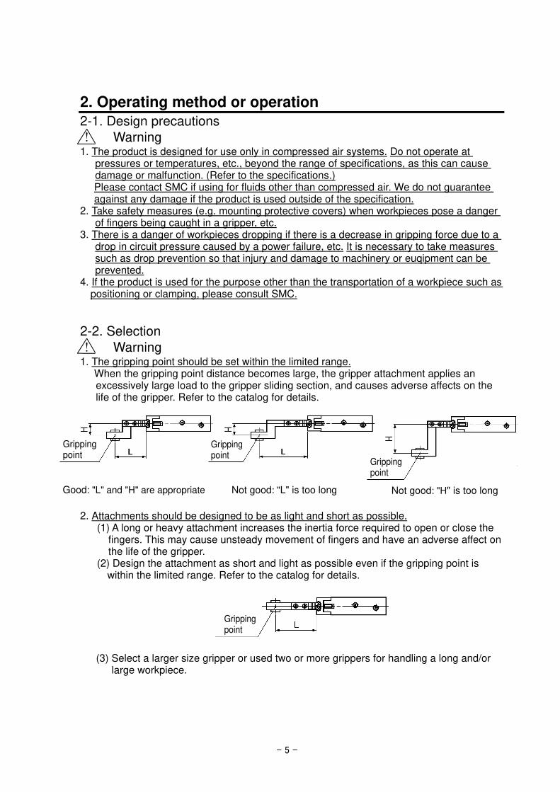
! Warning 1. The gripping point should be set within the limited range.
When the gripping point distance becomes large, the gripper attachment applies an excessively large load to the gripper sliding section, and causes adverse affects on the life of the gripper. Refer to the catalog for details.
2. Attachments should be designed to be as light and short as possible.
(1) A long or heavy attachment increases the inertia force required to open or close the fingers. This may cause unsteady movement of fingers and have an adverse affect on the life of the gripper.
(2) Design the attachment as short and light as possible even if the gripping point is within the limited range. Refer to the catalog for details.
(3) Select a larger size gripper or used two or more grippers for handling a long and/or large workpiece.
Good: "L" and "H" are appropriate Not good: "L" is too long Not good: "H" is too long
Gripping point
Gripping point
Gripping point
Gripping point
- 6 -
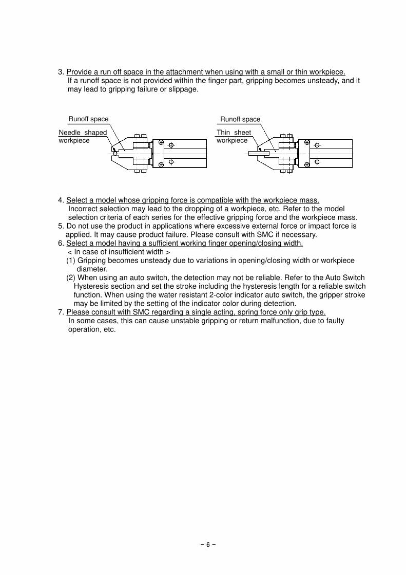
3. Provide a run off space in the attachment when using with a small or thin workpiece. If a runoff space is not provided within the finger part, gripping becomes unsteady, and it may lead to gripping failure or slippage.
4. Select a model whose gripping force is compatible with the workpiece mass. Incorrect selection may lead to the dropping of a workpiece, etc. Refer to the model selection criteria of each series for the effective gripping force and the workpiece mass.
5. Do not use the product in applications where excessive external force or impact force is applied. It may cause product failure. Please consult with SMC if necessary.
6. Select a model having a sufficient working finger opening/closing width. < In case of insufficient width > (1) Gripping becomes unsteady due to variations in opening/closing width or workpiece
diameter. (2) When using an auto switch, the detection may not be reliable. Refer to the Auto Switch
Hysteresis section and set the stroke including the hysteresis length for a reliable switch function. When using the water resistant 2-color indicator auto switch, the gripper stroke may be limited by the setting of the indicator color during detection.
7. Please consult with SMC regarding a single acting, spring force only grip type. In some cases, this can cause unstable gripping or return malfunction, due to faulty operation, etc.
Runoff space
Thin sheet workpiece
Runoff space
Needle shaped workpiece

- 7 -
2-3. Mounting
! Warning
1. Install and operate the product only after reading the Operation Manual carefully and understanding its contents. Also, keep the manual where it can be referred to as necessary.
2. Allow sufficient space for maintenance and inspection. 3. Do not drop or hit the product when mounting to avoid scratches and dents.
Even slight deformation can cause the deterioration of accuracy and operation failure. 4. Tighten the mounting screws of the attachment with the specified torque.
Tightening the screws with a higher torque than the maximum may cause malfunction. In addition, tightening the screws with a lower torque can cause the displacement of the mounting position or in extreme conditions, detaching of the work piece.
Mounting attachment to the finger
The attachment should be mounted with the torque specified in the following table by screwing the bolt into the female mounting thread of the finger.
5. Tighten the screw within the specified torque range when mounting the air gripper.
Tightening with a torque above the limit can cause malfunction, while insufficient tightening can cause slippage and dropping.
Model No Screw Max. tightening torque (N・m)
MHZ2-6□
MHZJ2-6□
MHZA2-6□
MHZAJ2-6□
M2x0.4 0.15
Attachment

- 8 -
Mounting Gripper
Axial mounting (Body tapped)
Vertical mounting (Body tapped)
Side mounting (Body tapped)
Horizontal mounting (Body tapped)
Model No. Screw Max. tightening
torque (N・m) Maximum screw-in
depth (mm)
MHZ2-6□
M3 x 0.5 0.88 10 MHZJ2-6□
MHZA2-6□
MHZAJ2-6□
Model No. Screw Max. tightening
torque (N・m)
MHZ2-6□
M2.5x0.45 0.49 MHZJ2-6□
MHZA2-6□
MHZAJ2-6□
Model No. Screw Max. tightening
torque (N・m) Maximum screw-in
depth (mm)
MHZA2-6□ M2x 0.4 0.15 4
MHZAJ2-6□
Note) Except MHZ2-6□ and MHZJ2-6□.
Use the holes on the body end surface for positioning.
Model No. Screw Max. tightening
torque (N・m)
Max. thread depth (mm)
Hole diameter
(mm)
Hole depth
(mm)
MHZA2-6□ M2×0.4 0.15 4.5 φ7H8(+0.022/0) 1.5
MHZAJ2-6□
Note) Axial mounting type is not available for MHZ2-6□ and MHZJ2-6□.
- 9 -
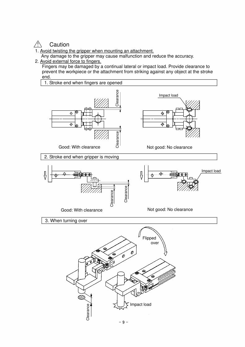
! Caution
1. Avoid twisting the gripper when mounting an attachment. Any damage to the gripper may cause malfunction and reduce the accuracy.
2. Avoid external force to fingers. Fingers may be damaged by a continual lateral or impact load. Provide clearance to prevent the workpiece or the attachment from striking against any object at the stroke end.
1. Stroke end when fingers are opened
2. Stroke end when gripper is moving
3. When turning over
Cle
ara
nce
Cle
ara
nce
Good: With clearance Not good: No clearance
Impact load
Good: With clearance Not good: No clearance
Cle
ara
nce
Cle
ara
nce
Impact load
Flipped over
Impact load
Cle
ara
nce

- 10 -
3. Adjust the gripping point so that an excessive force will not be applied to the fingers when inserting a workpiece. Confirm that the gripper can operate without receiving any shock by testing it in manual operation mode or by low speed operation.
4. Control the opening/closing speed with the speed controller to avoid excessive high
speed operation. If the finger opening/closing speed is greater than necessary, impact forces on the fingers and other parts will increase. This can cause a loss of repeatability when gripping a workpiece and have an adverse effect on the life of the gripper unit.
Example of Using SMC's Speed Controller
<Applicable Speed controller> Air gripper mounted type: AS1211F-M3, AS1201F-M5, etc. Piping type: AS1000 series, AS1002F, etc.
2-4. Air supply
! Warning 1. Please contact SMC when using the product in applications other than with compressed
air. 2. Compressed air containing a large amount of condensate can cause malfunction of
pneumatic equipment. An air dryer or water droplet separator should be installed upstream from filters.
3. If condensate in the drain bowl is not emptied on a regular basis, the condensate will overflow and allow it to enter the compressed air lines. This will cause a malfunction of pneumatic equipment. If the drain bowl is difficult to check and remove, installation of a drain bowl with an auto drain option is recommended.
4. Use clean air. Do not use compressed air that contains chemicals, synthetic oils including organic solvents, salt or corrosive gases, etc., as it can cause damage or malfunction. For detailed information regarding the quality of the compressed air described above, refer to SMC's "Air Cleaning Systems".
Good: Aligned Not good: Not aligned
Impact load
- 11 -
! Caution 1. When extremely dry air is used as the fluid, degradation of the lubrication properties
inside the equipment may occur, resulting in reduced reliability (or reduced service life) of the equipment. Please consult with SMC.
2. Install an air filter. Install an air filter upstream near the valve. A filtration degree of 5μm or less should be selected.
3. Install an aftercooler, air dryer or drain catch before the filter and take appropriate measures. Compressed air that contains excessive foreign material may cause malfunction of valves and other pneumatic equipment. Install an aftercooler, air dryer or drain catch before the filter and take appropriate measures.
4. Use the product within the specified fluid and ambient temperature range. When operating at temperatures 5oC or lower, water in the circuit may freeze and cause breakage of seals or malfunction. Measures should be taken to prevent freezing. For detailed information regarding the quality of the compressed air described above, refer to SMC's "Air Cleaning Systems".
2-5. Piping
! Caution
1. Refer to the Fittings and Tubing Precautions (Best Pneumatics) for handling one touch fittings.
2. Before piping Before piping is connected, flush thoroughly with air or wash to remove chips, cutting oil and other debris from inside the pipe.
2-6. Operating environment
! Warning 1. Do not use in an environment where corrosive gases, chemicals, sea water, water or
steam are present. Refer to the construction drawings regarding the air chuck materials.
2. Do not use in direct sunlight. 3. Do not operate in a location subject to vibration or impact. 4. Do not mount the product in locations where it is exposed to radiant heat. 5. Do not use this product in an area that is dusty, or in an environment in which water or
oil splashes on the cylinder.
2-7. Lubrication
! Caution
1. The non-lube type air gripper is lubricated at the factory, and can be used without any further lubrication. If a lubricant is used in the system, use turbine oil Class 1 (with no additive) ISO VG32. Furthermore, once lubrication is applied, it must be continued. If lubrication is later stopped, malfunction can occur due to loss of the original lubricant. Refer to the Material Safety Data Sheet (MSDS) of the hydraulic fluid when supplying the fluid.

- 12 -
3. Maintenance
3-1. Precautions
! Warning
1. Maintenance should be performed according to the procedure indicated in the Operation Manual. If handled improperly, malfunction and damage of machinery of equipment may occur.
2. If handled improperly, compressed air can be dangerous. Assembly, handling, repair and element replacement of pneumatic systems should be performed by a knowledgeable and experienced person.
3. Remove drainage moisture from air filters regularly. 4. When components are removed, first confirm that measures are in place to prevent any
workpieces from dropping, run-away of equipment, etc. Then cut off the supply pressure and electric power, and exhaust all compressed air from the system using the residual pressure release function. Turn off the power supply, stop the air supply and exhaust all compressed air from the system.
5. Do not allow people to enter or place objects in the carrying path of the air gripper. This may cause an injury or accident.
6. Do not put hands, etc. in between the air gripper fingers or attachments. This may cause an injury or accident.
7. When removing the air gripper, first confirm that no workpieces are being held and then release the compressed air before removing the air gripper. If a workpiece is still being held, there is a danger of it being dropped.
3-2. Replacement of Dust Cover < Removal of Dust Cover >
1. Hold the shaded regions indicated in the picture ( ) of the cover. Remove the dust cover from the body groove carefully.
2. When the bead of the dust cover is separated from the body groove, pull the shaded part in direction of the finger.
3. When all the bead of the dust cover is out of the body groove, pull the cover in direction shown by arrow to remove it from the air gripper.
<Mounting of Dust Cover>
1. Put the dust cover on the finger.
2. Attach the dust cover to the groove of the finger.
3. Push the bead of the dust cover into the hole in the body groove. Note: Be careful not to tear the dust cover during mounting
or removal of the dust cover. Also, be careful not to twist the finger.
Dust cover
Finger
Groove on the body
The bead of the dust cover
Cross section for dust cover

- 13 -
3-3. Construction / Parts list, seal list MHZ2-6□ Double acting/ Finger open Single acting / Normal open Double acting / Finger close
Components No. Description Material Remarks
1 Body Aluminum alloy Hard anodizing
2 Piston Stainless steel
3 Lever Stainless steel Heat treatment
4 Guide Stainless steel Heat treatment
5 Finger Stainless steel Heat treatment
6 Roller stopper Stainless steel
7 Lever shaft Stainless steel Nitriding
8 Magnet holder Stainless steel
9 Holder Brass Electroless nicked
plated
10 Holder lock Stainless steel
11 Cap Aluminum alloy Clear anodized
12 Bumper Urethane rubber
13 Magnet - Nickel plated
Components No. Description Material Remarks
14 Steel ball High carbon chromium
bearing steel Heat treatment
15 Needle roller High carbon chromium
bearing steel Heat treatment
16 Type C retaining ring Carbon steel Phosphate coated
17 Exhaust plug Brass Electroless nickel plating
18 Exhaust filter Polyvinyl formal
19 N.O. spring Stainless steel wire for
spring
20 N.C. spring Stainless steel wire for
spring
21 Rod seal NBR
22 Piston seal NBR
23 Gasket NBR
24 Gasket NBR
Replacement parts Description MHZ2-6□
Seal kit Please contact SMC to replace the seal kit, finger assembly and piston assembly.
Finger assembly
Piston assembly
Double acting/ Finger closed
Single acting / Normal closed

- 14 -
3-4. Construction / Parts list, seal list MHZJ2-6□ Double acting/ Finger open Single acting / Normal open
Double acting/ Finger closed
Single acting / Normal closed
Components No. Description Material Remarks
1 Body Aluminum alloy Hard anodizing
2 Piston Stainless steel
3 Lever Stainless steel Heat treatment
4 Guide Stainless steel Heat treatment
5 Finger Stainless steel Heat treatment
6 Roller stopper Stainless steel
7 Lever shaft Stainless steel Nitriding
8 Magnet holder Stainless steel
9 Holder Brass Electroless nicked
plated
10 Holder lock Stainless steel
11 Cap Aluminum alloy Clear anodized
12 Bumper Urethane rubber
13 Magnet - Nickel plated
14 Steel ball High carbon chromium
bearing steel Heat treatment
15 Needle roller High carbon chromium
bearing steel Heat treatment
Components No. Description Material Remarks
16 Dust cover
CR Chloroprene rubber
FKM Fluororubber
Si Silicone rubber
17 Type C retaining ring Carbon steel Nickel plating
18 Exhaust plug Brass Electroless nickel
plating
19 Exhaust filter Polyvinyl formal
20 N.O. spring Stainless steel wire
for spring
21 N.C. spring Stainless steel wire
for spring
22 Rod seal NBR
23 Piston seal NBR
24 Gasket NBR
25 Gasket NBR
Replacement parts Description MHZJ2-6□
Seal kit Please contact SMC to replace the seal kit, finger assembly and piston assembly.
Finger assembly
Piston assembly
Dust cover
Ma
teri
al CR MHZJ2-J6
⑯ FKM MHZJ2-J6F
Si MHZJ2-J6S

- 15 -
3-5. Construction / Parts list, seal list MHZA2-6□
Double acting/ Finger open Single acting / Normal open
Double acting/ Finger closed
Single acting / Normal closed
Components No. Description Material Remarks
1 Body Aluminum alloy Hard anodizing
2 Piston Stainless steel
3 Lever Stainless steel Heat treatment
4 Guide Stainless steel Heat treatment
5 Finger Stainless steel Heat treatment
6 Roller stopper Stainless steel
7 Lever shaft Stainless steel Nitriding
8 Holder Brass Electroless nicked
plated
9 Holder lock Stainless steel
10 Cap Aluminum alloy Clear anodized
11 Bumper Urethane rubber
12 Steel ball High carbon chromium
bearing steel Heat treatment
13 Needle roller High carbon chromium
bearing steel Heat treatment
Components No. Description Material Remarks
14 Type C retaining ring Carbon steel Phosphate coated
15 Exhaust plug Brass Electroless nickel
plating
16 Exhaust filter Polyvinyl formal
17 N.O. spring Stainless steel wire
for spring
18 N.C. spring Stainless steel wire
for spring
19 N.C. holder Brass Electroless nickel
plating
20 N.C. spacer Stainless steel
21 Rod seal NBR
22 Piston seal NBR
23 Gasket NBR
24 Gasket NBR
Replacement parts Description MHZA2-6□ Main parts
Seal kit Please contact SMC to replace the seal kit, finger assembly and Piston assembly.
Finger assembly
Piston assembly
Endboss assembly
MHZA2-6□□H MHZA-A0607
Main body of adaptor Mounting screw for adaptor Seal
MHZA2-6□□K MHZA-A0608
MHZA2-6□□M MHZA-A0609
MHZA2-6□□E MHZA-A0610
∗ The end boss assembly other than type E should be mounted on the special body. Replacement part/Grease pack part no.: GR-S-010 (10 g)

- 16 -
3-6. Construction / Parts list, seal list MHZAJ2-6□
Double acting/ Finger open
Double acting/ Finger closed
Single acting / Normal closed
Components No. Description Material Remarks
1 Body Aluminum alloy Hard anodizing
2 Piston Stainless steel
3 Lever Stainless steel Heat treatment
4 Guide Stainless steel Heat treatment
5 Finger Stainless steel Heat treatment
6 Roller stopper Stainless steel
7 Lever shaft Stainless steel Nitriding
8 Holder Brass Electroless nicked
plated
9 Holder lock Stainless steel
10 Cap Aluminum alloy Clear anodized
11 Bumper Urethane rubber
12 Steel ball High carbon chromium
bearing steel Heat treatment
13 Needle roller High carbon chromium
bearing steel Heat treatment
Components No. Description Material Remarks
14 Dust cover
CR Chloroprene rubber
FKM Fluororubber
Si Silicone rubber
15 Type C retaining ring Carbon steel Nickel plating
16 Exhaust plug Brass Electroless nickel
plating
17 Exhaust filter Polyvinyl formal
18 N.O. spring Stainless steel wire
for spring
19 N.C. spring Stainless steel wire
for spring
20 N.C. holder Brass Electroless nickel
plating
21 N.C. spacer Stainless steel
22 Rod seal NBR
23 Piston seal NBR
24 Gasket NBR
25 Gasket NBR Replacement parts
Description MHZAJ2-6□ Main parts
Seal kit Please contact SMC to replace the seal kit, finger assembly and Piston assembly.
Finger assembly
Piston assembly
Dust cover
Ma
teri
al CR MHZAJ2-J6
⑭ FKM MHZAJ2-J6F
Si MHZAJ2-J6S
Endboss assembly
MHZAJ2-6□□H MHZA-A0607 Main body of adaptor Mounting screw for adaptor Seal
MHZAJ2-6□□K MHZA-A0608
MHZAJ2-6□□M MHZA-A0609
MHZAJ2-6□□E MHZA-A0610
∗ End boss type Replacement part/Grease pack part no.: GR-S-010 (10 g) H = With hose nipple, K = With One-touch fitting, M = With M3 port, E = Side ported ∗ The end boss assembly other than type E should be mounted on the special body.
Single acting / Normal open

Revision history
4-14-1, Sotokanda, Chiyoda-ku, Tokyo 101-0021 JAPAN Tel: + 81 3 5207 8249 Fax: +81 3 5298 5362 URL https://www.smcworld.com Note: Specifications are subject to change without prior notice and any obligation on the part of the manufacturer. © 2021 SMC Corporation All Rights Reserved


