32


PART 9. TRAFFIC CONTROLS FOR BICYCLE FACILITIES
TABLE OF CONTENTS
Page
SECTIONS
CHAPTER 9A. GENERAL
Section 9A.01 Requirements for Bicyclist Traffic Control Devices............................................................9A-1Section 9A.02 Scope ....................................................................................................................................9A-1Section 9A.03 Definitions Relating to Bicycles ..........................................................................................9A-1Section 9A.04 Maintenance .........................................................................................................................9A-1Section 9A.05 Relation to Other Documents...............................................................................................9A-1Section 9A.06 Placement Authority.............................................................................................................9A-2Section 9A.07 Meaning of Standard, Guidance, Option, and Support........................................................9A-2Section 9A.08 Colors ...................................................................................................................................9A-2
CHAPTER 9B. SIGNS
Section 9B.01 Application and Placement of Signs ....................................................................................9B-1Section 9B.02 Design of Bicycle Signs .......................................................................................................9B-1Section 9B.03 STOP and YIELD Signs (R1-1, R1-2).................................................................................9B-1Section 9B.04 Bicycle Lane Signs (R3-17, R3-17a, R3-17b) .....................................................................9B-2Section 9B.05 BEGIN RIGHT TURN LANE YIELD TO BIKES Sign (R4-4) .........................................9B-2Section 9B.06 Bicycle Wrong Way Sign and RIDE WITH TRAFFIC Plaque (R5-1b, R9-3c) .................9B-4Section 9B.07 NO MOTOR VEHICLES Sign (R5-3).................................................................................9B-6Section 9B.08 No Bicycles Sign (R5-6) ......................................................................................................9B-6Section 9B.09 No Parking Bike Lane Signs (R7-9, R7-9a) ........................................................................9B-6Section 9B.10 Bicycle Regulatory Signs (R9-5, R9-6, R10-3) ...................................................................9B-6Section 9B.11 Shared-Use Path Restriction Sign (R9-7) ............................................................................9B-6Section 9B.12 Bicycle Signal Actuation Sign (R10-22)..............................................................................9B-6Section 9B.13 Other Regulatory Signs ........................................................................................................9B-6Section 9B.14 Turn or Curve Warning Signs (W1 Series) ..........................................................................9B-6Section 9B.15 Intersection Warning Signs (W2 Series) ..............................................................................9B-7Section 9B.16 Bicycle Surface Condition Warning Sign (W8-10)..............................................................9B-7Section 9B.17 Bicycle Warning Sign (W11-1) ............................................................................................9B-7Section 9B.18 Other Bicycle Warning Signs ...............................................................................................9B-7Section 9B.19 Bicycle Route Guide Signs (D11-1) ....................................................................................9B-9Section 9B.20 Bicycle Route Signs (M1-8, M1-9)......................................................................................9B-9Section 9B.21 Destination Arrow and Supplemental Plaque Signs for Bicycle Route Signs...................9B-10Section 9B.22 Bicycle Parking Area Sign (D4-3) .....................................................................................9B-14
CHAPTER 9C. MARKINGS
Section 9C.01 Functions of Markings .........................................................................................................9C-1Section 9C.02 General Principles ................................................................................................................9C-1Section 9C.03 Marking Patterns and Colors on Shared-Use Paths .............................................................9C-1Section 9C.04 Markings For Bicycle Lanes ................................................................................................9C-4Section 9C.05 Bicycle Detector Symbol .....................................................................................................9C-4Section 9C.06 Pavement Markings for Obstructions...................................................................................9C-8
CHAPTER 9D. SIGNALS
Section 9D.01 Application ...........................................................................................................................9D-1Section 9D.02 Signal Operations for Bicycles ............................................................................................9D-1
2006 Edition Page TC9-1

FIGURES
CHAPTER 9B. SIGNS
Figure 9B-1 Sign Placement on Shared-Use Paths ..................................................................................9B-2Figure 9B-2 Regulatory Signs for Bicycle Facilities................................................................................9B-5Figure 9B-3 Warning Signs for Bicycle Facilities................................................................................9B-8, 9Figure 9B-4 Guide Signs for Bicycle Facilities......................................................................................9B-10Figure 9B-5 Example of Signing for the Beginning and End of a Designated Bicycle Route
on a Shared-Use Path .........................................................................................................9B-11Figure 9B-6 Example of Signing for an On-Roadway Bicycle Route ...................................................9B-12Figure 9B-7 Examples of Signing and Markings for Shared-Use Paths................................................9B-13
CHAPTER 9C. MARKINGS
Figure 9C-1 Example of Intersection Pavement Markings—Designated Bicycle Lane with Left-Turn Area, Heavy Turn Volumes, Parking, One-Way Traffic, or Divided Highway....................9C-2
Figure 9C-2 Examples of Centerline Markings for Shared-Use Paths ....................................................9C-3Figure 9C-3 Example of Bicycle Lane Treatment at a Right Turn Only Lane ........................................9C-5Figure 9C-4 Example of Bicycle Lane Treatment at Parking Lane into a Right Turn Only Lane ..........9C-6Figure 9C-5 Example of Pavement Markings for Bicycle Lanes on a Two-Way Street..........................9C-7Figure 9C-6 Example of Optional Word and Symbol Pavement Markings for Bicycle Lanes ...............9C-8Figure 9C-7 Example of Bicycle Detector Pavement Marking................................................................9C-9Figure 9C-8 Example of Obstruction Pavement Marking........................................................................9C-9
TABLES
CHAPTER 9B. SIGNS
Table 9B-1 Minimum Sign Sizes for Bicycle Facilities .....................................................................9B-3, 4
Page TC9-2 2006 Edition

CHAPTER 9A. GENERAL
Section 9A.01 Requirements for Bicyclist Traffic Control DevicesSupport:
General information and definitions concerning traffic control devices are found in Part 1.
Section 9A.02 ScopeSupport:
Part 9 covers signs, pavement markings, and highway traffic signals specifically related to bicycle operationon both roadways and shared-use paths.Guidance:
Parts 1, 2, 3, and 4 should be reviewed for general provisions, signs, pavement markings, and signals.Standard:
None of the bikeway designations in this Manual shall be construed to preclude permitted bicycletravel on roadways or portions of roadways that do not have bikeway designations.
Section 9A.03 Definitions Relating to BicyclesStandard:
The following terms shall be defined as follows when used in Part 9:1. Bicycle Facilities—a general term denoting improvements and provisions that accommodate or
encourage bicycling, including parking and storage facilities, and shared roadways not specificallydefined for bicycle use.
2. Bicycle Lane—a portion of a roadway that has been designated by signs and pavement markingsfor preferential or exclusive use by bicyclists.
3. Bikeway—a generic term for any road, street, path, or way that in some manner is specificallydesignated for bicycle travel, regardless of whether such facilities are designated for the exclusiveuse of bicycles or are to be shared with other transportation modes.
4. Designated Bicycle Route—a system of bikeways designated by the jurisdiction having authoritywith appropriate directional and informational route signs, with or without specific bicycle routenumbers. Bicycle routes, which might be a combination of various types of bikeways, shouldestablish a continuous routing.
5. Shared-Use Path—a bikeway outside the traveled way and physically separated from motorizedvehicular traffic by an open space or barrier and either within the highway right-of-way or withinan independent alignment. Shared-use paths are also used by pedestrians (including skaters, usersof manual and motorized wheelchairs, and joggers) and other authorized motorized and non-motorized users.
Section 9A.04 MaintenanceGuidance:
All signs, signals, and markings, including those on bicycle facilities, should be properly maintained tocommand respect from both the motorist and the bicyclist. When installing signs and markings on bicyclefacilities, an agency should be designated to maintain these devices.
Section 9A.05 Relation to Other DocumentsSupport:
“The Uniform Vehicle Code and Model Traffic Ordinance” published by the National Committee on UniformTraffic Laws and Ordinances (see Section 1A.11) has provisions for bicycles and is the basis for the trafficcontrol devices included herein.
Informational documents used during the development of the signing and marking recommendations in Part9 include the following:
A. “Guide for Development of Bicycle Facilities,” which is available from the American Association ofState Highway and Transportation Officials (see Page i for the address);
B. State and local government design guides; andC. “Selecting Roadway Design Treatments to Accommodate Bicycles,” FHWA Publication No. FHWA-RD-
2006 Edition Page 9A-1

92-073, which is available from the FHWA Research and Technology Report Center, 9701 PhiladelphiaCourt, Unit Q, Lanham, MD 20106.
Other publications that relate to the application of traffic control devices in general are listed in Section1A.11.
Section 9A.06 Placement AuthoritySupport:
Section 1A.08 contains information regarding placement authority for traffic control devices.
Section 9A.07 Meaning of Standard, Guidance, Option, and SupportSupport:
The introduction to this Manual contains information regarding the meaning of the headings Standard,Guidance, Option, and Support, and the use of the words shall, should, and may.
Section 9A.08 ColorsSupport:
Section 1A.12 contains information regarding the color codes.
Page 9A-2 2006 Edition

CHAPTER 9B. SIGNS
Section 9B.01 Application and Placement of SignsStandard:
Bicycle signs shall be standard in shape, legend, and color.All signs shall be retroreflectorized for use on bikeways, including shared-use paths and bicycle lane
facilities.Where signs serve both bicyclists and other road users, vertical mounting height and lateral placement
shall be as specified in Part 2.On shared-use paths, lateral sign clearance shall be a minimum of 3 ft. and a maximum of 6 ft. from
the near edge of the sign to the near edge of the path (see Figure 9B-1).Mounting height for ground-mounted signs on shared-use paths shall be a minimum of 4 ft. and a
maximum of 5 ft., measured from the bottom edge of the sign to the near edge of the path surface (seeFigure 9B-1).
When overhead signs are used on shared-use paths, the clearance from the bottom edge of the sign tothe path surface directly under the sign shall be a minimum of 8 ft.Guidance:
Signs for the exclusive use of bicyclists should be located so that other road users are not confused by them.The clearance for overhead signs on shared-use paths should be adjusted when appropriate to accommodate
typical maintenance vehicles.
Section 9B.02 Design of Bicycle SignsStandard:
If the sign applies to motorists and bicyclists, then the size shall be as shown for conventional roads inTable 2B-1 (See Appendix, pages A-1 to A-29).
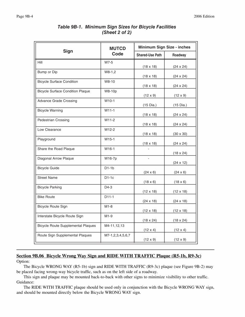
The minimum sign sizes for shared-use paths shall be those shown in Table 9B-1, and shall be usedonly for signs installed specifically for bicycle traffic applications. The minimum sign sizes for bicyclefacilities shall not be used for signs that are placed in a location that would have any application to othervehicles.Option:
Larger size signs may be used on bicycle facilities when appropriate.Guidance:
Except for size, the design of signs for bicycle facilities should be identical to that specified in this Manualfor vehicular travel. Support:
Uniformity in design includes shape, color, symbols, wording, lettering, and illumination or retroreflec-torization.
Section 9B.03 STOP and YIELD Signs (R1-1, R1-2)Standard:
STOP (R1-1) signs (see Figure 9B-2) shall be installed on shared-use paths at points where bicyclistsare required to stop.
YIELD (R1-2) signs (see Figure 9B-2) shall be installed on shared-use paths at points where bicyclistshave an adequate view of conflicting traffic as they approach the sign, and where bicyclists are required toyield the right-of-way to that conflicting traffic.Option:
A 30 x 30 inch STOP sign or a 36 x 36 x 36 inch YIELD sign may be used on shared-use paths for addedemphasis.Guidance:
Where conditions require path users, but not roadway users, to stop or yield, the STOP sign or YIELD signshould be placed or shielded so that it is not readily visible to road users.
When placement of STOP or YIELD signs is considered, priority at a shared-use path/roadway intersectionshould be assigned with consideration of the following:
2006 Edition Page 9B-1

A. Relative speeds of shared-use path and roadway users;B. Relative volumes of shared-use path and roadway traffic; andC. Relative importance of shared-use path and roadway.
Speed should not be the sole factor used to determine priority, as it is sometimes appropriate to give priorityto a high-volume shared-use path crossing a low-volume street, or to a regional shared-use path crossing a minorcollector street.
When priority is assigned, the least restrictive control that is appropriate should be placed on the lowerpriority approaches. STOP signs should not be used where YIELD signs would be acceptable.
Section 9B.04 Bicycle Lane Signs (R3-17, R3-17a, R3-17b)Standard:
The Bike Lane (R3-17) sign (see Figure 9B-2) shall be used only in conjunction with marked bicyclelanes as described in Section 9C.04, and shall be placed at periodic intervals along the bicycle lanes.Guidance:
The BIKE LANE (R3-17) sign spacing should be determined by engineering judgment based on prevailingspeed of bicycle and other traffic, block length, distances from adjacent intersections, and other considerations.
The AHEAD (R3-17a) sign (see Figure 9B-2) should be mounted directly below a R3-17 sign in advance ofthe beginning of a marked bicycle lane.
The ENDS (R3-17b) sign (see Figure 9B-2) should be mounted directly below a R3-17 sign at the end of amarked bicycle lane.
Section 9B.05 BEGIN RIGHT TURN LANE YIELD TO BIKES Sign (R4-4)Option:
Where motor vehicles entering an exclusive right-turn lane must weave across bicycle traffic in bicycle lanes,the BEGIN RIGHT TURN LANE YIELD TO BIKES (R4-4) sign (see Figure 9B-2) may be used to inform boththe motorist and the bicyclist of this weaving maneuver.Guidance:
The R4-4 sign should not be used when bicyclists need to move left because of a right-turn lane dropsituation.
Page 9B-2 2006 Edition
3 ft MIN.6 ft MAX.
4 ft
MIN
.5
ft M
AX
.
Width of shared-use path
3 ft MIN.6 ft MAX.
4 ft
MIN
.5
ft M
AX
.
Figure 9B-1. Sign Placement on Shared-Use Paths

2006 Edition Page 9B-3
Sign MUTCDCode
Minimum Sign Size - inches
Shared-Use Path Roadway
Stop R1-1 (18 x 18) (30 x 30)
Yield R1-2(18 x 18 x 18) (30 x 30 x 30)
Bike Lane R3-17 -(30 x 24)
Bicycle Lane Supplemental Plaques R3-17a,b -(30 x 12)
Movement Restriction R4-1,2,3,7(12 x 18) (18 x 24)
Begin Right Turn Lane Yield to Bikes R4-4 -(36 x 30)
Bicycle Wrong Way R5-1b (12 x 18) (12 x 18)
No Motor Vehicles R5-3(24 x 24) (24 x 24)
No Bicycles R5-6(24 x 24) (24 x 24)
No Parking Bike Lane R7-9,9a -(12 x 18)
Pedestrians Prohibited R9-3a(18 x 18) (18 x 18)
Ride With Traffic Plaque R9-3c (12 x 12) (12 x 12)
Bicycle Regulatory R9-5,6(12 x 18) (12 x 18)
Shared-Use Path Restriction R9-7 -(12 x 18)
Push Button for Green Light R10-3(9 x 12) (9 x 12)
To Request Green Wait on Symbol R10-22 (12 x 18) (12 x 18)
Railroad Crossbuck R15-1(24 x 4.5) (48 x 9)
Turn and Curve Warning W1-1,2,3,4,5(18 x 18) (24 x 24)
Arrow Warning W1-6,7(24 x 12) (36 x 18)
Intersection Warning W2-1,2,3,4,5(18 x 18) (24 x 24)
Stop,Yield,Signal Ahead W3-1,2,3(18 x 18) (30 x 30)
Narrow Bridge W5-2(18 x 18) (30 x 30)
Bikeway Narrows W5-4a(18 x 18) (30 x 30)
Table 9B-1. Minimum Sign Sizes for Bicycle Facilities(Sheet 1 of 2)
Page 9B-4 2006 Edition
Hill W7-5(18 x 18) (24 x 24)
Bump or Dip W8-1,2(18 x 18) (24 x 24)
Bicycle Surface Condition W8-10(18 x 18) (24 x 24)
Bicycle Surface Condition Plaque W8-10p(12 x 9) (12 x 9)
Advance Grade Crossing W10-1(15 Dia.) (15 Dia.)
Bicycle Warning W11-1(18 x 18) (24 x 24)
Pedestrian Crossing W11-2(18 x 18) (24 x 24)
Low Clearance W12-2(18 x 18) (30 x 30)
Playground W15-1(18 x 18) (24 x 24)
Share the Road Plaque W16-1 -(18 x 24)
Diagonal Arrow Plaque W16-7p -(24 x 12)
Bicycle Guide D1-1b(24 x 6) (24 x 6)
Street Name D1-1c(18 x 6) (18 x 6)
Bicycle Parking D4-3(12 x 18) (12 x 18)
Bike Route D11-1(24 x 18) (24 x 18)
Bicycle Route Sign M1-8(12 x 18) (12 x 18)
Interstate Bicycle Route Sign M1-9(18 x 24) (18 x 24)
Bicycle Route Supplemental Plaques M4-11,12,13(12 x 4) (12 x 4)
Route Sign Supplemental Plaques M7-1,2,3,4,5,6,7(12 x 9) (12 x 9)
Sign MUTCDCode
Minimum Sign Size - inches
Shared-Use Path Roadway
Table 9B-1. Minimum Sign Sizes for Bicycle Facilities(Sheet 2 of 2)
Section 9B.06 Bicycle Wrong Way Sign and RIDE WITH TRAFFIC Plaque (R5-1b, R9-3c)Option:
The Bicycle WRONG WAY (R5-1b) sign and RIDE WITH TRAFFIC (R9-3c) plaque (see Figure 9B-2) maybe placed facing wrong-way bicycle traffic, such as on the left side of a roadway.
This sign and plaque may be mounted back-to-back with other signs to minimize visibility to other traffic.Guidance:
The RIDE WITH TRAFFIC plaque should be used only in conjunction with the Bicycle WRONG WAY sign,and should be mounted directly below the Bicycle WRONG WAY sign.

2006 Edition Page 9B-5
R4-2R4-1 R4-3 R4-4 R4-7
R7-9 R7-9a
R5-6R5-3
R9-3c
R5-1b
R1-1 R1-2
R9-6R9-5 R10-3
R15-1
R9-7
R9-3a
R3-17a
R3-17bR3-17
Figure 9B-2. Regulatory Signs for Bicycle Facilities
R10-22

Section 9B.07 NO MOTOR VEHICLES Sign (R5-3)Option:
The NO MOTOR VEHICLES (R5-3) sign (see Figure 9B-2) may be installed at the entrance to a shared-usepath.
Section 9B.08 No Bicycles Sign (R5-6)Guidance:
Where bicyclists are prohibited, the No Bicycles (R5-6) sign (see Figure 9B-2) should be installed at theentrance to the facility.Option:
Where pedestrians and motor-driven cycles are also prohibited, it may be more desirable to use the R5-10aword message sign that is described in Section 2B.36.
Section 9B.09 No Parking Bike Lane Signs (R7-9, R7-9a)Standard:
If the installation of signs is necessary to restrict parking, standing, or stopping in a bicycle lane,appropriate signs as described in Sections 2B.39 through 2B.41, or the No Parking Bike Lane (R7-9 or R7-9a) signs (see Figure 9B-2) shall be installed.
Section 9B.10 Bicycle Regulatory Signs (R9-5, R9-6, R10-3)Option:
The R9-5 sign (see Figure 9B-2) may be used where the crossing of a street by bicyclists is controlled bypedestrian signal indications.
Where it is not intended for bicyclists to be controlled by pedestrian signal indications, the R10-3 sign (seeFigure 9B-2 and Section 2B.45) may be used.
The R9-6 sign (see Figure 9B-2) may be used where a bicyclist is required to cross or share a facility used bypedestrians and is required to yield to the pedestrians.Guidance:
If used, the R9-5 or R10-3 signs should be installed near the edge of the sidewalk in the vicinity of wherebicyclists will be crossing the street.
Section 9B.11 Shared-Use Path Restriction Sign (R9-7)Option:
The Shared-Use Path Restriction (R9-7) sign (see Figure 9B-2) may be installed on facilities that are to beshared by pedestrians and bicyclists. The symbols may be switched as appropriate.
A designated pavement area may be provided for each mode of travel (see Section 9C.03).
Section 9B.12 Bicycle Signal Actuation Sign (R10-22)Option:
The Bicycle Signal Actuation (R10-22) sign (see Figure 9B-2) may be installed at signalized intersectionswhere markings are used to indicate the location where a bicyclist is to be positioned to actuate the signal (seeSection 9C.05).Guidance:
If the Bicycle Signal Actuation sign is installed, it should be placed at the roadside adjacent to the marking toemphasize the connection between the marking and the sign.
Section 9B.13 Other Regulatory SignsOption:
Other regulatory signs described in Chapter 2B may be installed on bicycle facilities as appropriate.
Section 9B.14 Turn or Curve Warning Signs (W1 Series)Guidance:
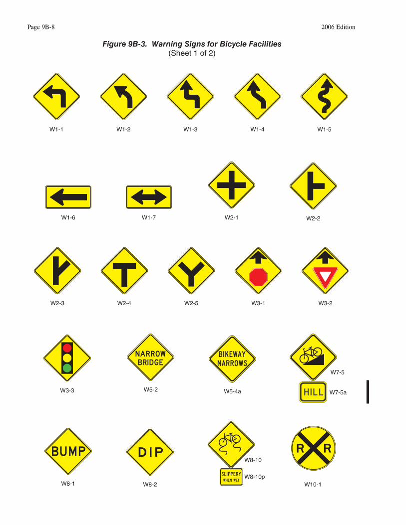
To warn bicyclists of unexpected changes in shared-use path direction, appropriate turn or curve (W1-1through (W1-7) signs (see Figure 9B-3) should be used.
The W1-1 through W1-5 signs should be installed no less than 50 ft. in advance of the beginning of thechange of alignment.
Page 9B-6 2006 Edition

Section 9B.15 Intersection Warning Signs (W2 Series)Option:
Intersection Warning (W2-1 through W2-5) signs (see Figure 9B-3) may be used on a roadway, street, orshared-use path in advance of an intersection to indicate the presence of an intersection and the possibility ofturning or entering traffic.Guidance:
When engineering judgment determines that the visibility of the intersection is limited on the shared-use pathapproach, Intersection Warning signs should be used.
Intersection Warning signs should not be used where the shared-use path approach to the intersection iscontrolled by a STOP sign, YIELD sign, or a traffic control signal.
Section 9B.16 Bicycle Surface Condition Warning Sign (W8-10)Option:
The Bicycle Surface Condition Warning (W8-10) sign (see Figure 9B-3) may be installed where roadway or shared-use path conditions could cause a bicyclist to lose control of the bicycle. The educational plaque (W8-10p) may be placed below the W8-10 sign.
Signs warning of other conditions that might be of concern to bicyclists, including BUMP (W8-1), DIP (W8-2), PAVEMENT ENDS (W8-3), and any other word message that describes conditions that are of concern to bicyclists, may also be used.
A supplemental plaque may be used to clarify the specific type of surface condition.
Section 9B.17 Bicycle Warning Sign (W11-1)Support:
The Bicycle Warning (W11-1) sign (see Figure 9B-3) alerts the road user to unexpected entries into theroadway by bicyclists, and other crossing activities that might cause conflicts. These conflicts might berelatively confined, or might occur randomly over a segment of roadway.Option:
A supplemental plaque with the legend AHEAD or XXX FEET may be used with the Bicycle Warning sign.Guidance:
If used in advance of a specific crossing point, the Bicycle Warning sign should be placed at a distance inadvance of the crossing location that conforms with the guidance given in Table 2C-4.Standard:
Bicycle Warning signs, when used at the location of the crossing, shall be supplemented with adiagonal downward pointing arrow (W16-7p) plaque (see Figure 9B-3) to show the location of the crossing.Option:
A fluorescent yellow-green background color with a black legend and border may be used for BicycleWarning signs and supplemental plaques.Guidance:
When the fluorescent yellow-green background color is used, a systematic approach featuring onebackground color within a zone or area should be used. The mixing of standard yellow and fluorescent yellow-green backgrounds within a zone or area should be avoided.
Section 9B.18 Other Bicycle Warning SignsOption:
Other bicycle warning signs (see Figure 9B-3) such as BIKEWAY NARROWS (W5-4a) and Hill (W7-5)may be installed on bicycle facilities to warn bicyclists of conditions not readily apparent. The educationalplaque (W7-5a) may be placed below the W7-5 sign.
In situations where there is a need to warn motorists to watch for bicyclists traveling along the highway, theSHARE THE ROAD (W16-1) plaque (see Figure 9B-3) may be used in conjunction with the W11-1 sign.Guidance:
If used, other advance bicycle warning signs should be installed no less than 50 ft. in advance of thebeginning of the condition.
Where temporary traffic control zones are present on bikeways, appropriate signs from Part 6 should be used.
2006 Edition Page 9B-7
Page 9B-8 2006 Edition
W1-1 W1-2 W1-3 W1-4 W1-5
W2-4 W2-5 W3-1 W3-2W2-3
W5-2W3-3 W5-4a
W7-5
W7-5a
W2-1 W2-2W1-7W1-6
W8-1 W8-2 W10-1
W8-10
W8-10p
Figure 9B-3. Warning Signs for Bicycle Facilities(Sheet 1 of 2)

Option:Other warning signs described in Chapter 2C may be installed on bicycle facilities as appropriate.
Section 9B.19 Bicycle Route Guide Signs (D11-1)Guidance:
If used, Bicycle Route Guide (D11-1) signs (see Figure 9B-4) should be provided at decision points alongdesignated bicycle routes, including signs to inform bicyclists of bicycle route direction changes andconfirmation signs for route direction, distance, and destination.
If used, Bicycle Route Guide signs should be repeated at regular intervals so that bicyclists entering fromside streets will have an opportunity to know that they are on a bicycle route. Similar guide signing should beused for shared roadways with intermediate signs placed for bicyclist guidance.Support:
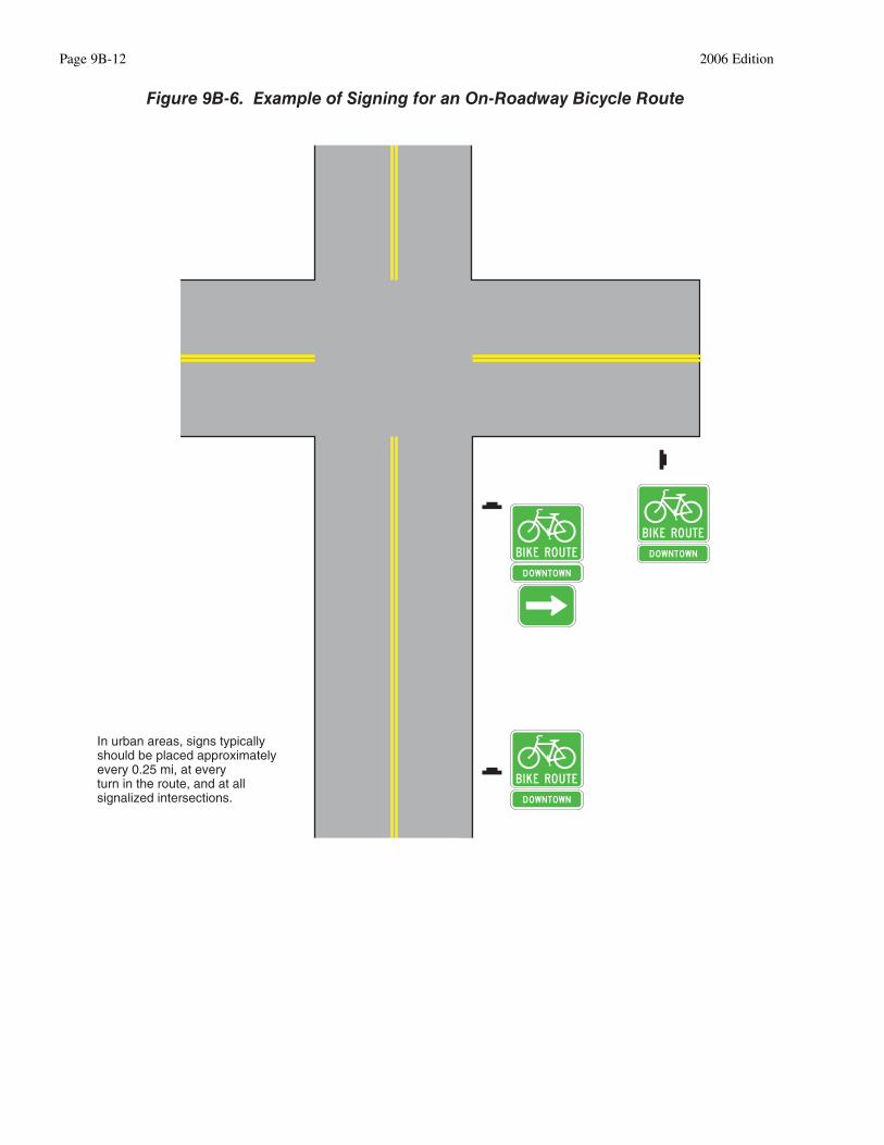
Figure 9B-5 shows an example of the signing for the beginning and end of a designated bicycle route on ashared-use path. Figure 9B-6 shows an example of signing for an on-roadway bicycle route. Figure 9B-7 showsexamples of signing and markings for shared-use paths.
Section 9B.20 Bicycle Route Signs (M1-8, M1-9)Option:
To establish a unique identification (route designation) for a State or local bicycle route, the Bicycle Route(M1-8) sign (see Figure 9B-4) may be used.Standard:
The Bicycle Route sign shall contain a route designation and shall have a green background with aretroreflectorized white legend and border.
2006 Edition Page 9B-9
(Sheet 2 of 2)
Figure 9B-3. Warning Signs for Bicycle Facilities
W11-2
W15-1W12-2
W11-1
W11-1
W16-1
W16-7p
W11-1

Option:Where a designated bicycle route extends for long distances through two or more States, a coordinated
submittal by the affected States for an assignment of an Interstate Bicycle Route number designation may be sentto the American Association of State Highway and Transportation Officials (see Page i for the address).Standard:
The Interstate Bicycle Route (M1-9) sign (see Figure 9B-4) shall contain the assigned route numberdesignation and have a black legend and border with a retroreflectorized white background.Guidance:
If used, the Bicycle Route or Interstate Bicycle Route signs should be placed at intervals frequent enough tokeep bicyclists informed of changes in route direction and to remind motorists of the presence of bicyclists.Option:
Bicycle Route or Interstate Bicycle Route signs may be installed on shared roadways or on shared-use pathsto provide guidance for bicyclists.
The Bicycle Route Guide (D11-1) sign (see Figure 9B-4) may be installed where no unique designation ofroutes is desired.
Section 9B.21 Destination Arrow and Supplemental Plaque Signs for Bicycle Route SignsOption:
Destination (D1-1b and D1-1c) signs (see Figure 9B-4) may be mounted below Bicycle Route Guide signs,Bicycle Route signs, or Interstate Bicycle Route signs to furnish additional information, such as directionalchanges in the route, or intermittent distance and destination information.
The M4-11 through M4-13 supplemental plaques (see Figure 9B-4) may be mounted above the appropriateBicycle Route Guide signs, Bicycle Route signs, or Interstate Bicycle Route signs.
Page 9B-10 2006 Edition
Figure 9B-4. Guide Signs for Bicycle Facilities
M7-2 M7-3 M7-4 M7-6M7-5 M7-7
M4-11 M4-12 M4-13M7-1
M1-9
D4-3 M1-8D1-1L
D1-1R
D3-1 D11-1
* See "Standard Highway Sign Design" manual for M7 series regulatory.

2006 Edition Page 9B-11
Varies- seeSection 9B.17
Varies- seeSection 9B.17
(optional)
Shared-Use Path
100 ft
Roadway
(optional)
Figure 9B-5. Example of Signing for the Beginning and Endof a Designated Bicycle Route on a Shared-Use Path
Page 9B-12 2006 Edition
Figure 9B-6. Example of Signing for an On-Roadway Bicycle Route
In urban areas, signs typically should be placed approximatelyevery 0.25 mi, at every turn in the route, and at all signalized intersections.

2006 Edition Page 9B-13
Figure 9B-7. Examples of Signing and Markings for Shared-Use Paths
Crosswalk linesas needed
Varies- see Section 9B.17
(optional)
Intersection traffic control devices as warrantedon either facility depending on conditions
(see Section 9B.03)
100 ft
Roadway
Shared-Use Path
4 ft
5 ft
4 ft
50 ft
8 ft 32 ft 8 ft
Shared-Use Path50 ft
50 ft
15 ft
(if no stop, yield, orsignal control on path)

Guidance:If used, the appropriate arrow (M7-1 through M7-7) sign (see Figure 9B-4) should be placed below the
Bicycle Route Guide sign, Bicycle Route sign, or Interstate Bicycle Route sign.Standard:
The arrow signs and supplemental plaques used with the D11-1 or M1-8 signs shall have a whitelegend and border on a green background.
The arrow signs and supplemental plaques used with the M1-9 sign shall have a white legend andborder on a black background.
Section 9B.22 Bicycle Parking Area Sign (D4-3)Option:
The Bicycle Parking Area (D4-3) sign (see Figure 9B-4) may be installed where it is desirable to show thedirection to a designated bicycle parking area. The arrow may be reversed as appropriate.Standard:
The legend and border of the Bicycle Parking Area sign shall be green on a retroreflectorized whitebackground.
Page 9B-14 2006 Edition

CHAPTER 9C. MARKINGS
Section 9C.01 Functions of MarkingsSupport:
Markings indicate the separation of the lanes for road users, assist the bicyclist by indicating assigned travelpaths, indicate correct position for traffic control signal actuation, and provide advance information for turningand crossing maneuvers.
Section 9C.02 General PrinciplesGuidance:
Bikeway design guides should be used when designing markings for bicycle facilities (see Section 9A.05).Standard:
Markings used on bikeways shall be retroreflectorized.Guidance:
Pavement marking symbols and/or word messages should be used in bikeways where appropriate.Consideration should be given to selecting pavement marking materials that will minimize loss of traction forbicycles under wet conditions.Standard:
The colors, width of lines, patterns of lines, and symbols used for marking bicycle facilities shall be asdefined in Sections 3A.04, 3A.05, and 3B.22.Support:
Figures 9B-7 and 9C-1 through 9C-8 show examples of the application of lines, word messages, and symbolson designated bikeways.Option:
A dotted line may be used to define a specific path for a bicyclist crossing an intersection (see Figure 9C-1)as described in Sections 3A.05 and 3B.08.
Section 9C.03 Marking Patterns and Colors on Shared-Use PathsOption:
Where shared-use paths are of sufficient width to designate two minimum width lanes, a solid yellow linemay be used to separate the two directions of travel where passing is not permitted, and a broken yellow linemay be used where passing is permitted (see Figure 9C-2).Guidance:
Broken lines used on shared-use paths should have the usual 1-to-3 segment-to-gap ratio. A nominal 3 ft.segment with a 9 ft. gap should be used.
If conditions make it desirable to separate two directions of travel on shared-use paths at particular locations,a solid yellow line should be used to indicate no passing and no traveling to the left of the line.
Markings as shown in Figure 9C-2 should be used at the location of obstructions in the center of the path,including vertical elements intended to physically prevent unauthorized motor vehicles from entering the path.Option:
A solid white line may be used on shared-use paths to separate different types of users. The R9-7 sign (seeFigure 9B-2) may be used to supplement the solid white line.
Smaller size letters and symbols may be used on shared-use paths. Where arrows are needed on shared-usepaths, half-size layouts of the arrows may be used (see Section 3B.19).
2006 Edition Page 9C-1

Page 9C-2 2006 Edition
Dotted linesare optinal
Dotted linesare optinal
Not less than 50 ft
Figure 9C-1. Example of Intersection Pavement Markings—DesignatedBicycle Lane with Left-Turn Area, Heavy Turn Volumes, Parking,
One-Way Traffic, or Divided Highway

2006 Edition Page 9C-3
10 ft 1 ft
Obstruction Normal solid yellow line
9 ft
3 ft
Normalbrokenyellow
line
Passing permitted
Normalsolid
yellowline
Passing NOT permitted
Figure 9C-2. Examples of Centerline Markings for Shared-Use Paths

Fixed objects adjacent to shared-use paths may be marked with object markers (Type 1, 2, or 3).Standard:
All object markers shall be retroreflective.Markers such as those described in Section 3C.01 shall also be used on shared-use paths, if needed.Obstructions in the traveled way of a shared-use path shall be marked with retroreflectorized material
or appropriate object markers.On Type 3 markers, the alternating black and retroreflective yellow stripes shall be sloped down at an
angle of 45 degrees toward the side on which traffic is to pass the obstruction.
Section 9C.04 Markings For Bicycle LanesGuidance:
Longitudinal pavement markings should be used to define bicycle lanes.Support:
Pavement markings designate that portion of the roadway for preferential use by bicyclists. Markings informall road users of the restricted nature of the bicycle lane.
Examples of bicycle lane markings at right-turn lanes are shown in Figures 9C-1, 9C-3, and 9C-4. Examplesof pavement markings for bicycle lanes on a two-way street are shown in Figure 9C-5. Pavement symbols andmarkings for bicycle lanes are shown in Figure 9C-6.Standard:
If used, the bicycle lane symbol marking (see Figure 9C-6) shall be placed immediately after anintersection and at other locations as needed. The bicycle lane symbol marking shall be white. If thebicycle lane symbol marking is used in conjunction with other word or symbol messages, it shall precedethem.
If the word or symbol pavement markings shown in Figure 9C-6 are used, Bicycle Lane signs (seeSection 9B.04) shall also be used, but the signs need not be adjacent to every symbol to avoid overuse ofthe signs.
A through bicycle lane shall not be positioned to the right of a right turn only lane.Support:
A bicyclist continuing straight through an intersection from the right of a right turn lane would beinconsistent with normal traffic behavior and would violate the expectations of right-turning motorists.Guidance:
When the right through lane is dropped to become a right turn only lane, the bicycle lane markings shouldstop at least 100 ft. before the beginning of the right turn lane. Through bicycle lane markings should resume tothe left of the right turn only lane.
An optional through-right turn lane next to a right turn only lane should not be used where there is a throughbicycle lane. If a capacity analysis indicates the need for an optional through-right turn lane, the bicycle laneshould be discontinued at the intersection approach.
Posts or raised pavement markers should not be used to separate bicycle lanes from adjacent travel lanes.Support:
Using raised devises creates a collision potential for bicyclists by placing fixed objects immediately adjacentto the travel path of the bicyclist. In addition, raised devices can prevent vehicles turning right from mergingwith the bicycle lane, which is the preferred method for making the right turn. Raised devices used to define abicycle lane can also cause problems in cleaning and maintaining the bicycle lane.Standard:
Bicycle lanes shall not be provided on the circular roadway of a roundabout intersection.
Section 9C.05 Bicycle Detector SymbolOption:
A symbol (see Figure 9C-7) may be placed on the pavement indicating the optimum position for a bicyclistto actuate the signal.
An R10-22 sign (see Section 9B.12 and Figure 9B-2) may be installed to supplement the pavement marking.
Page 9C-4 2006 Edition

2006 Edition Page 9C-5
Dotted linesare optional
At beginning ofright turn only lane
Figure 9C-3. Example of Bicycle Lane Treatment at a Right Turn Only Lane

Page 9C-6 2006 Edition
Dotted linesare optional
At beginning ofright turn only lane
Figure 9C-4. Example of Bicycle Lane Treatment at Parking Laneinto a Right Turn Only Lane

2006 Edition Page 9C-7
Figure 9C-5. Example of Pavement Markings for Bicycle Laneson a Two-Way Street
Exa
mp
le o
f ap
plic
atio
n w
her
e p
arki
ng
is p
roh
ibite
d
Normal solid white line
Exa
mp
le o
f ap
plic
atio
n w
her
e p
arki
ng
is p
erm
itted
50-200 ftdotted line if bus stopor heavyright-turn volume
R7 series sign(as appropriate)
Normal solidwhite line
Optional normalsolid white line
50-200 ftdotted line -2 ft line,6 ft space
Dotted line for bus stopsimmediately beyond theintersection is optional;
otherwise use normalsolid white line
R7 series sign(as appropriate)
Signalized intersection
Minor intersection

Page 9C-8 2006 Edition
Directional arrow
Symbols Word Legends(optional)
= 4 in x 4 in
Normal white line
6 ft(optional)
6 ft
6 ft
Figure 9C-6. Example of Optional Word and Symbol Pavement Markingsfor Bicycle Lanes
Section 9C.06 Pavement Markings for ObstructionsGuidance:
In roadway situations where it is not practical to eliminate a drain grate or other roadway obstruction that isinappropriate for bicycle travel, white markings applied as shown in Figure 9C-8 should be used.

2006 Edition Page 9C-9
6 in
5 in
24 in
2 in
6 in
Figure 9C-7. Example of Bicycle Detector Pavement Marking
L = WS , where S is bicycle approach speed in miles per hour
Direction of bicycle travel
W
Pier, abutment, grate, or other obstruction
Wide solid white line (see Section 3A.06)
Figure 9C-8. Example of Obstruction Pavement Marking

Page 9C-10 2006 Edition
CHAPTER 9D. SIGNALS
Section 9D.01 ApplicationSupport:
Part 4 contains information regarding signal warrants and other requirements relating to signal installations.Option:
For purposes of signal warrant evaluation, bicyclists may be counted as either vehicles or pedestrians.
Section 9D.02 Signal Operations for BicyclesStandard:
At installations where visibility-limited signal faces are used, signal faces shall be adjusted so bicyclistsfor whom the indications are intended can see the signal indications. If the visibility-limited signal facescannot be aimed to serve the bicyclist, then separate signal faces shall be provided for the bicyclist.
On bikeways, signal timing and actuation shall be reviewed and adjusted to consider the needs ofbicyclists.
2006 Edition Page 9D-1

Page 9D-2 2006 Edition


