• Part-C Main topics B1- Electronics cooling methods in industry • Heat sinks and cold plates for electronic cooling "Heat sinks" • Heat pipes in electronic cooling • Thermoelectric cooling • Immersion cooling • Cooling techniques for high density electronics
Transcript
• Part-C Main topics
B1- Electronics cooling methods in industry
• Heat sinks and cold plates for electronic cooling "Heat sinks"
• Heat pipes in electronic cooling• Thermoelectric cooling• Immersion cooling• Cooling techniques for high density electronics
Heat sinks
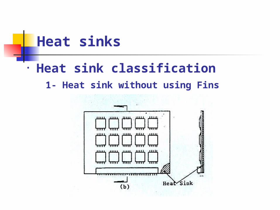
• Heat sink classification 1- Heat sink without using Fins
Heat sink classification
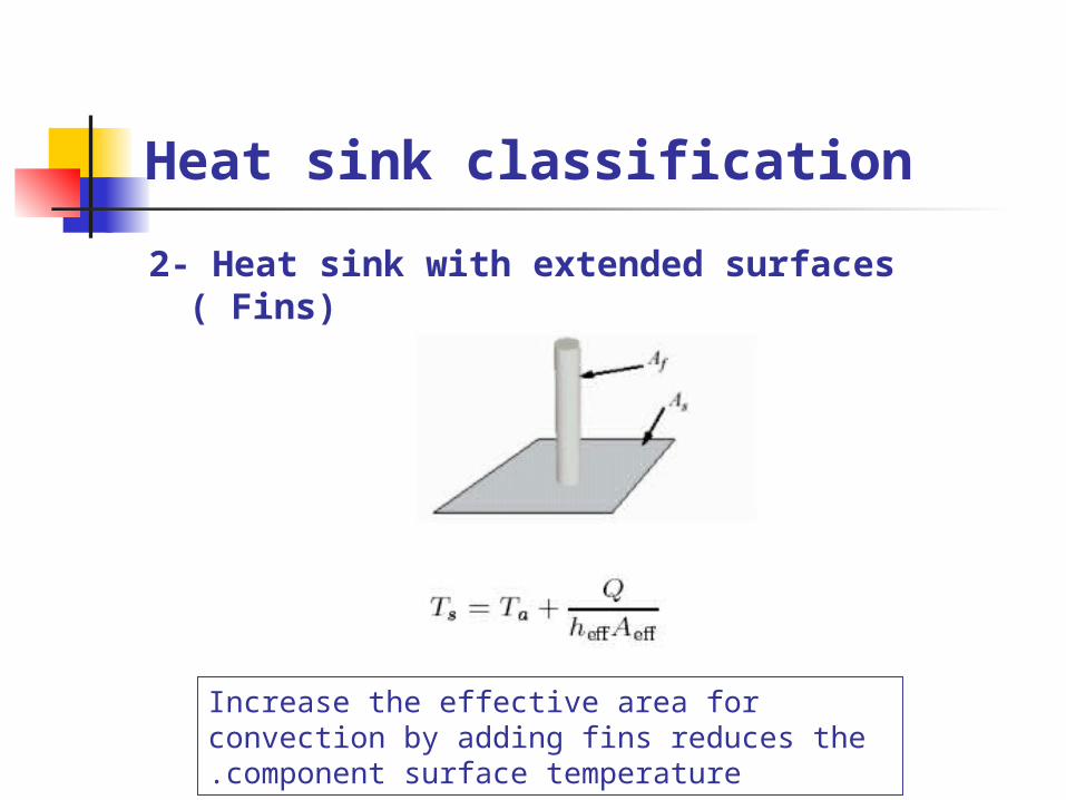
2- Heat sink with extended surfaces ( Fins)
Increase the effective area for convection by adding fins reduces the component surface temperature.
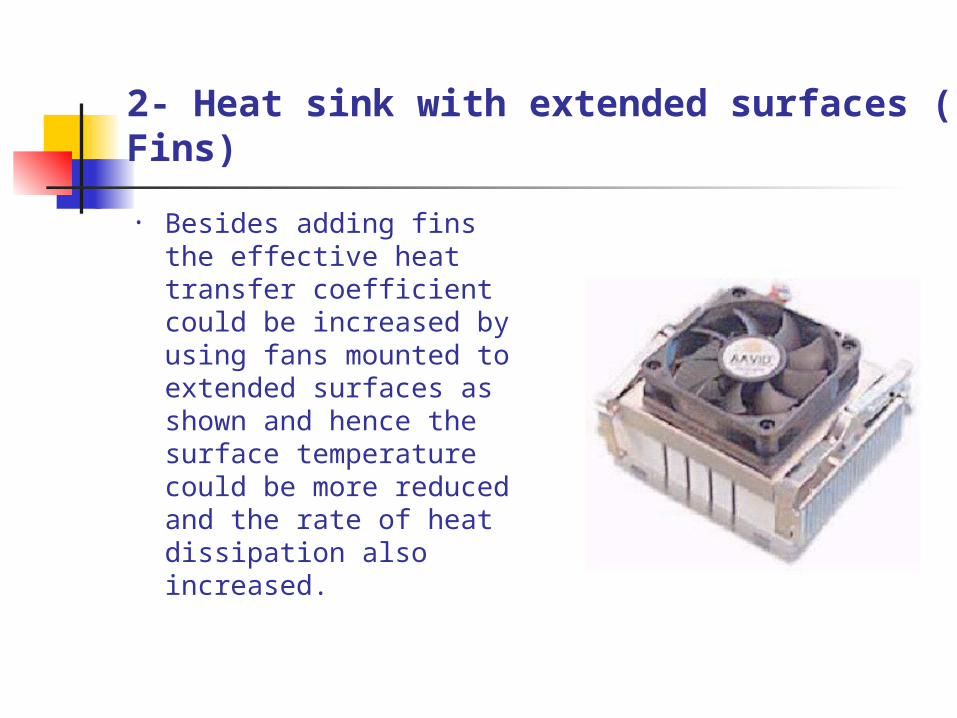
2- Heat sink with extended surfaces ( Fins)
• Besides adding fins the effective heat transfer coefficient could be increased by using fans mounted to extended surfaces as shown and hence the surface temperature could be more reduced and the rate of heat dissipation also increased.
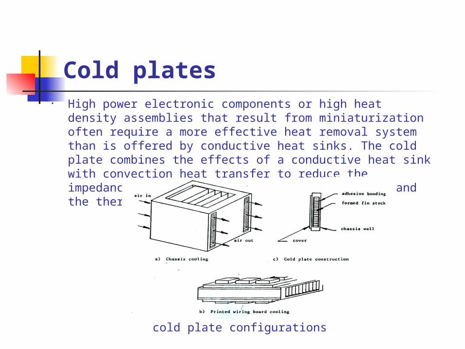
Cold plates• High power electronic components or high heat density
assemblies that result from miniaturization often require a more effective heat removal system than is offered by conductive heat sinks. The cold plate combines the effects of a conductive heat sink with convection heat transfer to reduce the impedances between the generating heat sources and the thermal sink.
cold plate configurations
Heat sink attachment
1-Mechanical attachment Mechanical attachment generally consists of
screws or clips that affix the heat sink directly to the device or to the PCB. The issues to consider here are the interface between the heat sink and the device, the number and type of parts needed, and the stresses imparted to the PCB and the device.
2-Adhesive attachment Adhesive attachment is accomplished with
double-sided tapes or dispensed adhesives such as epoxies.
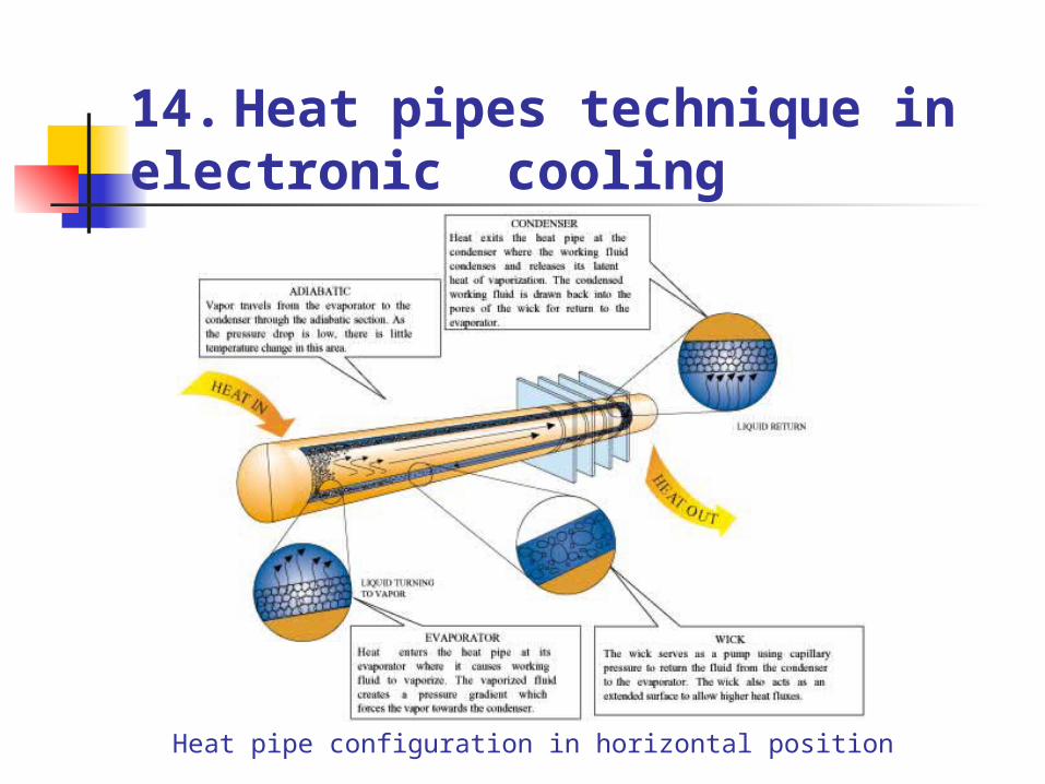
14. Heat pipes technique in electronic cooling
Heat pipe configuration in horizontal position
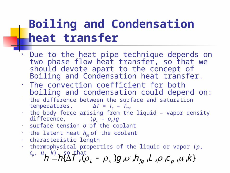
Boiling and Condensation heat transfer
• Due to the heat pipe technique depends on two phase flow heat transfer, so that we should devote apart to the concept of Boiling and Condensation heat transfer.
• The convection coefficient for both boiling and condensation could depend on:
- the difference between the surface and saturation temperatures, ΔT = Ts – Tsat
- the body force arising from the liquid – vapor density difference, (ρL – ρv)g
- surface tension σ of the coolant - the latent heat hfg of the coolant - characteristic length - thermophysical properties of the liquid or vapor (ρ, cp, μ, k), so
that },,,,,,,)(,{ kcLhgThh pfgL
Boiling heat transfer
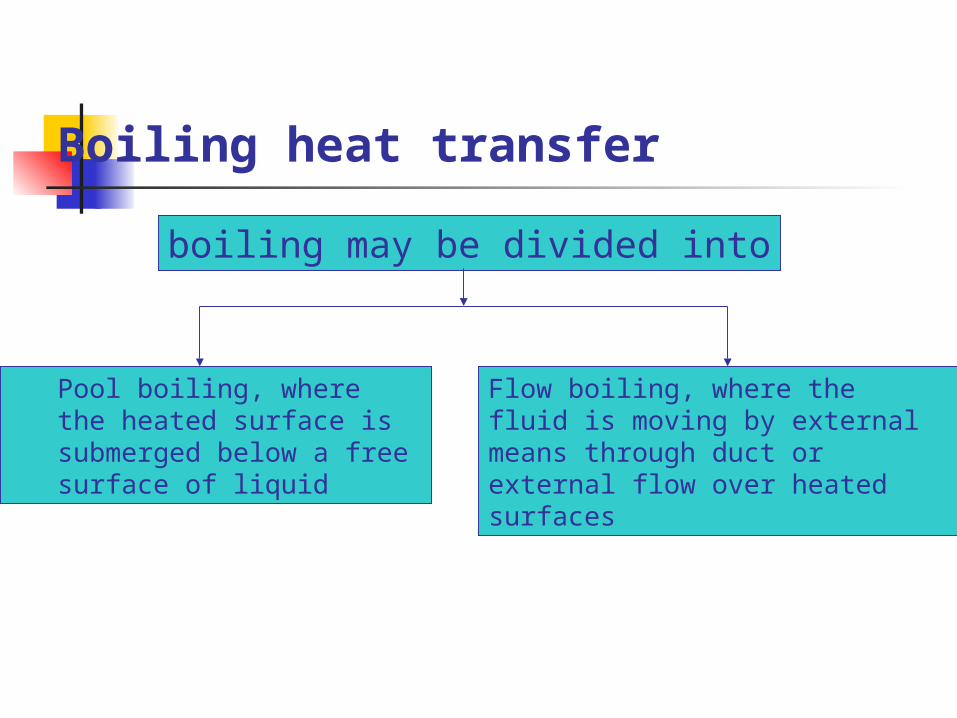
boiling may be divided into
Pool boiling, where the heated surface is submerged below a free surface of liquid
Flow boiling, where the fluid is moving by external means through duct or external flow over heated surfaces
Condensation
Condensation may be divided into
Dropwise condensation
Film condensation
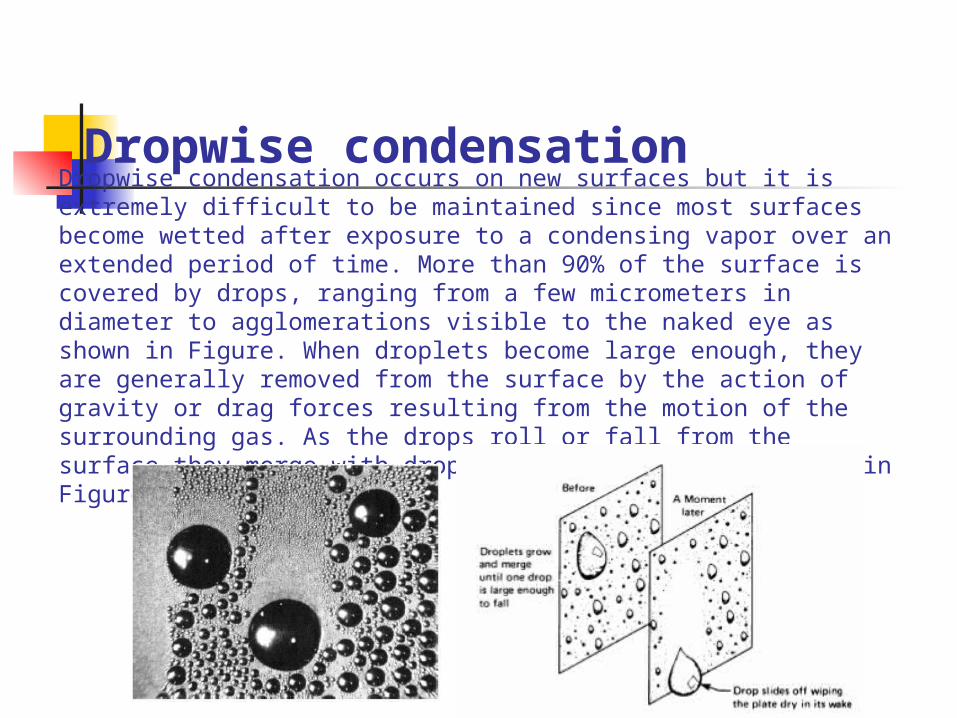
Dropwise condensation Dropwise condensation occurs on new surfaces but it is extremely difficult to be maintained since most surfaces become wetted after exposure to a condensing vapor over an extended period of time. More than 90% of the surface is covered by drops, ranging from a few micrometers in diameter to agglomerations visible to the naked eye as shown in Figure. When droplets become large enough, they are generally removed from the surface by the action of gravity or drag forces resulting from the motion of the surrounding gas. As the drops roll or fall from the surface they merge with droplets in their path as shown in Figure.
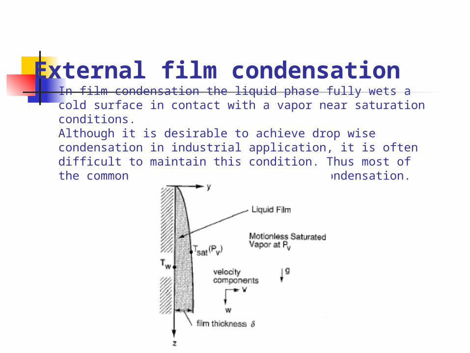
External film condensation In film condensation the liquid phase fully wets a cold surface in contact with a vapor near saturation conditions. Although it is desirable to achieve drop wise condensation in industrial application, it is often difficult to maintain this condition. Thus most of the common designs are based on film condensation.
15. Heat pipes in electronic cooling (cont.)
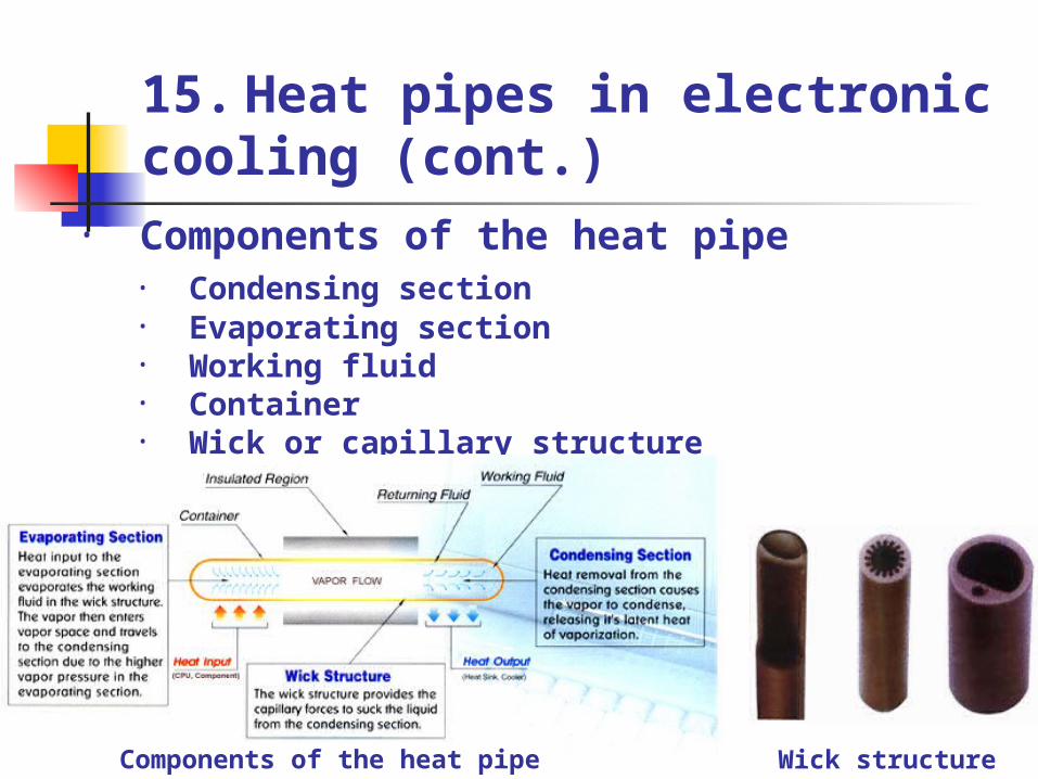
• Condensing section• Evaporating section• Working fluid• Container • Wick or capillary structure
• Components of the heat pipe
Components of the heat pipe Wick structure
Features of heat pipes2- Low relative weight3- Reliable in operation4- Flexible
Some flexible heat pipes
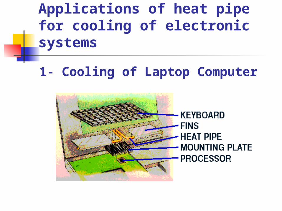
Applications of heat pipe for cooling of electronic systems
1- Cooling of Laptop Computer
Applications of heat pipe for cooling of electronic systems
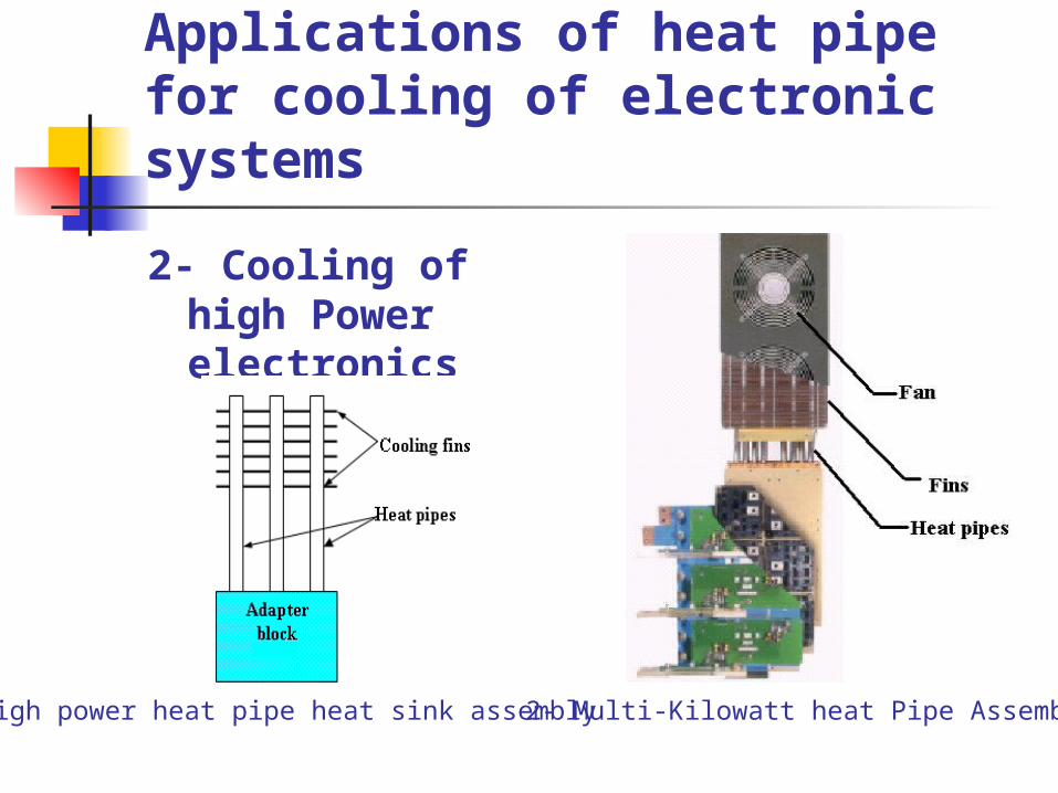
2- Cooling of high Power electronics
1- High power heat pipe heat sink assembly 2- Multi-Kilowatt heat Pipe Assembly
2- Thermosyphons system
• Thermosyphons transfer heat in exactly the same way as the Heat Pipe by evaporation followed by condensation. However no capillary structure is present to aid liquid transport from the condenser back to the evaporator, and thus the evaporator must be located vertically below the condenser, gravity will then ensure that the condensatereturns to the evaporator.
• To avoid the confusion because the term "Heat Pipe" is commonly used to describe both the Heat Pipe and Thermosyphone the term "Gravity Assisted Heat Pipe" has been used to describe Thermosyphons.
17. Thermoelectric cooling (TEC)
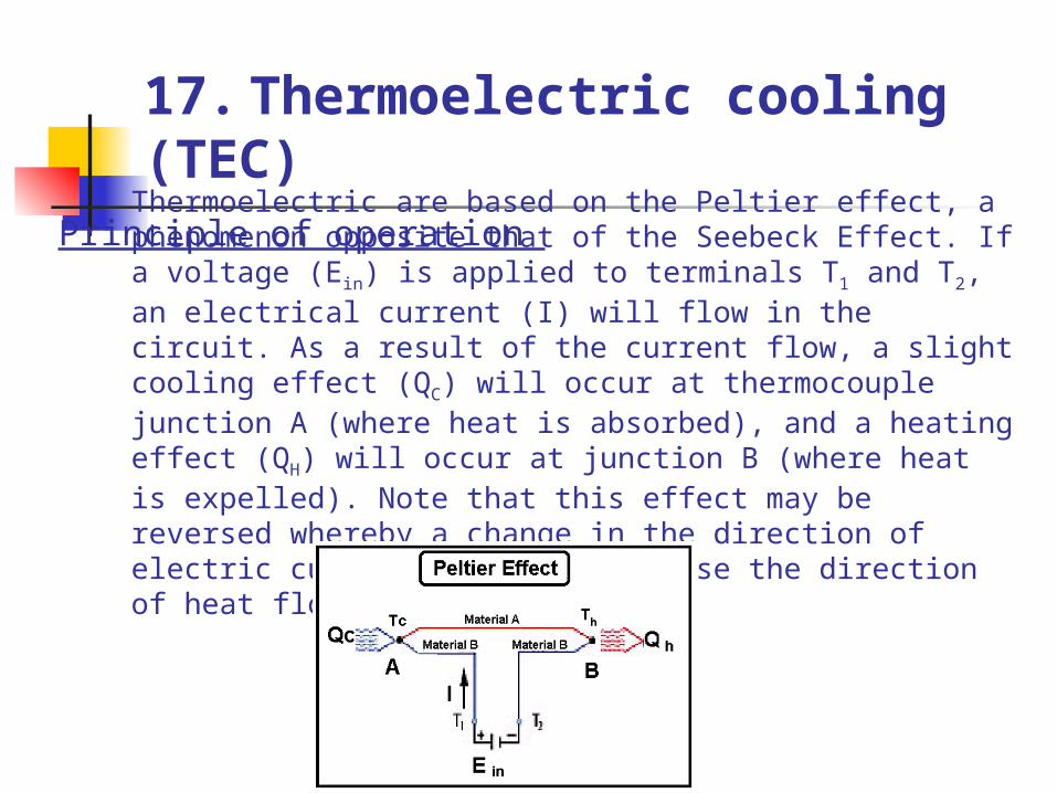
Thermoelectric are based on the Peltier effect, a phenomenon opposite that of the Seebeck Effect. If a voltage (Ein) is applied to terminals T1 and T2, an electrical current (I) will flow in the circuit. As a result of the current flow, a slight cooling effect (QC) will occur at thermocouple junction A (where heat is absorbed), and a heating effect (QH) will occur at junction B (where heat is expelled). Note that this effect may be reversed whereby a change in the direction of electric current flow will reverse the direction of heat flow.
Principle of operation
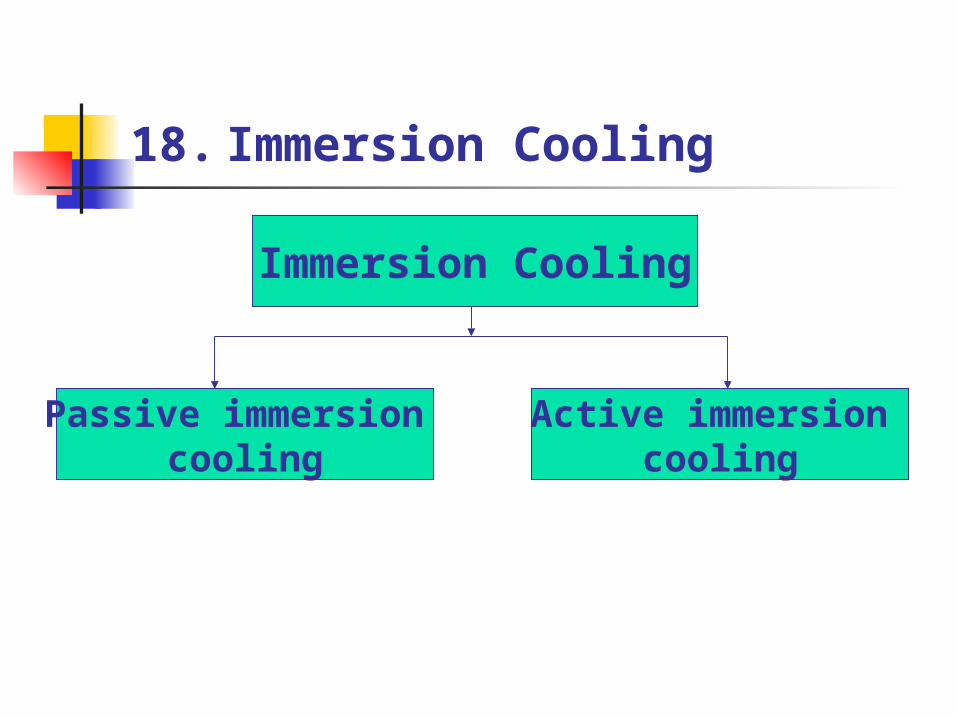
18. Immersion Cooling
Immersion Cooling
Passive immersion cooling
Active immersion cooling
Advantage and Limitation • Advantages: - Very wide operating temperature range. - Able to handle much larger heat loads than other
methods.
- Absolutely silent. • Disadvantages: - Suitable dielectric fluid may be expensive. - Hardware upgrades are made difficult, since the
module must be opened and drained to access the components.
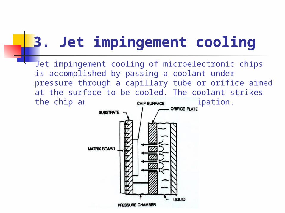
3. Jet impingement cooling• Jet impingement cooling of microelectronic chips is
accomplished by passing a coolant under pressure through a capillary tube or orifice aimed at the surface to be cooled. The coolant strikes the chip and absorbs its heat dissipation.
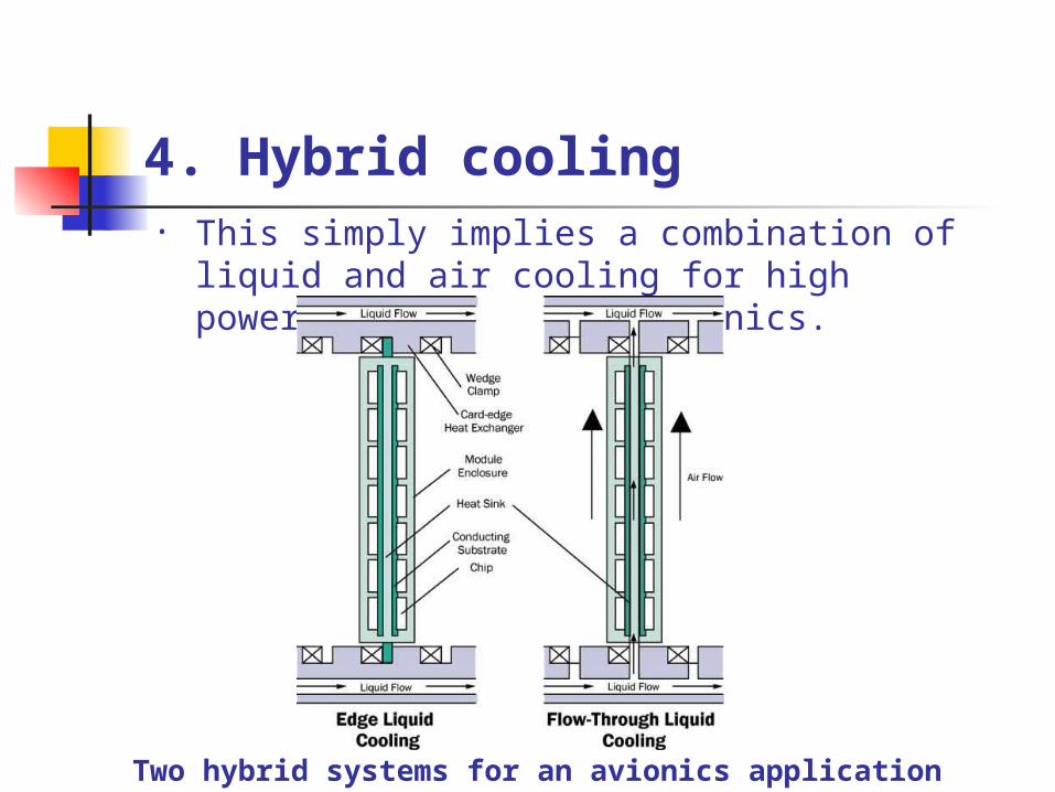
4. Hybrid cooling • This simply implies a combination of liquid
and air cooling for high power dissipation electronics.
Two hybrid systems for an avionics application
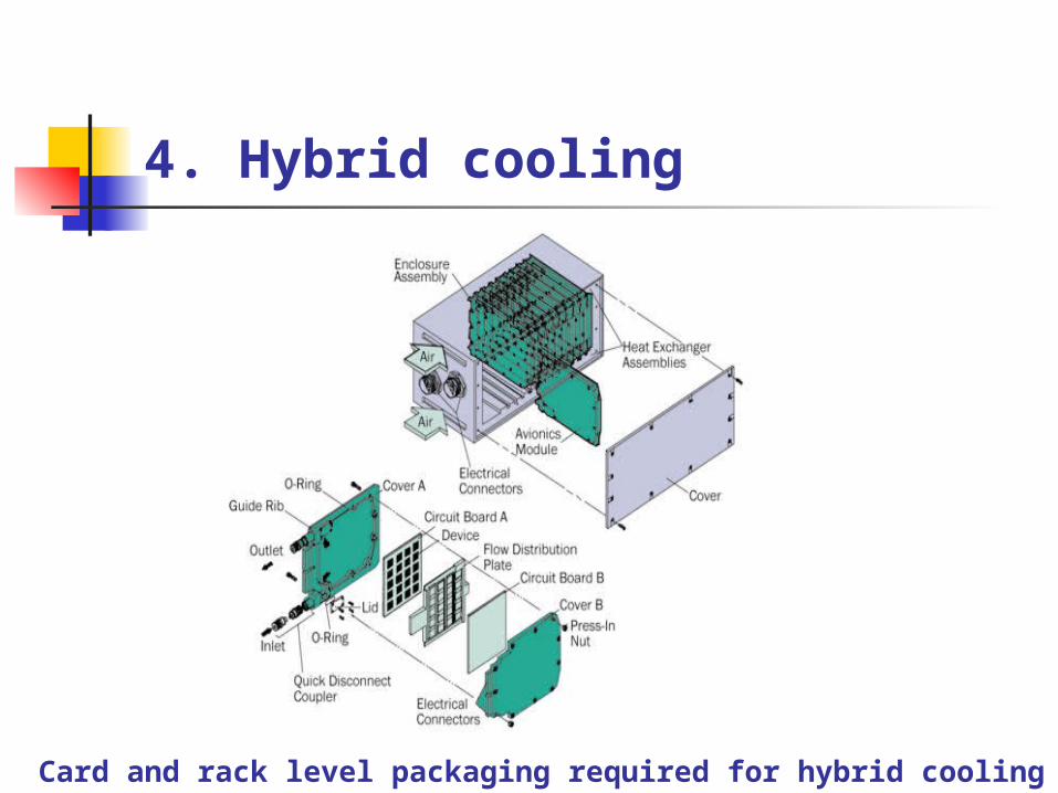
4. Hybrid cooling
Card and rack level packaging required for hybrid cooling
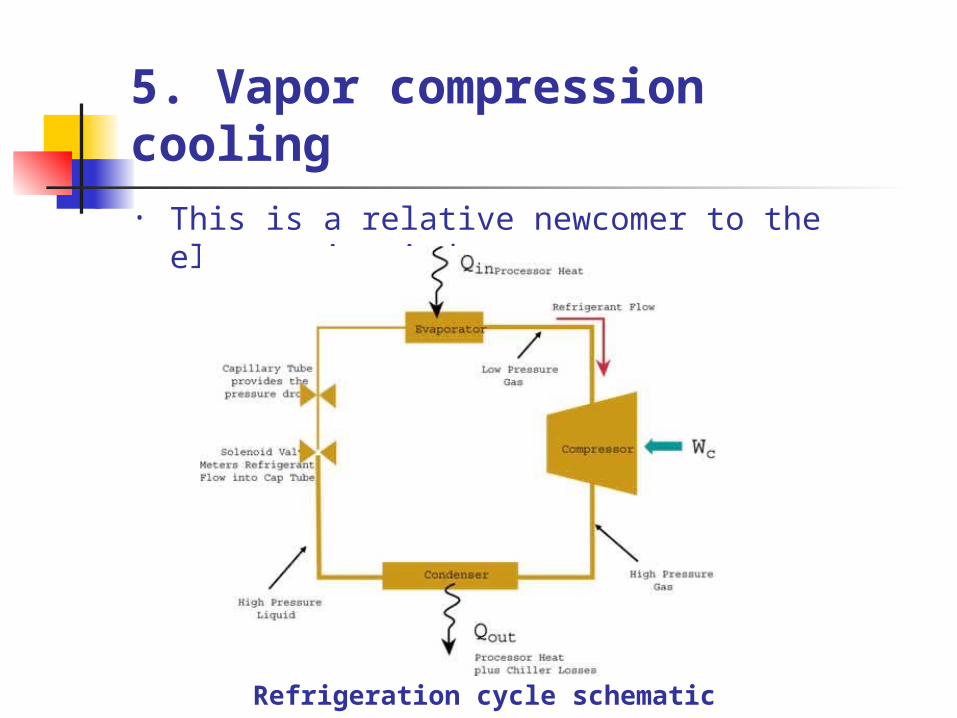
5. Vapor compression cooling • This is a relative newcomer to the electronics
industry.
Refrigeration cycle schematic
Applications
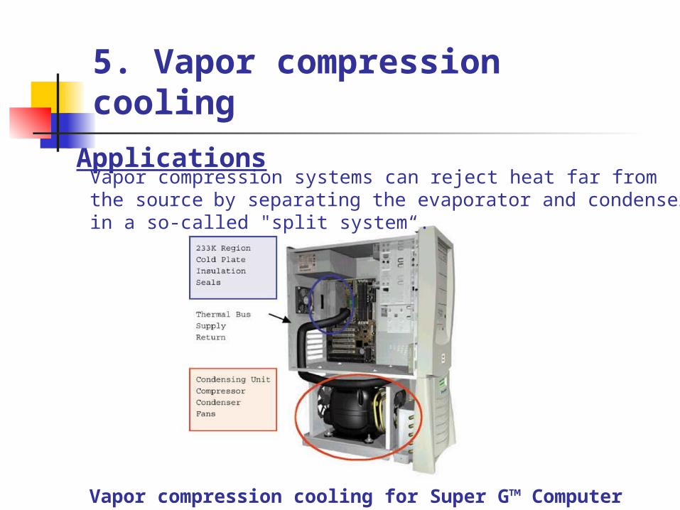
5. Vapor compression cooling
Vapor compression cooling for Super G™ Computer
Vapor compression systems can reject heat far from the source by separating the evaporator and condenser in a so-called "split system“.
5. Vapor compression cooling
Advantages:• Vapor compression can lift large heat
loads.• low mass flow rate.• high COP.• ability to transport heat away from its