This manual is the property of the owner, and is required for future maintenance. Please leave it with the owner when the job is complete. “UL CLASSIFIED (see complete marking on product)” “UL CLASSIFIED to Canadian safety standards (see complete marking on product)” UL Standard 555 (Listing #R13317) RECEIVING AND HANDLING Upon receiving dampers, check for both obvious and hidden damage. If damage is found, record all necessary information on the bill of lading and file a claim with the final carrier. Check to be sure that all parts of the shipment, including accessories, are accounted for. Dampers must be kept dry and clean. Indoor storage and protection from dirt, dust and the weather is highly recommended. Do not store at temperatures in excess of 100°F. Part Number 453946 INSTALLATION SUPPLEMENTS Refer to the appropriate Greenheck installation supplements for special requirements: • Support Mullions • Shaftwall Supplement • Drywall Supplement • Grille Installation Supplement • Drive Slip Supplement • Sealant Supplement • Sleeve Extension Supplement • Single sinde Retaining Angles Supplement Note: Refer to Greenheck IOM, Part #461335, for CFSD models to be installed in corridor ceiling applications. FD & DFD 150X MODELS 1 1 ⁄2 Hour Curtain Fire Dampers Vertical or Horizontal Mount FD and DFD 150X Series models are intended for installation in accordance with fire damper requirements established by: National Fire Protection Association NFPA Standard 80, 90A, & 101 IBC International Building Codes CSFM California State Fire Marshal Fire Damper Listing (#3225-0981:102) New York City (BSA/MEA listing #260-91-M) Installation, Operation and Maintenance Instructions Due to continuing research, Greenheck reserves the right to change specifications without notice. SAFETY WARNING: Improper installation, adjustment, alteration, service or maintenance can cause property damage, injury or death. Read the installation, operating, and maintenance instructions thoroughly before installing or servicing this equipment. WARRANTY Greenheck warrants this equipment to be free from defects in material and workmanship for a period of one year from the purchase date. Any units or parts which prove to be defective during the warranty period will be repaired or replaced at our option. Greenheck shall not be liable for damages resulting from misapplication or misuse of its products. Greenheck will not be responsible for any installation or removal costs. Greenheck will not be responsible for any service work or backcharges without prior written authorization.
Transcript
This manual is the property of the owner, and is required for future maintenance. Please leave it with the owner when the job is complete.
“UL CLASSIFIED (see complete marking on product)”“UL CLASSIFIED to Canadian safety standards (see complete marking on product)” UL Standard 555 (Listing #R13317)
RECEIvIng AnD HAnDLIngUpon receiving dampers, check for both obvious and hidden damage. If damage is found, record all necessary information on the bill of lading and file a claim with the final carrier. Check to be sure that all parts of the shipment, including accessories, are accounted for.
Dampers must be kept dry and clean. Indoor storage and protection from dirt, dust and the weather is highly recommended. Do not store at temperatures in excess of 100°F.
Part number 453946
InStALLAtIon SUPPLEmEntSRefer to the appropriate Greenheck installation supplements for special requirements:• SupportMullions• ShaftwallSupplement• DrywallSupplement• GrilleInstallationSupplement• DriveSlipSupplement• SealantSupplement• SleeveExtensionSupplement• SinglesindeRetainingAnglesSupplementNote: RefertoGreenheckIOM,Part#461335,for
CFSD models to be installed in corridor ceiling applications.
FD & DFD 150X moDELS1 1⁄2 Hour
Curtain Fire Dampersvertical or Horizontal mount
FD and DFD 150X Series models are intended for installation in accordance with fire damper requirements established by: national Fire Protection AssociationNFPAStandard80,90A,&101 IBC International Building Codes CSFm California State Fire marshalFireDamperListing(#3225-0981:102) new York City (BSA/MEAlisting#260-91-M)
Installation, Operation and Maintenance Instructions
Due to continuing research, Greenheck reserves the right to change specifications without notice.
SAFEtY WARnIng:Improper installation, adjustment, alteration, service or maintenance can cause property damage, injury or death. Read the installation, operating, and maintenance instructions thoroughly before installing or servicing this equipment.
WARRAntYGreenheck warrants this equipment to be free from defects in material and workmanship for a period of one yearfromthepurchasedate.Anyunitsorpartswhichprove to be defective during the warranty period will be repaired or replaced at our option. Greenheck shall not be liable for damages resulting from misapplication or misuse of its products. Greenheck will not be responsible for any installation or removal costs. Greenheck will not be responsible for any service work or backcharges without prior written authorization.
Pre-Installation guidelinesThe basic intent of a proper installation is to secure the fire damper in, not to, the opening in such a manner as to prevent distortion and disruption of damper operation. This is accomplished by allowing the fire damper in rated separation openings to expand and for the connecting duct to separate in the event of the collapse of the hanging system. The following items will aid in completing the damper installation in a timely and effective manner.
1. Check the schedules for proper damper locations within the building. Visually inspect the damper for damage and verify that the fusible link is in place or has not separated. If fusible link is not present or has separated, replace link. Never install a fire damper without the proper UL approved fusible link in place. (Fusible link is standard controloption.Anelectriclinkmayhavebeenprovided.)
2. Lift or handle damper using sleeve or frame.3. Install damper accordingly to comply with manufacturer’s appropriate UL procedure file number.
4. Dampermustbeinstalledintoductoropeningsquareandfreeoftwistorothermisalignment.Dampermustnotbesqueezed or stretched into duct or opening.
5. Damper must be kept clean and protected from dirt, dust and other foreign materials prior to and after installation. Examplesofsuchforeignmaterialsinclude,butarenotlimitedto:
a. Mortardustb. Drywall dustc. Firesafing materialsd. Wall texturee. Paint overspray
6. Dampershouldbesufficientlycoveredastopreventoversprayofspray-oninsulating,walltexturing,orspraypaintingwhenperformedwithin5feetofthedamper.Excessivedirtorforeignmaterialdepositscancausedamperto bind and not operate properly.
7. Caulking is not necessary, nor is it allowed, between the damper sleeve and the wall or floor opening (annular space). However, caulking may be applied to the retaining angles.
8. ACCESS:Suitableaccess(suchthatfusiblelinkscanbechanged)mustbeprovidedfordamperinspectionandservicing. Where it is not possible to achieve sufficient size access, it will be necessary to install a removable sectionofduct.(RefertoNFPA90A).
9. TheCodeAuthorityHavingJurisdiction(AHJ)mustevaluateandprovideapprovaloffinalinstallationwherevariations to these instructions are necessary.
These instructions apply to 11/2 hour rated fire dampers mounted in masonry, block or stud walls and concrete floors. Specific requirements in these instructions are mandatory. These instructions meet the requirements of UL 555. Installation shall complywiththerequirementsofNFPA90AStandardfortheInstallationofAirConditioningandVentilatingSystems.U.L.listingR13317,CaliforniaStateFireMarshallistings3225-981:102,andNewYorkCityBSA/MEAlisting260-91-Mastheyapply to these dampers.
note: Fire dampers are manufactured and labelled for either vertical or horizontal installation. The dampers must be installed in accordance with the labelling.
1. no ADDItIonAL SLEEvES ARE REQUIRED The fire damper extended frame is an approved sleeve
and can be properly installed without the need for a supplemental field installed sleeve. Damper frame shall extendamaximumof6in.(152mm)beyondthewallorfloor opening on each side.
Installation - Failure to follow these instructions will void all warranties.
2. CLEARAnCES REQUIRED BEtWEEn FIRE DAmPER SLEEvES AnD WALL/FLooR oPEnIngS
Fire damper assemblies expand during periods of intense heat. Therefore, it is essential that openings in walls or floors be larger than the fire damper assembly toallowforthisexpansion.Minimumclearancesrequired between the outside of fire damper sleeve assemblies and wall/floor openings are:
Figure 1: Retaining angle installation.3. SECURIng tHE FIRE DAmPER to WALL AnD
FLooR oPEnIngS Fire damper assemblies must be installed in wall and
floor openings using retaining angles on each side of the wall or floor as described below:
• Retaininganglesfor11/2 hour rated dampers with awidthandheight48in.(1219mm)orlessmustbea minimum of 20 ga. (1mm). Retaining angles for all 3 hour rated dampers and all dampers with a width orheightgreaterthan48in.(1219mm)mustbeaminimumof16gauge(1.5mm).Thelegoftheretainingangle on the damper sleeve shall be a minimum of 11/4 in. (32mm). The leg of the retaining angle on the wall/floorshallbelongenoughtocovertheannularspaceandoverlapthewall/floorbyaminimumof1in.(25mm).
• Retaininganglesmustbeattachedtothedamperusing one or more of the following methods of attachment:
(152mm) on center and a maximum of 2 in. (51mm) fromcorners.Theanglesmustbeattachedtoall4sidesofthesleevewithbuttjointsateachcorner.Aminimum of two attachments are required on each side, top and bottom. The angles need not be attached to each other at the corners.
•Retaininganglesshouldnotbefastenedtothewall/floor material. The angles should only sandwich the wall/floor and allow for damper expansion during periods of intense heat.
• Galvanizedsteelfiredampersandsleeves:1/8in.(3mm) per linear foot of damper width and height with aminimumclearanceof1/4in.(6mm).Recommended clearances,forwidthand/orheightdimensionsof:
less: 1 in. (25mm) clearance 3)Morethan96in.(2438mm):11/2in.(38mm)
clearance
These are total clearances (ignoring fastener heads) and do not need to be equally spaced around the damper. Refer to Section 3 and Figure 1 for additional installation considerations.
4. ConnECtIng DUCtS to tHE FIRE DAmPER AllductconnectionstoFD&DFD150Xseries
extended frame dampers must be “breakaway” type connections.Allconnectionsshownonpage5&6areconsidered breakaway. Factory furnished duct collars ontypesR& CR fire dampers are also considered breakaway(see Figure 2 & 3).
1/4 in. minimumtotal clearance
Wall or Floor
Maximum 6 in.
Maximum 6 in.
Duct
Duct
Duct
Damper
Damper
Damper
Wall or Floor
Wall or Floor
Retaining Angles (See Section 3)
Type A
Type B
On types R & CR factoryfurnished duct collarqualifies as breakaway connection.
Type C, CO, CR, & R
1/4 in. minimumtotal clearance
Wall or Floor
Maximum 6 in.
Maximum 6 in.
Duct
Duct
Duct
Damper
Damper
Damper
Wall or Floor
Wall or Floor
Retaining Angles (See Section 3)
Type A
Type B
On types R & CR factoryfurnished duct collarqualifies as breakaway connection.
Type C, CO, CR, & R
1/4 in. minimumtotal clearance
Wall or Floor
Maximum 6 in.
Maximum 6 in.
Duct
Duct
Duct
Damper
Damper
Damper
Wall or Floor
Wall or Floor
Retaining Angles (See Section 3)
Type A
Type B
On types R & CR factoryfurnished duct collarqualifies as breakaway connection.
Type C, CO, CR, & R
Figure 2: vertical mount type A, type B, and type C, Co, CR, R damper installation diagrams.
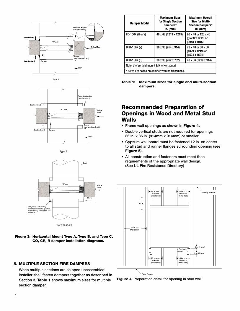
Recommended Preparation of openings in Wood and metal Stud Walls• FramewallopeningsasshowninFigure 4.
• Gypsumwallboardmustbefastened12in.oncenterto all stud and runner flanges surrounding opening (see Figure 5).
• Allconstructionandfastenersmustmeetthenrequirements of the appropriate wall design. (See UL Fire Resistance Directory)
Figure 4: Preparation detail for opening in stud wall.
table 1: maximum sizes for single and multi-section dampers.
4
Damper Model
Maximum Sizes for Single Section
Dampers* in. (mm)
Maximum Overall Size for Multi-
Section Dampers*in. (mm)
FD-150X (H or V) 48 x 48 (1219 x 1219) 96 x 48 or 120 x 40((2438 x 1219) or (3048 x 1016)
DFD-150X (V) 36 x 36 (914 x 914) 72 x 48 or 60 x 60(1829 x 1219) or(1524 x 1524)
DFD-150X (H) 30 x 30 (762 x 762) 48 x 36 (1219 x 914)
Note: V = Vertical mount & H = Horizontal
* Sizes are based on damper with no transitions.
5. mULtIPLE SECtIon FIRE DAmPERS
When multiple sections are shipped unassembled, installer shall fasten dampers together as described in Section 3. table 1 shows maximum sizes for multiple section damper.
Wall or Floor
Retaining Angles(See Section 4)
Sleeve (see sections 2 & 3)
Duct
“K” side
Damper
See Section 2
See Section 2
Type A
Wall or Floor
Retaining Angles(See Section 4)
Sleeve(see sections 2 & 3)
Duct
“K” side
Damper
See Section 2
See Section 2
Type B
Wall or floor
On types R & CR factory furnished duct collar qualifies as breakaway connection, see Section 5
Duct
Sleeve
Type C, CO, CR, & R
“K” side
Figure 3: Horizontal mount type A, type B, and type C, Co, CR, R damper installation diagrams.
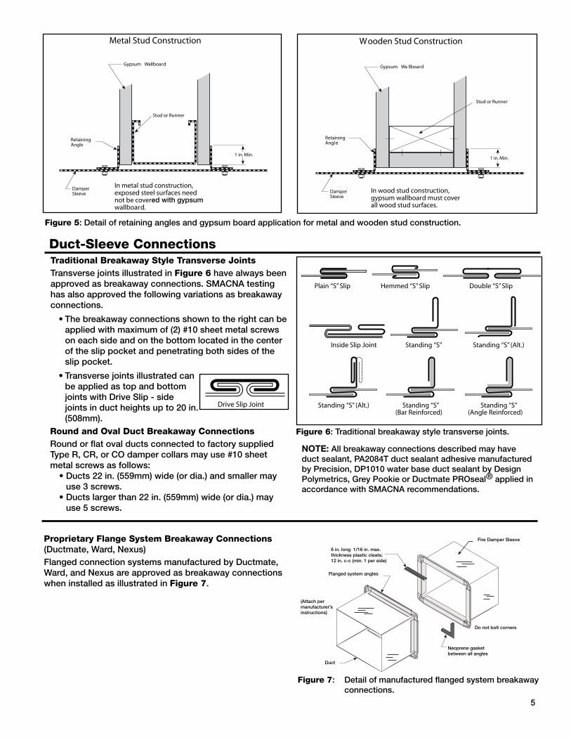
Duct-Sleeve Connectionstraditional Breakaway Style transverse JointsTransverse joints illustrated in Figure 6 have always been approvedasbreakawayconnections.SMACNAtestinghas also approved the following variations as breakaway connections.
•Thebreakawayconnectionsshowntotherightcanbeapplied with maximum of (2) #10 sheet metal screws on each side and on the bottom located in the center of the slip pocket and penetrating both sides of the slip pocket.
•Transversejointsillustratedcanbe applied as top and bottom joints with Drive Slip - side joints in duct heights up to 20 in. (508mm).
Round and oval Duct Breakaway ConnectionsRound or flat oval ducts connected to factory supplied Type R, CR, or CO damper collars may use #10 sheet metal screws as follows: •Ducts22in.(559mm)wide(ordia.)andsmallermay
use 3 screws. •Ductslargerthan22in.(559mm)wide(ordia.)may
use 5 screws.
Figure 6: Traditional breakaway style transverse joints.
NOTE: Allbreakawayconnectionsdescribedmayhaveductsealant,PA2084Tductsealantadhesivemanufacturedby Precision, DP1010 water base duct sealant by Design Polymetrics, Grey Pookie or Ductmate PROseal® applied in accordancewithSMACNArecommendations.
5
Figure 5: Detail of retaining angles and gypsum board application for metal and wooden stud construction.
Figure 7: Detail of manufactured flanged system breakaway connections.
Do not bolt corners
Fire Damper Sleeve
(Attachpermanufacturer’sinstructions)
Duct
Neoprene gasketbetween all angles
Flanged system angles
6in.long1/16in.max.thickness plastic cleats;12 in. c-c (min. 1 per side)
Proprietary Flange System Breakaway Connections (Ductmate, Ward, Nexus)Flanged connection systems manufactured by Ductmate, Ward, and Nexus are approved as breakaway connections when installed as illustrated in Figure 7.
These instructions apply to 11/2 hour rated fire dampers mounted in steel stud walls. Specific requirements in these instructions are mandatory. These instructions meet the requirements of UL555. Installation shall comply with the requirementsofNFPA90AStandardfortheInstallationofAirConditioningandVentilatingSystems.U.L.listingsR13317andR13743,CaliforniaStateFireMarshallistings3225-981:102and3225-1241:101,andNewYorkCityBSA/MEAlisting260-91-Mastheyapplytothesedampers.
Installation for Steel Stud Connection (SSC) option
6
1. no ADDItIonAL SLEEvES oR AngLES ARE REQUIRED
The fire damper extended frame is an approved sleeve and the Steel Stud Connection (SSC) Option allows fastening of the fire damper sleeve directly to the wall's steel stud framing. Damper frame shall extend amaximumof6in.(152mm)beyondthewallopeningoneitherside.MaximumsizefiredamperthatmaybeinstalledusingthisSSCoptionis36in.Wx36in.H(914mmx914mm).
2. InStALLAtIon Fire damper with SSC option must be in place before
the wall is constructed or it can be installed as the wall is being constructed. Wall opening is framed around the fire damper before sheet rock or other wall board material is applied to the steel studs. This installation provides appropriate protection for duct penetrations in fire resistant wall construction using steel studs with a fire resistance rating less than 3 hours. The following wall design numbers (as detailed in the UL Fire Resistance Directory) are appropriate for fire damper installations using this SSC option:
3. FRAmIng oF WALL oPEnIng Formawallopening1/8in.(3mm)to1/4in.(6mm)
larger than the OD of the fire damper's extended frame (sleeve) using the same metal studs and techniques required by the wall design per the UL Fire Resistance Directory. Open side of the steel stud channels shall face the fire damper and encompass the damper's retaining bar.
4. APPLY WALLBoARD AFtER DAmPER InStALLAtIon
Afterdamperisinstalled,wallboardshallbeappliedto steel stud framework in the manner required by the wall design per the UL Fire Resistance Directory listing.Aroundthedamperperimeteruseaminimumof 2 connections per side, spaced 12 in. (305mm) maximum and located a maximum of 2 in. (51mm) from each corner. No additional retaining angles are required to complete the installation.
5. ConnECtIng DUCtS to tHE FIRE DAmPER AllductconnectionstoFD&DFD150Xseries
extended frame dampers must be “breakaway” type connections.Allconnectionsshownonpage5&6areconsidered breakaway. Factory furnished duct collars ontypesR,CR,&COfiredampersarealsoconsideredbreakaway.
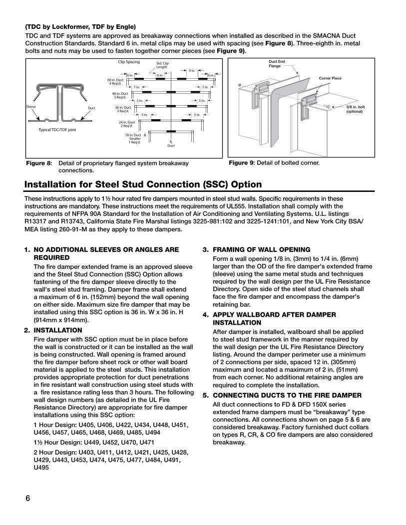
(tDC by Lockformer, tDF by Engle)TDCandTDFsystemsareapprovedasbreakawayconnectionswheninstalledasdescribedintheSMACNADuctConstructionStandards.Standard6in.metalclipsmaybeusedwithspacing(seeFigure 8). Three-eighth in. metal bolts and nuts may be used to fasten together corner pieces (see Figure 9).
Figure 8: Detail of proprietary flanged system breakaway connections.
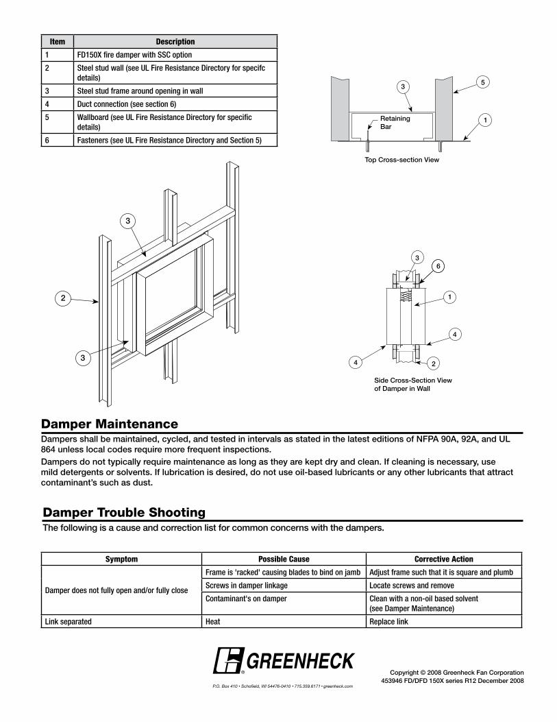
Damper maintenanceDampersshallbemaintained,cycled,andtestedinintervalsasstatedinthelatesteditionsofNFPA90A,92A,andUL864unlesslocalcodesrequiremorefrequentinspections.Dampers do not typically require maintenance as long as they are kept dry and clean. If cleaning is necessary, use mild detergents or solvents. If lubrication is desired, do not use oil-based lubricants or any other lubricants that attract contaminant’s such as dust.
Damper trouble ShootingThe following is a cause and correction list for common concerns with the dampers.
Item Description
1 FD150X fire damper with SSC option
2 Steel stud wall (see UL Fire Resistance Directory for specifc details)
3 Steel stud frame around opening in wall
4 Duct connection (see section 6)
5 Wallboard (see UL Fire Resistance Directory for specific details)
6 Fasteners (see UL Fire Resistance Directory and Section 5)
Symptom Possible Cause Corrective Action
Damper does not fully open and/or fully close
Frame is 'racked' causing blades to bind on jamb Adjust frame such that it is square and plumb
Screws in damper linkage Locate screws and remove
Contaminant's on damper Clean with a non-oil based solvent (see Damper Maintenance)