Passive thermal management for PEM fuel cell stack under cold weather condition using phase change materials (PCM) Agus P. Sasmito a, * , Tariq Shamim a , Arun S. Mujumdar b a Mechanical Engineering, Masdar Institute of Science and Technology, Abu Dhabi, P.O. Box 54224, United Arab Emirates b Department of Mechanical Engineering, National University of Singapore, 9 Engineering Drive 1, Singapore 117576, Singapore highlights An innovative concept of the passive thermal management using PCM and insulator for fuel cell in cold climates. The stack temperature can be kept above freezing for around two days. Several design factors are investigated with regard to the thermal management. The proposed concept can alleviate stack from performance degradation, long term durability and cold start-up issues. The result shows potential application for the automotive fuel cell operation in cold climates. article info Article history: Received 9 December 2012 Accepted 28 April 2013 Available online 9 May 2013 Keywords: Cold weather Freezeethaw cycle Phase change materials Polymer electrolyte fuel cell Thermal management abstract In cold weather conditions, i.e. winter, the polymer electrolyte membrane (PEM) fuel cell stacks typically undergo freezeethaw cycle operations which leads to performance degradation, long term durability, and start-up issues. In this study, we propose an innovative passive thermal management strategy to alleviate stack from freezeethaw cycles by utilizing phase change materials (PCM) and insulator to maintain the stack temperature above its freezing point. The impact of the passive thermal management of PCM is studied via mathematical model of the transient two-dimensional two-phase flow of solid eliquid PCM, insulator and PEM fuel cell stack comprising 20 cells, and associated conservation of mass, momentum and energy. The effect of key design and operating parameters are evaluated with regards to stack temperature. The model results indicate that the stack temperature can be maintained well above freezing temperature for around two days which shows potential for PEM fuel cell application, especially in automotive area. The results provide useful design guidelines for passive thermal management in PEM fuel cell stacks under cold weather conditions. Ó 2013 Elsevier Ltd. All rights reserved. 1. Introduction The operation of polymer electrolyte membrane (PEM) fuel cell stacks under cold weather (sub-freezing) condition requires careful considerations especially for the thermal and water management. As the temperature goes to subfreezing, the residual water con- tained within the cell can freeze which leads to performance degradation, long term durability, and start-up issues of the fuel cell [1e4]. The frozen water can cause mechanical damage in the fuel cell components and even severe physical breakdown, i.e. cracks due to thermally induced mechanical stresses. Cracks in the membrane lead to fuel and/or oxidant crossover which may trigger the uncontrolled reaction between hydrogen and oxygen with subsequent pinhole formation to membrane damage [5]. The re- petitive water phase changes from vapor to liquid to ice during shutdown and vice-versa during the start-up lead to volume expansion and shrinkage of about 9% [6]. This can cause delami- nation in the catalyst layer from both membrane and gas diffusion layer, which may result improper contact of functional layers and the loss of thermal and electrical interfacial contact [5e7]. Using a one-dimensional model, He and Mench [8] showed that the thicker the membrane and the higher the initial water content, the thicker is the developing ice layer, which is found to develop under the channel. They concluded that the best material for mitigating freeze-damage is a crack free virgin catalyst on a very thin rein- forced membrane, protected by a stiff gas diffusion layer [9]. Recently, Mishler et al. [10] showed through neutron radiography that the ice thickness peak exists in the cathode side of the mem- brane electrode assembly. * Corresponding author. Tel.: þ971 2 810 9320. E-mail address: [email protected](A.P. Sasmito). Contents lists available at SciVerse ScienceDirect Applied Thermal Engineering journal homepage: www.elsevier.com/locate/apthermeng 1359-4311/$ e see front matter Ó 2013 Elsevier Ltd. All rights reserved. http://dx.doi.org/10.1016/j.applthermaleng.2013.04.064 Applied Thermal Engineering 58 (2013) 615e625
Passive thermal management for PEM fuel cell stack under coldweather condition using phase change materials (PCM)
Agus P. Sasmito a,*, Tariq Shamim a, Arun S. Mujumdar b
aMechanical Engineering, Masdar Institute of Science and Technology, Abu Dhabi, P.O. Box 54224, United Arab EmiratesbDepartment of Mechanical Engineering, National University of Singapore, 9 Engineering Drive 1, Singapore 117576, Singapore
h i g h l i g h t s
� An innovative concept of the passive thermal management using PCM and insulator for fuel cell in cold climates.� The stack temperature can be kept above freezing for around two days.� Several design factors are investigated with regard to the thermal management.� The proposed concept can alleviate stack from performance degradation, long term durability and cold start-up issues.� The result shows potential application for the automotive fuel cell operation in cold climates.
a r t i c l e i n f o
Article history:Received 9 December 2012Accepted 28 April 2013Available online 9 May 2013
1359-4311/$ e see front matter � 2013 Elsevier Ltd.http://dx.doi.org/10.1016/j.applthermaleng.2013.04.06
a b s t r a c t
In cold weather conditions, i.e. winter, the polymer electrolyte membrane (PEM) fuel cell stacks typicallyundergo freezeethaw cycle operations which leads to performance degradation, long term durability,and start-up issues. In this study, we propose an innovative passive thermal management strategy toalleviate stack from freezeethaw cycles by utilizing phase change materials (PCM) and insulator tomaintain the stack temperature above its freezing point. The impact of the passive thermal managementof PCM is studied via mathematical model of the transient two-dimensional two-phase flow of solideliquid PCM, insulator and PEM fuel cell stack comprising 20 cells, and associated conservation of mass,momentum and energy. The effect of key design and operating parameters are evaluated with regards tostack temperature. The model results indicate that the stack temperature can be maintained well abovefreezing temperature for around two days which shows potential for PEM fuel cell application, especiallyin automotive area. The results provide useful design guidelines for passive thermal management in PEMfuel cell stacks under cold weather conditions.
� 2013 Elsevier Ltd. All rights reserved.
1. Introduction
The operation of polymer electrolyte membrane (PEM) fuel cellstacks under cold weather (sub-freezing) condition requires carefulconsiderations especially for the thermal and water management.As the temperature goes to subfreezing, the residual water con-tained within the cell can freeze which leads to performancedegradation, long term durability, and start-up issues of the fuelcell [1e4]. The frozen water can cause mechanical damage in thefuel cell components and even severe physical breakdown, i.e.cracks due to thermally induced mechanical stresses. Cracks in themembrane lead to fuel and/or oxidant crossover which may triggerthe uncontrolled reaction between hydrogen and oxygen with
to).
All rights reserved.4
subsequent pinhole formation to membrane damage [5]. The re-petitive water phase changes from vapor to liquid to ice duringshutdown and vice-versa during the start-up lead to volumeexpansion and shrinkage of about 9% [6]. This can cause delami-nation in the catalyst layer from both membrane and gas diffusionlayer, which may result improper contact of functional layers andthe loss of thermal and electrical interfacial contact [5e7]. Using aone-dimensional model, He andMench [8] showed that the thickerthe membrane and the higher the initial water content, the thickeris the developing ice layer, which is found to develop under thechannel. They concluded that the best material for mitigatingfreeze-damage is a crack free virgin catalyst on a very thin rein-forced membrane, protected by a stiff gas diffusion layer [9].Recently, Mishler et al. [10] showed through neutron radiographythat the ice thickness peak exists in the cathode side of the mem-brane electrode assembly.
Subfreezing operation of PEM fuel cell also causes performancedegradation. Mukundan et al. [11] showed that the operatingvoltage of fuel cell drops from 0.6 V to 0.5 V after 9 freezeethawcycles at constant current density of 10,000 A m�2 under fullyhumidified reactant, and completely failed after 10 cycles due tophysical damage of gas diffusion layer and membrane. They alsoshowed that fast cooling (quenching) can expedite the performancedegradation under freezeethaw cycles [12]. Cho et al. [6] experi-mentally measured the current density of PEM fuel cell operatingunder cyclic freezeethaw from 80 to �10 �C; and found that afterfour cycles, the current density dropped from 8800 to 7800 A m�2
at constant cell voltage of 0.6 V. They also reported that the cathodeelectrochemical surface area (measured by cyclic voltammetry)dropped by 25% during these cycles along with the increase ofmembrane resistance. On the other hand, Oszcipok et al. [13]showed a 5.4% performance loss for each freezeethaw cycle. Limet al. [14] compared three different gas diffusion layer materials,i.e., felt, cloth and paper, which had similar basic properties, e.g.,porosity, electrical resistance and hydrophobicity, but differed inthickness and bending stiffness subject to freezeethaw cycle. Theresults showed that felt GDL had the lowest performance degra-dation over cycles followed by cloth and paper GDLs. The amount ofwater residing inside the cell after shutdown was found to be animportant factor for the durability and performance degradation,Alink et al. [15] found that the stack showed little degradationwhen it was dried out before cooling down to subfreezing conditionwhereas freezing in high amount of water inside the stack resultedin performance degradation which was mainly attributed to thechanges in wetting properties. Using synchrotron X-ray basedmicro-computed tomography (mCT) to investigate porosity changeof gas diffusion layer under freezeethaw cycles, Kim and Lee [16]found cyclic variation of porosity change and observed severalcracks at the interface between gas diffusion layer andmicroporouslayer.
Another concern at subfreezing operation of PEM fuel cell is thestart-up; the contained water inside the cell, which is in the form ofice film, blocks the reactant to reach catalyst layer resulting in failedcold startup [10]. Thus, it has been suggested to remove watercontent inside the cell before shutdown through gas purging pro-cedure [9,12,13,15,17e20]. This procedure has beenwidely acceptedas an incontrovertible precondition for the successful cold start[15,21,22]. Another procedure for the prevention of water freezinginside the cell is the use of anti-freezing solutions such as alcohol toflood the cell before freezing [23] or filling the small pores of gasdiffusion layer with inert liquid [24]. During cold startup, temper-ature control is another important factor; the stack temperaturehas to be maintained above zero to avoid water freezing whichcould results in failed startup [25]. The operating current densityalso needs to be limited so as to control water generation and iceformation which may cause failed startup [26]. Oszcipok [25] rec-ommended an active support to heat up the stack to above freezingpoint during the start-up. Similarly, Sundaresan and Moore [27,28]suggested to use external heating to expedite the start-up timesince the self heating from heat generated by electrochemical re-action is not sufficient to quicklywarm up the cell. Khandelwal et al.[29] showed through mathematical model that the time requiredfor successful cold startup is 69 s at 10,000 A m�2 by consideringthe heat generation from fuel cell reaction only, without the pres-ence of external heater and initial ice. However, at much lowercurrent density of 1000 A m�2, the heat generated from electro-chemical reaction itself is not sufficient to bring the stack temper-ature up from �20 to 0 �C which may cause failed start-up.
Pesaran et al. [5] summarized various mitigation strategies forthe cold start-up into two categories: “thaw-heating at startmethod” and “keep-warm method”. The former method is widely
adopted by many researchers as explained in previous paragraphs.It requires supporting technologies including water drainage (gaspurging) during shutdown, rehumidification at the start-up, icemanagement in the system components and functional layers, anddesign of the thawing/heating power sources. Many strategies havebeen proposed to heat up the stack during the cold start-up such ascatalytic combusting hydrogen in flow channels [30], wire heatingusing batteries [31,32], coolant heating [19] and hot air blowing[33]. These strategies, however, require additional power source/parasitic loads depending on the amount of water ice inside thestack that need to be melted and the initial stack temperature.Other drawback of this method is the possible physical damagesand cracks of functional layers due to freezeethaw cycle. The lattermethod, on the other hand, basically maintains the stack temper-ature at above zero degree and water is not allowed to freeze.Hence, neither gas purging during shutdown nor stack heat upduring startup is required. The start-up process is similar to normalstart-up; and the possible physical damages and cracks of variousfunctional layers due to freezeethaw cycle are eliminated. Thismethod includes adding thermal insulation in the stack [34] andadding active heat source to the stack for which the heat can besupplied either continuously or intermittently from batteries, cat-alytic reaction or combustion etc. This, however, would requireextensive amount of energy, especially if the stack is stored for along time. Pesaran et al. [5] observed through 1D thermal modelthat the stack temperature can bemaintained above zero degree forabout two days by adding 4 inch thick thermal insulation materialto the stack. However, this increases the size of the stack signifi-cantly which makes this strategy impractical for automotive ap-plications. In addition, both mitigation methods are found to addcomplexities and require additional auxiliary equipment which inturn increase the cost of the system. The US Department of Energy(DoE) has set a target for cold start-up of fuel cell to reach 50% ratedpower in 30 s starting from �20 �C with the maximum startup/shutdown energy of 5 MJ (1.39 kWh) and 5000 h durability underfreezeethaw cycle conditions [4,35]. Currently, the required timefor cold start-up of 30 s has already been achieved by many re-searchers [13,15,25,28,29]. However, the requirement formaximum energy is still difficult to meet as the start-up procedurerequires high amount of energy. There is, thus, a need for newtechnology/procedure/method/design which is able to meet thetarget set by the US DoE, i.e., fast start-up, low parasitic loads andhigh durability.
In recent years, phase change material (PCM), such as paraffinwax, has received significant attention due to its high latent heat ofmelting and solidification and potential for various applications,ranging from electronic cooling [36,37], thermal energy storage[38e40], thermal management in building [41,42], suspended incoolant fluid as micro-encapsulated phase change material(MEPCM) slurry for heat exchanger [43e45], battery cooling [46,47]to name but a few. Reviews of diverse applications of PCM are alsoavailable [48e50]. Sabah et al. [46] compared the effectiveness ofpassive cooling by PCM with that of active (forced air) cooling forthermal management in batteries. They concluded that the passivecooling was able to meet the operating range requirements moreeffectively, without the need for additional external pumpingpower.
To contribute to the solution of thermal management strategiesfor fuel cell utilization in cold climates, we introduce new appli-cation of PCM for passive thermal management. An innovativedesign concept of “keep-warm method” utilizing combination ofthermal insulator and phase change material as a passive heatsource is proposed. This is expected to reduce the insulator thick-ness significantly and eliminate the external/active heating equip-ment which would reduce the complexity and the cost of the
system. Thus, it would enable fuel cell for rapid start-up undernormal procedure (above 0 �C) and avoid physical damage offunctional layers due to freezeethaw cycles. The main advantage ofthis concept is that the PCM does not require any external energyfor charging as it can utilize the waste heat generated by fuel cellelectrochemical reaction to be stored as latent heat; and, to someextent, it reduces the cooling load requirement during the charging(melting). Here, the validated PCM model developed previously[37e40,51] is extended and implemented in the fuel cell stack so asto provide a heat source together with a thermal insulator to reducethe heat loss to ambient. Within this framework, a study is carriedout to evaluate how key factors e PCM thickness, type of PCMs,insulator thickness and ambient conditions e affect the stacktemperature.
The layout of the paper is as follows. First, the mathematicalformulation is introduced, followed by a brief discussion of itsimplementation with a one-domain approach. The questionwhether the proposed method is able to meet the criteria targetedby the DoE is addressed. Parametric studies of several key designand operating parameters are then carried out with regards to thethermal management, followed by the investigation of the effect ofadditional PCM to the thermal management of fuel cell duringoperation. Finally, conclusions are drawn with the emphasis onhow the presented concept can aid engineer tomeet the DoE target.The extension of the work is also highlighted especially on thepractical implementation and the design optimization.
2. Model development
The two-dimensional mathematical model (see Fig. 1a) com-prises three component, viz., PEM fuel cell stacks, PCM thermalstorage and thermal insulator, to allow for a conjugate heat transferbetween stack, PCM, insulator and ambient, which is modeled asnatural convection boundary condition. The simulation is started asthe stack shuts down. The heat from the stack is transferred to theambient by conduction and convection (at the molten state) in thePCM and by conduction in the insulator. The PCM acts as a passiveheat source by supplying heat from the latent heat of phase changeto keep the stack warm, whereas the insulator adds thermalresistance to the heat conduction so that the heat loss to theambient is minimized. Furthermore, the start-up condition is alsosimulated in order to elucidate the effect of additional PCM to thethermal management during the stack operation. To save thecomputational cost, the three-dimensional physical model is
Fig. 1. Schematic representation of passive thermal management of fuel cell in cold climateand (b) Single cell inside the stack.
reduced into two-dimensional counterpart without sacrificingessential physics of the phenomena due to negligible flux variationin the spanwise direction (z). Since this work only relates to laminarflow, a precise numerical solution is adequate to simulate realityvery closely.
2.1. Fuel cell stack
The PEM fuel cell stack comprises 20 cells stacked up in serieswith each cell consists of a membrane (m) sandwiched by twocatalyst layer (cl), two gas diffusion layer (gdl), and two bipolarplates (bp) which is micro-machined to form flow channels; seeFig. 1b for details. Here, the main mode of heat transfer inside thefuel cell is assumed to be governed by conduction, no convectiveheat transfer inside the stack is assumed since there is no gas flowat the anode and cathode flow channel during the shutdown pro-cess. The conservation of energy is given by transient heat con-duction equation
v
vt
�rfc;icp;fc;iT
�¼ V$
�kfc;iVT
�þ Stemp: (1)
In the above equations, t denotes time, rfc,i is the fuel cell densitywhich varies according to each functional layer, cp,fc,i is the specificheat of the fuel cell depending on the functional layers and kfc,i isthermal conductivity of the fuel cell for each layer. Stemp is the heatsource in the fuel cell which is deactivated (Stemp ¼ 0) after thestack shutdown (Section 4.1e4.6) and is activated (Stemp> 0) duringthe stack start-up simulation (Section 4.7). The material propertiesof each functional layer are listed in Table 1.
2.2. Phase change material (PCM)
In the PCM thermal storage, fluid flow, heat transfer and phasechange processes of PCM are taken into consideration. The PCM ismodeled as single phase fluid. The melting and/or solidification ismodeled using an enthalpyeporosity technique [37e39,51]. Here,the melt interface is not tracked explicitly, instead, it employs theliquid fraction of the cell volume. The enthalpy of the PCM iscomputed as the sum of sensible heat and latent heat of fusion.Furthermore, the PCM thermophysical properties are treated asfunctions of temperature. For first approximation, we assume thatthe gravitational effect is negligible and the natural convection ismainly govern by the temperature difference which is captured inthe viscosity and the PCM density as function of temperature.
condition using combination of PCM and thermal insulator: (a) Computational domain
0 0.05 0.1 0.15-20
-10
0
10
20
30
40
50
60
T( °
)C
Lstack
(m)
t = 45 h
t increasing
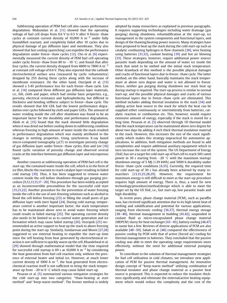
Fig. 3. Local temperature distribution at the middle of the stack (x ¼ 6.25 cm) atvarious evolution time: 0, 5, 10, 15, 20, 25, 30, 35, 40, 45, 50, and 55 h.
Table 1Base-case geometry, physical and operating parameters.
Furthermore, during stack storage, the solidification process ismainly govern by conduction [40]. For clarification, in a 20mmPCMthickness, Rayleigh number, Ra ¼ gbDTt3h=ðayÞ; is expected to be inthe order of 105e107 Here, g is the magnitude of the gravitationalacceleration; b is the thermal expansion coefficient of liquid PCM;DT is the representative temperature difference; this the PCMthickness; y and a are the kinematic viscosity and the thermaldiffusivity of the liquid PCM, respectively. Since Ra is relativelymuch smaller than Ra < 109, the effect of natural convection in themolten PCM is expected to be negligible. To confirm this approxi-mation, we conduct a test case by comparing evolution of stacktemperature from models with and without gravitational effect.The results are depicted in Fig. 3 (see black solid and grey dottedlines). It shows that temperature difference from the model withand without gravitational effect is only differs by around 2%. Thisimplies that the natural convection effect due to gravitational forceis negligible. Thus, the conservation equations of mass, momentumand energy are given by [37e39]
0 10 20 30 40 50 60-20
-10
0
10
20
30
40
50
60
Teva
(°)
C
t (h)
with PCM, with insulator,gravity ONwith PCM, with insulator,gravity OFFno PCM, no insulatorwith PCM, no insulatorno PCM, with insulator
Fig. 2. Stack temperature evolution for various designs: no PCM and no insulator ;no PCM with insulator ; with PCM and no insulator ; with PCM with insulatorand no gravity effect ; and with PCM with insulator and with gravity effect .
v
vt
�rpcm
�þ V$
�rpcmu
�¼ 0; (2)
v
vt
�rpcmu
�þ V$
�rpcmu5u
�¼ V$sþ Smom; (3)
v
vt
�rpcmHpcm
�þ V$
�rpcmuHpcm
�¼ V$
�kpcmVT
�: (4)
where s is the total stress tensor, rpcm is the PCM density, u is thePCM velocity, p is the pressure, mpcm is the dynamic viscosity of thePCM, kpcm is thermal conductivity of the PCM and Hpcm is theenthalpy of the PCM, defined as
Hpcm ¼ hpcm þ DHpcm; (5)
where hpcm is the sensible heat of the PCM, given by
hpcm ¼ hrefpcm þZT
Tref
cp;pcmdT ; (6)
where hrefpcm is the reference enthalpy and cp,pcm is the heat capacityof PCM. Furthermore, DHpcm is the enthalpy change due to solideliquid phase change, estimated by
DHpcm ¼ bLpcm; (7)
where Lpcmis the latent heat of fusion of the PCM and b is themelted mass fraction, defined as the mass ratio of the melted PCMto the total mass of the PCM. The PCM starts to melt at Tsolidius andcompletely melts at Tliquidius and the melted fraction can vary from0 to 1 at the temperature in between Tsolidius and Tliquidius.
where mpcm is the PCM viscosity. Furthermore, the enthalpyeporosity technique treats the mushy region (partially solidifiedregion) as a porous medium. The porosity in each cell is set equal tothe liquid fraction in that cell. In fully solidified regions, the porosityis equal to zero, which extinguishes the velocities in these regions.Themomentum sink due to the reduced porosity in themushy zoneis approximated by
Smom ¼ � ð1� bÞ2�b3 þ 0:001
�ℭu (10)
where ℭ is the mushy zone constant. The mushy zone constantmeasures the amplitude of the damping; the higher this value, thesteeper the transition of the PCM velocity to zero as it solidifies.Very large values, however, may cause the solution to oscillate.Thus, the value of 105 is used in this simulation based on the pre-vious work [37,52,53].
As mentioned earlier, thermophysical properties of the PCM arefunctions of temperature. The PCM material considered in thiswork is paraffin wax for the base-case; its density, rpcm, as a func-tion of temperature, is given by [37,52,53]
rpcm ¼ 7500:001ðT � 319:15Þ þ 1
; (11)
The PCM thermal conductivity, kpcm, is estimated by [37,52,53]
kpcm ¼ 0:21Wm�1K�1 if T<Tsolidiuskpcm ¼�0:045Tþ14:57175Wm�1K�1 if Tsolidius<T<Tliquidiuskpcm ¼ 0:12Wm�1K�1 if T>Tliquidius
:
(12)
The PCM viscosity is defined as [37,52,53]
mpcm ¼ 0:001exp��4:25þ 1790
T
�(13)
2.3. Thermal insulator
In the insulator, heat flows by the conduction mode from thePCM to the ambient. Here, the thermal conductivity of insulator isdesigned to be as low as possible to prevent heat loss to theambient. The material chosen in this study is polyurethane foamwith thermal conductivity of 0.036 W m�1 K�1 [5]. The conserva-tion of energy is represented by the transient heat conductionequation.
v
vt
�rinscp;insT
� ¼ V$ðkinsVTÞ (14)
2.4. Boundary and initial conditions
As the model implements single domain approach, the bound-ary conditions are only needed to be specified at the external sur-face of the domain, i.e., interface between the insulator and theambient. The internal boundary conditions in between each layer ofthe fuel cell are prescribed as coupled wall to allow for conjugateheat transfer.
The boundary conditions are prescribed as follows
� At the outer surface: we prescribe natural convection boundarycondition where the ambient is set to�20 �C for the base-case,defined as
�kinsvTvn
¼ hconvðTamb � TÞ (15)
� At the walls of PCM container: no slip conditions is prescribedfor flow; conjugate heat transfer is set between the PCM-fuelcell stack and the PCM-insulator
u ¼ 0; Tþ ¼ T�: (16)
The initial conditions are:
� Shut down:
t ¼ 0 T ¼ Top u ¼ 0 p ¼ p0 (17)
� Start up:
t ¼ 0 T ¼ T init u ¼ 0 p ¼ p0 (18)
3. Numerics
The computational domains (see Fig. 1a) were created in Auto-CAD 2010. The commercial pre-processor software GAMBIT 2.3.16was used for meshing, labeling boundary conditions and deter-mining the computational domain. After mesh independencestudy, the computational domainwas resolved with around 5�105
elements: a fine structured mesh near the wall to resolve theboundary layer and an increasingly coarser mesh in the middle ofthe PCM container in order to reduce the computational cost.
Equations 1e14 together with appropriate boundary conditionsand constitutive relations comprising of four dependent variableseu, v, p, and T e were solved using the finite volume solver Fluent6.3.26. The model is solved using one-domain approach for whichthere is no need to specify internal boundary condition to allow forconjugate heat transfer. User-defined functions (UDF) were writtenin C language to account for temperature-dependence of thethermophysical properties of the PCM.
The equations were solved with the well-known Semi-ImplicitPressure-Linked Equation (SIMPLE) algorithm, second-order up-wind discretization and Algebraic Multi-grid (AMG) method. As anindication of the computational cost, it is noted that on average,around 20 iterations per time step is required and w100 MB ofRandomAccess Memory (RAM) are needed for convergence criteriafor all relative residuals of 10�6; this takes around 30 h computationfor simulation time of 60 h with adaptive time step on a worksta-tion with dual six-core processor (2.66 GHz) and 12 GB of RAM.
4. Results and discussion
Simulations were carried out for typical condition found in PEMfuel cell stack operating under cold weather conditions. The ge-ometry, operating and physical parameters are summarized inTable 1. The PCM model was validated against experimental mea-surement for temperature and liquid fraction in previous works[37,51]. In the following, stack temperature with and without PCMwill be presented, afterwhich the effect of key design and operatingparameters are evaluated.
0 10 20 30 40 50 60-20
-10
0
10
20
30
40
50
60
Teva
(°)
C
t (h)
th,PCM
increasing
0 10 20 30 40 50 600
0.2
0.4
0.6
0.8
1
βeva
t (h)
th,P CM
5mm
th,P CM
10mm
th,P CM
20mm
th,P CM
40mm
th,PCM
increasing
a)
b)
Fig. 4. (a) Stack average temperature and (b) average liquid fraction evolution overtime for various PCM thickness: 0 ; 5 ; 10 ; 20 ; and 40 mm .
First, the simulations were carried out by comparing fourpossible designs: stack without any additional insulation, stackwith thermal insulator only, stack with PCM only, and our proposeddesign e stack with combination of PCM and thermal insulator.Earlier work by Pesaran et al. [5] showed that without any insu-lation, stack temperature goes down to zero degree in less than 5 h.This is indeed the case as can be inferred from Fig. 2 where fastcooling (quenching) occurs in the stack without any insulation. Thiswould adversely affect the durability, performance degradation andthe start-up as explained in the Introduction section. We furtherexamine the effect of additional thermal insulation to minimize theheat loss to the ambient. As expected, adding a 2 cm thicknessinsulator can assist in maintaining the temperature above zerodegree for slightly longer time (up to w10 h). Thicker insulation isexpected to extend the warm temperature longer; however, thiswould significantly increase the stack size which is impractical,especially for automotive application. Looking to the effect ofadditional PCM to stack for passive heat source, we note that byadding the PCM only, temperature can also be maintained abovezero degree for slightly longer (up to w10 h) similar to that withinsulator only. Now, our proposed design, i.e., combination of PCMand insulation, is evaluated with regards to stack temperature. Itcan be seen that the proposed design is superior among others:stack temperature is maintained above freezing for more than 40 hwhich shows potential for typical automotive application. Ascompared to the earlier design by Pesaran et al. [5], which showsabove freezing temperature can be maintained for w40 h withadditional 4 inch insulator thickness, our design only requires lessthan 2 inch thickness combination of PCM and insulator. This wouldsignificantly reduce the total stack size. A closer inspection revealsthat the heat released from the PCM during the phase change(solidification) is able to keep almost constant stack temperature atits solidification point (46e48 �C) for more than 15 h. Of course,longer duration of keeping warm stack temperature is possible toachieve, for example, by designing thicker thermal insulator and/oradding more PCM volume as will be discussed later.
Fig. 3 shows local temperature distribution at the middle of thestack from top to bottom. The stack temperature is uniformlydistributed from top to bottom. A steep temperature gradient is seenat the insulator and less stepper gradient is observed at the PCMlayer. This is attributed to the low thermal conductivity of the fuelcell functional layers, PCM and insulator. We note that slightly non-linear temperature distribution is observed at the PCM zone due tonatural convection heat transfer e especially when the PCM tem-perature is above melting temperature (molten state) e ascompared to other zones, i.e. stack and insulator forwhich they havevery linear temperature profile due to the conduction heat transfermode only. It is also observed that the local temperature decreasesover time as some of the thermal energy in the stack is transferred tothe ambient. It is noteworthy that stack temperature is onlydecreased slightly (w3 �C) during the solidification of the PCM.Looking at the two-dimensional geometrical effect to the temper-ature distribution, we note only slight temperature difference (lessthan 10%) between middle and the corner of the stack (not shownhere due to page limitation). This uniform stack temperature dis-tribution is beneficial to avoid non-uniform stress distributionwhich induces localized bending stress and delamination.
4.2. Effect of PCM thickness
One of the key factors that determines the heat storage capacityis the PCM thickness as it is directly associated with the total PCMvolume. Theoretically, the thicker the PCM layer, the higher the PCM
volume and the thermal storage capacity. Here, five different PCMthicknesses are considered: 0,0.5,1,2 and 4 cm, while the insulatorthickness is kept constant at 2 cm. As shown in Fig. 4a, increasingthe PCM thickness results in longer duration of above freezingcondition. We note that increasing the PCM thickness from two to4 cm results in increasing the above freezing temperature durationby almost two times (up to more than 60 h); whereas, reducing thePCM thickness from two to 1 cm decreases the above freezingduration by 50% (w30 h). This is mainly due to the thermal storagecapacity for whichmore PCM is solidified in thicker design and vice-versa, which is represented by solidification time in Fig. 4b. It is seenthat the PCM is able to supply passive heat for around 5,10,18 and37 h for the PCM thicknesses of 0.5,1,2 and 4 cm, respectively. This isdue to the heat release from the solidification represented by liquidfraction evolution (Fig. 4b) and is further mirrored by almost con-stant stack temperature at the PCM solidification point (Fig. 4a).Hence, it can be deduced that the PCM thickness has significanteffect to the above freezing temperature duration.
4.3. Effect of insulator thickness
Besides the PCM thickness, the insulator thickness also affectsthe above freezing temperature duration since it acts as a heatresistance to the ambient. In this particular case, we vary the
insulator thickness, i.e.,0, 0.5, 1, 2, and 4 cm, while keeping the PCMthickness constant. Fig. 5a shows that an increase in the insulatorthickness gives rise to a longer above freezing temperature dura-tion due to higher thermal resistance which, in turn, reduces theheat loss to the ambient. Increasing the insulator thickness fromtwo to 4 cm can double the above freezing temperature duration;while reducing the insulator thickness from two to 1 cm decreasethe above freezing duration by one-fourth. This is attributed to theheat release during the phase change which is represented byliquid fraction evolution from liquid (bave ¼ 1) to solid (bave ¼ 0) inFig. 5b. As the thermal resistance increased, the 2 cm thick PCM cansupply passive heat to the stack for longer duration: the solidifi-cation time increases from w5 to 10 to 18e30 h as the insulatorthickness is increased from 0.5 to1 to 2 and to 4 cm, respectively(Fig. 5b). Clearly, a careful balance has to be struck between thePCM thickness and the insulator thickness to ensure optimumabove freezing temperature duration whilst maintaining the min-imum size, weight and the cost of the system. An optimizationstudy on the design factors, which is beyond the scope of this paper,will be considered in future work.
4.4. Effect of PCM type
A further point of interest in this study is the PCM type as it hasdifferent thermophysical properties and is expected to have
0 10 20 30 40 50 60-20
-10
0
10
20
30
40
50
60
Teva
(°)
C
t (h)
th,insulator
increasing
0 10 20 30 40 50 600
0.2
0.4
0.6
0.8
1
βeva
t (h)
th,insulator
0mm
th,insulator
5mm
th,insulator
10mm
th,insulator
20mm
th,insulator
40mm
th,insulator
increasing
a)
b)
Fig. 5. (a) Stack average temperature and (b) average liquid fraction evolution over timefor various thermal insulator thickness: 0 ; 5 ; 10 ; 20 ; and 40 mm .
significant impact to the heat transfer characteristics. The perfor-mance of three different PCM materials, which are commerciallyavailable in the market e paraffin (base-case), n-eicosane andRubitherm27 (RT27, see Ref. [58] for details) e is evaluated withregards to heat transfer performance and above freezing duration.Note that the main difference of these three PCMs is the solidifi-cation temperature and the latent heat content (see Table 1 fordetails of the thermophysical properties) for each PCM. The stackaverage temperature over time as well as the liquid fraction evo-lution during the solidification are shown in Fig. 6. Here, severalfeatures are apparent; foremost among them is the difference insolidified temperature yields in different constant above freezingtemperature. It is noted that paraffin solidifies and keep the stack atconstant above freezing temperature of 46 �C, while n-eicosane isat 36 �C, and RT27 is at 26 �C. Looking closer to the constant abovefreezing temperatures, n-eicosane is able to maintain constantabove freezing temperature in the longest duration, followed byRT27 and paraffin. This is mainly attributed to the higher latent heatfor n-eicosane (247 kJ/kg) as compared to RT27 (179 kJ/kg) andparaffin (173.4 kJ/kg), which is mirrored by the liquid fractionevolution in Fig. 6b: the slope of liquid fraction evolution for n-eicosane is the steepest among others, followed by RT27 andparaffin. It reveals that n-eicosane is able to supply passive heat tothe system for w23 h, while RT-27 and paraffin provide the heatsource for w20 and w18 h, respectively.
0 10 20 30 40 50 60-20
-10
0
10
20
30
40
50
60
t (h)
Teva
(°)
C
ParaffinN-eicosaneRT27
0 10 20 30 40 50 600
0.2
0.4
0.6
0.8
1
t (h)
βeva
ParaffinN-eicosaneRT27
a)
b)
Fig. 6. (a) Stack average temperature and (b) average liquid fraction evolution overtime for three different PCM types: paraffin ; n-eicosane ; and RT27 .
A proper selection of the PCM type is important: ideally, thePCM must have higher latent heat of solidification to keep longerabove freezing duration as well as higher solidification temperature(close to fuel cell operating temperature, w50e80 �C) to speed-upthe start-up process and to reduce the component degradationfrom thermal cycles. In this particular case, paraffin yields thehighest solidification temperature (46 �C) which is close to fuel celloperating temperature (w50e80 �C); however, the latent heat offusion is the lowest among others, which is a disadvantage.Conversely, n-eicosane is found to have slightly lower solidificationtemperature (36 �C) which is farther from the fuel cell operatingtemperature; but it has higher latent heat to keep the abovefreezing temperature longer. The cost and availability would, mostlikely, decide the selection between these two PCMs. Furthermore,new type of the PCM which has high latent heat and high solidi-fication temperature (close to fuel cell operating temperature)needs to be developed in future for this particular application.
4.5. Effect of ambient temperature
During winter, ambient temperature can vary significantly fromzero degree to extreme subzero temperature and can affect the fuelcell operation/performance. To ascertain the impact of ambienttemperature, four different ambient temperatures, viz..�5, �10,�20 and �30 �C are examined. Fig. 7 depicts the stack temperature
0 10 20 30 40 50 60-20
-10
0
10
20
30
40
50
60
Teva
(°)
C
t (h)
Tamb
increasing
0 10 20 30 40 50 600
0.2
0.4
0.6
0.8
1
βeva
t (h)
Tamb
-5 °C
Tamb
-10 °C
Tamb
-20 °C
Tamb
-30 °C
Tamb
increasing
a)
b)
Fig. 7. (a) Stack average temperature and (b) average liquid fraction evolution overtime for various ambient temperature: �5 ; �10 ; �20 ; and �30 �C .
and the liquid fraction evolution over time at various ambienttemperature. As expected, the evolution of stack temperature isfound to be strongly affected by ambient temperature: at ambienttemperature of �5 �C, the stack temperature goes down to 5 �C ataround 60 h; while at �30 �C, it requires nearly half of the time(w35 h) to reach the same temperature (Fig. 7a). This is due tohigher heat loss to the ambient at lower ambient temperature. Thisis further reflected by liquid fraction evolution which representsthe solidification time required, as seen in Fig. 7b. We note that thePCM is able to provide passive heat source to the stack forw22 h atambient temperature of �5 �C; however, the passive heat supplyfrom the PCM decreases to w20, 18 and 15 h as the ambient tem-perature reduced to�10, �20 and�30 �C, respectively. Thus, whendesigning the PCM for passive thermal management in cold con-dition, careful consideration has to be given to ambient tempera-ture so as to determine the above freezing duration required.
4.6. Effect of heat transfer coefficient
Another important operating parameter is the natural convec-tion heat transfer coefficient as it represents the ambient condition.Typically, in windy condition, the heat transfer coefficient is higherthan that in calm condition which leads to higher natural convec-tion heat transfer [54]. While in automotive application where the
0 10 20 30 40 50 60-20
-10
0
10
20
30
40
50
60
Teva
(°)
C
t (h)
hconv
increasing
0 10 20 30 40 50 600
0.2
0.4
0.6
0.8
1
βeva
t (h)
hconv
5Wm-2 K-1
hconv
10Wm-2 K-1
hconv
20Wm-2 K-1
hconv
25Wm-2 K-1
hconv
decreasing
a)
b)
Fig. 8. (a) Stack average temperature and (b) average liquid fraction evolution over timefor various natural heat transfer coefficient: 5 ; 10 ; 20 ; and 25Wm�1 K�1 .
fuel cell stack is usually placed inside the car cap/cover, the naturalconvection heat transfer is low. We evaluate four different naturalheat transfer coefficients, which represent condition from calm tolight windy, e.g., 5, 10, 20 and 25 W m�2 K�1 [54]. Intuitively, stacktemperature is expected to go down faster as the heat transfercoefficient is raised. This is indeed the case as shown in Fig. 8 wherethe stack temperature goes down to freezing point faster as theheat transfer coefficient increased. Increasing heat transfer coeffi-cient from 5 to 10Wm�2 K�1 expedites the freezing time of around3 h; whereas increasing it to 20 and 25 W m�2 K�1 speeds up thefreezing time to w4.5 and 5 h, respectively (Fig. 8b). For the liquidfraction evolution (Fig. 8b), we note that at heat transfer coefficientequal to 5 W m�2 K�1, PCM provides passive heat source to thestack forw19 h, and the heat supply decreases tow17 h as the heattransfer coefficient increased to 25 W m�2 K�1. This effect is foundto be less significant as compared to the ambient temperaturewhich implies that the stack placement, especially in automotiveapplication, has less significant effect to the above freezing tem-perature duration.
4.7. Effect of PCM on start-up condition
Another factor of interest in this study is the influence of addi-tional PCMwith respect to the stack performance during operation.We investigate the effect of additional PCM during the start-up athigh (5000 A m�2) and low (1000 A m�2) current densities. Frompractical and thermodynamics point of view, the fuel cell efficiencyis assumed to be 50%, thus 50% of the total energy is converted asheat. The heat sources are added to the cathode catalyst layer (85%),anode catalyst layer (5%) and membrane (10%) which represent theheat release from electrochemical reaction at the cathode, anodeand ohmic heating at the membrane, respectively [55]. Fig. 9 showsthe effect of additional PCM to the stack temperature. It is seen thatthe addition of PCM to the stack does not significantly affect thestack temperature: the stack temperature is around 2% different athigh current density and w5% different at low temperature. This isattributed to the heat release from electrochemical reaction, whichis used to melt the PCM (charge) and thus results in slightly lowerstack temperature. Furthermore, at high current density operation,the stack temperature reaches its operating temperature at 80 �Cfaster (w4 min) as compared to when its operate at low current(w8 min) due to higher heat generation from the fuel cell. Thisimplies that additional PCM does not affect the stack performance
Fig. 9. Average stack temperature during start-upwith andwithoutPCM at lowandhigh current densities.
during operation and, thus, our proposed design can be safelyimplemented to any fuel cell system. Note that when the stackreaches its operating temperature, the traditional cooling method,e.g. liquid cooling or air cooling, can be activated as in normaloperation to maintain the thermal envelope of the stack.
5. Concluding remarks
A computational study of the innovative design of passive ther-mal management in PEM fuel cell stack utilizing phase changematerial and insulator has been carried out. This new concept helpsthe stack to keep temperature at above freezing in a longer time,more compact in size and less energy consumption as compared toavailable design. It is demonstrated that, for this particular case, thestack temperature can be maintained above freezing for around twodays, which shows potential for automotive application. This isbeneficial to avoid fuel cell from freezeethaw cycles and, hence, italleviates the fuel cell performance degradation, durability and coldstart-up issues. In addition, this strategy can assist the researchersand engineer to meet the US DoE target for the cold start fuel cell toreach 50% rated power in 30 s starting from �20 �C with themaximum start-up/shut-down energy of 5MJ and 5000 h durability.
It is also shown that the ambient temperature significantly af-fects the storage duration, while the heat transfer coefficient hasless significant effect. Care has to be taken when selecting the PCMtype and designing the thickness of the PCM and the insulator toensure that all factors have been considered for close to optimalperformance. The computational study presented here can beextended to include various optimization techniques that can aid inthe selection of the PCM, insulator, geometries, size, weight andcost by integrating computational fluid dynamics and optimizationsoftware, e.g., MATLAB optimization toolbox.
Finally, future study will evaluate possible extension of thedesign to avoid the limitation of storage duration if one would storethe stack for a much longer period, i.e., more than two days. Thiscan be done, for example, by employing sensor and control systemsto the stack to automatically start and recharge the PCM once thetemperature reaches close to the freezing point. Thus, by periodi-cally recharging the PCM with automatic control scheme, the stacktemperature is expected to be maintained at above freezing for anygiven duration.
Acknowledgements
The financial support of the Masdar Institute of Science andTechnology, and the Masdar Institute Research Support Grant(MIRSG # 10MAAA5) is gratefully acknowledged.
Nomenclature
cp specific heat capacity, J kg�1 K�1
h heat transfer coefficient, W m�2 K�1
H enthalpy, J kg�1
k thermal conductivity, W m�1 K�1
L length, mL latent heat, J kg�1
ncell number of cells in the stackp pressure, PaS source termT temperature, Kt time, sth thickness/height, mu,v,u velocity, m s�1
Superscriptsinit initialop operatingref reference0 standard condition
References
[1] F.A. de Brujin, V.A.T. Dam, G.J.M. Janssen, Review: durability and degradationissues of PEM fuel cell components, Fuel Cells 8 (2007) 3e22.
[2] R. Borup, J. Meyers, B. Pivovar, Y.S. Kim, R. Mukundan, N. Garland, D. Myers,M. Wilson, F. Garzon, D. Wood, P. Zelenay, K. More, K. Stroh, T. Zawodzinski,J. Boncella, J.E. McGrath, M. Inaba, K. Miyatake, M. Hori, K. Ota, Z. Ogumi,S. Miyata, A. Nishikata, Z. Siroma, Y. Uchimoto, K. Yasuda, K. Kimijima,N. Iwashita, Scientific aspects of polymer electrolyte fuel cell durability anddegradation, Chemical Reviews 107 (2007) 3904e3951.
[3] W. Schimittinger, A. Vahidi, A review of the main parameters influencinglong-term performance and durability of PEM fuel cells, Journal of PowerSources 180 (2008) 1e14.
[4] S.G. Kandlikar, Z. Lu, Fundamental research needs in combined water andthermal management within a proton exchange membrane fuel cell stackunder normal and cold-start conditions, Journal of Fuel Cell Science Tech-nology 6 (044001) (2009) 1e13.
[5] A. Pesaran, G.H. Kim, J. Gonder, PEM Fuel Cell Freeze and Rapid StartupInvestigation (2005), 1e204. NREL report.
[6] E. Cho, J.J. Ko, H.Y. Ha, S.A. Hong, K.Y. Lee, T.W. Lim, I.H. Oh, Characteristics ofthe PEMFC repetitive brought to below 0 �C, Journal of the ElectrochemicalSociety 150 (2003) A1667eA1670.
[7] Q. Yan, H. Toghiani, Y.W. Lee, K. Liang, H. Causey, Effect of sub-freezingtemperatures on a PEM fuel cell performance, startup and fuel cell compo-nents, Journal of Power Sources 160 (2006) 1242e1250.
[8] S. He, M.M. Mench, One-dimensional transient model for frost heave inpolymer electrolyte fuel cells, Journal of the Electrochemical Society 153(2006) A1724eA1731.
[9] S. Kim, M.M. Mench, Physical degradation of membrane electrode assembliesundergoing freeze/thaw cycling: micro-structure effects, Journal of PowerSources 174 (2007) 206e220.
[10] J. Mishler, Y. Wang, P.P. Mukherjee, R. Mukundan, R.L. Borup, Subfreezingoperation of polymer electrolyte fuel cells: ice formation and cell performanceloss, Electrochimica Acta 65 (2012) 127e133.
[11] R. Mukundan, Y.S. Kim, F.H. Garzon, B. Pivovar, Freeze/thaw effects in PEMfuel cells, ECS Transactions 1 (2006) 403e413.
[12] R. Mukundan, Y.S. Kim, T. Rockward, J.R. Davey, B. Pivovar, D.S. Hussey,D.L. Jacobson, M. Arif, R. Borup, Performance of PEM fuel cells at sub-freezingtemperatures, ECS Transactions 11 (2007) 543e552.
[13] M. Oszcipok, D. Riemann, U. Krononwett, M. Kreideweis, M. Zedda, Statisticalanalysis of operational influences on the cold start behaviour of PEM fuel cells,Journal of Power Sources 145 (2005) 407e415.
[14] S.J. Lim, G.G. Park, J.S. Park, Y.J. Sohn, S.D. Yim, R.H. Yang, B.K. Hong, C.S. Kim,Investigation of freeze/thaw durability in polymer electrolyte fuel cells,International Journal of Hydrogen Energy 35 (2010) 13111e13117.
[15] R. Alink, D. Gerteisen, M. Oszcipok, Degradation effects in polymer electrolytemembrane fuel cell stacks by sub-zero operation e an in situ and ex situanalysis, Journal of Power Sources 182 (2008) 175e187.
[16] S.G. Kim, S.J. Lee, Tomographic analysis of porosity variation in gas diffusionlayer under freezeethaw cycles, International Journal of Hydrogen Energy 37(2012) 566e574.
[17] General Motors Corporation, US patent no. 6358637, Freeze-protecting a fuelcell by vacuum drying 1999.
[18] J.J. Ko, N.W. Lee, Y.M. Kim, S.U. Kwon, I.J. Son, W.S. Sung, J.H. Lee, US patent no.US2011/0097637a1, Purge system for fuel cell with improved cold startperformance 2010.
[19] J.A. Roberts, J. St-Pierre, M.E.V.D. Geest, A. Atbi, N.J. Flecther, US patent no. US7482085 b2, Apparatus for improving the cold starting capability of an elec-trochemical fuel cell 2009.
[20] S.U. Kwon, N.W. Lee, J.J. Ko, W.S. Sung, US patent no. US2011/0065012a1,Method for shutting down fuel cell system 2001.
[21] K. Tajiri, C.Y. Wang, Y. Tabuchi, Water removal from PEFC during gas purge,Electrochimica Acta 53 (2008) 6337e6343.
[22] E. Pinton, Y. Fourneron, S. Rosini, L. Antoni, Experimental and theoreticalinvestigations on a proton exchange membrane fuel cell starting up at sub-zero temperatures, Journal of Power Sources 186 (2009) 80e88.
[23] E. Cho, J. Ko, H.Y. Ho, S. Hong, K. Lee, T. Lim, I. Oh, Effects of water removal onthe performance degradation of PEMFCs repetitively brought to <0 �C, Journalof the Electrochemical Society 151 (2004) 661e665.
[24] D.P. Wilkinson, J.S. Pierre, J.A. Roberts, S.A. Campbell, US patent no. US6306536b1, Method of reducing fuel cell performance degradation of anelectrode comprising porous components 2001.
[25] M. Oszcipok, M. Zedda, J. Hesselmann, M. Huppmann, M. Wodrich,M. Junghardt, C. Hebling, Portable proton exchange membrane fuel-cellsystems for outdoor applications, Journal of Power Sources 157 (2006)666e673.
[26] R.K. Ahluwalia, X. Wang, Rapid self-start of polymer electrolyte fuel cellstacks from subfreezing temperatures, Journal of Power Sources 162 (2006)502e512.
[28] M. Sundaresan, R.M. Moore, Polymer electrolyte fuel cell stack thermalmodel to evaluate sub-freezing startup, Journal of Power Sources 145 (2005)534e545.
[29] M. Khandelwal, S. Lee, M.M. Mench, One-dimensional thermal model of cold-start in a polymer electrolyte fuel cell stack, Journal of Power Sources 172(2007) 5816e5830.
[30] J.A. Rock, L.B. Plant, European patent no. 1113516a1, Method of cold start of aPEM fuel cell 2001.
[31] N.J. Fletcher, G.A. Boehm, E.G. Pow, US patent no. 1113516a1, Method andapparatus for commencing operation of a fuel cell electric power generationsystem below the freezing temperature of water 1998.
[32] C. A. Reiser, US patent no. 6777115, Battery-boosted, rapid startup of frozenfuel cell 2004.
[33] H. Abe, Y. Asano, M. Kai, US patent no. 6815103, Start control device for fuelcell system 2002.
[34] Denso Corp, Japan patent no. JP2004241303A1, Fuel cell problem to be solved2004.
[35] EERE, Hydrogen, Fuel Cells Infrastructure Technologies Program Multi-yearResearch, Development and Demonstration Plan (April 2007). http://www1.eere.energy.gov/hydrogenandfuelcells/mypp/pdfs/systemsanalysis.pdf.
[36] R. Kandasamy, X.Q. Wang, A.S. Mujumdar, Application of phase change ma-terials in thermal management of electronics, Applied Thermal Engineering27 (2007) 2822e2832.
[37] R. Kandasamy, X.Q. Wang, A.S. Mujumdar, Transient cooling of electronicsusing phase change material (PCM)-based heat sinks, Applied Thermal Engi-neering 28 (2008) 1047e1057.
[38] A.V. Arasu, A.P. Sasmito, A.S. Mujumdar, Thermal performance enhancementof parafin wax with Al2O3 and CuO nanoparticles a numerical study, Frontierin Heat Mass Transfer 2 (2011) 043005.
[39] A.V. Arasu, A.P. Sasmito, A.S. Mujumdar, Numerical performance study ofparaffin wax dispersed with alumina in a concentric pipe latent heat storagesystem, Thermal Science (2013), http://dx.doi.org/10.2298/TSCI110417004A.Available online: http://thermalscience.vinca.rs/online-first/693.
[40] J.C. Kurnia, A.P. Sasmito, S.V. Jangam, A.S. Mujumdar, Improved design for heattransfer performance of a novel phase change material (PCM) thermal energystorage (TES), Applied Thermal Engineering 50 (2013) 896e907.
[41] A. Sari, A. Karaipekli, Fatty acid esters-based composite phase change mate-rials for thermal energy storage in buildings, Applied Thermal Engineering 37(2012) 208e216.
[42] M. Izquierdo-Barrientos, J. Belmonte, D. Rodríguez-Sánchez, A. Molina,J. Almendros-Ibáñez, A numerical study of external building wallscontaining phase change materials (PCM), Applied Thermal Engineering 47(2012) 73e85.
[43] J.C. Kurnia, A.P. Sasmito, S.V. Jangam, A.S. Mujumdar, Heat transfer incoiled square tubes for laminar flow of a slurry of microencapsulatedphase change material (MEPCM), Heat Transfer Engineering 34 (2013)994e1007.
[44] R. Sabbah, M.M. Farid, S. Al-Hallaj, Micro-channel heat sink with slurry ofwater with micro-encapsulated phase change material: 3D-numerical study,Applied Thermal Engineering 29 (2009) 445e454.
[45] M.I. Hasan, Numerical investigation of counter flow microchannel heatexchanger with MEPCM suspension, Applied Thermal Engineering 31 (2011)1068e1075.
[46] R. Sabbah, R. Kizilel, J.R. Selman, A. Al-Hallaj, Active (air-cooled) vs. passive(phase change material) thermal management of high power lithium-ionpacks: limitation of temperature rise and uniformity of temperature distri-bution, Journal of Power Sources 182 (2008) 630e638.
[47] K. Somasundaram, E. Birgersson, A.S. Mujumdar, Thermaleelectrochemicalmodel for passive thermal management of a spiral-wound lithium-ion bat-tery, Journal of Power Sources 203 (2012) 84e96.
[48] B. Zalba, J.M. Marin, L.F. Cabeza, H. Mehling, Review on thermal energy storagewith phase change: materials, heat transfer analysis and applications, AppliedThermal Engineering 23 (2003) 251e283.
[49] L. Fan, J. Khodadadi, Thermal conductivity enhancement of phase changematerials for thermal energy storage: a review, Renewable and SustainableEnergy Reviews 15 (2011) 24e46.
[50] M. Anisur, M. Mahfuz, M. Kibria, R. Saidur, I. Metselaar, T. Mahlia, Curbingglobal warming with phase change materials for energy storage, Renewableand Sustainable Energy Reviews 18 (2013) 23e30.
[51] A.V. Arasu, A.S. Mujumdar, Numerical study on melting of paraffin wax withAl2O3 in a square enclosure, International Communication in Heat MassTransfer 39 (2012) 8e16.
[52] X.Q. Wang, A.S. Mujumdar, C. Yap, New Approaches to MicroelectronicComponent Cooling, first ed., Lambert Academic Publishing, 2009.
[53] X.Q. Wang, A.S. Mujumdar, C. Yap, A parametric study of phase change ma-terial (PCM)-based heat sink, International Journal of Thermal Sciences 47(2008) 1055e1068.
[54] F.P. Incropera, D.P. Dewitt, Fundamentals of Heat and Mass Transfer, seventhed., Wiley, 2011.
[55] H. Ju, H. Meng, C.Y. Wang, A single-phase, non-isothermal model for PEM fuelcells, International Journal of Heat Mass Transfer 48 (2005) 1303e1315.
[56] A.P. Sasmito, E. Birgersson, A.S. Mujumdar, Numerical evaluation of variousthermal management strategies for polymer electrolyte fuel cell stacks, In-ternational Journal of Hydrogen Energy 36 (2011) 12991e13007.
[57] A.P. Sasmito, E. Birgersson, A.S. Mujumdar, Numerical investigation of liquidwater cooling for a proton exchange membrane fuel cell stack, Heat TransferEngineering 32 (2011) 151e167.