45
uble Shooting Guid CEO-UMAN-0061 Rev A October 2013 Quick Installation Guide Patara Laser Model PA-100-QMG PA-200-QMG
uble Shooting Guid
CEO-UMAN-0061 Rev A
October 2013
Quick Installation Guide
Patara Laser Model PA-100-QMG PA-200-QMG
© 2013 Northrop Grumman Systems Corporation ii Patara Laser Quick Installation Guide
Worldwide Technical Support and Product Information http://www.northropgrumman.com/BusinessVentures/CEO/Pages/Service.aspx
Hours: 8:00 a.m. to 5:00 p.m., Central time* Service and Technical Support: (636) 916-4900 (follow prompts for department directory) Email: [email protected]
Cutting Edge Optronics Headquarters 20 Point West Blvd. St. Charles, MO 63301 USA Sales Support: (636) 916-4900 (follow prompts for department directory)
*After office hours, please leave a voice mail message. Outside North America, contact a Cutting Edge Optronics sales office or distributor; see the Cutting Edge Optronics website for a list of offices.
© 2013 Cutting Edge Optronics, a strategic business unit of Northrop Grumman Systems Corporation. All rights reserved.
© 2013 Northrop Grumman Systems Corporation iii Patara Laser Quick Installation Guide
Important Information Warranty Summary
Northrop Grumman Cutting Edge Optronics (NG CEO) warrants that the products that it manufactures and sells will be free from defects in materials and workmanship for a period of one year from the date of shipment from an NG CEO distributor. If a product proves defective within the respective period, NG CEO will provide repair or replacement as described in the complete warranty statement.
To arrange for service or obtain a copy of the complete warranty statement, please contact your nearest NG CEO sales and service office.
EXCEPT AS PROVIDED IN THIS SUMMARY OR THE APPLICABLE WARRANTY STATEMENT, NG CEO MAKES NO WARRANTY OF ANY KIND, EXPRESS OR IMPLIED, INCLUDING WITHOUT LIMITATION THE IMPLIED WARRANTIES OF MERCHANTABILITY AND FITNESS FOR A PARTICULAR PUPOSE. IN NO EVENT SHALL NG CEO BE LIABLE FOR INDIRECT, SPECIAL, OR CONSEQUENTIAL DAMAGES.
Copyright
Under the copyright laws, this publication may not be reproduced or transmitted in any form, electronic or mechanical, including photocopying, recording, storing in an information retrieval system, or translating, in whole or in part, without the prior written consent of NG CEO.
Trademarks
eDrive is a registered trademark of Northrop Grumman Corporation.
Patents
Northrop Grumman Corporation products are covered by U.S. and foreign patents, issued and pending. Information in this publication supersedes that in all previously published material. Specifications and price change privileges reserved.
© 2013 Northrop Grumman Systems Corporation iv Patara Laser Quick Installation Guide
Safety Information Product End-of-Life Handling
NG CEO is committed to protecting the environment. In accordance with the Waste Electrical and Electronic Equipment directive (WEEE) and Restriction of Hazardous Substances in the European Union (RoHS EU) directives, NG CEO accepts the return of our products for disposal. When you are ready to reclaim the instrument, you must properly transfer it according to local regulations concerning WEEE equipment. Contact NG CEO or your local distributor for shipping instructions. Please package the products as directed for a return for repair.
ROC ROHS Declaration
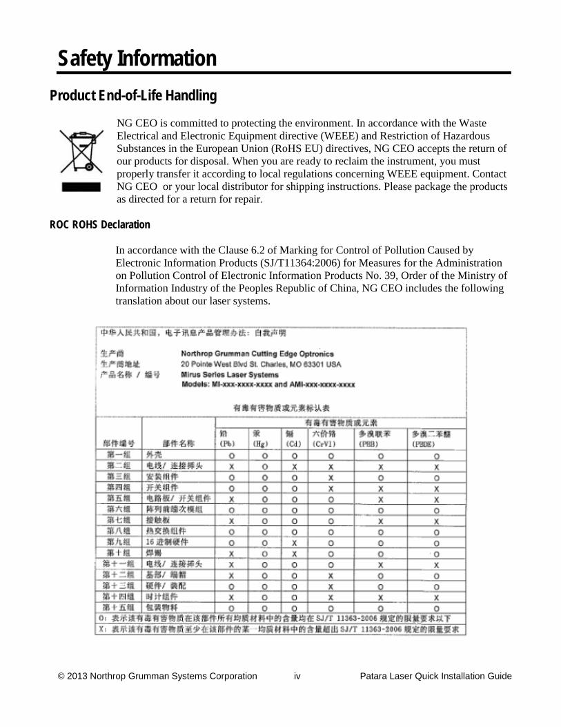
In accordance with the Clause 6.2 of Marking for Control of Pollution Caused by Electronic Information Products (SJ/T11364:2006) for Measures for the Administration on Pollution Control of Electronic Information Products No. 39, Order of the Ministry of Information Industry of the Peoples Republic of China, NG CEO includes the following translation about our laser systems.
© 2013 Northrop Grumman Systems Corporation v Patara Laser Quick Installation Guide
Conventions
The following conventions appear in this manual:
This icon denotes a caution or a warning, which advise you of precautions to take to avoid injury, data loss, or a system crash.
Initial Capped The first letter in uppercase refers to menu options, e.g., Phase Delay, Pulse Width.
CAPS Front-panel buttons, knobs, and connectors appear in all uppercase letters, e.g., MENU, CURRENT
.
The symbol separates a sequence of button pushes, e.g., MENU CHANNEL SETUP PULSE WIDTH means that you push the MENU button, then push the CHANNEL SETUP soft key, and then push the PULSE WIDTH soft key.
Italic text denotes references to other resources that may be helpful to you or to bring attention to important information.
italic
This icon denotes a note, which alerts you to important information.
I O
Power Switch Position Symbols I = On O = Off
The following conventions may appear on the product:
An injury hazard immediately accessible as you read the marking. DANGER
A hazard not immediately accessible as you read the marking. WARNING
A hazard to property including the product. CAUTION
ESD: Handle Appropriately
© 2013 Northrop Grumman Systems Corporation vi Patara Laser Quick Installation Guide
Laser Emission: Use caution.
Shock Hazard: Use caution.
Caution: Risk of danger. Refer to manual.
Chassis Ground

© 2013 Northrop Grumman Systems Corporation vii Patara Laser Quick Installation Guide
General Safety Summary The Patara emits laser radiation that can permanently damage eyes and skin, ignite fires, and vaporize substances. Please read the chapters about safety in the laser user manual, eDrive manual, power supply manual, TEC driver manual and chiller manual.
Do not open the factory packaging before carefully reading this complete quick installation guide. If you have any questions on the product which have not been discussed sufficiently within this document, contact the manufacturer for complete instructions. Failure to heed this warning may result in the destruction or serious damage to the device, and will void the product warranty.
Northrop Grumman Aerospace Systems Cutting Edge Optronics (NG CEO) recommends that a technician from NG CEO perform the installation of the laser for the first time. Only qualified technicians should be allowed to perform the installation and maintenance of the laser. If you do plan to install your laser, please use the following procedures.
Use the form in Appendix A: Customer Service to describe issues with the laser. We also suggest that you record information about the laser such as power, settings, time and date.
Safety Overview Safe operation of any laser should be reviewed prior to any new installation of the Patara laser.
CAUTION.
Follow the instructions contained in this manual for proper installation and safe operation of your laser. We recommend the use of protective eyewear at all times (the type of eyewear depends on the energy and wavelength of the laser beam and operating conditions). Consult ANSI, ACGIH, or OSHA standards for guidance.
This laser is a Class IV, high power laser whose beam is, by definition, a safety hazard. Avoid eye or skin exposure to direct or scattered laser radiation. Avoid direct viewing of the beam or its specular reflection.
CAUTION.
Use of controls, adjustments or performance of procedures other than those specified herein may result in hazardous radiation exposure.
WARNING. At all times during installation, operation, maintenance, or service of your laser, avoid exposure to laser or collateral radiation exceeding the accessible emission limits listed in “Performance Standards for Laser Products,” U.S. Code of Federal Regulations, 21 CFR 1040 10(d).
© 2013 Northrop Grumman Systems Corporation viii Patara Laser Quick Installation Guide
Precautions for Safe Operation Avoid looking directly into the laser beam or at specular reflection, even with
protective eye wear on.
Wear laser safety eyewear that is optically dense at the wavelengths of operation (798-816 nm pump light, 1064 nm fundamental, 532 nm second harmonic).
Provide a controlled access area for laser operation and limit access to those trained in laser safety principles.
Post warning signs in prominent locations near the laser operation area.
Use safety interlocks on all entryways. All NG CEO system control electronics are supplied with interlock inputs that can be used to preclude operation with an open safety door.
Enclose beam paths wherever possible.
Set up experiments so the laser beam is below eye level.
Work in an area that is well lighted to avoid dilation of pupils.
Set up a target for the beam.
Set up shields to prevent reflected beams from escaping the laser operation area.
View an infrared laser beam with a protected image converter at an oblique angle reflecting from a diffuse surface.
Ensure that all electrical connections are made in a safe manner.
Position equipment so that electrical connections are shielded from accidental touch.
Do not smoke, eat, or drink in laser areas.
Avoid leaving an operating laser unattended.

© 2013 Northrop Grumman Systems Corporation ix Patara Laser Quick Installation Guide
About this Manual This Quick Installation Guide describes the unpacking, set-up, initial operation and optimization of the Patara Laser system. The Guide consists of the following chapters:
Chapter 1: Laser System Components provides a description of the system components and unpacking procedures
Chapter 2: Laser System Setup provides information on quick set-up of the laser head
Chapter 3: Laser Operation and Tuning provides information on initial operation and optimizing the laser performance
Appendix A: Customer Service provides information to expedite any service request before contacting NG CEO.
© 2013 Northrop Grumman Systems Corporation x Patara Laser Quick Installation Guide
Table of Contents Chapter 1: Laser System Components 1
System Components 2
Unpacking 2
Chapter 2: Laser System Setup 4
Laser head setup 5
eDrive setup 5
DC power supply setup 6
Chiller setup 8
Cables connections 10
Chapter 3: Laser Operation and Tuning 19
First-time chiller turn-on procedure 20
First time laser turn-on procedure 21
Laser Performance Optimization 25
Laser Operation Considerations 28
Daily Operation 29
Appendix A: Customer Service 31
Questions 32

© 2013 Northrop Grumman Systems Corporation xi Patara Laser Quick Installation Guide
Table of Figures Figure 1-1 Components for the Patara laser PA-100-QMG and PA-200-QMG 2
Figure 2-1 Basic setup for the laser power test. 5
Table 2-1 Input Power Fuse 5
Table 2-2 DC Power Supply for PA-100-GMQ, DCS60-50E 7
Table 2-3 DC Power Supply for PA-200-GMQ, DLM80-50E 7
Figure 2-2 Diagram of Water Hoses and Filter Connections 9
Figure 2-3 Power connection on the Chiller 10
Figure 2-4 Connectors on the back panel of the Patara laser (Model Pa-100-QMG and PA-200-QMG). 10
Figure 2-5 Laser Head Coolant Lines 11
Figure 2-6 Laser Head Signal Connection 11
Figure 2-7 Laser Head RF Connection 11
Figure 2-8 Laser Head Power Connection 12
Figure 2-9 Power Detector Components 12
Figure 2-10 Power Detector Head 12
Figure 2-11 Completed Assembly 13
Figure 2-12 Attenuator Components 14
Figure 2-13 Laser Signal Cable 15
Figure 2-14 RF Signal Cables 15
Figure 2-15 Chiller Interlock Connector 15
Figure 2-16 White Interlock Connectors 16
Figure 2-17 BNC Interlock Connection 16
Figure 2-18 Input Power and Array Output Power 16

© 2013 Northrop Grumman Systems Corporation xii Patara Laser Quick Installation Guide
Figure 2-19 Input Power from Power Supply 17
Figure 2-20 Array Output to Laser 17
Figure 2-21 Protection Cover 17
Figure 2-22 Positive and negative connections 17
Figure 2-23 Heat shrink over connections 18
Figure 2-24 Incoming power connections 18
Figure 3-1 Output Window Cover 21
Table 3-1 eDrive Settings 23
Figure 3-2. Example of Power Dependence of the PA-100-QMG to SHG Crystal Temperature 26
Figure 3-3. Accessible Holes for HR and HM Cavity Mirror Adjustment 27
1
© 2013 Northrop Grumman Systems Corporation 1 Patara Laser Quick Installation Guide
Chapter 1: Laser System Components This introduction provides the following information:
System Components
Unpacking

Chapter 1: Laser System Components
© 2013 Northrop Grumman Systems Corporation 2 Patara Laser Quick Installation Guide
System Components Before installation of the laser, it is recommended that you first familiarize yourself with all of the laser components as pictured below. The components for the Patara laser PA-100-QMG and PA-200-QMG are listed in figure 1-1. The power cords for the chiller and DC power supply are not shown in the picture.
Laser head Chiller eDrive
DC Power Supply AC Power Cables Laser Signal Cable
Diode Power Cable Q-Switch RF Cable Hose for Chiller
Filter housing and Filter Attenuator Controller Parts
(optional) Power Monitor Parts (optional)
Figure 1-1 Components for the Patara laser PA-100-QMG and PA-200-QMG
Unpacking Your NG CEO Patara laser was carefully packed for shipment. If its carton appears to have been damaged in transit, have the shipper’s agent present when you unpack.
Inspect the unit as you unpack it, looking for dents, scratches, or other evidence of damage. If you discover any damage, immediately file a claim against the carrier and

Chapter 1: Laser System Components
© 2013 Northrop Grumman Systems Corporation 3 Patara Laser Quick Installation Guide
notify NG CEO technical service. NG CEO will arrange for repair without waiting for settlement of your claim.
Keep the shipping container. If you file a damage claim, you may need it to demonstrate that the damage occurred as a result of shipping. If you need to return the unit for service, the specially designed carton assures adequate protection.
A standard Patara laser system consists of:
PA-100-QMG PA-200-QMG PA-100-QMG Laser Head PA-200-QMG Laser Head
eDrive, P/N ED4C-AXA-XXXXD-0151 eDrive, P/N ED4C-AXA-XXXXD-0151
DC Power supply, P/N DCS60-50E (200-250 VAC Single Phase, 190-250 VAC Three
Phase)
DC Power supply, P/N DLM80-50E (180-264 VAC Three Phase)
DC Power supply, P/N DLM80-50EM1 (345-445 VAC Three Phase)
DC Power supply, P/N DLM80-50EM2 (432-528 VAC Three Phase)
60 Hz Chiller P/N 6762T41CE30D 60 Hz Chiller P/N 6162T41CE30D 50 Hz Chiller P/N 6152T41CE30E 50 Hz Chiller P/N 6852T66CE70E
Laser Signal Cable Laser Signal Cable RF Cables RF Cables
Hoses and Filter for Chiller Hoses and Filter for Chiller US Power Cords for Chiller and Power Supply US Power Cords for Chiller and Power Supply
US Power Cord for eDrive US Power Cord for eDrive Desiccant Cartridge Desiccant Cartridge (2) Desiccant Refills (2) Desiccant Refills
Power Detector Head (Optional) Power Detector Head (Optional) Attenuator (Optional) Attenuator (Optional)
Please check the contents against the packing list and the sales order.

2
© 2013 Northrop Grumman Systems Corporation 4 Patara Laser Quick Installation Guide
Chapter 2: Laser System Setup Sections included in this chapter provide the following information:
Laser Head Setup
eDrive Setup
DC Power Supply Setup
Chiller Setup
Cable Connections
Chapter 2: Laser System Setup
© 2013 Northrop Grumman Systems Corporation 5 Patara Laser Quick Installation Guide
Laser head setup
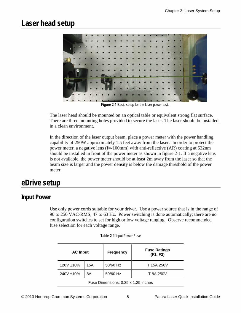
Figure 2-1 Basic setup for the laser power test.
The laser head should be mounted on an optical table or equivalent strong flat surface. There are three mounting holes provided to secure the laser. The laser should be installed in a clean environment.
In the direction of the laser output beam, place a power meter with the power handling capability of 250W approximately 1.5 feet away from the laser. In order to protect the power meter, a negative lens (f=-100mm) with anti-reflective (AR) coating at 532nm should be installed in front of the power meter as shown in figure 2-1. If a negative lens is not available, the power meter should be at least 2m away from the laser so that the beam size is larger and the power density is below the damage threshold of the power meter.
eDrive setup Input Power
Use only power cords suitable for your driver. Use a power source that is in the range of 90 to 250 VAC-RMS, 47 to 63 Hz. Power switching is done automatically; there are no configuration switches to set for high or low voltage ranging. Observe recommended fuse selection for each voltage range.
Table 2-1 Input Power Fuse
AC Input Frequency Fuse Ratings (F1, F2)
120V ±10% 15A 50/60 Hz T 15A 250V
240V ±10% 8A 50/60 Hz T 8A 250V
Fuse Dimensions: 0.25 x 1.25 inches

Chapter 2: Laser System Setup
© 2013 Northrop Grumman Systems Corporation 6 Patara Laser Quick Installation Guide
Mounting
There are four holes on the front panel of the eDrive designed for the mounting into an EIA-310D-compliant rack. If this option is used, the eDrive’s weight requires you use extra side supports. If the eDrive is to be used on a desktop or table top, it is recommended that the eDrive be equipped with feet to prevent the driver from marring the surface when it is moved. The eDrive must be secured.
Clearance
Adequate clearance should be allowed on the front, sides, and rear of the eDrive for access to connections and components. The front and rear vents of the eDrive must be a minimum of 24 inches (61 cm) away from walls or vertical surfaces so air flow is not restricted.
DC power supply setup Location, Mounting and Ventilation
The power supply may be used in rack mounted or in bench top applications. In either case, you must allow at least 1U (1.75“) clearance for cooling air to reach the ventilation inlets on the top of each unit. You must also allow sufficient space for unobstructed airflow on each side and rear of all units so that the operating ambient temperature is within specification. See Power Supply manual for additional information.
CAUTION.
Obstructing the air inlets and/or exhaust may cause fire and irreversible damage to the unit.
Unit Dimensions
The dimension of the DC power supply for the PA-100-QMG is 3.5 in x19 in x18 in (88 mm x482 mm x508 mm). The weight is 35 lbs (16 kg).
The dimension of the DC power supply for the PA-200-QMG is 3.5 in x19 in x18 in (88 mm x482 mm x508 mm). The weight is 40 lbs (18.2 kg).
Rack Mounting
The supply is designed to fit in a standard 19” equipment rack. Bolt holes in the chassis sides are provided for rack mount slides such as the ZERO #C300S18 slides. When installing the unit in a rack, be sure to provide adequate support for the rear of the unit

Chapter 2: Laser System Setup
© 2013 Northrop Grumman Systems Corporation 7 Patara Laser Quick Installation Guide
while not obstructing the ventilation on the top, sides and rear of all units. See Power Supply manual for additional information.
CAUTION.
Rack mounting bolts must not extend more than 3/16" into the side of the power supply.
AC INPUT POWER Requirements
The AC Input Power Connection section of the power supply manual gives instructions for making connections to three phase AC power sources. Before you can use the power supply, you must determine your AC input power requirements and assemble an appropriate line cord and connector. The power supply is shipped with a kit of connector and strain relief parts which you assemble using the procedures in the section.
The specifications for input voltage, current, and frequency are listed below. The DCS60-50E can be wired in either configuration shown in Table 2-1. The DLM80-50E must be purchased with the correct input voltage option.
Table 2-2 DC Power Supply for PA-100-GMQ, DCS60-50E
Output Power Input Range (47–63 Hz)
Input Current
Maximum
3 kW 200–250 VAC Single–Phase
20A RMS
3 kW 190–250 VAC Three–Phase
14A RMS
Table 2-3 DC Power Supply for PA-200-GMQ, DLM80-50E
Output Power Nominal Input Voltage
Input Option
Input Range (47–63 Hz)
Input Current
Maximum
AC Input Terminals
4 kW 208 VAC Three–Phase
Std 180–264 VAC L–L
15A RMS L1–L2–L3 (F1–F2–F3)
4 kW 380/400/415 VAC Three–Phase
M1 345–455 VAC L–L
8.5A RMS L1–L2–L3 (F1–F2–F3)
4 kW 480 VAC Three–Phase
M2 432–528 VAC L–L
6.5A RMS L1–L2–L3 (F1–F2–F3)

Chapter 2: Laser System Setup
© 2013 Northrop Grumman Systems Corporation 8 Patara Laser Quick Installation Guide
Chiller setup Ambient Temperature and Relative Humidity
The Chiller is designed for indoor installation in ambient temperatures between 7° and 30°C (45° and 85°F; relative humidity should not exceed 80% (non-condensing).
Location
Select a level location, near the application, free from dripping or spraying moisture and excessive dust. Keeping coolant lines short allows the pump to provide maximum pressure and flow to the application. If the chiller will be placed more than 25 feet from the application, call PolyScience service to discuss placement and how it might affect performance.
Units with non-pressurized reservoirs should never be installed more than 25 feet below the process or overflow may occur. Distances may vary slightly due to elevations above sea level. Call 800-229-7569 for more information.
Oxygen Depletion Risk
In the event of a refrigerant leak, refrigerant gas may displace oxygen that could result in suffocation and death. Never place the chiller in a room that is smaller than the minimum room volume requirement as defined below. If the room is ventilated, the air distribution system must be analyzed to determine the worst case distribution of leaked refrigerant. A leak detector alarm device is always required in a ventilated room that does not meet the minimum room volume given below. Assure adequate and sufficient room volume and ventilation before placing a chiller that contains refrigerant in a room. Contact Polyscience at 800-229-7569 if you have any concerns or questions.
Pounds of refrigerant charge can be read directly from the nameplate on your chiller. Remember to include in your calculation any refrigerant that may be stored in any other containers.
Minimum Room Volume = Pounds of refrigerant x 110 cubic feet
Example: Two chillers are placed in a room, each containing 6 pounds of refrigerant. The minimum room volume shall be 12 x 110 cubic feet, or 1,320 cubic feet.
Clearance
Adequate clearance should be allowed on the front, sides, and rear of the chiller for access to connections and components. The cabinet of the chiller is designed to vent air. Maintain free space, equal to the height of the chiller, for flow of air on the condenser side of the chiller (opposite to where the coolant lines connect). The two sides or the top must have an equal amount of free space. When air flow becomes impeded, cooling capacity decreases and electrical efficiency drops as motor load increases.

Chapter 2: Laser System Setup
© 2013 Northrop Grumman Systems Corporation 9 Patara Laser Quick Installation Guide
Electrical Power
Connect the chiller, in compliance with the National Electric Code (NEMA 6-30R) for American usage and IEC 127 for European usage as well as local codes, to a fused disconnect box. Maximum fuse sizes in the disconnect box must not exceed the maximum ratings specified on the serial tag of the chiller (found on the electrical box). The voltage, phase, and frequency of the power source must also match the requirements specified on the serial tag.
CAUTION.
The chiller has been set 208-230 Volts at the factory for 60-Hertz single phase or 200 volts for 50-Hertz single phase. High voltages out of the specified range could damage the chiller.
WARNING.
DO NOT plug the Chiller into the electrical outlet until the unit is ready for Startup.
Chiller Connections
The required water hoses, filters, and fittings are included in the plumbing kit that was shipped with your laser. They should be connected as illustrated in the figures below. The correct water flow path starts with the supply port of the chillerfilter coolant in port of laser headlaser headcoolant out port of laser head return port of the chiller. Please be aware of the flow direction of the filter.
Figure 2-2 Diagram of Water Hoses and Filter Connections
The filter may be attached to the back of the chiller, customer’s equipment or a wall using the provided L-bracket.

Chapter 2: Laser System Setup
© 2013 Northrop Grumman Systems Corporation 10 Patara Laser Quick Installation Guide
Connect power to the chiller.
Figure 2-3 Power connection on the Chiller
Cables connections Connections on the laser head
Figure 2-4 Connectors on the back panel of the Patara laser (Model Pa-100-QMG and PA-200-QMG).
Figure 2-4 shows all of the connectors on the back panel of the Patara laser. All of the connectors are clearly labeled. The steps for the installation follow.
1. Plumbing Connection: Push the barb fittings of water hoses connectors gently into the COOLANT IN and COOLANT OUT ports by following the flow patch direction. Wetting the o-rings of the quick disconnect fittings and receptacles can prevent the o-ring from being cut by the mating piece during insertion. Make sure that the quick disconnect fittings are locked. A click is heard once it is locked.

Chapter 2: Laser System Setup
© 2013 Northrop Grumman Systems Corporation 11 Patara Laser Quick Installation Guide
Figure 2-5 Laser Head Coolant Lines
2. Signal Connection: Align the female connector of the laser signal cable to the J1 connector on the laser head. Once it is aligned, the connector can be pushed in. Turn the locking ring of the connector in the clockwise direction until it is locked.
Figure 2-6 Laser Head Signal Connection
3. RF Connection: Connect the Q-switch RF cables to the BNC connectors on the laser head accordingly. The connector should be locked as well by turning it clockwise until it stops.
Figure 2-7 Laser Head RF Connection

Chapter 2: Laser System Setup
© 2013 Northrop Grumman Systems Corporation 12 Patara Laser Quick Installation Guide
4. Diode Power Connection: Connect the female connector of the diode power cable to the J2 connector on the laser head.
Figure 2-8 Laser Head Power Connection
5. Power Detector Head: Follow the steps below to attach the Power Detector Head (Figure 2-9 and 2-10) onto the side of the laser.
Figure 2-9 Power Detector Components Figure 2-10 Power Detector Head
1. Loosen Screws 2. Remove Connector 3. Remove Cap
4. Install Connector 5. Tighten Connector 6. Align Pins

Chapter 2: Laser System Setup
© 2013 Northrop Grumman Systems Corporation 13 Patara Laser Quick Installation Guide
7. Install Detector 8. Tighten Detector Head 9. Connect DC power Cable
to Detecor Head
10. Connect BNC to Laser
Head 11. Connect 9 Pin Connector 12. Connect USB
Figure 2-11 Completed Assembly
With installation of the software provided with the kit, and a USB connection to a PC, the power can be read on the computer. Please refer to the Power Detector Head manual on the provided USB thumb drive for details.
Chapter 2: Laser System Setup
© 2013 Northrop Grumman Systems Corporation 14 Patara Laser Quick Installation Guide
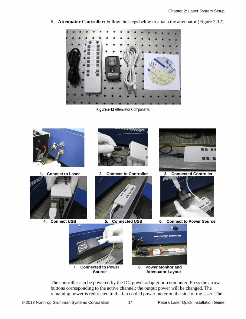
6. Attenuator Controller: Follow the steps below to attach the attenuator (Figure 2-12)
Figure 2-12 Attenuator Components
1. Connect to Laser 2. Connect to Controller 3. Connected Controller
4. Connect USB 5. Connected USB 6. Connect to Power Source
7. Connected to Power
Source 8. Power Monitor and
Attenuator Layout
The controller can be powered by the DC power adapter or a computer. Press the arrow buttons corresponding to the active channel; the output power will be changed. The remaining power is redirected to the fan cooled power meter on the side of the laser. The

Chapter 2: Laser System Setup
© 2013 Northrop Grumman Systems Corporation 15 Patara Laser Quick Installation Guide
maximum power allowed for the side-mounted fan cooled power meter is 200W. If the temperature of the power meter exceeds 60 degree C, the laser will be shut off to protect power meter. Please read the attenuator manual on the provided CD for detailed setup.
Connections on the eDrive
1. Laser Signal Connection: Connect the male connector of laser signal cable to the receptacle labeled LASER INTERFACE on the back of eDrive.
Figure 2-13 Laser Signal Cable
2. RF Signal Connection: Connect the QS RF cables to the RF OUT 1 and rf out 2
connectors as shown below.
Figure 2-14 RF Signal Cables
3. Chiller Interlock Connection: Connect the 9 pin chiller interlock shorting connector as shown below.
Figure 2-15 Chiller Interlock Connector

Chapter 2: Laser System Setup
© 2013 Northrop Grumman Systems Corporation 16 Patara Laser Quick Installation Guide
4. White Interlock Connection: Connect the 2 pin white interlock shorting connector as shown below.
Figure 2-16 White Interlock Connectors
5. Interlock Shorting BNC Connection: Connect the 3 BNC shorting connectors to TRIGGER/GATE IN, QSW THERM INTLK, and INTERLOCK as shown below.
Figure 2-17 BNC Interlock Connection
6. The cables from DC power supply go to the terminals labeled with INPUT POWER while the Diode Power cable from the laser head is connected to the terminals of ARRAY OUTPUT. Please be careful with the polarity of the terminals.
Figure 2-18 Input Power and Array Output Power

Chapter 2: Laser System Setup
© 2013 Northrop Grumman Systems Corporation 17 Patara Laser Quick Installation Guide
Figure 2-19 Input Power from Power Supply Figure 2-20 Array Output to Laser
7. Protection Cover: Once all the power cables are connected, the protection cover has to be installed as shown below.
Figure 2-21 Protection Cover
Connections on the Power Supply
1. Power to eDrive Connection: Connect the positive (red) and negative (black) cables from the eDrive to the power supply as shown below. Prior to making the connection, place heat shrink over the cable and slide it down the cable.
DCS60-50E for PA-100-QMG. DLM80-50E for PA-200-QMG.
Figure 2-22 Positive and negative connections

Chapter 2: Laser System Setup
© 2013 Northrop Grumman Systems Corporation 18 Patara Laser Quick Installation Guide
2. Heat shrink: Slide the heat shrink pieces over the connections. DCS60-50E for PA-100-QMG DLM80-50E for PA-200-QMG
Figure 2-23 Heat shrink over connections
3. Incoming Power: With the power cable disconnected from the wall, attach the 4 wires from the power cable as shown below. Refer to the DC Power Supply manual for details.
DCS60-50E for PA-100-QMG DLM80-50E for PA-200-QMG
Figure 2-24 Incoming power connections

3
© 2013 Northrop Grumman Systems Corporation 19 Patara Laser Quick Installation Guide
Chapter 3: Laser Operation and Tuning This chapter describes the initial operation and tuning of your Laser system. This chapter discusses:
Initial Turn on
Internal Trigger
External Q-switch Trigger
Laser Performance Optimization
Laser Turn off

Chapter 3: Laser Operation and Tuning
© 2013 Northrop Grumman Systems Corporation 20 Patara Laser Quick Installation Guide
First-time chiller turn-on procedure The first-time turn-on procedure should be similar for use with other chillers.
Filling the Reservoir
1. Remove the filler cap from the reservoir
2. Using a funnel, add Optishield Plus mixture (90% distilled water, 10% Optishield Plus) until it reaches the MAX line on the reservoir’s fluid level gauge.
3. When full, remove the funnel, but do not replace the cap at this time.
Electrical Power
4. Plug the Chiller’s power cord into an appropriate electrical outlet. Place the Circuit Breaker/Power Switch on the rear of the instrument enclosure to the On
5. Three decimal points will appear on the Temperature display
position.
Starting Process Fluid Flow
6. Press the Power
7. The pump will turn on and fluid will begin circulating through the system. The set point temperature will appear briefly on the Temperature display; after a few seconds, it will be replaced by the actual fluid temperature.
Button on the front panel. The system startup sequence will begin and proceed as follows:
Check for leaks
8. Once the pump is turned on, check all of the connectors to see if there is any leakage. If a leak is observed, turn off the pump immediately and fix the leak.
9. The reservoir’s fluid level will drop as the process and/or process cooling lines fill with fluid. Slowly add fluid to the reservoir until the liquid level remains stable.
10. Replace the reservoir cap
Chapter 3: Laser Operation and Tuning
© 2013 Northrop Grumman Systems Corporation 21 Patara Laser Quick Installation Guide
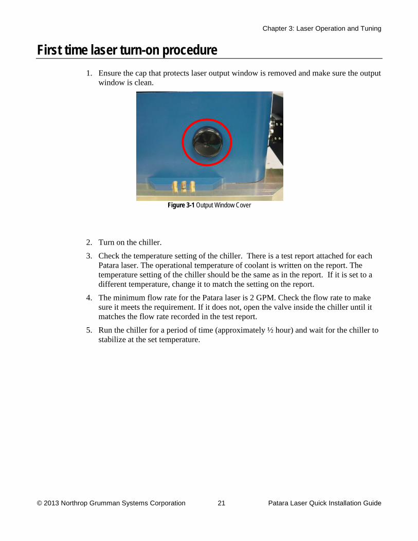
First time laser turn-on procedure 1. Ensure the cap that protects laser output window is removed and make sure the output
window is clean.
Figure 3-1 Output Window Cover
2. Turn on the chiller.
3. Check the temperature setting of the chiller. There is a test report attached for each Patara laser. The operational temperature of coolant is written on the report. The temperature setting of the chiller should be the same as in the report. If it is set to a different temperature, change it to match the setting on the report.
4. The minimum flow rate for the Patara laser is 2 GPM. Check the flow rate to make sure it meets the requirement. If it does not, open the valve inside the chiller until it matches the flow rate recorded in the test report.
5. Run the chiller for a period of time (approximately ½ hour) and wait for the chiller to stabilize at the set temperature.
Chapter 3: Laser Operation and Tuning
© 2013 Northrop Grumman Systems Corporation 22 Patara Laser Quick Installation Guide
DC power supply
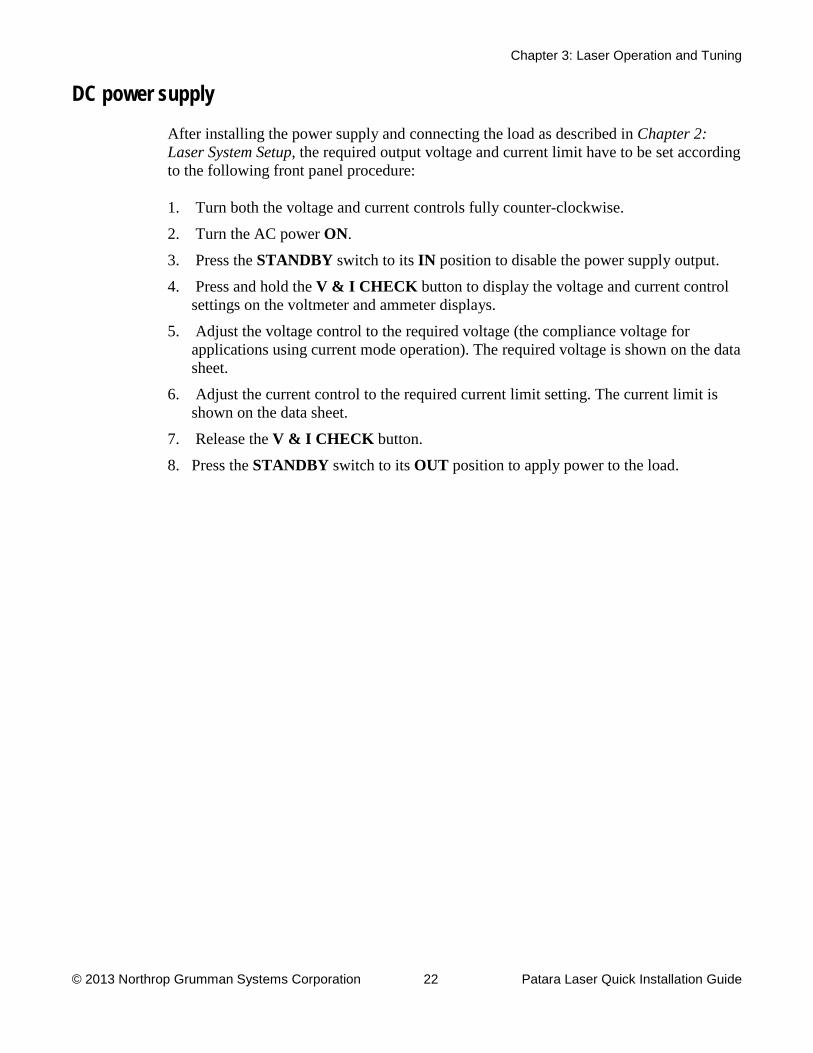
After installing the power supply and connecting the load as described in Chapter 2: Laser System Setup, the required output voltage and current limit have to be set according to the following front panel procedure:
1. Turn both the voltage and current controls fully counter-clockwise.
2. Turn the AC power ON3. Press the
.
STANDBY switch to its IN4. Press and hold the
position to disable the power supply output.
V & I CHECK
5. Adjust the voltage control to the required voltage (the compliance voltage for applications using current mode operation). The required voltage is shown on the data sheet.
button to display the voltage and current control settings on the voltmeter and ammeter displays.
6. Adjust the current control to the required current limit setting. The current limit is shown on the data sheet.
7. Release the V & I CHECK8. Press the
button.
STANDBY switch to its OUT
position to apply power to the load.

Chapter 3: Laser Operation and Tuning
© 2013 Northrop Grumman Systems Corporation 23 Patara Laser Quick Installation Guide
Turn on and check the settings of the eDrive
1. Flip the power switch on the back panel of the eDrive to the ON
2. Make sure that the red
or I position.
EMERGENCY button is released. Turn on the eDrive by turning the key to ON position and pressing the POWER
3. Check all the laser parameters in the eDrive. The menu designations will help locate the settings. Use the following values for the Patara laser
button to power up the eDrive.
Table 3-1 eDrive Settings
Menu 1 Menu 2 Menu 3 Parameter Setting or Value Channel Setup
Internal Trigger Enabled
Channel Setup Q-Switch
Q Switch (QS) Enabled
Set Fequency refer to test report
Set Window Width 5 µs
Set Q-Switch Power 100%
Channel Setup Q-Switch Set FPS Settings
FPS Enabled FPS Mode Standard FPS Delay refer to test report Start Power refer to test report FPS Widow Length refer to test report FPS Modulation Type refer to test report PPK Open Offset 0
PPK Closed Offset 0
Channel Setup Channel 1
Channel 1 Enabled
Set Current refer to test report
Set Standby Current refer to test report
Set Slew Rate refer to test report
Slew Control Enabled
Set Current Limit refer to test report
Channel Setup Channel 1 Fault Setup Set Voltage Dropout 20 V Set Current Tolerance Enabled
Set Current Tolerance 4 A

Chapter 3: Laser Operation and Tuning
© 2013 Northrop Grumman Systems Corporation 24 Patara Laser Quick Installation Guide
Menu 1 Menu 2 Menu 3 Parameter Setting or Value Comm Setup Channel 0 Setup Set Function Function Oven TEC
Channel Setup Comm 0
Set Temp See Test Report
Set Tolerance Range +1.5C
Set output voltage refer to test report
Set Min Temp +22.0C
Set Max Temp +45.0C
Set P Const. refer to test report
Set I Const refer to test report
Set D Const refer to test report
Set Control Function H-BRIDGE
Set Heat Mult. 1.000
Set Cool Mult 1.000
Sensor Type TS67
Sensor Offset 0
TEC Enabled (Note: must be done last) Enabled
Interface Setup Set Trig Out Mode Trig out mode QSW Active High
Interface Setup Shutter Setup Shutter FPS Enabled Shutter Speed 14 ms Closed to Standby Enabled
Interface Setup Marking Mode Setup
LM Active Low Gate Active High FPS Active High
Utility Functions Manual Lockout Disabled
Utility Functions Humidity Options Measured Current Humidity
(reads out measured humidity)
Adjust Humidity Threshold refer to test report
4. Verify that there are no objects in the laser beam path except for the negative lens and power meter.
WARNING.
5. Once all the parameters are set correctly, and temperature of the chiller is stabilized, set the current to 10A and press the
Wear proper laser safety eyewear to protect your eyes.
EMISSION6. Press the
button.
SHUTTER button to open the laser shutter. Gradually increase the current up to slightly above the threshold. Move the negative lens and power meter so that the

Chapter 3: Laser Operation and Tuning
© 2013 Northrop Grumman Systems Corporation 25 Patara Laser Quick Installation Guide
beam is going through the center of the lens and hitting the center of the power meter. Set current to achieve 30W. The current required for 30W is shown on the laser test report
7. Once the laser has reached output power around 30W, and the TEC and chiller temperatures have stabilized, gradually increase the current set point to the operating current specified in the test report. Don’t touch any part of the laser and wait for the laser to stabilize for 1 hour (usually the laser takes around 20 minutes to reach 95% of the maximum power). Then check if the power is close to the result on the test report.
Often the laser needs optimization for the first installation due to the slight differences of environments, chiller settings, and transportation vibration.
Laser Performance Optimization At this time, there should be green light coming out of the laser. If not, contact NG CEO technical service for assistance. To reach the best performance, the laser may need slight adjustments to optimize the alignment.
1. Wait for the laser to reach thermal stabilization
Both the laser bench temperature and environmental temperature significantly impact the laser power. Wait for the laser to be thermally stabilized before attempting any adjustment.
2. Check the settings of the eDrive and chiller
During installation, it is advised that the performance of the laser be checked according to the factory’s default settings. Check that all of the eDrive settings are correct.
The water flow rate and coolant temperature have a significant impact on the laser performance. Make sure that the flow rate is above 2.0 GPM and the temperature of the chiller is correct according to the test report.
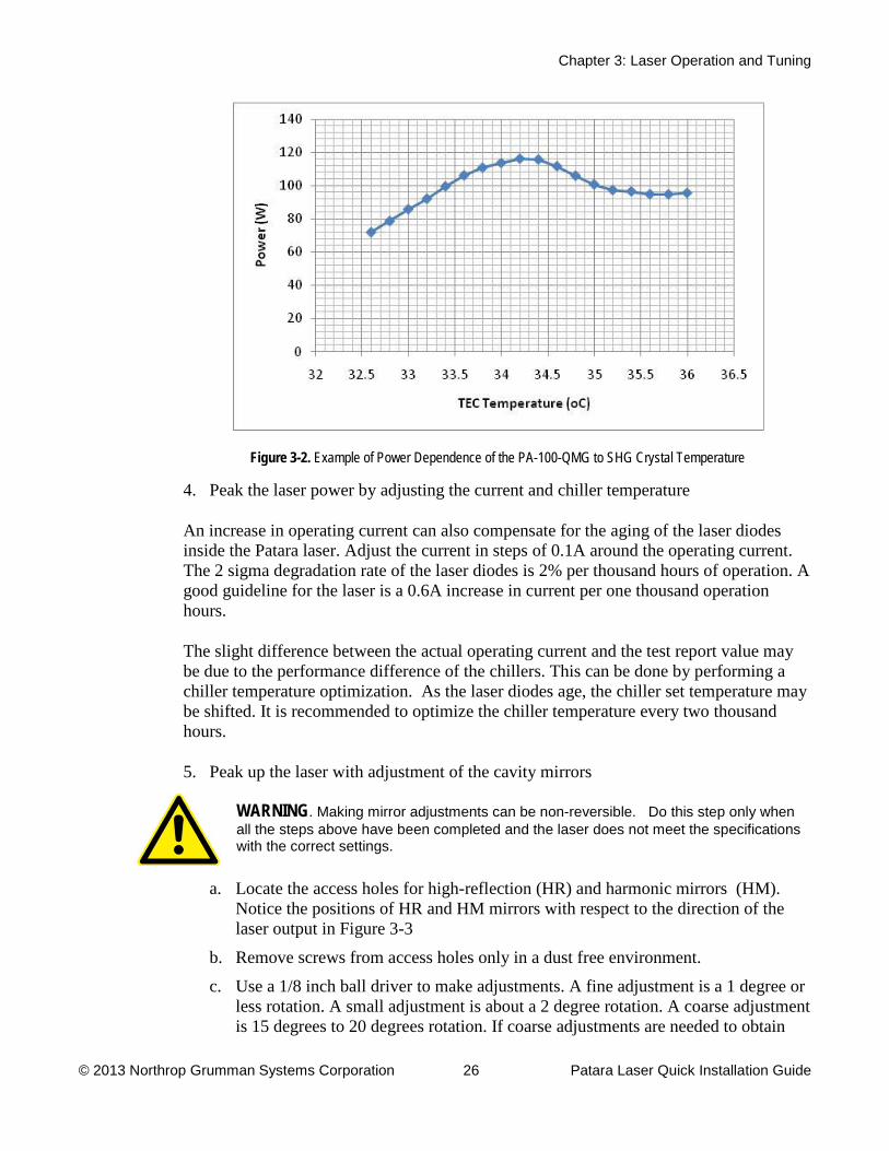
3. Peak up the laser power by adjusting the temperature of the TEC controller
The phase matching of the second harmonic generation (SHG) crystal is crucial for the Patara laser. The phase matching is controlled by setting the proper temperature on the SHG crystal. The temperature is controlled by the software of the eDrive.
Figure 3-2 shows an example of the dependence of laser power on the temperature of SHG crystal. As shown in the example, the midpoint of the temperature band is around 34.2 oC.
Chapter 3: Laser Operation and Tuning
© 2013 Northrop Grumman Systems Corporation 26 Patara Laser Quick Installation Guide
Figure 3-2. Example of Power Dependence of the PA-100-QMG to SHG Crystal Temperature
4. Peak the laser power by adjusting the current and chiller temperature
An increase in operating current can also compensate for the aging of the laser diodes inside the Patara laser. Adjust the current in steps of 0.1A around the operating current. The 2 sigma degradation rate of the laser diodes is 2% per thousand hours of operation. A good guideline for the laser is a 0.6A increase in current per one thousand operation hours.
The slight difference between the actual operating current and the test report value may be due to the performance difference of the chillers. This can be done by performing a chiller temperature optimization. As the laser diodes age, the chiller set temperature may be shifted. It is recommended to optimize the chiller temperature every two thousand hours.
5. Peak up the laser with adjustment of the cavity mirrors
WARNING
a. Locate the access holes for high-reflection (HR) and harmonic mirrors (HM). Notice the positions of HR and HM mirrors with respect to the direction of the laser output in Figure 3-3
. Making mirror adjustments can be non-reversible. Do this step only when all the steps above have been completed and the laser does not meet the specifications with the correct settings.
b. Remove screws from access holes only in a dust free environment.
c. Use a 1/8 inch ball driver to make adjustments. A fine adjustment is a 1 degree or less rotation. A small adjustment is about a 2 degree rotation. A coarse adjustment is 15 degrees to 20 degrees rotation. If coarse adjustments are needed to obtain
Chapter 3: Laser Operation and Tuning
© 2013 Northrop Grumman Systems Corporation 27 Patara Laser Quick Installation Guide
performance, reduce operating current by 2 A. Return to normal operating current when making small and fine adjustments.
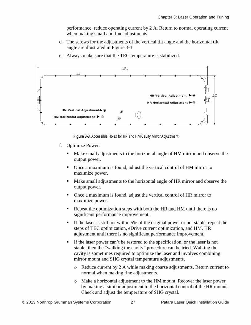
d. The screws for the adjustments of the vertical tilt angle and the horizontal tilt angle are illustrated in Figure 3-3
e. Always make sure that the TEC temperature is stabilized.
Figure 3-3. Accessible Holes for HR and HM Cavity Mirror Adjustment
f. Optimize Power:
Make small adjustments to the horizontal angle of HM mirror and observe the output power.
Once a maximum is found, adjust the vertical control of HM mirror to maximize power.
Make small adjustments to the horizontal angle of HR mirror and observe the output power.
Once a maximum is found, adjust the vertical control of HR mirror to maximize power.
Repeat the optimization steps with both the HR and HM until there is no significant performance improvement.
If the laser is still not within 5% of the original power or not stable, repeat the steps of TEC optimization, eDrive current optimization, and HM, HR adjustment until there is no significant performance improvement.
If the laser power can’t be restored to the specification, or the laser is not stable, then the “walking the cavity” procedure can be tried. Walking the cavity is sometimes required to optimize the laser and involves combining mirror mount and SHG crystal temperature adjustments.
o Reduce current by 2 A while making coarse adjustments. Return current to normal when making fine adjustments.
o Make a horizontal adjustment to the HM mount. Recover the laser power by making a similar adjustment to the horizontal control of the HR mount. Check and adjust the temperature of SHG crystal.
HM Vertical Adjustment
HM Horizontal Adjustment
HR Vertical Adjustment
HR Horizontal Adjustment

Chapter 3: Laser Operation and Tuning
© 2013 Northrop Grumman Systems Corporation 28 Patara Laser Quick Installation Guide
o Continue if improvement is noted. If there is no improvement, try the opposite direction.
o Perform the same procedure with the vertical adjustments of the HM and HR mount.
o Typically, SHG temperature adjustment is not needed when adjusting vertically. Periodically check for hold off when making these adjustments (see Check Hold Off section in Chapter 5: Maintenance of the user manual).
o If laser power is within +/-5 percent of nominal (typical power meter accuracy), and it has good beam shape and stability, stop and replace the access screws in the cover.
Laser Operation Considerations For the high power Nd:YAG laser with intra-cavity doubling, there is a significant thermal response or relaxation time for the laser crystal as well as the doubling crystal. Any large, transient pump current change has an impact on the energy storage in the laser crystal as well as thermal properties on both crystals. The extra stored energy can cause a giant Q-switch pulse that can be suppressed by the FPS feature of our eDrive. However, both laser crystal and SHG crystal need longer time to reach thermal equilibrium. This time lag can cause damage to the mirrors or the SHG crystal. To combat this problem, the ramp rate of the pump current is controlled by the eDrive, once the shutter is opened. If the application needs to stop lasing more than several seconds, it is advised that the laser beam should be directed to the place other than on the work piece or an external shutter is needed to dump the laser beam.
For the standalone laser system, the eDrive controls the ramp rate of the pump current. Therefore, one can set the laser to the operational current.
Every laser application needs a particular laser power for the best results. In some cases, the output power has to be changed at different stages even in the same laser process. Typically, the output power of a laser can be varied by changing the pump current. However, the active laser crystals can exhibit strong thermal lensing, which is related to the pump current. Variation of the pump current results in the change of the thermal lensing. Therefore, the position of the focal point moves as the pump current is varied. This is not desirable for the most of laser applications especially laser micro-machining.
The output power of Patara laser can be changed either by changing the pump current or by changing the Q-switch Power. This unique, patented technology allows users to adjust the laser output power continuously without changing the pump current. The focal point is kept at the same position regardless the power level. This feature is very useful for precision micro-machining when different power levels are required for the process. For applications that require power variation from 0%-100%, it is recommended to use an external power attenuator, for example the use of a half wave plate and a polarizer.
Chapter 3: Laser Operation and Tuning
© 2013 Northrop Grumman Systems Corporation 29 Patara Laser Quick Installation Guide
The optional external power attenuation has some advantages such as controlling output power from a few percent to full power while the pulse width, pulse stability and beam characteristic are kept the same. The side power meter works as beam dump as well as laser power monitor.
Please refer to the eDrive manual for setting the Q-switch power.
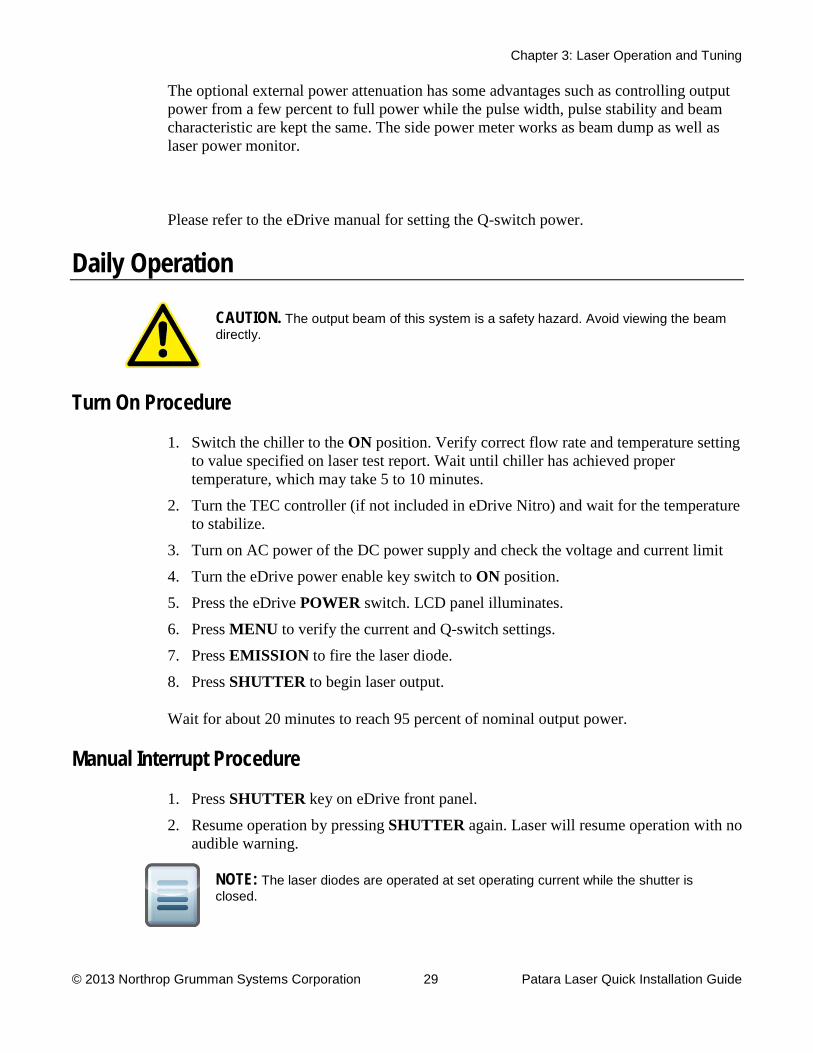
Daily Operation
CAUTION.
Turn On Procedure
The output beam of this system is a safety hazard. Avoid viewing the beam directly.
1. Switch the chiller to the ON
2. Turn the TEC controller (if not included in eDrive Nitro) and wait for the temperature to stabilize.
position. Verify correct flow rate and temperature setting to value specified on laser test report. Wait until chiller has achieved proper temperature, which may take 5 to 10 minutes.
3. Turn on AC power of the DC power supply and check the voltage and current limit
4. Turn the eDrive power enable key switch to ON 5. Press the eDrive
position.
POWER6. Press
switch. LCD panel illuminates.
MENU7. Press
to verify the current and Q-switch settings.
EMISSION8. Press
to fire the laser diode.
SHUTTER
Wait for about 20 minutes to reach 95 percent of nominal output power.
to begin laser output.
Manual Interrupt Procedure
1. Press SHUTTER2. Resume operation by pressing
key on eDrive front panel.
SHUTTER
again. Laser will resume operation with no audible warning.
NOTE: The laser diodes are operated at set operating current while the shutter is closed.

Chapter 3: Laser Operation and Tuning
© 2013 Northrop Grumman Systems Corporation 30 Patara Laser Quick Installation Guide
Shut Down Procedure
1. Press SHUTTER2. Press
key to stop lasing.
EMISSION3. Press
on the eDrive. The laser diodes cease emission.
POWER4. Turn the eDrive power enable key switch to
on the eDrive and hold for 5 seconds until display turns dark.
OFF5. Turn off AC power of DC power supply
.
6. Let chiller run for 1 to 2 minutes.
7. Turn off TEC controller (if not included in eDrive Nitro).
8. Turn off chiller.
Please refer to the separate eDrive User Manual for detailed operating instructions.

A
© 2013 Northrop Grumman Systems Corporation 31 Patara Laser Quick Installation Guide
Appendix A: Customer Service This form has been provided to encourage you to tell us about any difficulties you may have experienced while using your Northrop Grumman Cutting Edge Optronics instruments or user manuals. Call or write our customer service department to bring attention to problems that you may not have personally experienced. We are always interested in improving our products and manuals, and we appreciate all suggestions.
Date:
Name:
Company or Institution:
Department:
Address:
Laser Model Number: Serial Number:
Chiller Model Number: Serial Number:
eDrive Model Number: Serial Number:
Laser Manufacture Date: Total Laser Lifetime (hours):

Appendix A: Customer Service
© 2013 Northrop Grumman Systems Corporation 32 Patara Laser Quick Installation Guide
Questions What is the water flow rate (GPM)?
What is the set temperature on the chiller (o
What is the water pressure on chiller (PSI)?
C)?
What are the temperature set and actual reading from TEC controller (o
What are the set current and actual current from eDrive (A)?
C)?
Is Q-switch enabled (yes/no)?
Is Q-switch triggered internally or externally?
What is the Q-switch power (percent)?
Is FPS enabled (yes/no)?
What are the FPS parameters?
What is the pulse repetition frequency (kHz)?
Is the output power measured directly from the laser (yes/no)?
What is the measured power (W)?
When did the problem happen?
Have you changed any settings recently (yes/no)?
Have you adjusted the laser to try to fix the problem (yes/no)?

Appendix A: Customer Service
© 2013 Northrop Grumman Systems Corporation 33 Patara Laser Quick Installation Guide
What are the changes made recently to the system?
Please describe the problem or laser behavior as detailed as possible:
Suggestions
Email or fax to:
Northrop Grumman Cutting Edge Optronics, Inc. 20 Point West Boulevard Saint Charles, MO 63301 USA Phone: (636) 916-4900 Fax: (636) 916-4994 Email: [email protected]


