56
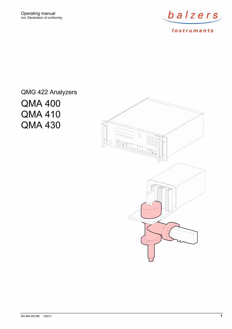
Operating manual incl. Declaration of conformity BG 800 453 BE (0001) 1 QMG 422 Analyzers QMA 400 QMA 410 QMA 430
Operating manualincl. Declaration of conformity
BG 800 453 BE (0001) 1
QMG 422 Analyzers
QMA 400QMA 410QMA 430

2 BG 800 453 BE (0001) QMA4x0.om
In all communications with Balzers Instruments, please specify the information onthe product nameplate.
For convenient reference please copy that information into the nameplate replicabelow:
Typ:
No:F-No:
This document applies to the QMA 400, QMA 410, QMA 430 with Faraday cup or90° off-axis SEM and Faraday cup and with the ion sources described in thisdocument.
If not indicated otherwise in the legends, the illustrations in this document corre -spond to the QMA 400 with 90° off-axis SEM. They apply to other types by ana-logy.
The short designation "QMA" is used for the QMA 400, QMA 410 and QMA 430.The short designation "QMH" is used for the QMH 400 and QMH 410.
In contrast to the Operating manual for the QMG 422, this manual follows thesame conventions as the Balzers QuadStar™ 422 Software documentation. Theparameters are marked by quotation marks ("...") e.g. "Resolution".
We reserve the right to make technical changes without prior notice.
The QMA 400, QMA 410 and QMA 430 Analyzers are used for gas analysis in highvacuum.
They are part of the QMG 422 mass spectrometer system and may only be usedin connection with equipment belonging to that system.
The operating instructions of all system components must be strictly followed.
→ [1] for the fundamental and functional principles and use of quadrupolemass spectrometers.
Product identification
Validity
Illustrations
Designations
Technical changes
Intended use
Functional principle
BG 800 453 BE (0001) QMA4x0.om 3
Contents
Product identification 2Validity 2Intended use 2Functional principle 2
1 Safety 51.1 Symbols used 51.2 Personnel qualifications 51.3 General safety instructions 51.4 Liability and warranty 6
2 Description 72.1 Design 72.1.1 Ion sources 82.1.2 Mass filter 82.1.3 Secondary electron multiplier 82.2 Versions 102.2.1 Cathode materials 102.2.2 Electron collimation magnet 102.2.3 90° deflection 102.2.4 Faraday cup 112.2.5 Isolated design 112.2.6 Vacuum annealed QMA 122.2.7 Extraction hood 122.2.8 Beam deflection device 122.2.9 Differential pumping 12
3 Technical data 13
4 Installation 154.1 Preparation 154.1.1 Installing the electron collimation magnets 184.2 Installation 194.3 Gas inlet system 204.4 QMH 400/410 204.5 EP 422 204.6 CP 400 204.6.1 Removing / installing the SEM connector plate 214.7 Mounting the protective tubes 214.8 Cabling 21
5 Operation 235.1 First time operation 235.2 High temperature operation 235.3 Baking the analyzer 245.3.1 Removing the connector plates 245.3.2 Mounting the connector plates 245.4 Assessing the sensitivity 245.5 Secondary electron multiplier SEM 255.5.1 Contamination 255.5.2 Low partial pressures 255.5.3 Gain factor 255.6 Surface ions 255.7 Degas 25
4 BG 800 453 BE (0001) QMA4x0.om
6 Optimization 276.1 Recommended operating modes 276.2 Test gas 286.3 Ion source parameters 286.3.1 Emission 286.3.2 Protection 296.3.3 V1 IonRef 296.3.4 V2 Cathode 296.3.5 V3 Focus 306.3.6 V4 Field Axis 306.3.7 V5 Extraction 306.3.8 V8 Reserve 306.3.9 V9 Wehnelt 306.4 V6 / V7 Deflection 316.5 Resolution 316.6 RF cable polarity 31
7 Ion sources 337.1 Axial ion source 337.2 Crossbeam ion source 357.3 Grid ion source 397.4 Two lens ion optics 417.5 Crossbeam ion source with two lens ion optics 437.6 Three lens ion optics 467.7 Crossbeam ion source with three lens ion optics 49
8 Maintenance and spare parts 53
9 Disposal 53
Appendix 54A: Literature 54
Declaration of contamination 55
Declaration of conformity 56
For cross-references within this document, the symbol ( → XY) is used, for cross-references to other documents, the symbol ( → [Z]).
BG 800 453 BE (0001) QMA4x0.om 5
1 Safety
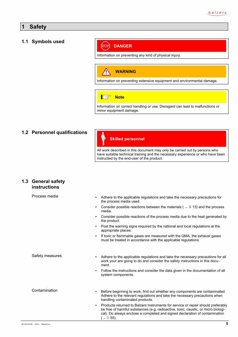
DANGER
Information on preventing any kind of physical injury.
WARNING
Information on preventing extensive equipment and environmental damage.
Note
Information on correct handling or use. Disregard can lead to malfunctions orminor equipment damage.
Skilled personnel
All work described in this document may only be carried out by persons whohave suitable technical training and the necessary experience or who have beeninstructed by the end-user of the product.
• = Adhere to the applicable regulations and take the necessary precautions forthe process media used.
• = Consider possible reactions between the materials ( → 13) and the processmedia.
• = Consider possible reactions of the process media due to the heat generated bythe product.
• = Post the warning signs required by the national and local regulations at theappropriate places.
• = If toxic or flammable gases are measured with the QMA, the exhaust gasesmust be treated in accordance with the applicable regulations.
• = Adhere to the applicable regulations and take the necessary precautions for allwork your are going to do and consider the safety instructions in this docu -ment.
• = Follow the instructions and consider the data given in the documentation of allsystem components.
• = Before beginning to work, find out whether any components are contaminated.Adhere to the relevant regulations and take the necessary precautions whenhandling contaminated products.
• = Products returned to Balzers Instruments for service or repair should preferablybe free of harmful substances (e.g. radioactive, toxic, caustic, or micro biologi-cal). Do always enclose a completed and signed declaration of contamination(→ 55).
1.1 Symbols used
1.2 Personnel qualifications
1.3 General safetyinstructions
Process media
Safety measures
Contamination
6 BG 800 453 BE (0001) QMA4x0.om
• = Adhere to the forwarding regulations of all involved countries and forwardingcompanies.
•••• ==== Communicate the safety instructions to all other users.
Balzers Instruments assumes no liability and the warranty becomes null and void ifthe end-user or third parties• = disregard the information in this document• = use the product in a non-conforming manner• = make any kind of interventions (modifications, alterations etc.) on the product• = use the product with accessories, options, and add-ons not listed in the corre -
sponding product documentation.
The end-user assumes the responsibility in conjunction with the process mediaused.
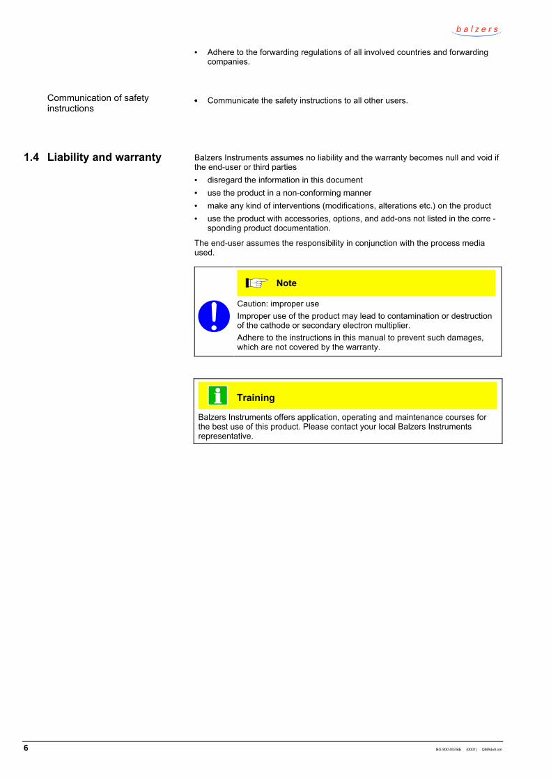
Note
Caution: improper useImproper use of the product may lead to contamination or destructionof the cathode or secondary electron multiplier.Adhere to the instructions in this manual to prevent such damages,which are not covered by the warranty.
Training
Balzers Instruments offers application, operating and maintenance courses forthe best use of this product. Please contact your local Balzers Instrumentsrepresentative.
Communication of safetyinstructions
1.4 Liability and warranty
BG 800 453 BE (0001) QMA4x0.om 7
2 Description
The fundamental principles of quadrupole mass spectrometers are explained in[1].
Chapter "Overview" in [2] shows the complete system and contains short de -scriptions of the individual components.
The analyzers QMA 400, QMA 410, and QMA 430 are the sensors of theQMG 422 mass spectrometer system.
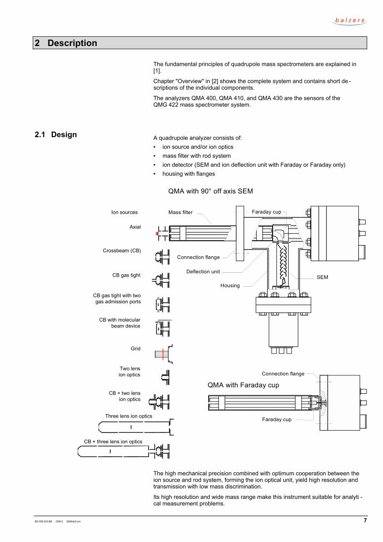
A quadrupole analyzer consists of:• = ion source and/or ion optics• = mass filter with rod system• = ion detector (SEM and ion deflection unit with Faraday or Faraday only)• = housing with flanges
Axial
Crossbeam (CB)
CB gas tight
CB gas tight with twogas admission ports
CB with molecularbeam device
Grid
Two lension optics
CB + two lension optics
Three lens ion optics
CB + three lens ion optics
Ion sources Mass filter
Deflection unitSEM
Housing
QMA with Faraday cup
Faraday cup
Faraday cup
Connection flange
QMA with 90° off axis SEM
Connection flange
The high mechanical precision combined with optimum cooperation between theion source and rod system, forming the ion optical unit, yield high resolution andtransmission with low mass discrimination.
Its high resolution and wide mass range make this instrument suitable for analyti -cal measurement problems.
2.1 Design
8 BG 800 453 BE (0001) QMA4x0.om
The various designs, with Faraday cup or with 90° off-axis SEM plus Faraday cup,as well as the ample choice of ion sources and ion optics ensure an optimumadaptation to the individual measurement problem.
The open design and low degassing rate of the analyzers, conceived as immers -ing systems, allow exact partial pressures analyses from the high vacuum up tothe extreme ultra high vacuum range.
The ionization is achieved by electron impact. Electrons are thermally emitted by acathode and focused by electrical extraction fields so that they reach the ionizationarea.
The ionization process is crucial for the overall quality of the analysis. Errorsoccurring in this part of the process are virtually irreversibly. Therefore, the ionsource must be selected very carefully.
For more details on the individual ion source types: → 33 ff.
Closed (gas tight) ion sources allow gas analyses with a minimum contributionfrom the residual vacuum. They are virtually fractionation-free, have a high signalto noise ratio, a low gas consumption, and a small time constant.
Ion optics are used for focusing ions which are generated independently of theQMA (e.g. plasma technology, laser, SIMS, thermal desorbed ions) to the massfilter.
The proper material selection and very precise manufacturing methods ensure ahigh measure of linearity and reproducibility.
QMA 430: For masses up to 300 amu the economic 8 mm rod system made ofstainless steel can be used.
QMA 400: For higher mass ranges as well as optimum stability and reproduci -bility, 8 mm molybdenum rods are used because of the superior elec -trical and thermal properties of the material.
QMA 410: The 16 mm molybdenum rod system is used for this analyzer.At constant frequency, the transmission increases as a function of therod diameter while the mass range narrows. In parallel, the impact ofthe filtered ions on the rod surfaces and thus the contamination of therod system is reduced.
The secondary ion multiplier with its 17 discrete stages and focusing dynodegeometry is a fast ion current amplifier between the quadrupole filter and thepreamplifier.
The high gain permits operation of the succeeding electrometer amplifier with alower gain setting, which results in shorter time constants and thus facilitates theobservation of rapid variations of the ion current.
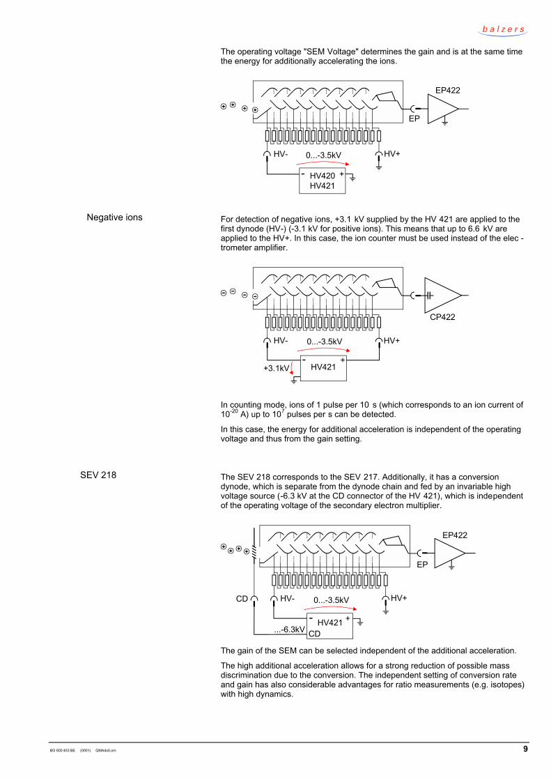
Positive ions are detected in normal operation with a negative high voltage appliedto HV- and ground connected to HV+ of the secondary electron multiplierSEV 217.
2.1.1 Ion sources
2.1.2 Mass filter
2.1.3 Secondary electronmultiplier
SEV 217
BG 800 453 BE (0001) QMA4x0.om 9
The operating voltage "SEM Voltage" determines the gain and is at the same timethe energy for additionally accelerating the ions.
HV- HV+
EP
HV420HV421
- +
0...-3.5kV
EP422
For detection of negative ions, +3.1 kV supplied by the HV 421 are applied to thefirst dynode (HV-) (-3.1 kV for positive ions). This means that up to 6.6 kV areapplied to the HV+. In this case, the ion counter must be used instead of the elec -trometer amplifier.
HV- HV+
CP422
+3.1kV HV421- +
0...-3.5kV
In counting mode, ions of 1 pulse per 10 s (which corresponds to an ion current of10-20 A) up to 107 pulses per s can be detected.
In this case, the energy for additional acceleration is independent of the operatingvoltage and thus from the gain setting.
The SEV 218 corresponds to the SEV 217. Additionally, it has a conversiondynode, which is separate from the dynode chain and fed by an invariable highvoltage source (-6.3 kV at the CD connector of the HV 421), which is independentof the operating voltage of the secondary electron multiplier.
HV- HV+
EP
CD
...-6.3kVHV421- +
0...-3.5kV
CD
EP422
The gain of the SEM can be selected independent of the additional acceleration.
The high additional acceleration allows for a strong reduction of possible massdiscrimination due to the conversion. The independent setting of conversion rateand gain has also considerable advantages for ratio measurements (e.g. isotopes)with high dynamics.
Negative ions
SEV 218
10 BG 800 453 BE (0001) QMA4x0.om
The ion sources can be equipped with cathodes (filaments) which are best suitedfor the planned application. Certain cathode materials are not available for allsource types → [5] "Spare parts lists".
In contrast to tungsten (W), rhenium (Re) does not form any stable carbides, sinceno CO2 cycle as known with W takes place. In addition, Re is not embrittled byrecrystallization.
The vapor pressure of Re is approximately 50 times higher than that of W, and thefilament life is accordingly shorter. Getter effects may occur due to the evaporationrate.
Tungsten is used when the higher vapor pressure of Re is undesirable, when along filament life is required, or when the advantages of Re are not important tothe application.
Since yttrated iridium (YOx-Ir) does not form oxides, it is quite insensitive to airinrushes.
The emission temperature of yttrated iridium filaments is lower than that of Re andW filaments. Reactions with residual gas are weaker because the ion sourcetemperature remains low.
The contamination may be stronger when substances with a low vapor pressureare admitted.
The crossbeam ion source can be equipped with a magnet unit. This is recom -mended for applications in high mass ranges, for molecular beam detection, andin the QMA 410 for separating He and D2.
The magnet increases the electron density in that part of the volume of the ionsource, from which ions can be easily focused into the mass filter.
This results in higher sensitivity and better injection conditions. In addition, themagnet prevents the majority of the electrons from hitting critical locations of theformation area. However, the linearity (measurement signal vs. pressure) isreduced.
Analyzers with integrated collimation magnets may only be baked to 300°C.
The 90° off-axis arrangement of the secondary electron multiplier has a very lowsignal background because the electrostatic 90° deflection prevents fast or excitedneutrals and photons from hitting the SEM.
There are two deflection versions:
Normal version (axial, crossbeam, grid ion source, possibly ion optics).
The inner deflection plate is on potential V6 "Deflection", the outer deflection plateis directly connected to the Faraday cup and electrometer amplifier EP1 and isthus on ground potential. If there is no EP1 in the configuration, a shortingconnector is used.
2.2 Versions
2.2.1 Cathode materials
Rhenium
Tungsten
Yttrated iridium
2.2.2 Electron collimationmagnet
2.2.3 90° deflection
One deflection voltage
BG 800 453 BE (0001) QMA4x0.om 11
EP1
EP2
Deflection unit Faraday cup
V6Deflection
SEM
Special versions (mostly with ion optics, → enclosed diagram of the QMA).
The inner deflection plate is on potential V6 "DEFI", the outer deflection plate is onpotential V7 "DEFO". The Faraday cup is isolated from the deflection plate andconnected to the electrometer amplifier EP1.
EP1
EP2
V7DEFO
V6DEFI
Depending on the application, the deflection of this version is more efficient, asaccelerating potentials are applied to both deflection plates.
In Faraday operation, the sensitivity is slightly lower than with one deflectionvoltage because less ions reach the Faraday cup.
Faraday cup operation (QMA with Faraday or SEM types operated in Faradaymode) reduces system related conversion errors of the SEM (e.g. mass dis -crimination).
Faraday operation can also be used for error detection.
The drawback of Faraday operation is the lower sensitivity, which requires a highergain and thus limits the response speed.
Some versions (e.g. with ion optics) have an isolated design i.e. the filter housingand thus ion optics, mass filter, and deflection unit are isolated from the ground. Apotential can be applied to the filter housing in order for ions formed close to theground potential (e.g. in a plasma) to be transferred through the fringe fields withsufficient velocity.
Two deflection voltages
2.2.4 Faraday cup
2.2.5 Isolated design
12 BG 800 453 BE (0001) QMA4x0.om
These versions may have an additional SHV connector for the correspondingvoltage on the QMA• = BIAS as input• = TARGET as output for SIMS analyzers
DANGER
Caution: shock hazardThe voltages of the IS 420 and the additional voltage can be ex-tremely hazardous.Consider the technical specifications of the IS 420 (→ [2]) and useonly properly made cables.
The QMA with the vacuum annealed grid ion source has a very low degassing anddesorption rate (< 10-10 mbar l/s).
For extracting ions from a plasma, an extraction hood can beinstalled.
As the versions with extraction hood are customized, a cor -responding description is enclosed with the test protocol.
Further information → [4]
For detecting ions which are not focused in the axis of theanalyzer, a beam deflection device is installed. It is based ona sector field and can be combined with an extraction hood.There is a variety of possible detection angles.
As the versions with beam deflection device are customized,a corresponding description is enclosed with the test proto -col.
If the pressure of the gas or plasma to be analyzed exceeds the admissiblemaximum pressure of the QMA, the analyzer is differentially pumped with a turbo -molecular pump.
Turbomolecularpump
The T-piece of the housing is replaced with a crosspiece. Diaphragm glandshaving a much smaller conductance than the orifice are used as seals.
The pressure drops because of the limited conductance at the entrance orifice, theextraction hood, or the beam deflection device.
The pressure range can be further increased with a dual-stage differential pumpsystem.
2.2.6 Vacuum annealed QMA
2.2.7 Extraction hood
2.2.8 Beam deflection device
2.2.9 Differential pumping
BG 800 453 BE (0001) QMA4x0.om 13
3 Technical data
Maximum admissible overpressure 2 bar (absolute)
Maximum operating pressurewith Faradaywith SEM
1×10⁻⁴ mbar1×10-5 mbar
Smallest detectable partial pressurewith Faradaywith 90° off-axis SEM and ioncounter electronics
< 10-11 mbar< 10-15 mbar
Sensitivity for airwith Faradaywith SEM
> 3×10⁻⁴ A/mbar> 200 A/mbar
Applies to QMA 400 without SEM, crossbeam ion source with magnet, emiss ion1 mA, ∆M10 = 1 u 1Refer to the Test protocol for your individual configuration.
QMA 400 QMA 410 QMA 430Rod diameterRod lengthRod material
ø 8 mm200 mmmolybdenum
ø 16 mm300 mmmolybdenum
ø 8 mm200 mmst. steel
Gain (new)Operating voltageBias voltageNumber of stagesVoltage dividerMax. admissible output voltageMax. bakeout temperatureof dynode material
> 108 at 3.5 kV1 ... 3.5 kVmax. ±3.2 kV at SEV–1718 MΩ10-5 A400 °CCu-Be
As SEV 217, however, with separateconversion dynode CDCD voltage max. – 6.3 kV
QMA 400 DN 63 CFQMA 410 DN 100 CFQMA 430 DN 63 CF
without cables and connector plateswith electron collimation magnetwith cables and connector plateswith preamplifier or electrometer
max. 400 °Cmax. 300° Cmax. 180 °Cmax. 50 °C
Stainless steel, Mo, Al2O3, Cu-Be, Ni, W, Re, yttrated iridium
Rhenium > 2,000 h
Tungsten … 10,000 h
Yttrated iridium > 10,000 h
Valid for p < 10-5 mbar, emission 1 mA and electron energy „ 70 eV in a nonoxidizing atmosphere
→ 56 Declaration of conformity
1 Peak width = 1 u on 10% of peak height
Overpressure
Vacuum
Sensitivity
Mass filter
SEV 217
SEV 218
Connection flange
Bakeout temperatures
Materials in vacuum
Filament life
Standards
14 BG 800 453 BE (0001) QMA4x0.om
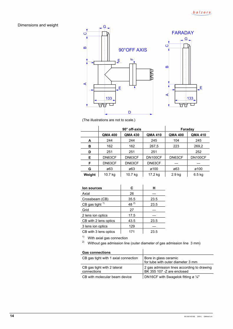
FARADAY
90°OFF AXIS
AB
C
D
E
FE
133
G
133
AB
C
E
G
(The illustrations are not to scale.)
90° off-axis FaradayQMA 400 QMA 430 QMA 410 QMA 400 QMA 410
A 244 244 245 104 245B 162 162 267,5 223 269,2D 251 251 251 252E DN63CF DN63CF DN100CF DN63CF DN100CFF DN63CF DN63CF DN63CF --- ---G ø63 ø63 ø100 ø63 ø100
Weight 10.7 kg 10.7 kg 17.2 kg 2.9 kg 6.5 kg
Ion sources C HAxial 26 ---Crossbeam (CB) 35.5 23.5CB gas tight 1) 48 2) 23.5Grid 27 ---2 lens ion optics 17.5 ---CB with 2 lens optics 43.5 23.53 lens ion optics 129 ---CB with 3 lens optics 171 23.51) With axial gas connection2) Without gas admission line (outer diameter of gas admission line 3 mm)
Gas connectionsCB gas tight with 1 axial connection Bore in glass ceramic
for tube with outer diameter 3 mmCB gas tight with 2 lateralconnections
2 gas admission lines according to drawingBK 355 107 -Z are enclosed
CB with molecular beam device DN16CF with Swagelok fitting ø ¼"
Dimensions and weight
BG 800 453 BE (0001) QMA4x0.om 15
4 Installation
DANGER
Caution: hazardous electrical voltagesHazardous voltages up to 600 V are applied to the QMA.Make sure the QMA, the vacuum chamber, and the whole system arealways correctly connected to ground.If accidental contact to the QMA is possible when the vacuum systemis opened, additional protective measures have to be taken, forinstance:• = Mechanical protection against accidental contact• = Forced disconnection of the QMS 422 from the mains power
source through door contact.
DANGER
Caution: hazardous electrical voltagesUnder unfavorable conditions (arcs, plasma, vacuum problems),voltages up to 600 V can be fed to other equipment in the vacuumchamber (e.g. gauges).If there is a possibility that such pieces of equipment become sourcesof shock hazard (consider also the conductors and connected equip -ment!) they must be arranged or protected in such a way that any riskof accidental contact, arcs, or flow of charged particles is excluded.
DANGER
Caution: hazardous external voltagesUnder unfavorable conditions (arcs, plasma, vacuum problems),voltages of other equipment installed in the vacuum system (e.g. ioni -zation gauges, plasma sources, electron beam evaporators etc.) canbe supplied to the QMA. Open connectors, connected equipment andcables are potential sources of shock hazard.If there are such potential sources of shock hazard in the vacuumsystem, protective measures have to be taken (layout, grounding,shielding etc.) to prevent such influences.The QMS 422 must also be permanently connected to ground (not viaa connector). The contact is inside, behind the mains plug. Make agrounding conductor of yellow/green stranded copper wire if neces -sary:• = 2.5 mm2 if mechanically protected (according to
DIN VDE 110 T540)• = 4.0 mm2 if not mechanically protectedConsider the specific standards of your system.
In most cases, the mounting orientation can be chosen irrespective of the function.Select the mounting orientation which is best suited to the arrangement of theradio frequency generator, QMH and cables (→ [3]).
The position of the ion source should be selected according to the requirements ofthe analytical task. For instance, reliable residual gas analysis is not possible if theanalyzer is connected to the measuring chamber only via a tube with a small dia -meter.
4.1 Preparation
Mounting orientation
16 BG 800 453 BE (0001) QMA4x0.om
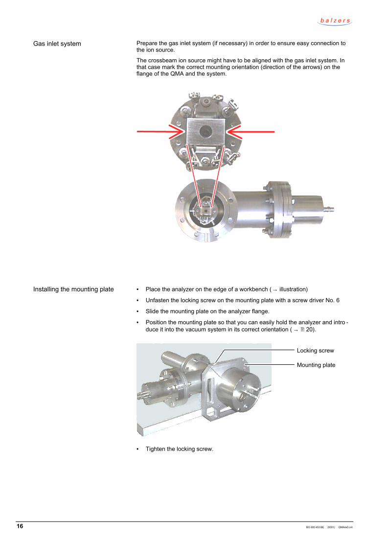
Prepare the gas inlet system (if necessary) in order to ensure easy connection tothe ion source.
The crossbeam ion source might have to be aligned with the gas inlet system. Inthat case mark the correct mounting orientation (direction of the arrows) on theflange of the QMA and the system.
• = Place the analyzer on the edge of a workbench (→ illustration)
• = Unfasten the locking screw on the mounting plate with a screw driver No. 6
• = Slide the mounting plate on the analyzer flange.
• = Position the mounting plate so that you can easily hold the analyzer and intro -duce it into the vacuum system in its correct orientation ( → 20).
Locking screw
Mounting plate
• = Tighten the locking screw.
Gas inlet system
Installing the mounting plate
BG 800 453 BE (0001) QMA4x0.om 17
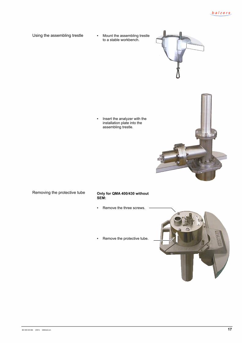
• = Mount the assembling trestleto a stable workbench.
• = Insert the analyzer with theinstallation plate into theassembling trestle.
Only for QMA 400/430 withoutSEM:
• = Remove the three screws.
• = Remove the protective tube.
Using the assembling trestle
Removing the protective tube
18 BG 800 453 BE (0001) QMA4x0.om
Note
Caution: dirt sensitive areaDirt distorts the measurement results.Always wear clean, lint-free gloves and use clean tools when workingin this area.
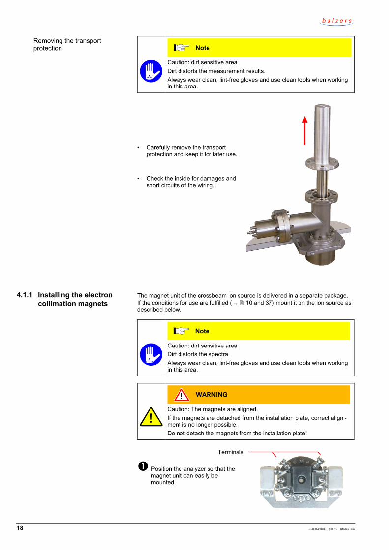
• = Carefully remove the transportprotection and keep it for later use.
• = Check the inside for damages andshort circuits of the wiring.
The magnet unit of the crossbeam ion source is delivered in a separate package.If the conditions for use are fulfilled (→ 10 and 37) mount it on the ion source asdescribed below.
Note
Caution: dirt sensitive areaDirt distorts the spectra.Always wear clean, lint-free gloves and use clean tools when workingin this area.
WARNING
Caution: The magnets are aligned.If the magnets are detached from the installation plate, correct align -ment is no longer possible.Do not detach the magnets from the installation plate!
Terminals
Position the analyzer so that themagnet unit can easily bemounted.
Removing the transportprotection
4.1.1 Installing the electroncollimation magnets
BG 800 453 BE (0001) QMA4x0.om 19
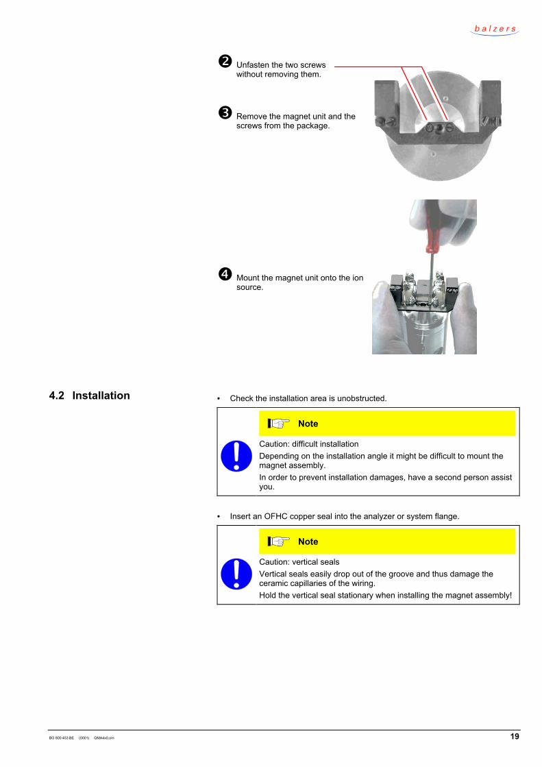
Unfasten the two screwswithout removing them.
Remove the magnet unit and thescrews from the package.
Mount the magnet unit onto the ionsource.
• = Check the installation area is unobstructed.
Note
Caution: difficult installationDepending on the installation angle it might be difficult to mount themagnet assembly.In order to prevent installation damages, have a second person assistyou.
• = Insert an OFHC copper seal into the analyzer or system flange.
Note
Caution: vertical sealsVertical seals easily drop out of the groove and thus damage theceramic capillaries of the wiring.Hold the vertical seal stationary when installing the magnet assembly!
4.2 Installation
20 BG 800 453 BE (0001) QMA4x0.om
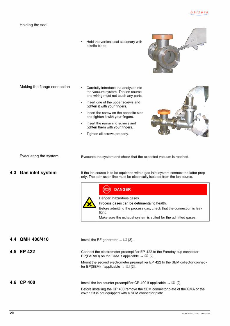
• = Hold the vertical seal stationary witha knife blade.
• = Carefully introduce the analyzer intothe vacuum system. The ion sourceand wiring must not touch any parts.
• = Insert one of the upper screws andtighten it with your fingers.
• = Insert the screw on the opposite sideand tighten it with your fingers.
• = Insert the remaining screws andtighten them with your fingers.
• = Tighten all screws properly.
Evacuate the system and check that the expected vacuum is reached.
If the ion source is to be equipped with a gas inlet system connect the latter prop -erly. The admission line must be electrically isolated from the ion source.
DANGER
Danger: hazardous gasesProcess gases can be detrimental to health.Before admitting the process gas, check that the connection is leaktight.Make sure the exhaust system is suited for the admitted gases.
Install the RF generator → [3].
Connect the electrometer preamplifier EP 422 to the Faraday cup connectorEP(FARAD) on the QMA if applicable → [2].
Mount the second electrometer preamplifier EP 422 to the SEM collector connec-tor EP(SEM) if applicable → [2].
Install the ion counter preamplifier CP 400 if applicable → [2].
Before installing the CP 400 remove the SEM connector plate of the QMA or thecover if it is not equipped with a SEM connector plate.
Holding the seal
Making the flange connection
Evacuating the system
4.3 Gas inlet system
4.4 QMH 400/410
4.5 EP 422
4.6 CP 400
BG 800 453 BE (0001) QMA4x0.om 21
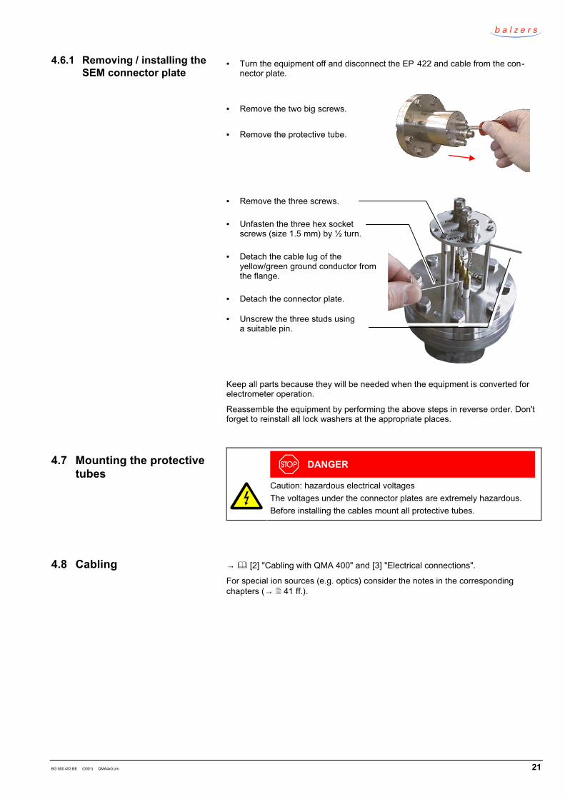
• = Turn the equipment off and disconnect the EP 422 and cable from the con-nector plate.
• = Remove the two big screws.
• = Remove the protective tube.
• = Remove the three screws.
• = Unfasten the three hex socketscrews (size 1.5 mm) by ½ turn.
• = Detach the cable lug of theyellow/green ground conductor fromthe flange.
• = Detach the connector plate.
• = Unscrew the three studs usinga suitable pin.
Keep all parts because they will be needed when the equipment is converted forelectrometer operation.
Reassemble the equipment by performing the above steps in reverse order. Don'tforget to reinstall all lock washers at the appropriate places.
DANGER
Caution: hazardous electrical voltagesThe voltages under the connector plates are extremely hazardous.Before installing the cables mount all protective tubes.
→ [2] "Cabling with QMA 400" and [3] "Electrical connections".
For special ion sources (e.g. optics) consider the notes in the correspondingchapters (→ 41 ff.).
4.6.1 Removing / installing theSEM connector plate
4.7 Mounting the protectivetubes
4.8 Cabling

22 BG 800 453 BE (0001) QMA4x0.om
Notes
BG 800 453 BE (0001) QMA4x0.om 23
5 Operation
• = Before switching the equipment on check that all components are correctlyinstalled and wired.
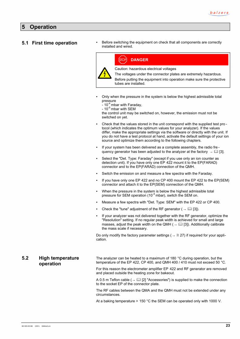
DANGER
Caution: hazardous electrical voltagesThe voltages under the connector plates are extremely hazardous.Before putting the equipment into operation make sure the protectivetubes are installed.
• = Only when the pressure in the system is below the highest admissible totalpressure- 10-4 mbar with Faraday,- 10-5 mbar with SEMthe control unit may be switched on, however, the emission must not beswitched on yet.
• = Check that the values stored in the unit correspond with the supplied test pro -tocol (which indicates the optimum values for your analyzer). If the valuesdiffer, make the appropriate settings via the software or directly with the unit. Ifyou do not have a test protocol at hand, activate the default settings of your ionsource and optimize them according to the following chapters.
• = If your system has been delivered as a complete assembly, the radio fre -quency generator has been adjusted to the analyzer at the factory → [3].
• = Select the "Det. Type: Faraday" (except if you use only an ion counter asdetection unit). If you have only one EP 422 mount it to the EP(FARAD)connector and to the EP(FARAD) connection of the QMH.
• = Switch the emission on and measure a few spectra with the Faraday.
• = If you have only one EP 422 and no CP 400 mount the EP 422 to the EP(SEM)connector and attach it to the EP(SEM) connection of the QMH.
• = When the pressure in the system is below the highest admissible totalpressure for SEM operation (10-4 mbar), switch the SEM on.
• = Measure a few spectra with "Det. Type: SEM" with the EP 422 or CP 400.
• = Check the "tune" adjustment of the RF generator (→ [3]).
• = If your analyzer was not delivered together with the RF generator, optimize the"Resolution" setting. If no regular peak width is achieved for small and largemasses, adjust the peak width on the QMH (→ [3]). Additionally calibratethe mass scale if necessary.
Do only modify the factory parameter settings (→ 27) if required for your appli-cation.
The analyzer can be heated to a maximum of 180 °C during operation, but thetemperature of the EP 422, CP 400, and QMH 400 / 410 must not exceed 50 °C.
For this reason the electrometer amplifier EP 422 and RF generator are removedand placed outside the heating zone for bakeout.
A 0.5 m Teflon cable (→ [2] "Accessories") is supplied to make the connectionto the socket EP of the connector plate.
The RF cables between the QMA and the QMH must not be extended under anycircumstances.
At a baking temperature > 150 °C the SEM can be operated only with 1000 V.
5.1 First time operation
5.2 High temperatureoperation
24 BG 800 453 BE (0001) QMA4x0.om
The analyzer can be baked at up to 400 °C.
The EP 422 and CP 400 have to be removed for that purpose (→ [2]). Theycan only be mounted when the flange has cooled down to < 50 °C.
For baking temperatures > 200 °C remove the connector plates as follows:
• = If you have a 90° SEM, remove the connector plate (→ 21), however, leavethe three studs in place.
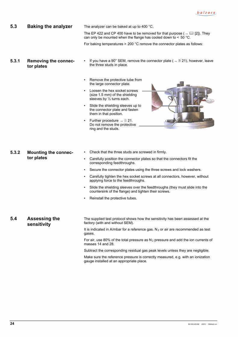
• = Remove the protective tube fromthe large connector plate.
• = Loosen the hex socket screws(size 1.5 mm) of the shieldingsleeves by ½ turns each.
• = Slide the shielding sleeves up tothe connector plate and fastenthem in that position.
• = Further procedure → 21.Do not remove the protectivering and the studs.
• = Check that the three studs are screwed in firmly.
• = Carefully position the connector plates so that the connectors fit thecorresponding feedthroughs.
• = Secure the connector plates using the three screws and lock washers.
• = Carefully tighten the hex socket screws at all connectors, however, withoutapplying force to the feedthroughs.
• = Slide the shielding sleeves over the feedthroughs (they must slide into thecountersink of the flange) and tighten their screws.
• = Reinstall the protective tubes.
The supplied test protocol shows how the sensitivity has been assessed at thefactory (with and without SEM).
It is indicated in A/mbar for a reference gas. N 2 or air are recommended as testgases.
For air, use 80% of the total pressure as N 2 pressure and add the ion currents ofmasses 14 and 28.
Subtract the corresponding residual gas peak levels unless they are negligible.
Make sure the reference pressure is correctly measured, e.g. with an ionizationgauge installed at an appropriate place.
5.3 Baking the analyzer
5.3.1 Removing the connec-tor plates
5.3.2 Mounting the connec-tor plates
5.4 Assessing thesensitivity
BG 800 453 BE (0001) QMA4x0.om 25
The gain and thus the sensitivity can be roughly adjusted with the SEM highvoltage "SEM Volt". Avoid values below 1 kV as well as ion currents > 1 µA formore than a few minutes, as in these ranges the gain is not stable.
When the gas composition is unfavorable (hydrocarbons and other organicvapors), prevent contamination of the SEM by operating it a with a low current.
Operate the equipment in Faraday mode, if that makes sense for your application.
At very low partial pressures (very small peaks) the ion current consists of singlepulses. At a very high SEM gain setting, these pulses can overmodulate the stageof the electrometer preamplifier and thus cause measurement errors (e.g. non -linearity) which are not obvious.
Considerable deviations (> 10 %) of the values measured within various electro-meter ranges, discontinuities of the measured value curves in autorange mode,flattened peaks, incorrect isotope ratios etc. may be due to this effect.
In such cases, reduce the "SEM Volt.", select a less sensitive "Range" or use"Range-L" to lock the most sensitive measurement ranges.
With the ion counter, this problem does usually not occur.
Register the range to be considered of the mass spectrum in SEM and Faradaymode. The ratio of the currents of two corresponding peaks is the gain with thecurrent operation settings.
With this method, the influence of the 90° ion deflection device is taken into con -sideration.
Due to electron impacts on the ion source surfaces, adsorbed contaminants aredesorbed as so-called EID ions, which are represented in the spectrum, e.g. withmasses 16 (O+), 19 (F+), 23 (Na+), 35/37 (Cl+) and 39/41 (K+).
EID ions appear especially under UHV conditions. They can be reduced by de -gassing (Degas or temporary operation with high emission).
In order to distinguish between EID ions and ions from the volume, reduce the fieldaxis voltage "Field Axis". The peak level of normal ions is thus strongly reducedwhereas the peak level of EID ions is less affected as they are formed on thehighest potential.
Therefore, to prevent suppression of the normal ions, do not select a too low"Field Axis" value
Degas is chiefly intended for UHV measurements (with a grid ion source). Degasmust not be activated at pressures > 10-7 mbar as otherwise, the ion source willbe contaminated.
Consider the specifications of the individual ion sources ( → 33 ff.).
Optimize the filament protection "Protect" for the degas mode.
To lock the degas mode, set "Protect" to 0 A.
5.5 Secondary electronmultiplier SEM
5.5.1 Contamination
5.5.2 Low partial pressures
5.5.3 Gain factor
5.6 Surface ions
5.7 Degas

26 BG 800 453 BE (0001) QMA4x0.om
Notes
BG 800 453 BE (0001) QMA4x0.om 27
6 Optimization
For certain applications the factory settings should be modified. The followingsections explain how to determine the optimum parameter values.
With increasing contamination or after revision work, the settings should bemodified according to the following sections.
The potentials and their denominations are listed in [2], "Technical Data".
It should be possible to measure a spectrum with the default values of the equip -ment (→ [2] Appendix A) – except for the "SPEC(ial)" ion source type. Thevalues should always be optimized for the analyzer used.
The objective of the ion source parameters is to achieve a high sensitivity, a goodpeak shape, and a low mass discrimination. Possibly, other conditions should befulfilled, too (see below).
This chapter applies to virtually all ion sources; certain potentials are not neededfor all ion sources.
Please refer to the information on the individual ion sources ( → 33 ff.).
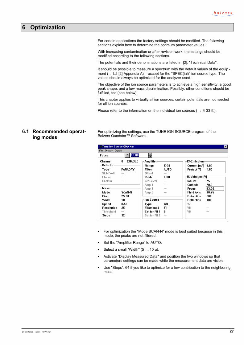
For optimizing the settings, use the TUNE ION SOURCE program of theBalzers Quadstar™ Software.
• = For optimization the "Mode SCAN-N" mode is best suited because in thismode, the peaks are not filtered.
• = Set the "Amplifier Range" to AUTO.
• = Select a small "Width" (5 ... 10 u).
• = Activate "Display Measured Data" and position the two windows so thatparameters settings can be made while the measurement data are visible.
• = Use "Steps": 64 if you like to optimize for a low contribution to the neighboringmass.
6.1 Recommended operat-ing modes
28 BG 800 453 BE (0001) QMA4x0.om
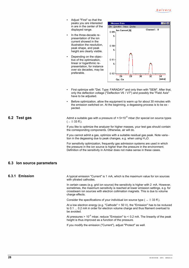
• = Adjust "First" so that thepeaks you are interestedin are in the center of thedisplayed range.
• = In the three-decade re-presentation of the ioncurrent showed in theillustration the resolution,peak shape, and peakheight are clearly visible.
• = Depending on the objec-tive of the optimization,linear or logarithmic re-presentation, for instanceover six decades, may bepreferable.
• = First optimize with "Det. Type: FARADAY" and only then with "SEM". After that,only the deflection voltage ("Deflection V6 / V7") and possibly the "Field Axis"have to be adjusted.
• = Before optimization, allow the equipment to warm up for about 30 minutes withthe emission switched on. At the beginning, a degassing process is to be ex -pected.
Admit a suitable gas with a pressure of … 5×10⁻⁶ mbar (for special ion source types(→ 33 ff.).
If you like to optimize the analyzer for higher masses, your test gas should containthe corresponding components. Otherwise, air will do.
If you cannot admit a gas, optimize with a suitable residual gas peak. Note varia -tion in the degassing due to peak changes, e.g. when using H 2O.
For sensitivity optimization, frequently gas admission systems are used in whichthe pressure in the ion source is higher than the pressure in the environment.Definition of the sensitivity in A/mbar does not make sense in these cases.
A typical emission "Current" is 1 mA, which is the maximum value for ion sourceswith yttrated cathodes.
In certain cases (e.g. grid ion source) the sensitivity is higher with 2 mA. However,sometimes, the maximum sensitivity is reached at lower emission settings, e.g. forcrossbeam ion sources with electron collimation magnets. This is due to volumecharge effects.
Consider the specifications of your individual ion source type ( → 33 ff.).
At a low electron energy (e.g. "Cathode" < 50 V), the "Emission" has to be reducedto 0.1 ... 0.2 mA in order for electron volume charge and thus filament overload tobe avoided.
At pressures > 10-5 mbar, reduce "Emission" to < 0.2 mA. The linearity of the peakheight is thus improved as a function of the pressure.
If you modify the emission ("Current"), adjust "Protect" as well.
6.2 Test gas
6.3 Ion source parameters
6.3.1 Emission
BG 800 453 BE (0001) QMA4x0.om 29
When the pressure in the ion source rises, the heating current of the filamentrises, too. This effect is used to turn the cathode off when the pressure rises.
"Protect" defines the switching off threshold. To achieve optimum protection setthe threshold as low as possible. The setting is optimal if you can just switch onthe emission without triggering the protection (→ [2] "Filament protection").
If it is not possible to turn on the emission, the "Protect" threshold setting might betoo low.
"IonRef" is the nominal potential on which the ions are formed. The actually effec -tive potential is somewhat lower because of the penetration coefficient of the ex -traction field and the electron volume charge.
"IonRef" is the reference potential for all other potentials ( → [2] "Technical Data").
In general, the "IonRef" should be set slightly higher (approx. 20 V) than the elec-tron energy ("V2 Cathode"). The cathode is thus on a positive potential with regardto ground so that no electrons are emitted to the environment. This prevents in -terferences with the Faraday cup of the system and nearby measurement equip -ment (e.g. ionization manometer). Moreover, gases adsorbed in the environmentcould be emitted through electron impact, which could influence the measurement.
At lower electron energies (e.g. 40 V), less double charged ions are formed. Thisprevents for instance contribution of 36Ar++ to mass 18, which would complicate thedetection of water vapor traces in argon.
The following effects of the "IonRef" setting are also influenced by the mechanictolerances, e.g. of the exact cathode position:
• = At low values (25 ... 40 V) the sensitivity for lower masses is higher, whereasthe maximum sensitivity for higher masses is reached with higher values.
• = The higher the "IonRef" setting the lower the mass discrimination, i.e. the sen -sitivity decreases with higher mass numbers.
• = These relationships become even clearer with higher mass ranges and smallerfilter dimensions.
• = If you like to minimize the mass discrimination, select a peak with the highestpossible mass for optimizing the ion source parameters.
For the ion optics select an "IonRef" value which is slightly lower than the energyof the (positive) ions to be detected.
The cathode voltage determines the acceleration voltage of the electrons and thusthe nominal ionization energy. The actual ionization energy deviates slightly fromthat value, inter alia due to the extraction field. Calibration measurements are re -quired for applications for which the exact ionization energy has to be known.
The reference data in spectra libraries are usually referenced to 70 eV.
At lower V2 values, there are less dissociation peaks and multiply ionized peaks(e.g. Ar++, N+).
Note
Caution: filament overloadAt a reduced ionization energy ("Cathode" e.g. 40 eV) the cathodetemperature required for the emission rises and the filament couldthus burn out.In that event reduce the emission to e.g. 0.1 mA and adjust "Protect"→ [2] "Filament protection".
6.3.2 Protection
6.3.3 V1 IonRef
6.3.4 V2 Cathode
30 BG 800 453 BE (0001) QMA4x0.om
Adjust "Focus" to the maximum peak level.
If there are several maxima, select the one with the lowest voltage value whileconsidering the information which applies to your ion source ( → 33 ff.).
When "Focus" is modified "Extraction" must be optimized accordingly (if appli -cable).
The field axis voltage ("V4-Field Axis") is the potential in the axis of the quadrupolefield. It acts as decelerating voltage for the ions to remain in the rod system longenough to be resolved.
The field axis voltage is the nominal energy 2 Enom of the ions in the rod system.
The optimum value of "Field Axis" depends inter alia on the frequency (QMH Type)and the QMA type. Lower frequencies (higher mass ranges) or shorter rod sys -tems require lower ion energies because the ions must stay longer in the massfilter to be resolved.
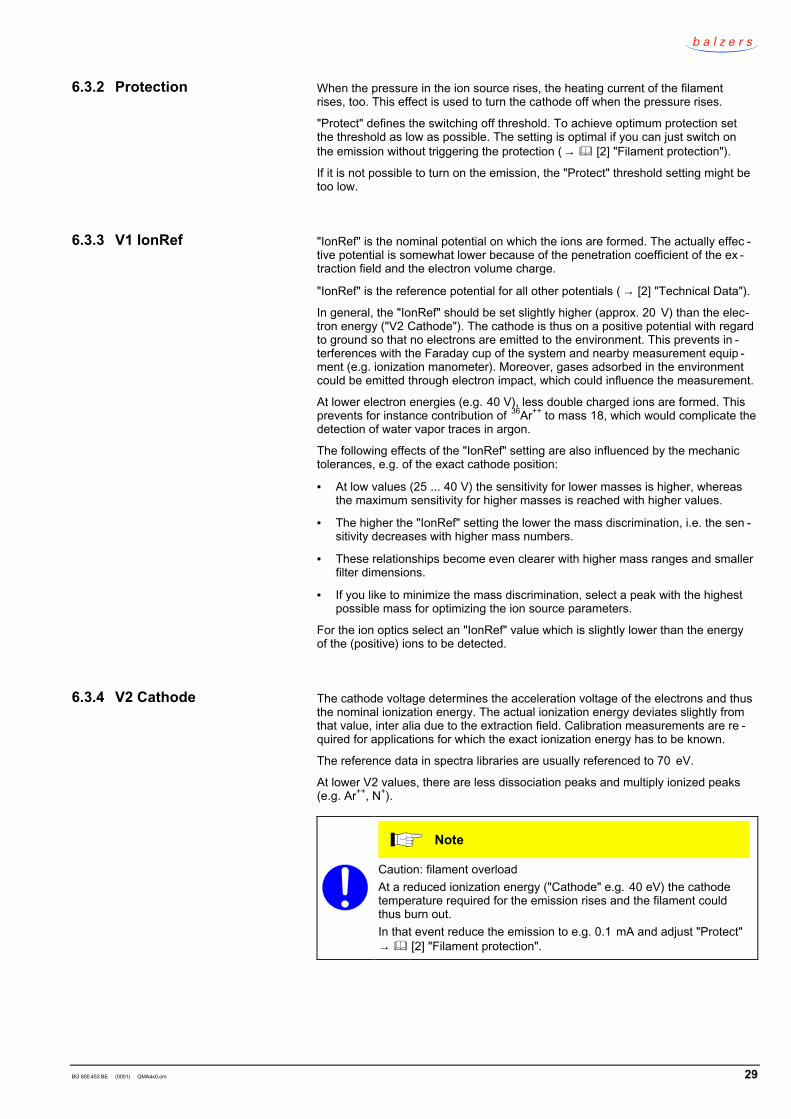
The higher the value, the higher the peaks. However, the resolution is lower andthe peak shape deteriorated.
Exceedingly high"Field Axis" values result in"frayed" peaks.
If with "Resolution" theresolution is not improvedand the peak level isdecreased, lower the"Field Axis" value.
The combined optimization of "Field Axis" and "Resolution" should result in amaximum peak level with the desired resolution and a sufficiently good peakshape.
If an insufficient peak shape cannot be improved by reducing the "Field Axis"value, there may be contamination or mechanical problems (e.g. ion source notcorrectly centered or tilted).
Chapter "Surface ions" (→ 25) shows how to distinguish between normal andso-called EID ions by means of "Field Axis".
The extraction voltage ("V5-Extraction") accelerates the ions from the ionizationarea towards the rod system. If the extraction voltage is modified, "Focus" mustalso be optimized.
The potential V8 is used for special cases (e.g. in combination with certain optics).
The Wehnelt voltage is only used for the axial ion source ( → 33).
2 The actual value of the ion energy Eeff is slightly lower. For calculating the
deviation, reduce the "Field Axis" value until the measured peak justdisappears (i.e. decreases to <1%). You thus obtain the value E o.
Eeff = Enom – Eo
6.3.5 V3 Focus
6.3.6 V4 Field Axis
6.3.7 V5 Extraction
6.3.8 V8 Reserve
6.3.9 V9 Wehnelt
BG 800 453 BE (0001) QMA4x0.om 31
Die deflection voltages ("Deflection", "DEFI" and "DEFO") direct the ions throughthe 90° deflection condensator.
In the QMG 422, in Faraday operation, they are automatically switched to groundpotential.
The polarity of the two potentials is opposite to the ion polarity. The ions areaccelerated from the mass filter to the deflection unit and directed to the SEM.
There are two deflection versions (→ 10):
The inner deflection plate is on potential "V6 Deflection", outer is directly con -nected to the Faraday cup and the electrometer amplifier EP1 and is thus onground potential.
The optimum value is determined by the ion formation potential "IonRef" and to acertain extent by the SEM voltage.
Approximate values: IonRef 120 V 40 VDeflection 300 V 200 V
Adjust "Deflection" so that a normal peak level is reached.
When the "SEM Volt" is modified, the "Deflection" has to be adjusted, too.
The inner deflection plate is on V6 and the outer on V7.
Alternatingly adjust "DEFI" and "DEFO" to the maximum peak level.
If the "SEM Volt" is modified, the two potentials have to be adjusted, too.
Do not select a better "Resolution" than required for the measurement task. Thewider the peaks are the better are the sensitivity and stability of the measuredvalues.
Consider the interdependence of "Field Axis" and "Resolution" (→ 30).
If the peak width is irregular over the whole mass range it can be corrected byadjusting the settings of the radio frequency generator QMH (→ [3]).
The resolution and peak shape might be improved by interchanging the RF cablesat the analyzer. Optimize with both polarities and choose the better version.
Before exchanging the RF cables, set "First" to 0 and "Mode" to "SAMPLE".
If by reversing the polarity, the sensitivity is improved or deteriorated by more than50 %, there is contamination or a mechanic fault.
6.4 V6 / V7 Deflection
One deflection voltage
Two deflection voltages
6.5 Resolution
6.6 RF cable polarity

32 BG 800 453 BE (0001) QMA4x0.om
Notes
BG 800 453 BE (0001) QMA4x0.om 33
7 Ion sources
By focusing the ions in axial direction, the axial ion source supplies ions with anarrow energy distribution and a small speed component transversely to the axisso that excellent resolution, high sensitivity, and good linearity are achieved.
The open design allows registration of rapid changes in the partial pressure withminimum distortion due to outgassing and surface reactions.
Standard filament material: Re. W and YO x-Ir filaments are also available.
• = General gas analyses• = Residual gas analysis
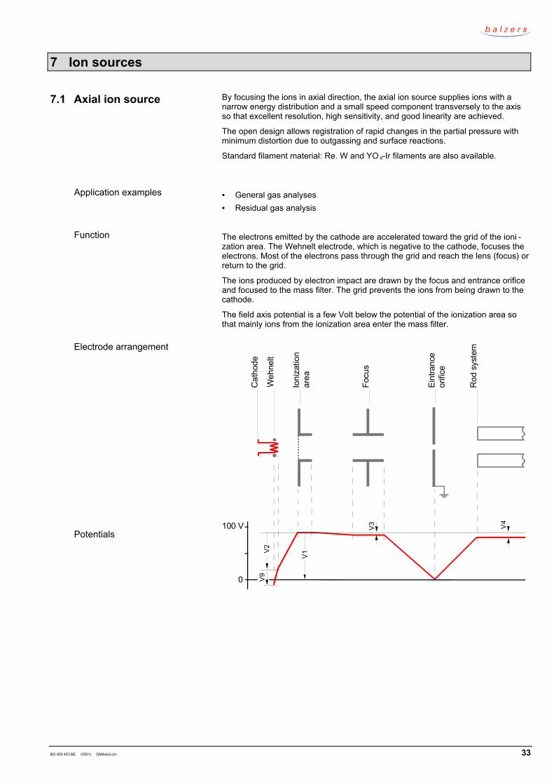
The electrons emitted by the cathode are accelerated toward the grid of the ioni -zation area. The Wehnelt electrode, which is negative to the cathode, focuses theelectrons. Most of the electrons pass through the grid and reach the lens (focus) orreturn to the grid.
The ions produced by electron impact are drawn by the focus and entrance orificeand focused to the mass filter. The grid prevents the ions from being drawn to thecathode.
The field axis potential is a few Volt below the potential of the ionization area sothat mainly ions from the ionization area enter the mass filter.
100 V
0
V1
V3
V2
V4
V9W
ehne
lt
Cat
hode
Ioni
zatio
nar
ea
Focu
s
Eint
ranc
eor
ifice
Rod
sys
tem
7.1 Axial ion source
Application examples
Function
Electrode arrangement
Potentials
34 BG 800 453 BE (0001) QMA4x0.om
Emission 1 mA 1)
V1 IonREF 90 VV2 Cathode 70 eV 2)
V3 Focus 20 VV4 Field Axis 10 V 3)
V6 Deflection 300 VV9 Wehnelt 30 V (max. 40)
Protection WYOx-Ir / Re
4.2 A3.5 A
1) At p > 5×10⁻⁶ mbar reduce to 0.1 mA.2) Before reduction of V2 to < 50 eV reduce the "Emission" to 0.1 mA and V9 to
< 20 V, in order to prevent overload of the cathode.3) 5 V at mass range 1024 or 2048
Start with the values which previously supplied good results, with the values in thetest protocol or otherwise with the values of the above table.
Adjust "Focus" to the maximum peak level.
Adjust "Wehnelt" to the maximum peak level (if "Cathode" < 50 V maximum= 20 V!).
Search the combination of "Field Axis" and "Resolution" which yields thebest peak level and shape.
Try which is the better RF cable polarity (→ 31).
With Degas, the outgassing rate of the axial ion source is reduced.
Pressure ≤ 10-8 mbarEmission ≤ 10 mA (at 550 V)Time ≤ 5 minutes
Typical values
Adjustment
Degas
BG 800 453 BE (0001) QMA4x0.om 35
The open design of the crossbeam ion source allows quick reaction to changes inthe gas composition.
The crossbeam ion source has two filaments and has a long service life.
Standard filament material: W. YO x-Ir also available.
Molecular beams can be injected through the sensitive volume perpendicularlyand parallel to the system axis.
The ionization chamber of the gas tight crossbeam ion sources is sealed.
The conductance is ≈ 1 l/s. Set the operating pressure to < 10 mbar.
The molecular beam device generates a directed gas beam from which only a fewparticles hit the ionization area. Therefore, no contamination layers are formed.
Using an electron collimation magnet is recommended.
Recommended inlet pressure: 0.5 mbar
• = Analysis of particle beams and general gas analysis.• = Qualitative and quantitative gas analyses (composition and time behavior)• = Analysis of reactive and aggressive gases (with special accessories)• = Detection of contaminants/impurities in gases• = Isotope measurements• = Residual gas analysis in vacuum processes (e.g. plasma etching)• = Process monitoring / process control (e.g. control of the gas composition or
control of evaporation sources)• = Molecular beam applications• = Analysis of not easily volatilized substances (with inlet device for solids)
Because of their minimal gas consumption, low defractionation and small timeconstant, gas tight ion sources are ideal for:
• = Measurement of gases and solvents in liquids• = Respiration analyses• = Analyses of gas mixtures• = Trace analyses with little influence of residual gases• = Analyses of corrosive or toxic gases (→ 5)
The electrons emitted by the cathode and focused by the Wehnelt electrode,which is connected to the cathode, enter the ionization area perpendicularly to thesystem axis through a gap and ionize the gas in the ionization area.
The ions are drawn out by the extraction electrode and focused into the mass filterthrough the ion lens (Focus).
The electron beam, particle beam (if a molecular beam is admitted) and ion ex -traction are arranged perpendicularly to each other.
The field axis potential, which is a few Volt below the potential of the ionizationarea mainly focuses ions from the ionization area into the mass filter.
7.2 Crossbeam ion source
Gas tight version
Molecular beam device
Application examples
Function
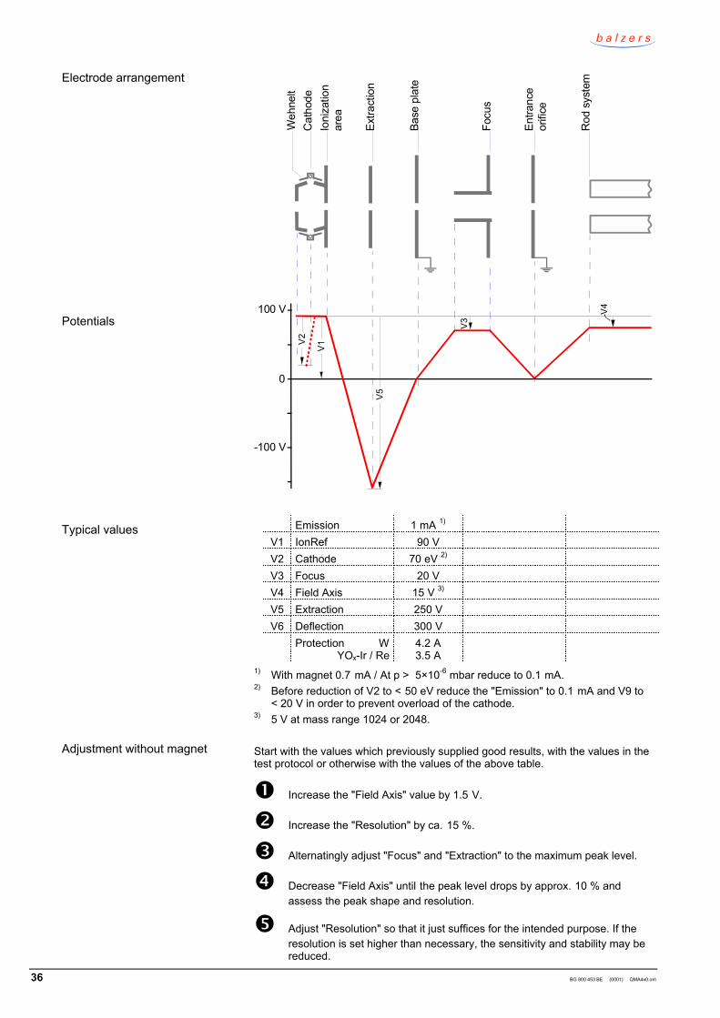
36 BG 800 453 BE (0001) QMA4x0.om
100 V
-100 V
0
V1
V5
V3
V4
V2W
ehne
ltC
atho
deIo
niza
tion
area
Extra
ctio
n
Base
pla
te
Focu
s
Entra
nce
orifi
ce
Rod
sys
tem
Emission 1 mA 1)
V1 IonRef 90 VV2 Cathode 70 eV 2)
V3 Focus 20 VV4 Field Axis 15 V 3)
V5 Extraction 250 VV6 Deflection 300 V
Protection WYOx-Ir / Re
4.2 A3.5 A
1) With magnet 0.7 mA / At p > 5×10⁻⁶ mbar reduce to 0.1 mA.2) Before reduction of V2 to < 50 eV reduce the "Emission" to 0.1 mA and V9 to
< 20 V in order to prevent overload of the cathode.3) 5 V at mass range 1024 or 2048.
Start with the values which previously supplied good results, with the values in thetest protocol or otherwise with the values of the above table.
Increase the "Field Axis" value by 1.5 V.
Increase the "Resolution" by ca. 15 %.
Alternatingly adjust "Focus" and "Extraction" to the maximum peak level.
Decrease "Field Axis" until the peak level drops by approx. 10 % andassess the peak shape and resolution.
Adjust "Resolution" so that it just suffices for the intended purpose. If theresolution is set higher than necessary, the sensitivity and stability may bereduced.
Electrode arrangement
Potentials
Typical values
Adjustment without magnet

BG 800 453 BE (0001) QMA4x0.om 37
If the peak shape is unsatisfactory (spikes, tailings), try to improve it bylowering the "Field Axis".
Try to improve the sensitivity by gradually adjusting the "IonRef" setting (insteps of 5 V). After each step, readjust the parameters. Proceed systemati -cally and record the parameters and the corresponding peak level andshape.
Repeat the procedure for the second cathode. After activating the cathode,wait until thermal stability is reached. If the sensitivity of the two cathodes isquite different, there might be mechanical deformation.
Try which is the better RF cable polarity (→ 31).
For analyses with different pressures we recommend removing the magnet unit orreducing the emission to 0.1 mA.
For low emissions (up to 0.1 mA) follow the procedure in section "Adjustmentwithout magnet".
At a higher emission and for achieving maximum sensitivity, proceed as follows tofind the best emission setting:
Set the pressure in the system to the value for which you like to optimizeyour ion source This value should remain constant for all adjustments.
Set the "Field Axis" to 16 V and "Emission" to 0.5 mA.
Alternatingly adjust "Extraction" and "Focus" several times on the highestpeak level.
Note the peak level and the corresponding values of "Emission","Extraction" and "Focus".
If the emission is < 1 mA, increase it by 0.1 mA and repeat the procedurefrom step .
In the data records, look for the point with the highest peak and make thecorresponding parameter settings.
Make the "Field Axis" and "Resolution" setting as described in section"Adjustment without magnet".
Determine which is the most favorable "IonRef" value and better cablepolarity as described in section "Adjustment without magnet".
Increase "Extraction" until the sensitivity is 5 % lower; the stability becomesthus better.
The ion source is now optimized for the current pressure. For other pressures, itusually suffices to adjust "Extraction" and "Focus".
Degassing of the crossbeam ion source is recommended only for special cases.
Pressure ≤ 10-8 mbarEmission ≤ 10 mA (at 550 V)Time ≤ 5 minutes
Adjustment with magnet
Degas

38 BG 800 453 BE (0001) QMA4x0.om
Notes
BG 800 453 BE (0001) QMA4x0.om 39
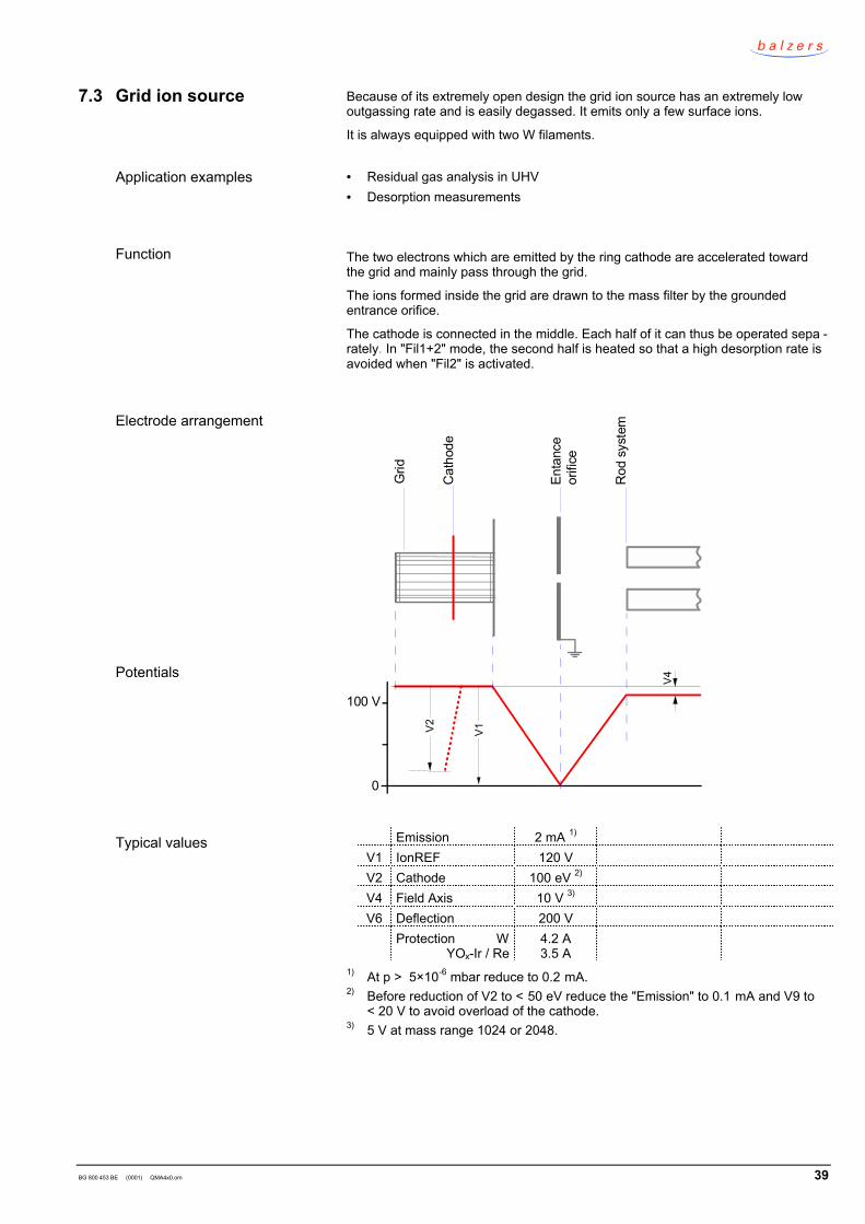
Because of its extremely open design the grid ion source has an extremely lowoutgassing rate and is easily degassed. It emits only a few surface ions.
It is always equipped with two W filaments.
• = Residual gas analysis in UHV• = Desorption measurements
The two electrons which are emitted by the ring cathode are accelerated towardthe grid and mainly pass through the grid.
The ions formed inside the grid are drawn to the mass filter by the groundedentrance orifice.
The cathode is connected in the middle. Each half of it can thus be operated sepa -rately. In "Fil1+2" mode, the second half is heated so that a high desorption rate isavoided when "Fil2" is activated.
100 V
0
V1V2
V4
Grid
Cat
hode
Enta
nce
orifi
ce
Rod
sys
tem
Emission 2 mA 1)
V1 IonREF 120 VV2 Cathode 100 eV 2)
V4 Field Axis 10 V 3)
V6 Deflection 200 VProtection W
YOx-Ir / Re4.2 A3.5 A
1) At p > 5×10⁻⁶ mbar reduce to 0.2 mA.2) Before reduction of V2 to < 50 eV reduce the "Emission" to 0.1 mA and V9 to
< 20 V to avoid overload of the cathode.3) 5 V at mass range 1024 or 2048.
7.3 Grid ion source
Application examples
Function
Electrode arrangement
Potentials
Typical values
40 BG 800 453 BE (0001) QMA4x0.om
Start with the values which previously supplied good results, with the values in thetest protocol or otherwise with the values of the above table.
Adjust "IonRef" to the maximum peak level, however, below the "Cathode"value as otherwise, electrons hit grounded components and desorb ions.
Increase "Field Axis" until the peaks "fray" (→ 30) and then reduce thatvalue again until a clear peak shape is reached.
Make the desired "Resolution" setting, ideally unit resolution ∆M10 = 1.
Repeat steps and if necessary.
Try which is the better RF cable polarity (→ 31).
With Degas the outgassing rate of the grid ion source and the desorption ofsurface ions is reduced.
Pressure ≤ 10-7 mbarEmission ≤ 20 mA (at 550 V)Time 10...15 minutes
During the degassing process, operate both filament parts (Fil1+2) to preventadsorption on the cold part.
Recommendation:• = Degas 10 ... 15 minutes• = Wait until the final pressure is reached.• = Check the spectrum.• = Repeat the procedure if necessary.
Adjustment
Degas
BG 800 453 BE (0001) QMA4x0.om 41
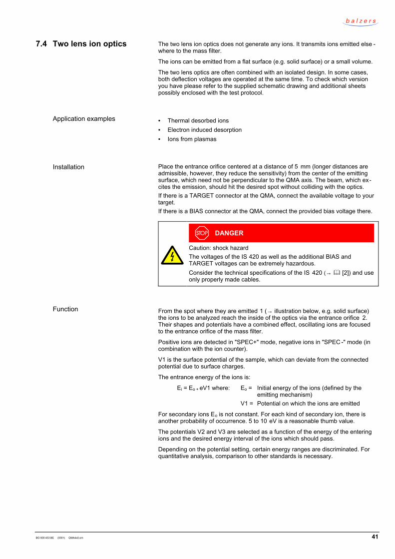
The two lens ion optics does not generate any ions. It transmits ions emitted else -where to the mass filter.
The ions can be emitted from a flat surface (e.g. solid surface) or a small volume.
The two lens optics are often combined with an isolated design. In some cases,both deflection voltages are operated at the same time. To check which versionyou have please refer to the supplied schematic drawing and additional sheetspossibly enclosed with the test protocol.
• = Thermal desorbed ions• = Electron induced desorption• = Ions from plasmas
Place the entrance orifice centered at a distance of 5 mm (longer distances areadmissible, however, they reduce the sensitivity) from the center of the emittingsurface, which need not be perpendicular to the QMA axis. The beam, which ex-cites the emission, should hit the desired spot without colliding with the optics.If there is a TARGET connector at the QMA, connect the available voltage to yourtarget.If there is a BIAS connector at the QMA, connect the provided bias voltage there.
DANGER
Caution: shock hazardThe voltages of the IS 420 as well as the additional BIAS andTARGET voltages can be extremely hazardous.Consider the technical specifications of the IS 420 (→ [2]) and useonly properly made cables.
From the spot where they are emitted 1 (→ illustration below, e.g. solid surface)the ions to be analyzed reach the inside of the optics via the entrance orifice 2.Their shapes and potentials have a combined effect, oscillating ions are focusedto the entrance orifice of the mass filter.
Positive ions are detected in "SPEC+" mode, negative ions in "SPEC -" mode (incombination with the ion counter).
V1 is the surface potential of the sample, which can deviate from the connectedpotential due to surface charges.
The entrance energy of the ions is:
Ei = Eo + eV1 where: Eo = Initial energy of the ions (defined by theemitting mechanism)
V1 = Potential on which the ions are emitted
For secondary ions Eo is not constant. For each kind of secondary ion, there isanother probability of occurrence. 5 to 10 eV is a reasonable thumb value.
The potentials V2 and V3 are selected as a function of the energy of the enteringions and the desired energy interval of the ions which should pass.
Depending on the potential setting, certain energy ranges are discriminated. Forquantitative analysis, comparison to other standards is necessary.
7.4 Two lens ion optics
Application examples
Installation
Function
42 BG 800 453 BE (0001) QMA4x0.om
50 V
0
V2
V4
2
V1
V3
Entra
nce
orifi
ce
Rod
sys
tem
Lens
1
Lens
2
Targ
et
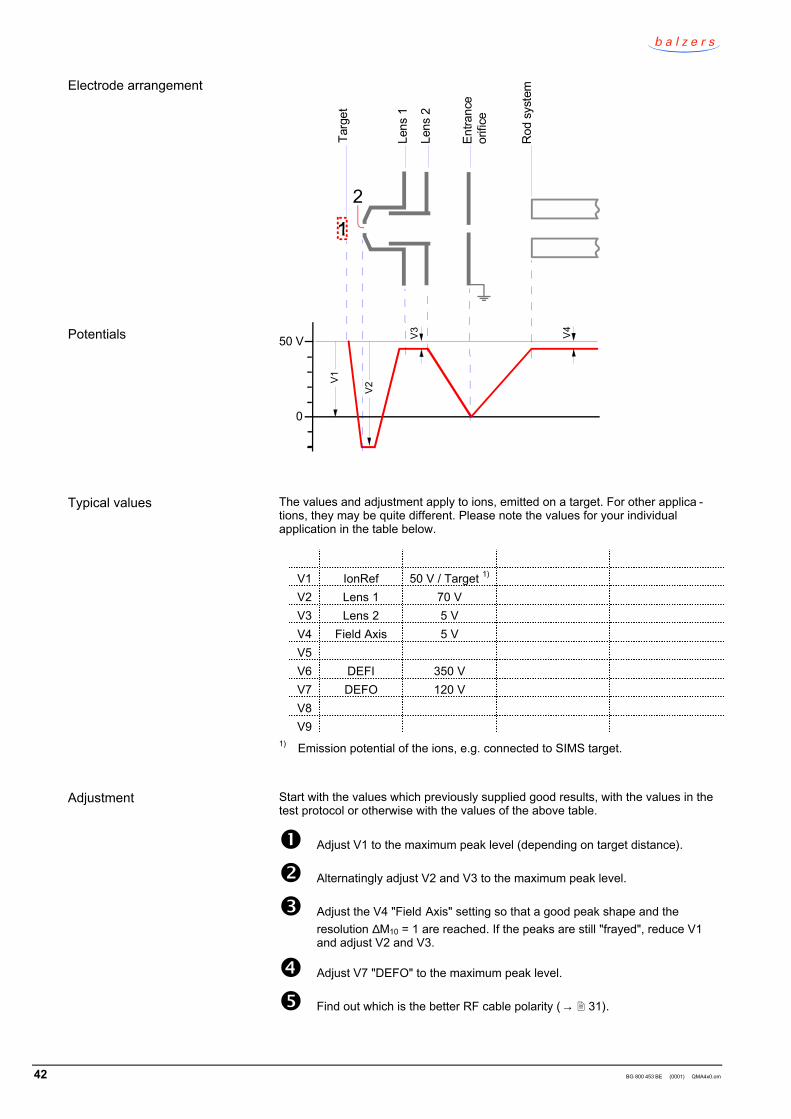
The values and adjustment apply to ions, emitted on a target. For other applica -tions, they may be quite different. Please note the values for your individualapplication in the table below.
V1 IonRef 50 V / Target 1)
V2 Lens 1 70 VV3 Lens 2 5 VV4 Field Axis 5 VV5V6 DEFI 350 VV7 DEFO 120 VV8V9
1) Emission potential of the ions, e.g. connected to SIMS target.
Start with the values which previously supplied good results, with the values in thetest protocol or otherwise with the values of the above table.
Adjust V1 to the maximum peak level (depending on target distance).
Alternatingly adjust V2 and V3 to the maximum peak level.
Adjust the V4 "Field Axis" setting so that a good peak shape and theresolution ∆M10 = 1 are reached. If the peaks are still "frayed", reduce V1and adjust V2 and V3.
Adjust V7 "DEFO" to the maximum peak level.
Find out which is the better RF cable polarity (→ 31).
Electrode arrangement
Potentials
Typical values
Adjustment
BG 800 453 BE (0001) QMA4x0.om 43
This version offers the characteristics of the two lens ion optics combined with thefeatures of the crossbeam ion source. It is used for detecting foreign ions andneutral particles ionized in the crossbeam ion source.
The crossbeam ion source with two lens ion optics is often combined with theopen design. In some cases, both deflection voltages are operated at the sametime. To check which version you have please refer to the supplied schematicdrawing and additional sheets possibly enclosed with the test protocol.
The AS 400 adapted is included in the scope of delivery.
• = Thermal desorbed ions• = Electron induced desorption• = Ions from plasmas• = Applications which require a short distance between the gas source and ioni -
zation area• = Detection of unstable (thermal incited) particles
→ 41 and 35.
The AS 400 adapter converts some potentials (see the table below) depending onwhether the equipment is operated in crossbeam or ion optics mode. The ionoptics mode is activated by selecting the ion source type "SPEC+ / SPEC-" and"Emission = Off".
Place the entrance orifice centered at a distance of 5 mm (longer distances areadmissible, however, they reduce the sensitivity) from the center of the emittingsurface, which need not be perpendicular to the QMA axis. The beam, which ex-cites the emission, should hit the desired spot without colliding with the optics.
The AS 400 adapter is incorporated in the control unit and is connected betweenthe IS 400 and the QMA (for subsequent installation → [2]).
DANGER
Caution: shock hazardThe voltages of the IS 420, AS 400 and QMA are extremely hazard-ous.Consider the technical specifications of the IS 420 (→ [2]) and useonly properly made cables.
There are 3 SHV connectors on the AS 400:
X10 BIAS IN: Input for external voltages for biasing the whole ion source supply inion optics mode (maximum 200 V); in crossbeam mode, the supplyis on ground potential.
X11 BIAS: Output with bias voltage for the "isolated design".V3 "Focus" in ion optics mode, ground potential in crossbeam mode.
X12 Target: Output with V1 "Ionref". Connect the target here (e.g. for SIMS).
If there is a TARGET connector on the QMA, the voltage available there(→ supplied diagram) can be applied to the target; in general, it is not identicalwith the voltage at X12.
If there is a BIAS connector on the QMA, connect it to the X11 BIAS connector ofthe AS 400. If you are not using the BIAS connector of the QMA, plug in a shortingconnector.
7.5 Crossbeam ion sourcewith two lens ion optics
Application examples
Function
Installation
44 BG 800 453 BE (0001) QMA4x0.om
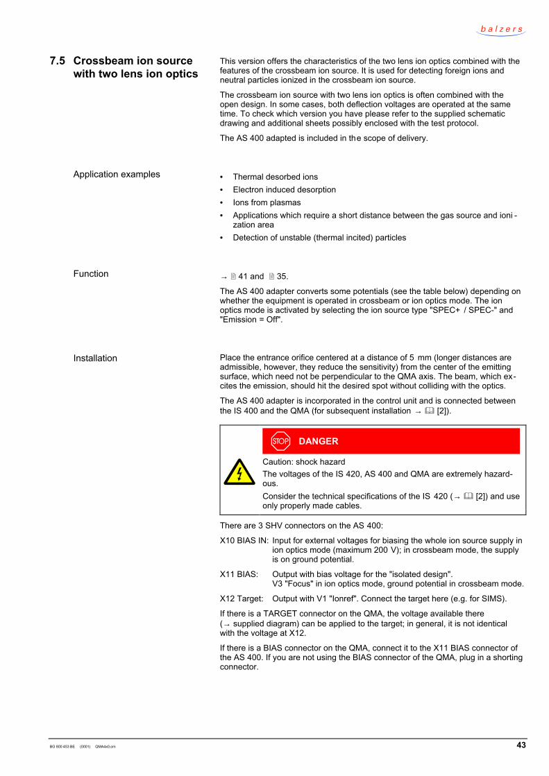
The ion optics mode is shown here; for crossbeam operation → 35 ff.
50 V
0
V2
V4
2
V1
V3
Entra
nce
orifi
ce
Rod
sys
tem
Lens
1
Lens
2
Targ
et
The values and adjustment apply to ions, emitted on a target. For other applica -tions, they may be quite different. Please note the values for your individualapplication in the table below.
Operating mode SPEC+/-Emission OFF
V0 X10 BIAS IN 0 V (shortingconnector)
V1 X12 Target 1) 80 VV2 Lens 1 // Cathode 70 VV3 Focus // Ionization
area // X11 BIAS20 V
V4 Field Axis 15 VV5 Extraction 250 VV6 Deflection 300 VV7 Lens 2 5 VV8 Target (QMA) ---V9 --- ---
1) Emission potential of the ions, e.g. connected to SIMS target.
Start with the values which previously supplied good results, with the values in thetest protocol or otherwise with the values of the above table.
First optimize for crossbeam mode and use the corresponding values forV3, V4, V5.
Adjust V1 to the maximum peak level (depending on distance of target).
Alternatingly adjust V2 and V7 to the maximum peak level.
If the peak shape is not satisfactory ("frays") or if the resolution ∆M10 = 1 isnot reached, reduce V1 and readjust V2 and V7.
Potentials
Electrode arrangement
Typical values
Adjustment

BG 800 453 BE (0001) QMA4x0.om 45
Adjust V6 "Deflection" to the maximum peak level.
Notes
46 BG 800 453 BE (0001) QMA4x0.om
The three lens ion optics with beam stop is suited for detecting positive and nega -tive ions in the presence of fast neutral particles.
The three lens ion optics have a high energy dispersion; they are used as energyfilter in connection with the mass filter.
The optics are often combined with an extraction hood, e.g. to extract ions from aplasma.
The three lens optics are often combined with an isolated design. In some cases,both deflection voltages are operated at the same time.
For a number of applications, the analyzer is differentially pumped in order for theminimum pressure of 10-5 mbar (10 -4 mbar with Faraday) to be reached.
To check which version you have please refer to the supplied schematic drawingand additional sheets possibly enclosed with the test protocol.
• = Secondary ion emission (SIMS).• = Analysis of thermal desorbed ions• = Detection of ions generated by photoionization• = Analysis of electron induced desorption• = Detection of positive and/or negative ions from plasmas• = Analysis of ion beams• = Energy analysis of ions from plasmas (PPM 400)
Place the entrance orifice centered at a distance of 5 mm (longer distances areadmissible, however, they reduce the sensitivity) from the center of the emittingsurface, which need not be perpendicular to the QMA axis. The beam, which ex-cites the emission, should hit the desired spot without colliding with the optics.
If there is a TARGET connector on the QMA, connect the supplied voltage to yourtarget.
If there is a BIAS connector on your QMA, connect the bias voltage of 0 ... 200 Vthere.
If there is a EXTR connector on the QMA, connect the voltage for the extractionhood 0 ... 60 V there.
DANGER
Caution: shock hazardThe voltages of the IS 420 as well as the additional BIAS, TARGETand EXTR voltages can be extremely hazardous.Consider the technical specifications of the IS 420 (→ [2]) and useonly properly made cables.
The ions to be analyzed pass from the formation area through the entrance orificeof Lens 1. The optics concentrate the diverging ions to the entrance orifice of themass filter.
Fast neutrals are eliminated by the beam stop in Lens 2 and thus do not contributeto the background signal.
The three lens ion optics act as energy filter with an energy resolution of approx.1.5 eV, depending on the entrance energy, bias voltage and potential distributionin the optics.
7.6 Three lens ion optics
Application examples
Installation
Function
BG 800 453 BE (0001) QMA4x0.om 47
50 V
0
-50 V
V1
V2 V8
V4
V5
Entra
nce
orifi
ceR
od s
yste
m
Lens
1
Lens
2
Lens
3
Targ
et
The values and adjustment apply to SIMS measurements. The values for otheranalyses may be quite different. In the table below, please note the values for yourindividual application.
V1 IonRef 50 V / Target 1)
V2 Lens 1 70 VV3 --- ---V4 Field Axis 5 VV5 Lens 2 20 VV6 DEFI 350 VV7 DEFO 100 VV8 Lens 3 100 VV9
1) Emission potential of the ions, e.g. connected to a SIMS target.
Start with the values which previously supplied good results, with the values in thetest protocol or otherwise with the values of the above table.
Adjust V1 to the maximum peak level (depending on the target distance).
Alternatingly adjust V2 and V5 to the maximum peak level.
Set V4 "Field Axis" so that a good peak shape and resolution ∆M10 = 1 arereached. If the peaks are still "frayed", reduce V1 and readjust V2 and V5.
Adjust V8 to the maximum peak level.
Adjust V7 "DEFO" to the maximum peak level.
Potentials
Electrode arrangement
Typical values
Adjustment

48 BG 800 453 BE (0001) QMA4x0.om
Try which is the better RF cable polarity (→ 31).
Notes
BG 800 453 BE (0001) QMA4x0.om 49
This version offers the characteristics of the three lens ion optics combined withthe features of the crossbeam ion source. It is used for detecting foreign ions andneutral particles ionized in the crossbeam ion source.
The crossbeam ion source with three lens ion optics is often combined with theisolated design. In some cases, both deflection voltages are operated at the sametime. To check which version you have please refer to the supplied schematicdrawing and additional sheets possibly enclosed with the test protocol.
The AS 400 adapted is included in the scope of delivery.
• = Secondary ion emission (SNMS / SIMS)• = Analysis of thermal desorbed ions• = Detection of ions generated by photoionization• = Analysis of electron induced desorption• = Detection of positive and/or negative ions from plasmas• = Analysis of ion beams• = Energy analysis of ions from plasmas
→ 46 and 35.
The AS 400 adapter converts some potentials (see the table below) depending onwhether the equipment is operated in crossbeam or ion optics mode. The ionoptics mode is activated by selecting the ion source type "SPEC+ / SPEC-" and"Emission = Off".
Place the entrance orifice centered at a distance of 5 mm (longer distances areadmissible, however, they reduce the sensitivity) from the center of the emittingsurface, which need not be perpendicular to the QMA axis. The beam, which ex-cites the emission, should hit the desired spot without colliding with the optics.
The AS 400 adapter is incorporated in the control unit and is connected betweenthe IS 400 and the QMA (for subsequent installation → [2]).
DANGER
Caution: shock hazardThe voltages of the IS 420, AS 400 and QMA are extremely hazard-ous.Consider the technical specifications of the IS 420 (→ [2]) and useonly properly made cables.
There are three 3 SHV connectors on the AS 400 :
X10 BIAS IN: Input for external voltages for biasing the whole ion source supply inion optics mode (maximum 200 V); in crossbeam mode, the supplyis on ground potential.
X11 BIAS: Output with bias voltage for the "isolated design".V3 "Focus" in ion optics mode, ground potential in crossbeam mode.
X12 Target: Output with V1 "Ionref". Connect the target here (e.g. for SIMS).
If there is a TARGET connector on the QMA, the voltage available there(→ supplied diagram) can be applied to the target; in general, it is not identicalwith the voltage at X12.
If there is a BIAS connector on the QMA, connect it to the X11 BIAS connector ofthe AS 400. If you are not using the BIAS connector of the QMA, plug in a shortingconnector.
If there is an EXTR connector on the QMA, connect the voltage for the extractionhood (0 ... 60 V) there.
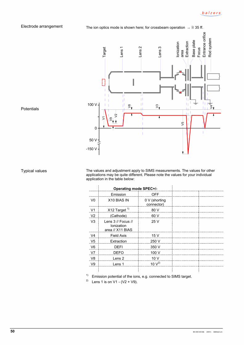
7.7 Crossbeam ion sourcewith three lens ionoptics
Application examples
Function
Installation
50 BG 800 453 BE (0001) QMA4x0.om
The ion optics mode is shown here; for crossbeam operation → 35 ff.
100 V
50 V
0
V1
V2
V8 V4
-150 V
V9
V5
V3
Ioni
zatio
nar
eaEx
tract
ion
Base
pla
teFo
cus
Entra
nce
orifi
ceR
od s
yste
m
Lens
2
Lens
1
Targ
et
Lens
3
The values and adjustment apply to SIMS measurements. The values for otherapplications may be quite different. Please note the values for your individualapplication in the table below:
Operating mode SPEC+/-Emission OFF
V0 X10 BIAS IN 0 V (shortingconnector)
V1 X12 Target 1) 80 VV2 (Cathode) 60 VV3 Lens 3 // Focus //
Ionizationarea // X11 BIAS
25 V
V4 Field Axis 15 VV5 Extraction 250 VV6 DEFI 350 VV7 DEFO 100 VV8 Lens 2 10 VV9 Lens 1 10 V2)
1) Emission potential of the ions, e.g. connected to SIMS target.2) Lens 1 is on V1 - (V2 + V9).
Electrode arrangement
Potentials
Typical values

BG 800 453 BE (0001) QMA4x0.om 51
Start with the values which previously supplied good results, with the values in thetest protocol or otherwise with the values of the above table.
First, optimize for crossbeam operation and use the corre sponding valuesfor V3, V4, V5.
Adjust V1 to the maximum peak level (depending on the target distance).
Alternatingly adjust V2+V9 and V8 to the maximum peak level.
If the peak shape is unsatisfactory ("frays") or if the resolution ∆M = 1 is notreached, reduce V1 and readjust V2 + V9 and V8.
Adjust V6 "Deflection" to the maximum peak level.
Adjustment

52 BG 800 453 BE (0001) QMA4x0.om
Notes
BG 800 453 BE (0001) QMA4x0.om 53
8 Maintenance and spare parts
→ [5]
9 Disposal
DANGER
Caution: contaminated partsContaminated parts can be detrimental to health.Before beginning to work, find out whether any parts are contami -nated. Adhere to the relevant regulations and take the necessaryprecautions when handling contaminated parts.
N
WARNING
Caution: substances detrimental to the environmentProducts, operating fluids etc. may require disposal in accordancewith special regulations.Dispose of such substances in accordance with the relevant localregulations.
After disassembling the product, separate its components according to the follow -ing criteria:
Contaminated components (radioactive, toxic, caustic, or biological hazard etc.)must be decontaminated in accordance with the relevant national regulations,separated according to their materials, and recycled.
Such components must be separated according to their materials and recycled.
Separating the components
Contaminated components
Other components
54 BG 800 453 BE (0001) QMA4x0.om
Appendix
[1] Technical informationPartial pressure measurement in vacuum technologyBG 800 169 PEBalzers Instruments, FL–9496 Balzers, Liechtenstein
[2] Operating manualQMG 422BG 800 451 BEBalzers Instruments, FL–9496 Balzers, Liechtenstein
[3] Operating manualQMH 400-1, -5, QMH 410-1, -2, -3BG 800 409 BEBalzers Instruments, FL–9496 Balzers, Liechtenstein
[4] Operating manualPPM 422BG 803 813 BEBalzers Instruments, FL–9496 Balzers, Liechtenstein
[5] Service instructionsQMA 4xxBG 800 118 KEBalzers Instruments, FL–9496 Balzers, Liechtenstein
A: Literature
BG 800 453 BE (0001) QMA4x0.om 55
Declaration of contamination
Legally binding declaration: I hereby declare that the information supplied on this form is complete and accurate. The dispatch of the contaminated product will be in accordance with the appropriate regulations covering packaging, transportation and labelling of dangerous substances.
Name of organization or company Address Post code, place Phone Fax E-Mail Name
Data and legally binding signature Company stamp
*) Products thus conta- minated will not be accepted without written evidence of decontamination!
Process related contamination of product: toxic no yes
corrosive no yes biological hazard no yes *) explosive no yes *) radioactive no yes *) other harmful substances no yes
The repair and/or service of vacuum equipment and components will only be carried out if a correctly completed declaration has beensubmitted. Non-completion will result in delay.This declaration can only be completed and signed by authorized and qualified staff.
Copies:Original to manufacturer or representative - 1 copy attach to consignment packaging - 1 copy for file of sender
Harmful substances, gases and/or by-products Please list all substances, gases and by-products which may have come into contact with the product:
Trade/product namemanufacturer
Chemical name(or symbol)
Dangerousmaterial class Measures if spillage
First aid in case ofcontact
Description of product Type Article No. Serial No.
Reason for return
Operating fluid(s) used
The product is free of any substanceswhich are damaging to health yes
Download:www.bi.balzers.com/library/misc
Balzers InstrumentsPostfach 1000FL–9496 BalzersLiechtensteinTel +423 / 388 50 31Fax +423 / 388 54 16
Original: German BG 800 453 BD (0001) [email protected]
www.bi.balzers.com
Declaration of conformity
QMG 422 Analyzers
QMA 400QMA 410QMA 430
We herewith declare that the products listed above comply with the provisions ofthe listed guidelines.
Guidelines, harmonized standards, national standards in languages and specifica -tions which have been applied:
89/336/EEC (7/93) ...........................................................
73/23/EEC (7/93) .............................................................
EN 61010-1 ..................................................................
EN 50081-2 ..................................................................
EN 50082-2 ..................................................................
.........................................................................................
.........................................................................................
Balzers, 17 September 1999 Balzers, 17 September 1999
Hans EpplerProduct management
Dr. Norbert MüllerProduct development
Product
EU declaration of conformity asdefined by the listed guidelines
Signatures


