PAU-SARA: a L1-GPS Band Radiometer and Reflectometerwith Digital Beamforming and Polarization Synthesis
3. SMIGOL Reflectometer
1. Working frequency = 1.57542 GHz (GPS L1)2. Measures the interference between direct and reflected signals during all the satellite passages.3. The IPT and the SMIGOL-Reflectometer can also be used to retrieve topography, soil moisture over vegetation-covered soils, and vegetation height as it has been tested in [1]
The Soil Moisture Interference-pattern GNSS Observations at L-band (SMIGOL) Reflectometer is theinstrument implementing the IPT.
[1] Rodriguez-Alvarez, N., Camps, A., Vall-Llossera, M., Bosch-Lluis, X., Monerrris, A., Ramos-Perez, I., Valencia, E., Marchan-Hernandez, J.F., Martinez-Fernandez,J., Baroncini-Turricchia, G., Pérez-Gutiérrez C., Sánchez, N., “Land Geophysical Parameters Retrieval Using The Interference Pattern GNSS-R Technique” IEEE Transactions on Geoscience and Remote Sensing, DOI: 10.1109/TGRS.2010.2049023
You can find more information about SMIGOL-Reflectometer and the IPT in the poster session, where a summaryof their applications is shown.
LAND RETRIEVALS: THE SMIGOL-REFLECTOMETER AND THE INTERFERENCE PATTERN TECHNIQUE
PAU-SARA: a L1-GPS Band Radiometer and Reflectometerwith Digital Beamforming and Polarization Synthesis
3. Fundamentals of the Interference Pattern Technique
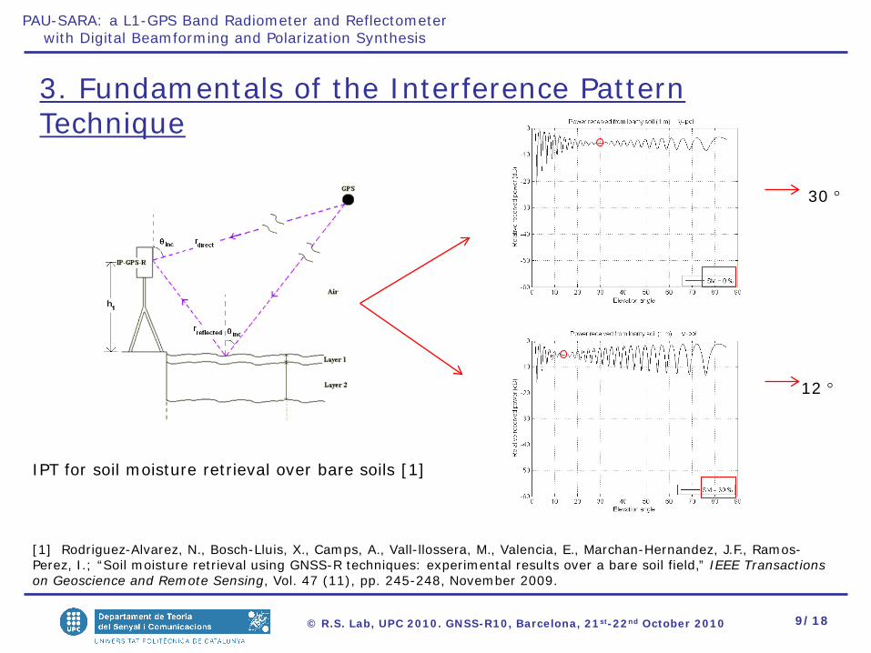
IPT for soil moisture retrieval over bare soils [1]
[1] Rodriguez-Alvarez, N., Bosch-Lluis, X., Camps, A., Vall-llossera, M., Valencia, E., Marchan-Hernandez, J.F., Ramos-Perez, I.; “Soil moisture retrieval using GNSS-R techniques: experimental results over a bare soil field,” IEEE Transactions on Geoscience and Remote Sensing, Vol. 47 (11), pp. 245-248, November 2009.
PAU-SARA: a L1-GPS Band Radiometer and Reflectometerwith Digital Beamforming and Polarization Synthesis
5. Conclusions
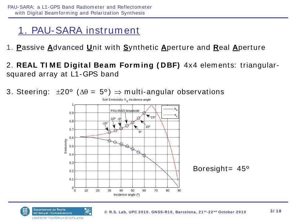
1. A radiometer with DBF at GPS-L1 band has successfully developed and tested for radiometric applications,( it is possible to neglect the GPS impact with θi= 45 and a narrow beam, ~ 0.3 K of impact when entering from the side lobes),
2. it is recommended to have a GPS receiver to ensure that there is no GPS satellite presence corrupting the measurements. If possible, pointing the instrument to the North(no Satellites),
3. when the GPS signal is corrupting a measurement, RFI techniques can be applied to nitigate the GPS effect on the radiometric data,
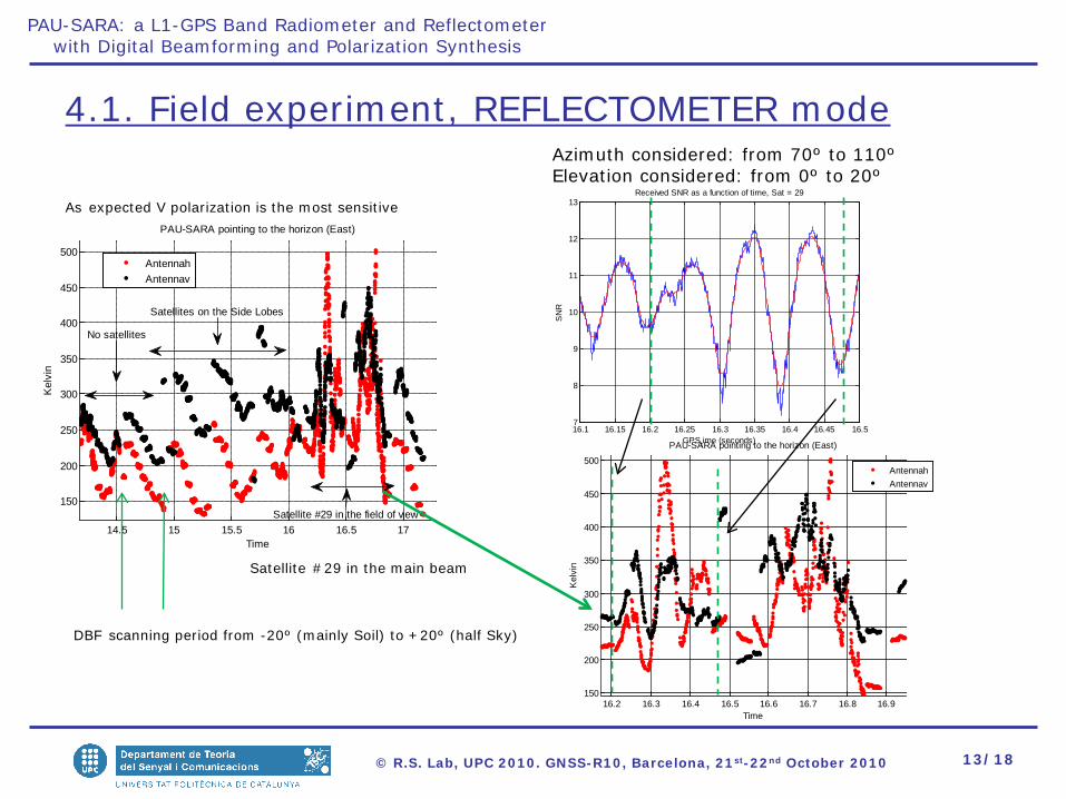
4. with the PAU-SARA antenna, when looking to the horizon the GPS can increase the measured power 300 K, without correlating it with any PRN code,
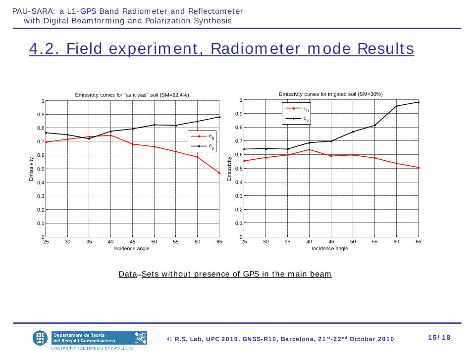
5. PAU-SARA can also successfully work as a IP-Reflectometer despite it only measures power, really convenient to make SM maps (better using a high bandwitdh antenna), and
6. Keep on working on collected data sets to retrieve SM information from collected data sets.
PAU-SARA: a L1-GPS Band Radiometer and Reflectometerwith Digital Beamforming and Polarization Synthesis
-80 -60 -40 -20 0 20 40 60 80-30
-25
-20
-15
-10
-5
0
Scanned angle θ (º)
Nor
mal
ized
arra
y fa
ctor
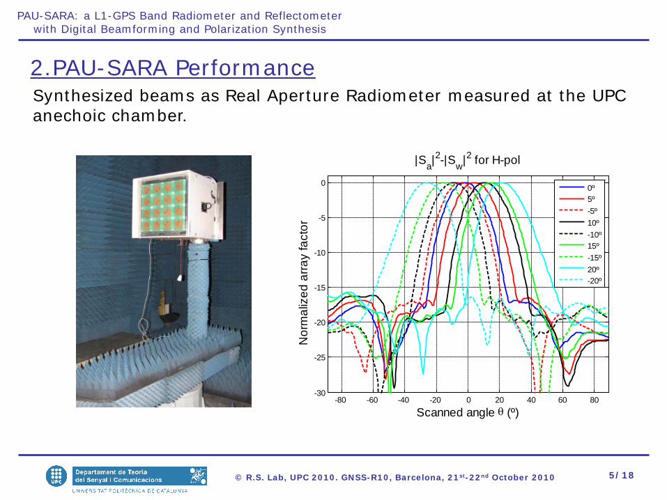
|Sa|2-|Sw|2 for H-pol
0º10º-10º20º-20º
-80 -60 -40 -20 0 20 40 60 80-30
-25
-20
-15
-10
-5
0
SYNTHETIC IMAGE
Angle [degree]
Nor
mal
ized
imag
e re
cons
truci
ton
[dB
]
0o
-10o
-20o
10o
20o
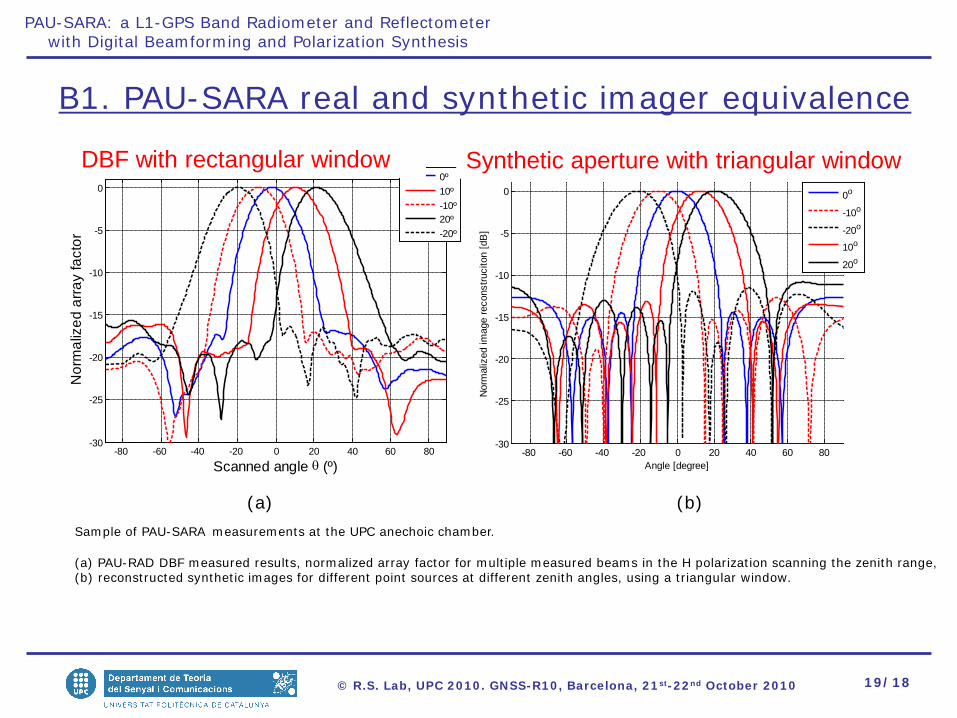
Sample of PAU-SARA measurements at the UPC anechoic chamber.
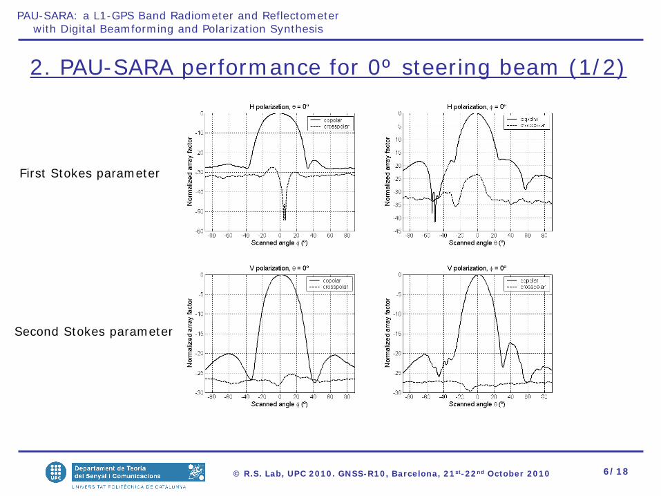
(a) PAU-RAD DBF measured results, normalized array factor for multiple measured beams in the H polarization scanning the zenith range,(b) reconstructed synthetic images for different point sources at different zenith angles, using a triangular window.
(a) (b)
B1. PAU-SARA real and synthetic imager equivalence
DBF with rectangular window Synthetic aperture with triangular window