Laser Telecom 60 LT-0400 Optical Time Domain Reflectometer Pulsed Laser Diode Optical Fibre Fibre Stripping Fibre cutting Speed of Light Length of Fibre Losses of Fibres Losses of Connectors Fast Photo Detector Light Echoes The whole worldwide commu- nication is based on fibre optical networks encompassing the entire world and is extremely important in view of economical and secu- rity aspects. Meanwhile fibre optical networks lines already terminating at homes thus form- ing a complex structure. The proper working and condition is of vital mutual interest of the provider and customer. Fibre lines can be dam- aged during road works, earth movements and even by late effects of production imperfec- tions. Whatever the reason of the malfunction of communication networks are, the problems needs to be solved as soon as possible. This is the moment of the mission of the “Optical Time Reflectometry” (OTDR). An OTDR is an opto- electronics instrument that uses time-domain reflectometry to characterize and locate faults in optical fibres. The underlying idea is to send a short pulse into the fibre and “listening” to any echoes coming back from it. At each fibre imperfection, especially at the face of a broken fibre a lot of light is reflected or scattered back into the fibre. From the time of flight of the in- put pulse and the occurrence of the echoes the distance to the faulty position is found and the service repair team can then do their job. However, the OTDR covers more possibilities, it is the only device which can measure the attenuation or losses of an optical fibre non- destructively. Such losses in optical fibres can be caused by several reasons, mainly due to op- tical and mechanical imperfections during the manufacturing process, or by extra mechanical stress on the fibres like unspecified bending or tension. These days OTDR devices form a small and compact and an indispensable tool in optical fibre communication. The aim of this experi- ment is to set up an OTDR in such a way that the trainees can identify, align and control the required components like the pulsed diode la- ser, coupling light into the fibre via a polarising beam splitter. The path of the returning light is bent due to its changed polarisation at the beam splitter cube towards the fast photode- tector. The returned light intensity carries the information about the losses by an exponential decay in time, upward peaks for reflections and downward peaks for losses at joints caused ei- ther by splices or connectors. The experiment comes with two drums carrying each 1000 m of optical fibre. The fibres are interconnected via two ST patch cable whereby one end of each fibre is left as it is to teach fibre stripping and cutting. L2 L1 PD PLD RPD Polarising beam splitter plate Adjustable launching optics Optical glass fibre Quarter waveplate Main reasons for losses in optical fibre are me- chanical cracks, unavoidable scatter centres due to the production process and reflections (see Fig. 3.15). These three imperfections creat- ing backward oriented scatter light, where by optical connectors acting as a photon sink. The idea of an OTDR is to detect this back scat- tered light and analyse its amplitude and tempo- ral behaviour. For this purpose the pulse of the laser diode (PLD) is launched via a polarising beam splitter plate into the optical fibre. The polarisation of the back scattered is changed so that it will be reflected at the beam splitter towards the detector. The quarter waveplate further enhances the right polarisation in order to get most of the back scattered light which anyhow has a very small power. This requires highly sensitive photodiodes and fast amplifier. 100%→ cracks scatter centres reflection <96% ←4% Fig. 3.15: Losses in optical fibre Within this experiment an extra photodetector as alignment aid is used. It serves as indicator for the coupling efficiency of the laser light into the fibre. Further more in first experiments the time of flight inside the fibre can be measured with this photodetector as well. Keywords Introduction How it works
Transcript
Laser Telecom
60
LT-0400 Optical Time Domain Reflectometer
Pulsed Laser Diode Optical Fibre Fibre StrippingFibre cutting Speed of Light Length of FibreLosses of Fibres Losses of Connectors Fast Photo DetectorLight Echoes
The whole worldwide commu-nication is based on fibre optical networks encompassing the entire world and is extremely important in view of economical and secu-
rity aspects. Meanwhile fibre optical networks lines already terminating at homes thus form-ing a complex structure. The proper working and condition is of vital mutual interest of the provider and customer. Fibre lines can be dam-aged during road works, earth movements and even by late effects of production imperfec-tions. Whatever the reason of the malfunction of communication networks are, the problems needs to be solved as soon as possible. This is the moment of the mission of the “Optical Time Reflectometry” (OTDR). An OTDR is an opto-electronics instrument that uses time-domain reflectometry to characterize and locate faults
in optical fibres. The underlying idea is to send a short pulse into the fibre and “listening” to any echoes coming back from it. At each fibre imperfection, especially at the face of a broken fibre a lot of light is reflected or scattered back into the fibre. From the time of flight of the in-put pulse and the occurrence of the echoes the distance to the faulty position is found and the service repair team can then do their job.However, the OTDR covers more possibilities, it is the only device which can measure the attenuation or losses of an optical fibre non-destructively. Such losses in optical fibres can be caused by several reasons, mainly due to op-tical and mechanical imperfections during the manufacturing process, or by extra mechanical stress on the fibres like unspecified bending or tension.These days OTDR devices form a small and
compact and an indispensable tool in optical fibre communication. The aim of this experi-ment is to set up an OTDR in such a way that the trainees can identify, align and control the required components like the pulsed diode la-ser, coupling light into the fibre via a polarising beam splitter. The path of the returning light is bent due to its changed polarisation at the beam splitter cube towards the fast photode-tector. The returned light intensity carries the information about the losses by an exponential decay in time, upward peaks for reflections and downward peaks for losses at joints caused ei-ther by splices or connectors. The experiment comes with two drums carrying each 1000 m of optical fibre. The fibres are interconnected via two ST patch cable whereby one end of each fibre is left as it is to teach fibre stripping and cutting.
L2
L1
PD
PLDRPD
Polarising beam splitter plate
Adjustable launching opticsOptical glass fibre
Quarter waveplate
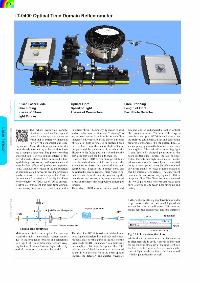
Main reasons for losses in optical fibre are me-chanical cracks, unavoidable scatter centres due to the production process and reflections (see Fig. 3.15). These three imperfections creat-ing backward oriented scatter light, where by optical connectors acting as a photon sink.
The idea of an OTDR is to detect this back scat-tered light and analyse its amplitude and tempo-ral behaviour. For this purpose the pulse of the laser diode (PLD) is launched via a polarising beam splitter plate into the optical fibre. The polarisation of the back scattered is changed so that it will be reflected at the beam splitter towards the detector. The quarter waveplate
further enhances the right polarisation in order to get most of the back scattered light which anyhow has a very small power. This requires highly sensitive photodiodes and fast amplifier.
100%→
cracks
scatter centres
reflection
<96%
←4%
Fig. 3.15: Losses in optical fibreWithin this experiment an extra photodetector as alignment aid is used. It serves as indicator for the coupling efficiency of the laser light into the fibre. Further more in first experiments the time of flight inside the fibre can be measured with this photodetector as well.
Keyw
ords
Intro
duct
ion
How
it w
orks
Lase
r Tel
ecom
m
5 76
1117
13
16 12
1820
19
21
2214
15
10
9
8
The light of the pulsed diode laser (9) is col-limated (11) to an almost parallel beam and
guided via the polarising beam splitter (21), the quarter wave plate (17) and the launching optics
into the fibre (20) under test. The fibre drum is connected via a pigtailed fibre patch cable to the adjustable fibre holder (12). The exit of the fibre drum is connected via a patch cable (18) to the photodetector (6). The junction box (8) converts the photocurrent into a voltage which is displayed on an oscilloscope. The adjust-able launching optics and the translation stage of (12) is used to couple the light into the fibre while observing the signal of the photodetector (6) on the oscilloscope. Once the optimum set-tings has ben achieved, the signal of the pho-todiode (7) is monitored, which represents the intensity of the back scattered light as shown in (Fig. 3.16).
Kea measurements
“End of fibre” peak
Puls laser
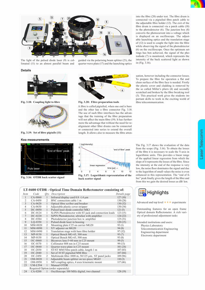
Fig. 3.16: OTDR back scatter signal
-6
-4
-2
0
0 2
↑ log(Intensity)
linear regression
“end of fibre” peak
time [µs] →4 6 8 10 12
Fig. 3.17: Logarithmic representation of the back scatter signal
The Fig. 3.17 shows the evaluation of the data from the scope (Fig. 3.16). To obtain the losses of the fibre it is necessary to scale the Y-axis in logarithmic units. This provides a linear range of the applied linear regression from which the slope of it represents the losses of the fibre. Since the intensity at the end of the response is very low, the noise floor dominates the signal and due to the logarithm of small values the noise is even enhanced in this representation. The “end of fi-bre” peak finally gives the length of the fibre and from this we gain the desired losses as dB/ km.
Details
Fig. 3.18: Coupling light to fibre
Fig. 3.19: Set of fibre pigtails (11)
3
4
Fig. 3.20: Fibre preparation toolsA fibre is called pigtailed, when one end is bare and the other has a fibre connector Fig. 3.18. The use of such fibre interfaces has the advan-tage that the training of the fibre preparation will not affect the main fibre (19). It has further-more the advantage that without the need for re-alignment other fibre drums can be connected or connected into series to extend the overall length. It allows also to measure the fibre atten-
uation, however including the connector losses.To prepare the fibre for operation a flat and clean surface of the fibre face is needed. Firstly the plastic cover and cladding is removed by the so called Miller’s pliers (4) and secondly scratched and broken by the fibre breaking tool (3). This practical work gives the students im-portant skills to work in the exciting world of fibre telecommunication.