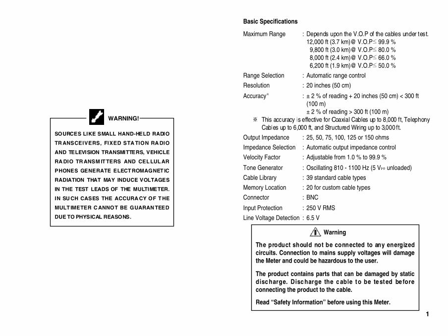
The product should not be connected to any energizedcircuits. Connection to mains supply voltages will damagethe Meter and could be hazardous to the user.
The product contains parts that can be damaged by staticdisc harge. Disc harge the c able to be te sted be foreconnecting the product to the cable.
Read “Safety Information” before using this Meter.
1
1. Safety Information 32. The TDR Cable Length Meter 43. Controls, Indicators, and Buttons Overview 54. Meter Operation 8
4.1 Principles of operation 84.2 How to connect a cable to the Meter 84.3 How to set the cable type 9
4.3.1 Selecting a library cable type 94.3.2 Cable library for 39 standard cable types 104.3.3 Testing cables not included in library 12
4.4 How to determine unknown V.O.P settings 144.4.1 Expanding cable library
for custom cable types using nonvolatile memory 154.5 How to measure cable length 194.6 How to check networks (Thin Ethernet) 19
5. Changing the measurement scale between English and Metric 206. Measurement accuracy 217. Theoretical and actual V.O.P 228. Special features 23
8.1 Low battery indication 238.2 Overrange indication 238.3 Enable or disable the auto-power-off mode 248.4 Tone Generator mode 258.5 Line Voltage Detection mode 25
9. Maintenance 2610. Specifications 27Repair and Warranty
CONTENTS
Safety Warnings
This Meter c omplies with the safety requirements of IEC 1010-1 : 2001. It isdesigned for use on de-energized circuits only, however this Meter is protectedagainst telephone networking voltages (EN 60950 : 1999 Sec. 2.3). Connection toany mains supply voltages may result in damage to the Meter and/or a hazard tothe user. Hence the user must assume responsibility for ensuring his or her ownsafety.
EMC Standard Category of PassESD IEC 1000-4-2 AEM IEC 1000-4-3 ABurst IEC 1000-4-4 ASurge IEC 1000-4-5 AConducted RF IEC 1000-4-6 A
2 3
The Meter is a handheld and battery operated instrument capable of measuringcable lengths and finding distance to an open or a short using TDR(Time DomainReflectometry) techniques, given access to one end only.
The Meter can be used for any cable consisting of at least two insulated metallicelements, one of which may be the sheath or shield of the cable. The Meter hasautomatic internal matching networks to allow testing of 25 , 50 , 75 , 100 ,125 , or 150 cables, which correspond to power, telephony, CATV, and LAN,etc. cables.
The Meter can be closely matched to the cable under test using the menu selectionkeys. The V.O.P(Velocity of Propagation) value can be similarly adjusted to matchthe cable under test; thus ensuring an accurate distance measurement.
The Meter incorporates an oscillating tone generator, that is detectable with astandard tone probe (not supplied) available in the marketplaces, for use in thetracing and identification of pairs within a cable .
The Meter displays “ ” message and stops operation if line voltage of the cableunder test exceeds 6.5 V when the Meter is turned on. The BNC terminal isprotected up to 250 V RMS in order to prevent it from being demaged by itsmisconnection to live circuits of networking.
You can s tore up to 20 cable test results for custom cable types in internalnonvolatile memory and the stored cable library provides quick and easy access to39 standard c able types, which enables ac curate measurement without thenecessity of entering V.O.P (Velocity of Propagation).
The on-site measurement scale changing feature enables the Meter to be globallyused for both Metric measurement and English measurement without changing themeasurement scale at factory.
The Meter comes with an Alligator Clip adaptor, a user’s manual and a soft carryingcase.
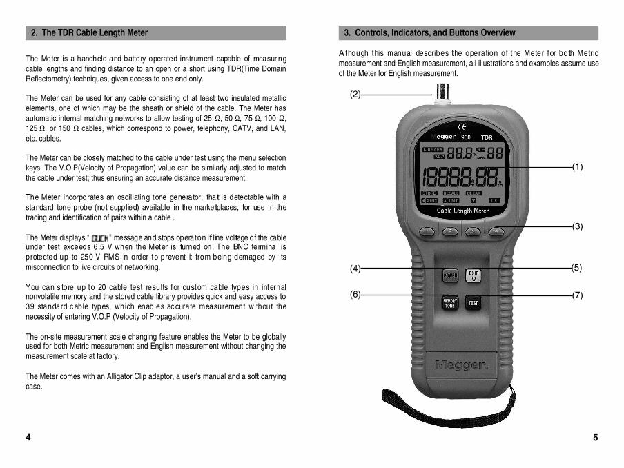
2. The TDR Cable Length Meter
Although this manual describes the operation of the Meter for both Metricmeasurement and English measurement, all illustrations and examples assume useof the Meter for English measurement.
( 1 )
( 3 )
( 4 )
( 7 )
( 5 )
( 6 )
( 2 )
3. Controls, Indicators, and Buttons Overview
54
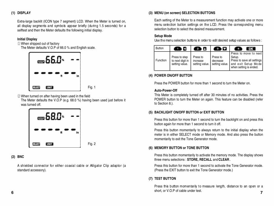
(3) MENU (on screen) SELECTION BUTTONS
Each setting of the Meter to a measurement function may activate one or moremenu selection but ton settings on the LCD. Press the corresponding menuselection button to select the desired measurement.
Setup ModeUse the menu selection buttons in order to edit desired setup values as follows :
(4) POWER ON/OFF BUTTON
Press the POWER button for more than 1 second to turn the Meter on.
Auto-Power-OffThis Meter is completely turned off after 30 minutes of no activities. Press thePOWER button to turn the Meter on again. This feature can be disabled (referto Section 8.).
(5) BACKLIGHT ON/OFF BUTTON or EXIT BUTTON
Press this button for more than 1 second to turn the backlight on and press thisbutton again for more than 1 second to turn it off.
Press this button momentarily to always return to the initial display when themeter is in either SELECT mode or Memory mode. And also press the buttonmomentarily to exit the Tone Generator mode.
(6) MEMORY BUTTON or TONE BUTTON
Press this button momentarily to activate the memory mode. The display showsthree menu selections : STORE, RECALL and CLEAR.
Press this button for more than 1 second to activate the Tone Generator mode.(Press the EXIT button to exit the Tone Generator mode.)
(7) TEST BUTTON
Press this button momentarily to measure length, distance to an open or ashort, or V.O.P of cable under test.
(1) DISPLAY
Extra-large backlit (ICON type 7 segment) LCD. When the Meter is turned on,all display segments and symbols appear briefly (during 1.5 seconds) for aselftest and then the Meter defaults the following initial display.
Initial DisplayWhen shipped out of factoryThe Meter defaults V.O.P of 66.0 % and English scale.
When turned on after having been used in the field The Meter defaults the V.O.P (e.g. 68.0 %) having been used just before itwas turned off.
(2) BNC
A shielded connector for either coaxial cable or Alligator Clip adaptor (astandard accessory).
Fig. 1
Fig. 2
Button
FunctionPress to stepto next digit insetting value.
Press toincreasesetting value.
Press todecreasesetting value.
Press to move t o nextSetup.Press to save all settingsand e xit Set up Mo dewhen setting is ended.
76
4.1 Principles of operation
The Meter works by measuring the time taken for a signal to travel to the far end ofthe cable (or to an intermediate fault) and to return.
The velocity at which the signal is t ransmitted (Velocity of Propagat ion, that is,V.O.P) will depend upon the characteristics of the cable to be tested.
The length is computed from the following formula :travel time X (9.84 X 10⁸) X V.O.P (English measurement)travel time X (3 X 10⁸) X V.O.P (Metric measurement)
The V.O.P is specified for standard cable types in this manual. However, do not relysolely on the specified V.O.P because variations of up to 20 % can occur betweenbatches of cable. Therefore, if accuracy is critical to your situation, y ou mustdetermine the ac tual V.O.P of each cable. Verify the length measurement bymeasuring a sample cable (longer than 30 ft, or 10 m) of the same cable type youwill be testing.
4.2 How to connect a cable to the Meter
Ensure that no power supply or equipment is connected to the cable to be tested.Ensure that the far end of the cable to be tested is either open or shorted (notfitted with a terminator).Connect the Meter to one end of the cable to be tested.
The cable connection to the Meter is via a BNC connector located at the top of theMeter. For unterminated cables use the Alligator Clip adaptor as follows.
Coaxial cable : Connect the red clip to the center wire and the blackclip to the shield.
Shielded cable : Connect the red clip to a wire adjacent to the shield ofthe cable and the black clip to the shield.
Unshielded twistedpair cable : Separate one pair out and connect the two clips to the
two wires of a pair.
Unshielded multi-corecable : Connect the two clips to any two wires.
4.3 How to set the cable type
The Meter needs to be set for the cable type to be tested before being used to takemeasurements.
If the cable type is listed in the library, setting up is simply a matter of selecting theappropriate cable type from the library.
4.3.1 Selecting a library cable type
The library cable type you will select determines the information about V.O.P andthe abbreviated trade name of the cable to be tested.
1. Turn the Meter on.
2. The Meter will display the previously selected cable setting (see Fig. 1 andFig. 2) with its V.O.P.
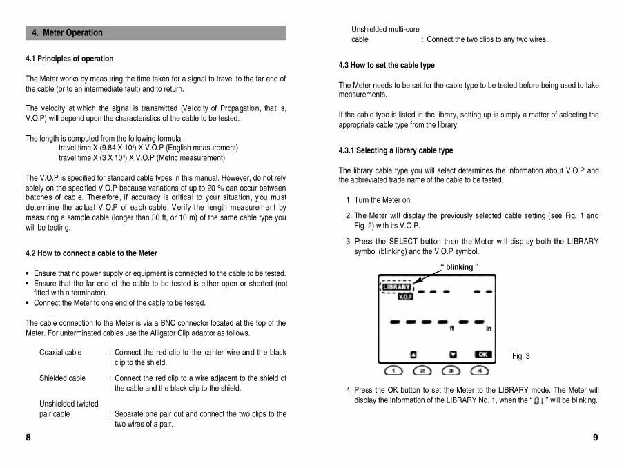
3. Press the SELECT button then the Meter will display both the LIBRARYsymbol (blinking) and the V.O.P symbol.
4. Press the OK button to set the Meter to the LIBRARY mode. The Meter willdisplay the information of the LIBRARY No. 1, when the “ ” will be blinking.
4. Meter Operation
Fig. 3
98
“ blinking ”
5. Scroll through the library using the , and buttons to find the requiredcable type. The types are displayed in the Library Number order. The 39standard cable types are listed in Section 4.3.2 and Section 4.3.3 will explainyou how to make the library of 20 customer cable types using the memorymode.
6. Press the OK button to set the Meter to the required cable type.
The center line segments of 6 digits in the lower display will be blinking untilthe TEST button will be depressed.
7. Connect the cable to be tested to BNC connector of the Meter.
8. Press the TEST button to take the required measurements.
The displayed V.O.P will be remained on the LCD even af ter the TESTbutton was depressed in order to inform the user of the V.O.P of the cableto be tested.
When the Meter will be continuously set to the just same cable type as thepreceding cable type, the Meter will show the preceding display until theTEST button will be newly depressed.
When the Meter is turned off it automatically stores the last setting and willdisplay this setting when powered up.
Fig. 4
1110
“ blinking ”
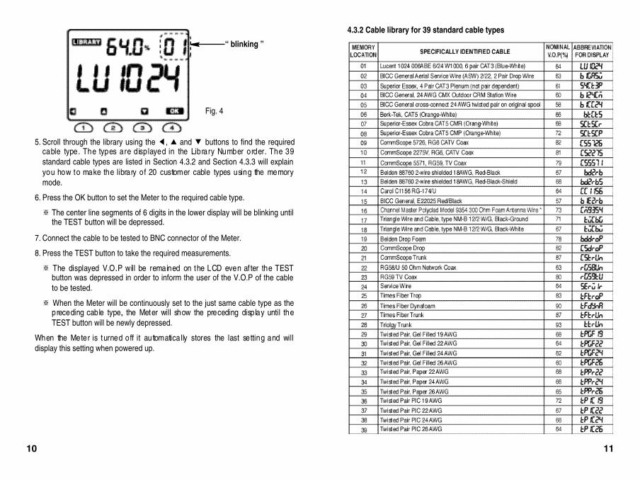
4.3.2 Cable library for 39 standard cable types
4.3.3 Testing cables not included in library
If the cable type to be tested is not in the library, it can still be tested if the V.O.P isknown. If the V.O.P is unknown, refer to Section 4.4.
1 . Turn the Meter on.
2 . The Meter will display the previously selected cable setting [see Initial Display ofSection 3.(1)] with its V.O.P.
3 . Press the SELECT button then the Meter will d isplay both the LIBRARY symbol(blinking) and the V.O.P symbol (see Fig. 3).
4 . Press the button then the LIBRARY symbol will stop blinking and the V.O.Psymbol will be blinking.
5 . Press the OK button to set the Meter to the V.O.P adjusting mode, when theLIBRARY symbol will disappear, the V.O.P symbol will stop blinking, and the “ ”segments will start to blink.
The Meter can enter into the Calibrate Cable function to determine theV.O.P for a known length of cable by pressing any button out of and buttons when the Meter is in the V.O.P adjusting mode. Then, the willappear replacing the and “ 30.00 ” will be blinking to alert the user thata sample cable longer than 30 ft (10 m) is necessary.
Fig. 5
6. Press the OK button again then the default V.O.P value of 66.0 % will start toblink.
7. Scroll through the V.O.P value between 1.0 % and 99.9 % by using the ,and buttons to find the required V.O.P value.
8 . Press the OK button to set the Meter to the required V.O.P value.
9 . Connect the cable to be tested to BNC connector of the Meter.
1 0 . Press the TEST button to take the required measurements.For example, the Meter can have the following display.
Fig. 6
Fig. 7
1312
“ blinking ”
“ blinking ”
4.4 How to determine unknown V.O.P settings
The Calibrate Cable function allows you to determine the V.O.P for a known lengthof cable and save it for additional measurements of unknown lengths of the sametype of cable. V.O.P settings are stored in nonvolatile memory.
To calibrate a cable manually, perform the following steps :
1 . Take a sample of the c able at least 30 ft (10 m) in length to obtain thespecified accuracy (longer lengths improve accuracy).
2 . Measure its length by direct measurement.
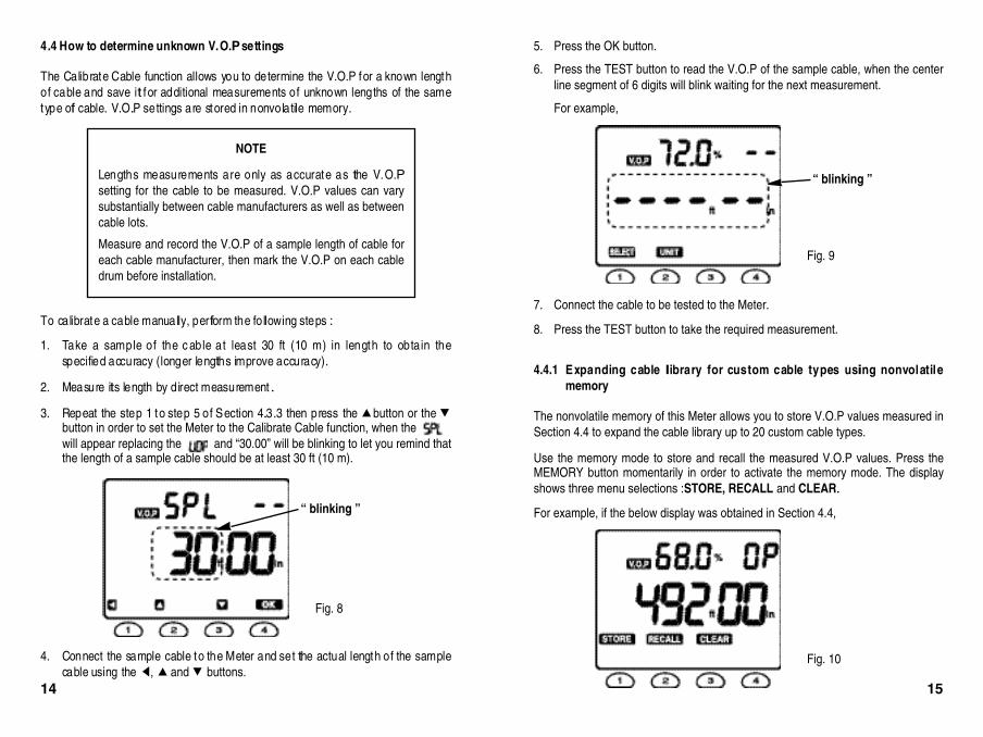
3 . Repeat the step 1 to step 5 of Section 4.3.3 then press the button or the button in order to set the Meter to the Calibrate Cable function, when the will appear replacing the and “30.00” will be blinking to let you remind thatthe length of a sample cable should be at least 30 ft (10 m).
4 . Connect the sample cable to the Meter and set the actual length of the samplecable using the , and buttons.
NOTE
Lengths measurements are only as accurate as the V.O.Psetting for the cable to be measured. V.O.P values can varysubstantially between cable manufacturers as well as betweencable lots.
Measure and record the V.O.P of a sample length of cable foreach cable manufacturer, then mark the V.O.P on each cabledrum before installation.
Fig. 8
5. Press the OK button.
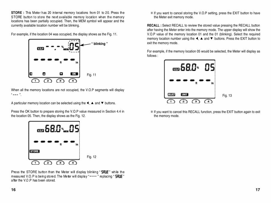
6. Press the TEST button to read the V.O.P of the sample cable, when the centerline segment of 6 digits will blink waiting for the next measurement.
For example,
7. Connect the cable to be tested to the Meter.
8. Press the TEST button to take the required measurement.
4.4.1 Expanding cable library for custom cable types using nonvolatilememory
The nonvolatile memory of this Meter allows you to store V.O.P values measured inSection 4.4 to expand the cable library up to 20 custom cable types.
Use the memory mode to store and recall the measured V.O.P values. Press theMEMORY button momentarily in order to activate the memory mode. The displayshows three menu selections : STORE, RECALL and CLEAR.
For example, if the below display was obtained in Section 4.4,
Fig. 9
Fig. 10
1514
“ blinking ”
“ blinking ”
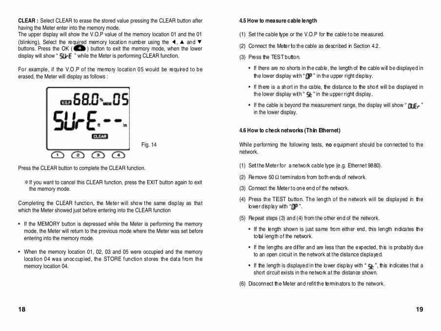
STORE : This Meter has 20 internal memory locations from 01 to 20. Press theSTORE button to store the next available memory locat ion when the memorylocations has been partially occupied. Then, the MEM symbol will appear and thecurrently available location number will be blinking.
For example, if the location 04 was occupied, the display shows as the Fig. 11.
When all the memory locations are not occupied, the V.O.P segments will display“ ”.
A particular memory location can be selected using the , and buttons.
Press the OK button to prepare storing the V.O.P value measured in Section 4.4 inthe location 05. Then, the display shows as the Fig. 12.
Press the STORE button then the Meter will d isplay blinking “ ” while themeasured V.O.P is being stored. The Meter will d isplay “ ” replacing “ ”after the V.O.P has been stored.
Fig. 11
If you want to cancel storing the V.O.P setting, press the EXIT button to havethe Meter exit memory mode.
RECALL : Select RECALL to review the stored value pressing the RECALL buttonafter having the Meter enter into the memory mode. The upper display will show theV.O.P value of the memory location 01 and the 01 (blinking). Select the requiredmemory location number using the , and buttons. Press the EXIT button toexit the memory mode.
For example, if the memory location 05 would be selected, the Meter will display asfollows :
If you want to cancel this RECALL function, press the EXIT button again to exitthe memory mode.
Fig. 12
Fig. 13
16 17
“ blinking ”
”.
CLEAR : Select CLEAR to erase the stored value pressing the CLEAR button afterhaving the Meter enter into the memory mode.The upper display will show the V.O.P value of the memory location 01 and the 01(blinking), Select the required memory locat ion number using the , and buttons. Press the OK ( ) button to exit the memory mode, when the lowerdisplay will show “ ” while the Meter is performing CLEAR function.
For example, if the V.O .P of the memory locat ion 05 would be required to beerased, the Meter will display as follows :
Press the CLEAR button to complete the CLEAR function.
If you want to cancel this CLEAR function, press the EXIT button again to exitthe memory mode.
Completing the CLEAR funct ion, the Meter will show the same display as thatwhich the Meter showed just before entering into the CLEAR function
If the MEMORY button is depressed while the Meter is performing the memorymode, the Meter will return to the previous mode where the Meter was set beforeentering into the memory mode.
When the memory location 01, 02, 03 and 05 were occupied and the memorylocation 04 was unoc cupied, the STORE function stores the data f rom thememory location 04.
Fig. 14
4.5 How to measure cable length
( 1 ) Set the cable type or the V.O.P for the cable to be measured.
( 2 ) Connect the Meter to the cable as described in Section 4.2.
( 3 ) Press the TEST button.
If there are no shorts in the cable, the length of the cable will be displayed inthe lower display with “ ” in the upper right display.
If there is a short in the cable, the distance to the short will be displayed inthe lower display with “ ” in the upper right display.
If the cable is beyond the measurement range, the display will show “ ”in the lower display.
4.6 How to check networks (Thin Ethernet)
While performing the following tests, n o equipment should be connected to then e t w o r k .
( 1 ) Set the Meter for a network cable type (e.g. Ethernet 9880).
( 2 ) Remove 50 W terminators from both ends of network.
( 3 ) Connect the Meter to one end of the network.
( 4 ) Press the TEST button. The length of the network will be displayed in thelower display with “
( 5 ) Repeat steps (3) and (4) from the other end of the network.
If the length shown is just same from either end, this length indicates thetotal length of the network.
If the lengths are dif fer and are less than the expected, this is probably dueto an open circuit in the network at the distance displayed.
If the length is displayed in the lower display with “ ”, this indicates that ashort circuit exists in the network at the distance shown.
( 6 ) Disconnect the Meter and refit the terminators to the network.
18 19
Choice of the measurement units : This Meter can display cable lengths inei ther Engli sh s ys tem (f t, i n) or Met ric s ys tem ( m, cm). T o change themeasurement sc ale system, press the UNIT button after the previous lengthmeasurement is carried out. Then, the Meter will display “ ” in the lowerdisplay as the following example for English to Metric measurement conversion.
Press the TEST button to read the cable length in Metric scale.
Please note that this feature enables the Meter compatible with both Englishscale system and Metric scale system very conveniently without returning theMeter to factory.
5. Changing the Measurement Scale between English and Metric
Fig. 15
For coaxial, twisted pair and shielded cable types, an accuracy of 2 % (ofreading) can be expected, or 20 in (0.5 m) for a cable less than 30 ft (10 m).
The V.O.P is less well defind with unshielded multicore cable (including mainscable) and is lower when the cable is tightly wound on a spool than when it isinstalled. This is due to capacitance and inductance effects between the turns.Therefore, the accuracy for these cables can be a little bit deteriorated.
The BNC to Alligator Clip adaptor has an effective length of 8 inches (20 cm).
6. Measurement Accuracy
20 21
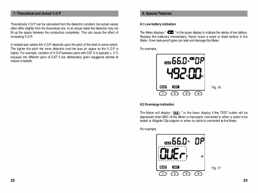
8.1 Low battery indication
The Meter displays “ ” in the upper display to indicate the status of low battery.Replace the batteries immediately. Never leave a weak or dead battery in theMeter. Even leak-proof types can leak and damage the Meter.
For example,
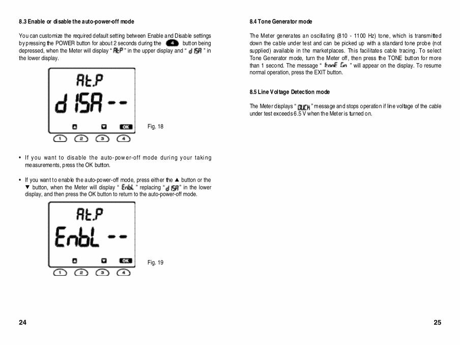
8.2 Overrange indication
The Meter will display “ ” in the lower display if the TEST button will bedepressed when BNC of the Meter is improperly connected to either a cable to betested or Alligator Clip adaptor or when no cable is connected to the Meter.
For example,
8. Special Features
Fig. 16
Fig. 17
Theoretically V.O.P can be calculated from the dielectric constant, but actual valuesoften differ slightly from the theoretical one. In an actual cable the dielectric may notfill up the space between the conductors completely. This can cause the effect ofincreasing V.O.P.
In twisted pair cables the V.O.P depends upon the pitch of the twist to some extent.The tighter the pitch the more dielect ric and the less air space so the V.O.P ishigher. For example, variation of V.O.P between pairs with CAT 5 is typically ± 2 %because the different pairs of CAT 5 are deliberately given staggered pitches toreduce crosstalk.
7. Theoretical and Actual V.O.P
22 23
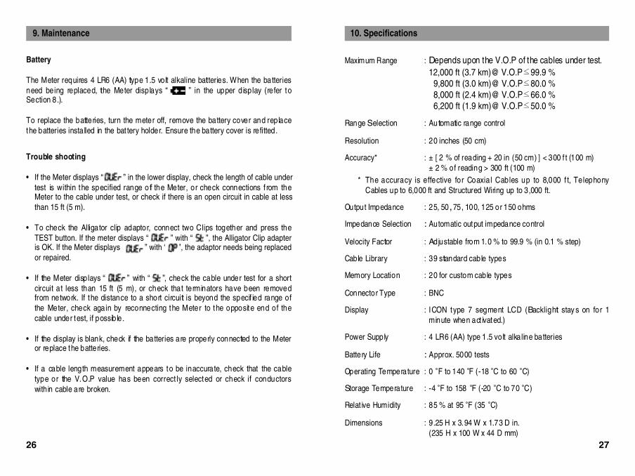
8.3 Enable or disable the auto-power-off mode
You can customize the required default sett ing between Enable and Disable settingsby pressing the POWER button for about 2 seconds during the button beingdepressed, when the Meter will display “ ” in the upper display and “ ” inthe lower display.
I f y ou want to dis able the auto- pow er-of f mode duri ng y our taki ngmeasurements, press the OK button.
If you want to enable the auto-power-off mode, press either the button or thebutton, when the Meter will display “ ” replacing “ ” in the lower
display, and then press the OK button to return to the auto-power-off mode.
Fig. 18
Fig. 19
24 25
8.4 Tone Generator mode
The Meter generates an oscillating (810 - 1100 Hz) tone, which is transmitteddown the cable under test and can be picked up with a standard tone probe (notsupplied) available in the marketplaces. This facilitates cable tracing. To selectTone Generator mode, turn the Meter off , then press the TONE button for morethan 1 second. The message “ ” will appear on the display. To resumenormal operation, press the EXIT button.
8.5 Line Voltage Detection mode
The Meter displays “ ” message and stops operation if line voltage of the cableunder test exceeds 6.5 V when the Meter is turned on.
Maximum Range : Depends upon the V.O.P of the cables under test.12,000 ft (3.7 km)@ V.O.P 99.9 %
9,800 ft (3.0 km)@ V.O.P 80.0 %8,000 ft (2.4 km)@ V.O.P 66.0 %6,200 ft (1.9 km)@ V.O.P 50.0 %
Range Selection : Automatic range control
R e s o l u t i o n : 20 inches (50 cm)
A c c u r a c y * : [ 2 % of reading + 20 in (50 cm) ] < 300 f t (100 m) 2 % of reading > 300 ft (100 m)
The accuracy is effective for Coaxial Cables up to 8,000 f t, TelephonyCables up to 6,000 ft and Structured Wiring up to 3,000 ft.
Impedance Selection : Automatic output impedance control
Velocity Factor : Adjustable from 1.0 % to 99.9 % (in 0.1 % step)
Cable Library : 39 standard cable types
Memory Location : 20 for custom cable types
Connector Type : B N C
D i s p l a y : ICON type 7 segment LCD (Backlight stay s on for 1minute when act ivated.)
Power Supply : 4 LR6 (AA) type 1.5 volt alkaline batteries
Battery Life : Approx. 5000 tests
Operating Temperature : 0 F to 140 F (-18 C to 60 C)
Storage Temperature : -4 F to 158 F (-20 C to 70 C)
Relat ive Humidity : 85 % at 95 F (35 C)
D i m e n s i o n s : 9.25 H x 3.94 W x 1.73 D in.(235 H x 100 W x 44 D mm)
10. Specifications
26 27
B a t t e r y
The Meter requires 4 LR6 (AA) type 1.5 volt alkaline batteries. When the batteriesneed being replaced, the Meter displays “ ” in the upper display (refer toSection 8.).
To replace the batteries, turn the meter off, remove the battery cover and replacethe batteries installed in the bat tery holder. Ensure the battery cover is refitted.
Trouble shooting
If the Meter displays “ ” in the lower display, check the length of cable undertest is within the specified range of the Meter, or check connections f rom theMeter to the cable under test, or check if there is an open circuit in cable at lessthan 15 ft (5 m).
To check the Alligator clip adaptor, connect two Clips together and press theTEST button. If the meter displays “ ” with “ ”, the Alligator Clip adapteris OK. If the Meter displays “ ” with “ ”, the adaptor needs being replacedor repaired.
If the Meter displays “ ” with “ ”, check the cable under test for a shortcircuit at less than 15 ft (5 m), or check that terminators have been removedfrom network. If the distance to a short circuit is beyond the specif ied range ofthe Meter, check again by reconnecting the Meter to the opposite end of thecable under test, if possible.
If the display is blank, check if the batteries are properly connected to the Meteror replace the batteries.
If a cable length measurement appears to be inaccurate, check that the cabletype or the V.O.P value has been correct ly selected or check if conductorswithin cable are broken.
9. Maintenance
The Meter contains statically sensitive devices and is not user serviceable. If a unitfails, or its protection has been impaired, it should not be used and sent for repairby suitably trained and qualified personnel.
New Meters are guaranteed for 1 year from the date of the user’s purchase.
For service requirements contact the distributor from whom the Meter was originallypurchased.
Repair and WarrantyW e i g h t : Approx. 16 oz (450 g)
P r o t e c t i o n : Ov erv ol tage protec tion against telephone networkvoltages (EN 60950 : 1999 Sec. 2.3)
S a f e t y : I E C 1010-1 : 2001
E M C : EN 61326 : 1997+ A 1 : 1998CE Cert ificated
![Time Domain Reflectometer MEGGER TDR2000 · There are four modes of operation to get “live” results, and these are: [L1] & [OFF] Trace is acquired from L1 only, internal balance](https://static.documents.pub/doc/80x56/5bac47c309d3f2c06d8cfe64/time-domain-reflectometer-megger-tdr2000-there-are-four-modes-of-operation-to.jpg)


