40
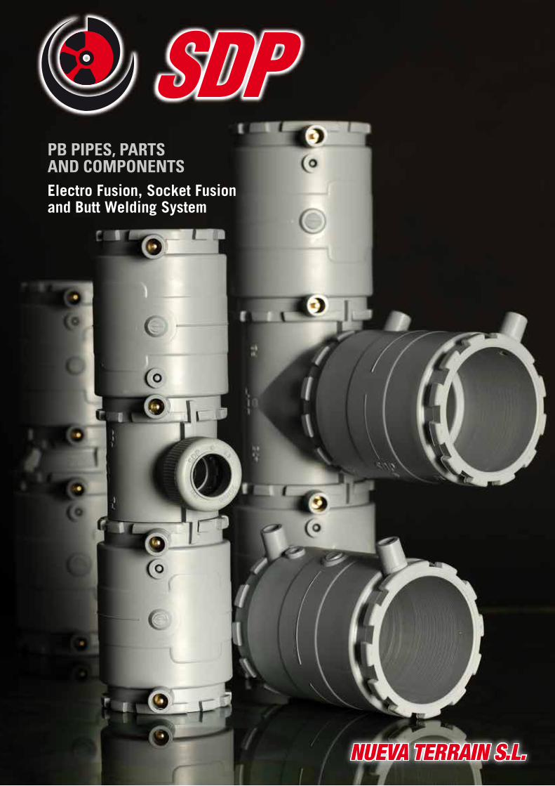
NUEVA TERRAIN S.L. NUEVA TERRAIN S.L. PB PIPES, PARTS AND COMPONENTS Electro Fusion, Socket Fusion and Butt Welding System
NUEVA TERRAIN S.L.NUEVA TERRAIN S.L.
PB PIPES, PARTS AND COMPONENTSElectro Fusion, Socket Fusion and Butt Welding System

TABLE OF CONTENTS
Electro Fusion System3
Socket Fusion10
Tools18
Technical Manual20
General Conditions39
As part of its on-going research programme, NUEVA TERRAIN, the Spanish
market leading manufacturer of PVC and Polybutylene (PB) parts and
components with Push-Fit and Socket Fusion ranges, has developed the
end part of the PB system- PB BUTT WELDING AND ELECTROFUSION.
This new line of products means that NUEVA TERRAIN can now offer a
widest range of systems on the market, all manufactured to the highest
quality standards.
The technical information, certification and other characteristics are set
out in detail in this brochure.

Electro Fusion System

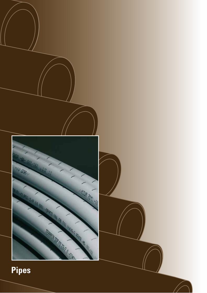
Pipes

5
STRAIGHT PIPESREFERENCE DIAMETER PIPE
WEIGHT kg.TOTAL PIPE LENGTH m.
THICKNESSmm.
MATERIAL
Classification according to classes : ISO 10508: Class 1/10 Bar – Class 2/10 Bar – Class 4/ 10 Bar – Class 5/8 Bar (Nominal pressure DIN 16969: PN 16).
5,80
5,80
5,80
5,80
5,80
5,80
5,8
6,8
8,2
10,0
11,4
14,6
5.783
8.033
11.582
17.690
23,23
37,90
PB
PB
PB
PB
PB
PB
63
75
90
110
125
160
TFC.058.063
TFC.058.075
TFC.058.090
TFC.058.110
TFC.058.125
TFC.058.160

Polybutylene “PB” Parts

7
B
A
D.N.
Electrofusion socket and butt welding fittings sold separately.
D.N.
A
D.N.
A
Electrofusion socket and butt welding fittings sold separately.
ELECTROFUSION SOCKETREFERENCE DIAMETER MATERIALUNIT WEIGHT
gramsA
FC7.001.063
FC7.001.075
FC7.001.090
FC7.001.110
FC7.001.125
FC7.001.160
63
75
90
110
125
160
211,0
282,0
442,0
680,0
1.180,0
-
PB
PB
PB
PB
PB
PB
116
128
144
160
180
201
45º ELBOWREFERENCE DIAMETER MATERIALUNIT WEIGHT
gramsFC6.005.063.045
FC6.005.075.045
FC6.005.090.045
FC6.005.110.045
FC6.005.125.045
63
75
90
110
125
190,0
282,6
447,0
765,0
1.037,0
PB
PB
PB
PB
PB
A
83,0
89,0
102,0
115,0
125,0
90º ELBOWREFERENCE DIAMETER MATERIALUNIT WEIGHT
gramsA
FC6.005.063.090
FC6.005.075.090
FC6.005.090.090
FC6.005.110.090
FC6.005.125.090
FC6.005.160.090
63
75
90
110
125
160
266,0
380,0
600,0
960,0
1.375,0
-
PB
PB
PB
PB
PB
PB
103,5
116,5
133,5
154,0
167,0
197,5
EQUAL TEEREFERENCE DIAMETER MATERIAL BUNIT WEIGHT
gramsA
FC6.010.063
FC6.010.075
FC6.010.090
FC6.010.110
FC6.010.125
FC6.010.160
63
75
90
110
125
160
290,0
600,0
803,0
1.359,0
1.833,0
-
PB
PB
PB
PB
PB
PB
103,5
116,5
133,5
154,0
167,0
197,5
207
233
267
307,5
334
395
A
D.N.
A 135°
ELECTRIC SOCKET TEEREFERENCE DIAMETER MATERIALUNIT WEIGHT
gramsFC7.010.063.003
FC7.010.075.003
FC7.010.090.003
FC7.010.110.003
63
75
90
110
407,5
658,0
1033,0
-
PB
PB
PB
PB
A
103,60
116,60
134,80
153,80
EN ISO 15876- 21,9 bar (in countries that are ruled by DIN 169691 – PN 16)
Electrofusion socket and butt welding fittings sold separately.
B
A
D.N
.

REDUCED TEEREFERENCE DIAMETER MATERIAL BUNIT WEIGHT
gramsFC6.013.090.063
FC6.013.110.063
90x63x90
110x63x110
600,0
854,0
PB
PB
119
132
A
242
258
Electrofusion socket and butt welding fittings sold separately.
A
B
d.n.
D.N.
Electrofusion socket and butt welding fittings sold separately always for smaller diameter.
REDUCED TEE TO PUSH FITREFERENCE DIAMETER MATERIAL BUNIT WEIGHT
gramsFC6.013.063.025 63x25x63 183,0 PB 65
A
176
Electrofusion socket and butt welding fittings sold separately.
D.N.
C
d.n.
A
B
E-FUSION REDUCED TEE TO PUSH FITREFERENCE DIAMETER MATERIAL BUNIT WEIGHT
gramsFC7.013.063.025
FC7.013.063.040
63x25x63
63x40x63
354,0
494,0
PB
PB
71
91
A
170
170
E-FUSION REDUCED SOCKETREFERENCE DIAMETER MATERIALUNIT WEIGHT
gramsFC7.002.125.110 125x110 1.055,0 PB
A
190
A
D.N.d.n.
d.n.
D.N
.
A REDUCED SOCKETREFERENCE DIAMETER MATERIALUNIT WEIGHT
gramsFC6.002.075.063
FC6.002.090.063
FC6.002.090.075
FC6.002.110.063
FC6.002.110.075
FC6.002.110.090
FC6.002.160.125
75x63
90x63
90x75
110x63
110x75
110x90
160x125
386,0
443,0
558,0
544,0
661,0
885,0
-
PB
PB
PB
PB
PB
PB
PB
A
138
146
152
154
160
168
245
8
A
B
EN ISO 15876- 21,9 bar (in countries that are ruled by DIN 169691 – PN 16) EN ISO 15876- 21,9 bar (in countries that are ruled by DIN 169691 – PN 16)

99
REDUCED SOCKET TO PUSH FITREFERENCE DIAMETER MATERIALUNIT WEIGHT
gramsFC6.002.063.025
FC6.002.063.032
FC6.002.063.040
FC6.002.063.050
63x25
63x32
63x40
63x50
117,0
139,0
253,0
289,0
PB
PB
PB
PB
A
106,0
112,0
118,0
113,8
A
B
D
A
B
C
D.N. d.n.
A
D.N.
A
FLANGE ADAPTERREFERENCE DIAMETER MATERIALUNIT WEIGHT
gramsA
FC6.032.063.001
FC6.032.075.001
FC6.032.090.001
FC6.032.110.001
FC6.032.125.001
FC6.032.160.001
63
75
90
110
125
160
139,0
205,0
309,0
465,0
702,0
-
PB
PB
PB
PB
PB
PB
98
104
112
120
140
180
FLANGE RINGREFERENCE DIAMETER MATERIAL BUNIT WEIGHT
gramsA
FC6.032.063.003
FC6.032.075.003
FC6.032.090.003
FC6.032.110.003
FC6.032.125.003
FC6.032.160.003
63
75
90
110
125
160
41,0
54,0
60,0
83,0
158,0
-
EPDM
EPDM
EPDM
EPDM
EPDM
EPDM
4
5
5
5
6
6
106
125
141
161
161
218
MALE-MALE SOCKET ADAPTER
D
BACKING FLANGE PN16
FC6.032.063.002
FC6.032.075.002
FC6.032.090.002
FC6.032.110.002
FC6.032.160.002
63
75
90
110 - 125*
160
940,0
1340,0
1.400,0
1.560,0
-
M 16 x 90 (4)
M 16 x 90 (4)
M 16 x 90 (8)
M 16 x 90 (8)
M 20 x 140 (8)
171
191
208
226
296
78
92
110
133
188
20
21
21
22
27
125
145
160
180
240
TORNILLOSREFERENCE DIAMETER UNIT WEIGHT grams
D.N.d.n.
A
REFERENCE DIAMETER MATERIALUNIT WEIGHT grams
A
FC6.031.063
FC6.031.075
FC6.031.090
63 - 2”
75 - 2 1/2”(F) - 3 ”(M)
90 - 3”(F)- 3 1/2”(M)
1.372,7
2.086,0
2.620,0
PB - METAL
PB - METAL
PB - METAL
155,0
161,0
169,0
Every reference must be acquired by his corresponding socket.
EN ISO 15876- 21,9 bar (in countries that are ruled by DIN 169691 – PN 16) EN ISO 15876- 21,9 bar (in countries that are ruled by DIN 169691 – PN 16)
*The flange ø110 is the same as for ø125

Socketfusion System
Pipes

12
STRAIGHT PIPES
REFERENCE DIAMETER PIPE WEIGHT kg.
TOTAL PIPE LENGTH m.
WALL THICKNES
S mm.TFC.058.016.025
TFC.058.020.020
TFC.058.025
TFC.058.032
TFC.058.040
TFC.058.050
TFC.058.063
•
•
•
•
•
•
•
16 (1)
20 (1)
25 (1)
32 (2)
40 (2)
50 (2)
63 (2)
2,2
2,3
2,3
2,9
3,7
4,6
5,8
551
737
928
1.508
2.378
3.654
5.783
5,80
5,80
5,80
5,80
5,80
5,80
5,80
MATERIAL
PB
PB
PB
PB
PB
PB
PB
[1] For pipes on straight stretches curvatures of a radius no less than 10 times the exterior diameter of the tube are permissible.[2] For lengths of pipes, it is permitted curves which radius is not less than 15 times the external diameter of the pipe.[3] Not less than 8 times of the external diameter of the pipe.
• AENOR certified pipes.
PIPES IN COILS
REFERENCE DIAMETER PIPE WEIGHT kg.
TOTAL PIPE LENGTH m.
WALL THICKNESS
mm.MATERIAL
TFC.100.016.025
TFC.050.016.025
TFC.050.020.020
TFC.036.025
•
•
•
•
16 (3)
16 (3)
20 (3)
25 (3)
2,2
2,2
2,3
2,3
9.800
4.900
6.355
5.760
PB
PB
PB
PB
100,00
50,00
50,00
36,00
Classification according to classes: ISO 10508: Class 1/10 Bar - Class 2/10 Bar - Class 4/10 Bar - Class 5/8 Bar - ( Nominal pressure according DIN 16969: PN 16)

Polybutylene “PB” Parts

14
PIPE SOCKETREFERENCE DIAMETER
D.N. x d.n.MATERIALUNIT WEIGHT
gramsFC4.001.016
FC4.001.020
FC4.001.025
FC4.001.032
FC4.001.040
FC4.001.050
FC4.001.063
16
20
25
32
40
50
63
6,0
7,0
12,5
22,5
38,5
67,5
125,0
PB
PB
PB
PB
PB
PB
PB
A
33,00
33,00
39,00
43,00
48,00
54,00
60,00
90º ELBOWREFERENCE DIAMETER
mm.MATERIALUNIT WEIGHT
gramsFC4.005.016.090
FC4.005.020.090
FC4.005.025.090
FC4.005.032.090
FC4.005.040.090
FC4.005.050.090
FC4.005.063.090
16
20
25
32
40
50
63
8,5
12,0
19,5
36,0
64,0
114,5
219,0
PB
PB
PB
PB
PB
PB
PB
A
25,0
28,0
32,0
38,0
44,0
51,0
62,0
45º ELBOWREFERENCE DIAMETER
mm.MATERIALUNIT WEIGHT
gramsFC4.005.032.045
FC4.005.040.045
FC4.005.050.045
32
40
50
-
-
-
PB
PB
PB
A
29,0
33,0
37,0
REFERENCE DIAMETER D.N. x d.n.
MATERIALUNIT WEIGHT grams
A
M-F REDUCER
FC4.002.020.016
FC4.002.025.016
FC4.002.025.020
FC4.002.032.025
FC4.002.040.025
FC4.002.040.032
FC4.002.050.032
FC4.002.050.040
FC4.002.063.040
FC4.002.063.050
20x16
25x16
25x20
32x25
40x25
40x32
50x32
50x40
63x40
63x50
5,5
6,5
6,5
12,5
18,9
20,0
40,5
40,5
56,5
68,0
PB
PB
PB
PB
PB
PB
PB
PB
PB
PB
30,00
33,00
33,00
40,00
46,00
42,00
52,50
55,00
59,00
58,00
D.N.
A
A
D.N. d.n.
A
D.N.
EQUAL TEEREFERENCE DIAMETER
mm.MATERIALUNIT
WEIGHT grams
FC4.010.016
FC4.010.020
FC4.010.025
FC4.010.032
FC4.010.040
FC4.010.050
FC4.010.063
16
20
25
32
40
50
63
11,5
16,0
25,0
47,0
83,0
144,0
280,0
PB
PB
PB
PB
PB
PB
PB
A
50,0
56,0
64,0
76,0
88,0
102,0
124,0
B
25,0
28,0
32,0
38,0
44,0
51,0
62,0
D.N.
A
B
D.N
.
A

15
FC4.013.020.016
FC4.013.025.016
FC4.013.025.020
FC4.013.032.016
FC4.013.032.020
FC4.013.032.025
FC4.013.040.025
FC4.013.050.025
FC4.013.063.025
20x16x20
25x16x25
25x20x25
32x16x32
32x20x32
32x25x32
40x25x40
50x25x50
63x25x63
18,0
26,0
24,0
44,0
42,0
44,0
77,0
132,0
255,0
PB
PB
PB
PB
PB
PB
PB
PB
PB
56,0
64,0
64,0
76,0
76,0
76,0
88,0
102,0
124,0
28,0
32,0
32,0
38,0
38,0
38,0
44,0
51,0
62,0
REDUCED TEEREFERENCIA DIAMETER
mm.MATERIALUNIT
WEIGHT grams
A B
d.n.
A
D.N.
B
FC4.019.040.025
FC4.019.050.025
40x25x40
50x25x50
75,0
128,0
PB
PB
88,0
102,0
57,0
63,5
REDUCED TEE (FxMxF) REFERENCIA DIAMETER
mm.MATERIAL A B
d.n.
A
B
D.N.
THREE OUTLET MANIFOLDREFERENCIA DIAMETER
mm.MATERIAL
FC4.017.025.016 25x16x16x16x25 50 PB
A
153,0
B
28,0
C
32,0
D
45,0
E
31,0
F
20,0
d.n.D CE
A
BF D.N.
D.N.
TWO OUTLET MANIFOLDREFERENCIA DIAMETER
mm.MATERIAL
FC4.015.025.016 25x16x16x25 34,5 PB
A
108,0
B
28,0
C
32,0
D
45,0
E
31,0
F
20,0
d.n.D C
F D.N.
A
E
D.N.
B
FOUR OUTLET MANIFOLD REFERENCIA DIAMETER
mm.MATERIAL A B C D E F
FC4.018.025.016
FC4.018.032.016
25x16x16x16x16x25
32x16x16x16x16x32
65,5
93,0
198,0
200,0
PB
PB
28,0
32,0
32,0
35,0
45,0
45,0
31,0
30,0
20,0
25,0
d.n. D CEA
BF D.N.
D.N.
UNIT WEIGHT grams
UNIT WEIGHT grams
UNIT WEIGHT grams
UNIT WEIGHT grams

FC4.041.016
FC4.041.020
FC4.041.025
FC4.041.032
FC4.041.040
FC4.041.050
FC4.041.063
16
20
25
32
40
50
63
4,0
6,5
9,0
15,5
33,0
57,0
107,0
PB
PB
PB
PB
PB
PB
PB
22,0
24,0
28,0
32,0
38,0
44,0
50,0
END CAPREFERENCE DIAMETER
mm.MATERIALUNIT WEIGHT
gramsA
16
ADAPTOR UNION SOCKET- FEMALE THREAD
-
-
-
-
REFERENCE DIAMETERmm.
MATERIALUNIT WEIGHT grams
32x1"
40 x 1/4"
50 x 1/4"
63 x 1/2"
-
361,0
498,0
1.876,0
Brass
Brass
Brass
Brass
FC6.033.032
FC6.033.040
FC6.033.050
FC6.033.063
ADAPTOR UNION SOCKET - MALE THREADREFERENCE DIAMETER
mm.MATERIALUNIT WEIGHT
grams32x1"
40 x 1/4"
50 x 1/4"
63 x 1/2"
-
407,0
569,0
-
Brass
Brass
Brass
Brass
FC6.035.032
FC6.035.040
FC6.035.050
FC6.035.063
EN ISO 15876- 21,9 bar (in countries that are ruled by DIN 169691 – PN 16)
SOCKET FUSION REDUCED SOCKETREFERENCE DIAMETER
mm.MATERIALUNIT WEIGHT
gramsFC4.029.016.015
FC4.029.020.022
16x15
20x22
7,0
10,0
PB
PB
A
47,5
47,5
A
d.n.D.N.
FC4.030.016
FC4.030.020
FC4.030.025
16x1/2"
20x1/2"
25x3/4"
80,5
128,0
175,5
Brass-PB
Brass-PB
Brass-PB
41,0
41,0
49,5
TRANSITION FROM SOCKET FUSION(M) TO THREADED (F)REFERENCE DIAMETER
mm.MATERIALUNIT WEIGHT
gramsA
A
D.N.d.n.
FC4.031.016
FC4.031.020
FC4.031.025
16x1/2"
20x1/2"
25x3/4"
110,0
155,0
226,5
Brass-PB
Brass-PB
Brass-PB
52,0
52,0
62,5
TRANSITION FROM SOCKET FUSION(M) TO THREADED (M)REFERENCE DIAMETER
mm.MATERIALUNIT WEIGHT
gramsA
A
D.N.d.n.
D.N.
A
17
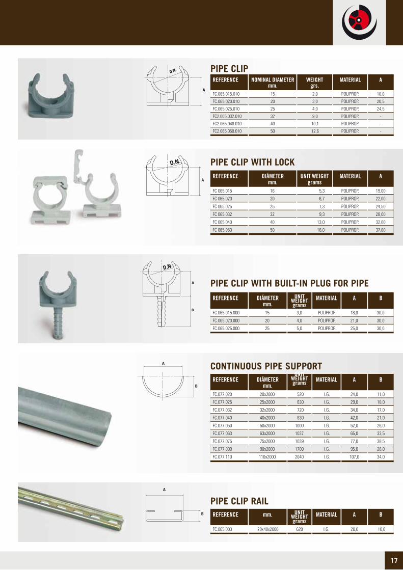
CONTINUOUS PIPE SUPPORTREFERENCE DIÁMETER
mm.MATERIAL A B
FC.077.020
FC.077.025
FC.077.032
FC.077.040
FC.077.050
FC.077.063
FC.077.075
FC.077.090
FC.077.110
20x2000
25x2000
32x2000
40x2000
50x2000
63x2000
75x2000
90x2000
110x2000
520
630
720
830
1000
1037
1039
1700
2040
I.G.
I.G.
I.G.
I.G.
I.G.
I.G.
I.G.
I.G.
I.G.
24,0
29,0
34,0
42,0
52,0
65,0
77,0
95,0
107,0
11,0
18,0
17,0
21,0
26,0
33,5
38,5
26,0
34,0
UNIT WEIGHT grams
PIPE CLIP RAILREFERENCE mm. MATERIAL A B
FC.065.003 20x40x2000 620 I.G. 20,0 10,0
UNIT WEIGHT grams
REFERENCE NOMINAL DIAMETER mm.
MATERIALWEIGHTgrs.
A
PIPE CLIP
POLIPROP.
POLIPROP.
POLIPROP.
POLIPROP.
POLIPROP.
POLIPROP.
18,0
20,5
24,5
-
-
-
FC.065.015.010
FC.065.020.010
FC.065.025.010
FC2.065.032.010
FC2.065.040.010
FC2.065.050.010
2,0
3,0
4,0
9,0
10,1
12,6
15
20
25
32
40
50
FC 065.015
FC 065.020
FC 065.025
FC 065.032
FC 065.040
FC 065.050
16
20
25
32
40
50
5,3
6,7
7,3
9,3
13,0
18,0
POLIPROP.
POLIPROP.
POLIPROP.
POLIPROP.
POLIPROP.
POLIPROP.
19,00
22,00
24,50
28,00
32,00
37,00
PIPE CLIP WITH LOCKREFERENCE DIÁMETER
mm.MATERIALUNIT WEIGHT
gramsA
D.N.
A
REFERENCE DIÁMETERmm.
MATERIALUNIT WEIGHT grams
FC.065.015.000
FC.065.020.000
FC.065.025.000
15
20
25
3,0
4,0
5,0
POLIPROP.
POLIPROP.
POLIPROP.
A
18,0
21,0
25,0
B
30,0
30,0
30,0
PIPE CLIP WITH BUILT-IN PLUG FOR PIPE
D.N.
A
B
A
B
A
B

Tools

19
PIPE CUTTERREFERENCE DIAMETER UNIT WEIGHT
Kg.FC 078.050.127 50 a 125 1,63
ELECTROFUSION MACHINE (MANUAL, OPTIC READER)REFERENCE DIAMETER UNIT WEIGHT
Kg.FC 7.090 UNIVERSAL DE 8 - 48V 20,0
MEASUREMENTS
116 x 220 x 119
PIPE PEELERREFERENCE DIAMETER UNIT WEIGHT
Kg.FC7.092 50 a 160 4,20
PIPE CUTTER (Ø TO 28 mm.)REFERENCE DIAMETER MATERIALWEIGHT
grs.FC.074 0 a 28 294 METALLIC
PIPE CUTTER (Ø TO 28 mm.)REFERENCE DIAMETER MATERIALWEIGHT
grs.FC.073 0 a 28 110 PLASTIC

Technical Manual

15921
Nueva Terrain works continuously to offer its clients and the market
integral solutions for the widest variety of facilities. The company
has now developed its own, homologated, comprehensive, large
diameter water supply system. After conducting lengthy research
and performing thorough tests, NUEVA TERRAIN is now
manufacturing and supplying its own polybutylene system, with
diameters ranging between 63 and 160 mm. This represents a
significant technological innovation.
This new system is compatible with standard tools found in other
types of installations, such as gas and hot water supply. This enables
it to contribute a unique solution in the sector, which is compatible
with the equipment and joint tools already available in the market.
The SDP Terrain Polybutylene catalogue now includes diameters of up to 160 mm, and comes with a range of accessories compatible
with the two standard joint systems: butt joints and 40 volt electro fusion joints. In line with the strategy on which our company has
been founded, these are manufactured using the best material on the market. Polybutylene, with a standard, simple and reliable joint
system ensures a product with unbeatable qualities for these applications. The system is therefore classified as Class 2 with a working
pressure up to 10 bar according to ISO 10508, which is the highest possible for this type of installation. This means that the system
is designed to withstand continuous operating temperatures of 70ºC and a pressure of 10 bars, for a useful life of 50 years, with
security coefficients defined by international standards. We have chosen an optimum system, to provide our customers with installations
that meet increasingly demanding construction standards, particularly those governing resistance to treatments set out in the law
for the prevention of Legionnaires disease. When you choose the Terrain SDP system, you can be sure you are installing a product
that provides optimum performance according to the demands of the standards for different products used in cold and hot water,
heating and cooling systems.
In addition to the above, the technical and commercial support of
our staff and from a company with more than 40 years in the market,
and the comprehensive nature of our research, development, design,
manufacturing control process for all our products mean support
and guarantees for Nueva Terrain customers. The safety and
reliability of our system are guaranteed. Our customers’ questions,
enquiries or problems are immediately referred to our technical
department, which has developed and manufactured the product,
making them the right experts to provide you with the answers and
solutions you need.
Introduction

22
Our company’s history, professionalism and approachability are essential elements of our desire to collaborate with the market we supply. This direct relationship enables us to continue to grow guided by our customers' demands and suggestions which will be more than happy to answer. It is in line with this philosophy that this new system is launched, as well as a multitude of other products and solutions that make up the largest product catalogue in our sector.
This large, 160 mm diameter system has been chosen to enable all types of installations to be supplied. No larger dimensions have been considered on the basis that these would cause the installation to become excessively dependent on a single supplypoint, so in these cases designs involving multiple rings of smaller diameters have been selected.
The system characteristics, according to the bivalence of the joint systems and the materials used for manufacturing the system are summarised below:
• Versatile: Adapts to different joint systems and solutions for different types of system existing on the market.
• Standard: The tools required for both types of joint are on the market and common to the other systems existing on the market.
• Quality: The whole system is designed, produced, tested and certified according EN ISO 15876.
Application and characteristics
The characteristics of the pipes and fittings manufactured in Polybutylene (PB), a unique, homogeneous plastic material, make it suitable for piping an extremely wide range of liquids. Its inert nature makes its impervious to attacks from weak acids, alkalines and dissolvents, making it a suitable substitute for metal installations that become oxidised by such substances. For further information, see the table which sets out resistance to chemical agents or contact our technical department, which will be able to answer any questions you might have about piping fluids other than water.
The aforementioned inert quality of this materials also means that the useful life of PB installations is far lengthier than those of metal, especially in the case of hard water.
With regard to the above, PB is excellent in terms of hygiene, and holds certificates for carrying drinking water in many countries. The organoleptic and migration tests conducted satisfy international requirements, as well as the European Directive on Water Quality for human consumption, which was included in Spanish Law by the passing of Royal Decree Law 140/2003, of 7 February.

15923
• Market leader in Resistance: The Terrain SDP system is defined as Class 2 /10 bar pressure. This is 10 bar pressure designed for continuous temperature of 70ºC and a useful life of 50 years. This classification is the highest included in the standards and makes it the market leader, thanks to the excellent characteristics of the material (polybutylene) and the specific design of the unions to withstand these conditions.
• Complete, homogeneous range: The large diameter Terrain SDP water supply system is manufactured entirely in polybutylene, the best performing material among those homologised. With a wide range of accessories and pipes for a large variety of construction solutions, our catalogue is constantly updated to meet the changing demands of the market.
• Diverse, integrated applications: The comprehensive Nueva Terrain system, which includes Push-Fit joint systems and socketfusion for smaller diameters, makes it the best available on the market, guarantees an installation from a sole provider and a single material. This makes it ideal for public buildings, hospitals, hotels, residential homes, schools, sports and religious installations... as well as industrial facilities and boats. The range and its characteristics make it ideal for cold and hot water, centralised air conditioning, heating and cooling systems.
• Low elasticity module: Polybutylene has a lower elastic module than the other materials for this application. This makes it the most flexible, and beyond the advantages this means for handing it on site, it has also excellent qualities: more resistance to impact, the generation of forces on dilatations are very low (in specific situations, even without the need to construct blows), resistant to freezing and reduction of water hammering effect.
• Low thermal conductivity coefficient: This means less heat loss and less likelihood of condensation on the outer surface of the pipes.
• Hygienic: Organoleptic and migration studies in several European institutes prove that it has no effects on water for human consumption. The absence of corrosion and lime scale deposits means water is piped in optimum conditions.
• Low noise transmission: The material's aforementioned elastic module makes these pipes excellent noise insulators, which leads to more comfortable installations.
• Legionnaire’s disease: Polybutylene is the ideal material for for fighting against Legionnaire’s disease. Because of its resistance to chemical substances and high temperatures, the treatments demanded by Royal Decree Law 865/2003 for disinfection can be applied without any risk of damaging the installations. The absence of corrosion in plastic materials hinders the formation of a bio-layer.
• Own development and manufacturing: New Terrain designs and manufactures its systems entirely at its own production plants, and has a mechanical workshop for designing, manufacturing and maintaining the moulds and other production tools, which guarantees the close tolerances of our product throughout the whole process of its manufacture.

24
Table of the characteristics of polybutylene (PB1)PROPERTIES STANDARD VALUE UNIT
External diameter
Wall thickness
Colour
Density
Fluid index ( Melt Flow Index)
Black carbon content
ESCR (50ºC/10 % solution lgpal C0603)
Tensile Steghth at vield
Tensile Steghth at break
Tensile modulus
Enlongation at break
Longitudinal Retraction
Hardness
Resistance to impact (Notched)
Thermal expansion coefficient
Thermal conductivity ( 30 - 70ºC)
Fusion temperature
Vicat softening temperature
Vitria transition temperature
Hydrostatic resistance to rupture
Internal hydrostatic pressure
Speed of sound
Toxicity
Bacteriological Analysis
EN ISO 15876
EN ISO 15876
ISO 1183
ISO 1133 – 190ºC/2,16 Kg
--
ASTM D1693
ISO R 527
ISO R 527
ISO 178
ISO R 527
EN 743
ISO 868
ISO 180
ASTM D696
ASTM C177
DSC
ISO 306
DMTA
EN 921
EN ISO 9080
-
0,939
0,35
<0.1
15000 h
Without failure
20,4
36,5
450
300
< 2
60
20
7
1,3 · 10-4
0,19
130
120
-16
g/cm3
dg/mg
%
H
MPa
MPa
MPa
%
%
Shore D
KJ/m2 a 20ºC
KJ/m2 a 0ºC
m/mK
W/mK
ºC
ºC
ºC
See EN ISO 15876-2; Point 6.2.1
See EN ISO 15876-2; Point 6.2.2
Grey – RAL 7001
See EN ISO 15876-2 – Point 7
See EN ISO 15876-2 – Point 4.2
620 m/s
Non-toxic – According to organoleptic and migration studies at several Independent Institutes
KIWA (Holland) and the German Association of water and Gas
(GVGW), Technical Guide W270)
There is no growth of micro-organisms after 6 months of immersion. The material satisfies
the requirements.
System Characteristics Table
Table of pipe characteristics for TERRAIN SDP fusion systems.
TYPE OF APPLICATIÓNIN ISO 15876
Class 2(70ºC, 10 bars, 50 years, C 1,5)
Definition of C: Overall Service Coefficient (Safety Factor).Definition of PN: Nominal pressure at 20oC bcC for 50 years with a safety factor of 1.25. ( This definition is not used anymore in the EN ISO 15876)Definition of SDR: Standard dimensional ratio (OD /SDR=> approx. thickness).SDR 11: includes values of diameters from 25 to 160.
EXTERIOR DIAMETER MM mm 16 20 25 32 40 50 63 75 90 160
2,2
11,6
7,4
3,2
34,5
2,3
15,4
9
4
27,2
4,6
40,8
11
5
21,8
3,7
32,6
11
5
21,8
2,9
26,2
11
5
21,8
2,3
20,4
11
5
21,8
5,8
51,4
11
5
21,8
6,8
61,4
11
5
21,8
8,2
73,6
11
5
21,8
14,6
130,8
11
5
21,8
3
5,8
50
100
3
5,8
50
3
5,8
36
---
5,8
---
---
5,8
---
---
5,8
---
---
5,8
---
---
5,8
---
---
5,8
---
---
5,8
---
---
5,8
---
125
11,4
102,2
11
5
21,8---
5,8
---
Wall Thickness
Interior tube diameter
SDR
Pipe Serie
PN (bar)
Length in straight stretches
Length in Coils
mm
mm
110
10,0
90,0
11
5
21,8
m
m
m
m

15925
The joints
The material used for manufacturing the pipes and accessories is homogeneous, because polybutylene is injectable, and therefore the parts are made of the same material as the pipes. Polybutylene is a thermoplastic suitable for heat fusion of pipe and part, and can therefore be welded using thermo fusion, electro fusion and butt joint welding techniques. These two latter have been chosen for constructing the Terrain SDP large dimension system. They are simple, standard techniques that provide excellent, safe joints.
Connections to external networks are created by flange joints (PN16). This system ensures compatibility and enables easy, quick joining.
For installations with joints that can be made on the ground on in accessible positions, butt joint welding is very reliable and economic. To the contrary, when the joint must be located in an inaccessible or complex spot for typical butt welding joint tools to be used, the electro fusion technique should be chosen, as this allows cold assembly and subsequent joining by the application of an electrical current.
The characteristics of electro fusion joints are as follows:
• Fusion on the external walls of the pipe and electro fusion fitting, with electrical resistance on the inner surface, to ensure heat transmission among the parts to join the embedded resistance more efficiently.
• Standard fusion at 40 V by machine transformer, which avoids the hazards of electrical contact when handling joints, as well as ensuring stable tension regardless of the electrical source on the site.
• Simple, reliable joint which needs no more than a scrape or a cleaning of the joint to fuse and ensure the penetration length of the tubular part of the electro fused opening.
• Joint presented cold on site, and then created remotely using the electro fusion machine, which forms a simple, secure joint in even the most inaccessible of conditions.
• Automatic compensation of the energy contributed to the fusion according to the actual environmental temperature at the time of the joint, which ensures stable, even fusion regardless of environmental conditions.
With regard to the butt weld joint, the following aspects are significant:
• Parts joined must be of equal wall thickness, which results in a final installation equivalent to a prolonged pipe, with the consequential absence of reductions in diameter and additional stress on the joint.
• Simple, reliable joint, as there is no dependence on external factors.
• Economical, suitable joint for welding in workshops or in accessible situations.
• Safe and secure; The Butt Welding assembly technology is one of the most experienced type of unions in plastic piping systems so far. This type of unions has been done since more than 40 years and many of them are still working.The best proof is the fact that this type of unions is chosen for gas pipelines and chemical - industrial applications too. Laboratory tests shows that the pipe burts always first, before the Butt Welding union get damaged. The main difference to Socket Fusion is that Butt Welding unions must be made by machine.

Electro fusion jointing
• Qualified staff for jointing The joints must be made by staff training in electro fusion welding techniques with practical knowledge of the use of the available welding machinery.
• Welding equipment It is essential that homologated machines be used, capable of delivering the voltage and output required. It is recommended that machines used meet the requirements set out in standard DVS 2208.
• Steps-by-step instructions:
26
Cut the tube perpendicularly to its axis, to create a section which is as even as possible.1
Electro fusion jointing
Ream and clean the tube and the lower part of the coupler.2

15927
After 24 hours has past since creating the last joint, you can proceed with the hydraulic test on the installation.
11
The fusion gauge will enable you to check the installation is ready quickly.10
Once the fusion is complete, wait for the cooling time indicated in the parameters table, before continuing to handle the installation.
9
During the fusion process, stay at least one metre away from the fusion zone and do not handle the installation.8
Accept the settings read and start the fusion process.
7Using the optical reader, read the bar codes on the coupler.
6
Connect the electric terminals of the electro fusion machine to the coupler.
5Insert the tube as far as the mark.4
Using the marks on the tube, mark off the penetration length of the tube.3

28
Recommendation
• It is very important to ensure that all the joint surfaces are clean. The presence of drops of water, grease or any other element on the joint surface can cause a faulty joint.
• It is recommended you check that the gap between the tube and the coupler is acceptable. Very large gaps leave spaces in the joint that are detrimental to the joining process. This gap can be controlled during the reaming process and when aligning the coupler and the tube.
• It is recommended that correct alignment be achieved between the tube and part with the coupler. Angular misalignment may cause a faulty joint. According to DVS standards at 300 mm from the join, the misalignment of the tube must be no more than 1mm. The gap between the tube and the coupler must be even throughout its circumference.
• When the joint is finished, it is very important to comply with the cooling time stated. Handling the installation before the joint has cooled may damage the internal welding performed.
DIAMETER PENETRATION LENGTH
ELECTRICAL RESISTANCE
FUSION TIME SECONDS
COOLING TIME
mm mm Ohms Seg min
* All the active elements of the NUEVA TERRAIN electro fusion system have a bar code label where all the information needed to create the joint is stored.• E-Fusion reduced socket
Electro fusion jointing parameters
63
75
90
110
125 - 110•
125
160
58
64
72
80
90 - 80
90
100
15
15
15
15
15
15
15
2.9
1.4
2.2
1.0
1.2
1.3
2.0
110
110
160
220
310
345
780


30
Butt Welding Joints
• Qualified staff for joining
The joints must be made by staff training in butt joint welding techniques with practical knowledge of the use of the available welding machinery.
• Welding equipment
It is essential that homologated machines be used, capable of reaching and maintaining the temperature required for butt welding the SDR II tubes to 160 mm. It is recommended that machines meeting the requirements set out in standard DVS 2208 be used.
• Diagram of butt welding jointing process
The pressure value indicated in the previous diagram corresponds to the pressure that must be reached on the faces of the welded joint (part against part). According to the machine used to make the joint and the dimensions of the fittings to be joined, it will be necessary to calculate the force or pressure settings required by each machine, to achieve the pressure indicated in the diagram in the part contact zone.
The attached data tables set out the force values to be applied in the case of manual pressure joints (mechanical). In the case of hydraulic machines, the pressure to apply in the cylinder will depend on the diameter.
• Butt welding jointing settings
TubePB SDR 11
Sec.mm2
0.1 N/mm2
F1N
TOseg
Welding strand
mmT1sec
0.01 N/mm2
F2N
T2sec
T3sec
0.1 N/mm2
F3N
T4min
TempºC
*HC : Until welding strand is made.
Butt Welding Joints
Ø63 x5.8
Ø75 x6.8
Ø90 x8.2
Ø110 x10
Ø125 x11.4
Ø160x14.6
1042
1457
2107
3142
4069
6669
104
146
211
314
407
667
HC*
HC*
HC*
HC*
HC*
HC*
0.5
0.5
1
1
1
2
55
60
70
80
85
100
11
15
21
32
41
67
6
6
7
7
8
10
10
10
11
11
12
16
104
146
211
314
407
667
8
9
10
12
14
16
260
260
260
260
260
260
Pressure
Creating welding strand
Heating CoolingJoint
Time
Chan
ge
T0 T1 T2 T3 T4
0.1 Nmm2
0.01 Nmm2

15931
Place the tubes or parts to join in the vices of the welding machine.1
• Step-by-step instructions
Remove the buffing tool and clean away any remaining shavings.4
Clean any dirt from the faces and nearby areas. Place the buffing tool between the faces and start the machining process.
3
Check that the wall thickness of both parts is equal.Close the clamps and check that the tubes/parts and aligned, putting their faces together with the pressure device. •The maximum permitted misalignment is 10% of the thickness of the wall.
2
< 10% of pipe wall thickness
32
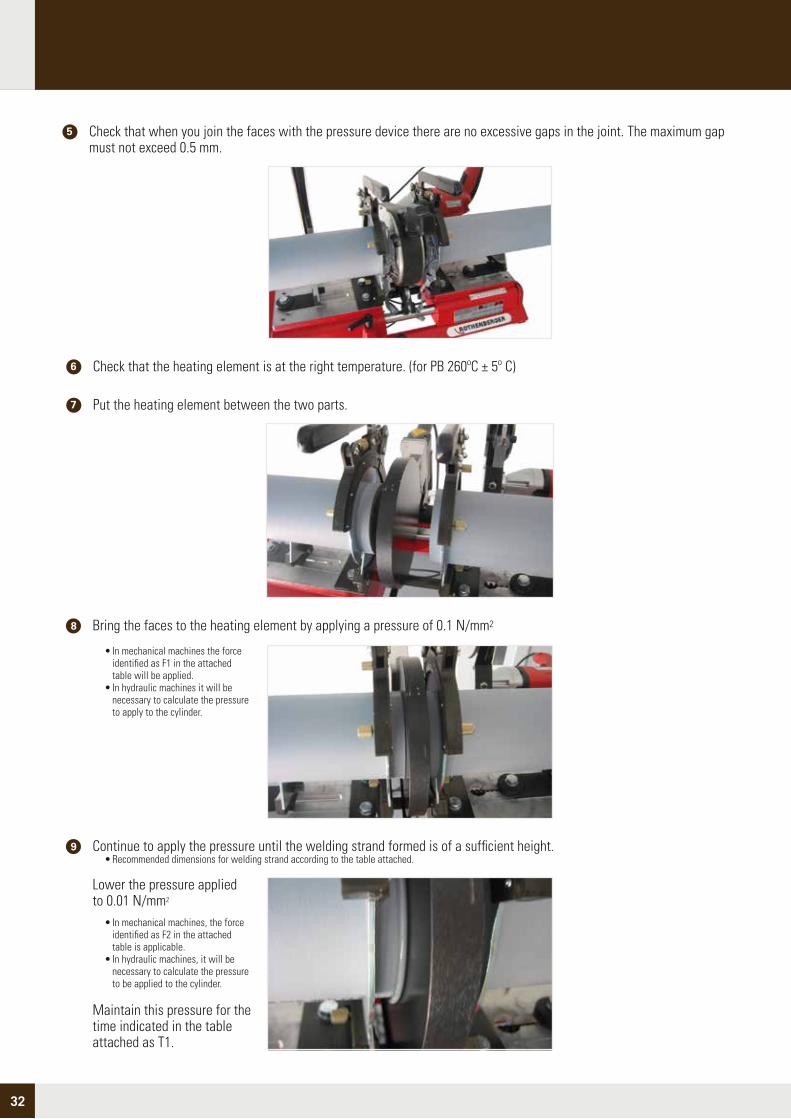
Check that when you join the faces with the pressure device there are no excessive gaps in the joint. The maximum gap must not exceed 0.5 mm.
5
Check that the heating element is at the right temperature. (for PB 260ºC ± 5º C) 6
Put the heating element between the two parts.7
Maintain this pressure for the time indicated in the table attached as T1.
Lower the pressure applied to 0.01 N/mm2
• In mechanical machines, the force identified as F2 in the attached table is applicable. • In hydraulic machines, it will be necessary to calculate the pressure to be applied to the cylinder.
Continue to apply the pressure until the welding strand formed is of a sufficient height. • Recommended dimensions for welding strand according to the table attached.
9
Bring the faces to the heating element by applying a pressure of 0.1 N/mm28
• In mechanical machines the force identified as F1 in the attached table will be applied. • In hydraulic machines it will be necessary to calculate the pressure to apply to the cylinder.

33
Although the joint is now finished, it is recommended you wait for approximately one hour for the weld to cool down before starting to handle the pieces welded.
15
Release the pipe clamps and remove the parts from the machine.14
Separate the faces of the heating element and withdraw. • It is recommended this operation be carried out as quickly as possible, in accordance with the time recommended (T2 in the attached table). • Before removing the heating element, check that it is not adhered to the faces of the pieces to avoid damaging the welding strand.
10
Put the faces together to start joining11
Increase the pressure during the time T3 to reach 0.1 N/mm2
• In mechanical machines the force called F3 in the table attached is applied •In hydraulic machines it will be necessary to calculate the pressure to apply to the cylinder.
12
Maintain this pressure for the time indicated in the table attached as T4.13
Before carrying out a pressure test on the installation, you must wait 24 hours.16
• Aspects to take into consideration
• After welding, the joint zone should appear as a double welded rectangular-shaped strand along the circumference, whose intermediate zone (valley) is always higher than the outside face of the parts. (see figure)
• In the case of carrying out welding outdoors, it is recommended the joint be protected from adverse climate conditions (rain, snow, wind...) which may cause inadmissible variations in the welding temperature reached.
> 0 mm

34
Joints with Flange
• Step-by-Step Instructions
Important: The face of the flange face outwards to allow the bolt nuts to be installed.
Make sure you have all the parts you need to assemble the joint.1
Insert the flange into the flange holder with the flat part facing towards the outside of the joint.2

35
3 Place the joint on the flat part of the flange holder.
Recommendations:
• It is very important to comply with the tightening torque of the bolts. Excessive tightening could damage the joint. • Never apply grease or lubricant to the joint.• The Nueva Terrain flange joint system is designed to be installed with its original components: flange holder, flange and flange joint. The use of other components may lead to unsatisfactory joints.
5 If the installation is to be continued with electro fusion joints, insert the coupler in the flange holder. The coupler must be fitted at the end of the process, because it will not allow the flange holder to pass through.
4 Assemble the parts with the joint against the join to be created. Position the bolts with their corresponding nuts and tighten evenly.
Important: Do not place the coupler before the flange, as it will then be impossible to insert it and it will be rendered useless.
NOMINAL DIAMETER (ext)
TIGHTENING TORQUE (Nm)
BOLT No. BOLTS PER FLANGE
63
75
90
110
125
160
30
35
40
45
50
60
M 16 x 80
M 16 x 80
M 16 x 90
M 16 x 90
M 16 x 100
M 20 x 140
4
4
8
8
8
8

36
Socket Fusion Assembling
The assembly
Joints must be created according to the instructions in our “Instruction Manual for assembling the PB Thermo fusion system”. Here is a summary of the steps to be followed:
The tube and the part to be thermo-welded must be of the same diameter and material.1
2
The tube and the part must remain in the oven for the time stipulated for each diameter, indicated as the heating time in table 1. This time period starts once the tube and the part are entirely inside the ovens.
4
TABLE 1 PARAMETERS FOR WELDING BY SOCKET FUSION IN PB.
TUBE DIAMETER (mm.)
ND
THICKNESS OF TUBE
WALL E (mm.)
HEATING TIME
(Seconds)
LENGTH WELD L (mm.)
16
20
25
32
40
50
63
2,2
2,3
2,3
2,9
3,7
4,6
5,8
15
15
18
20
22
25
28
5
6
6
10
14
18
22
MAINTENANCE TIME
(Seconds)
COOLING TIME
(Minutes)
15
15
15
20
20
30
30
2
2
2
4
4
4
6
To ensure that the tubular part penetrates the mouth of the piece to the correct depth, a mark is made on the tube using a marker pen or wax pencil with the help of template Reference FC 4070. The tube is then positioned on the mark that corresponds to the diameter of the tube being used. This template has marks (windows or perforations) for the entire range of measurements manufactured. This mark will be visible when next to the burr produced by the harrow of the weld.
To correctly carry out the weld, start by making a perpendicular cut in the tube. Then put the end of the tube and the mouth of the piece simultaneously into the oven (male and female) corresponding to their diameter, ensuring the machine is at the right temperature at that moment (for PB 260ºC ± 10º C)
3

37
Immediately after removing the tube and the part from the ovens these must simultaneously be joined. Do not twist the parts at all while making the join. The pieces must be inserted axially and flexion is only permitted to achieve better alignment.
Once the tube is inserted in the piece, the time period set out in table 1 as the maintenance time must be observed. This time is considered to start when the tube has been totally inserted until the weld has been established. This is done by exerting slight axial pressure, similar to that used to insert the part, during the time indicated in table 1, to avoid the tendency for the part to come out.
The cooling time is considered the space of time between the end of the thermo welding of the joint (without including the maintenance time) until the beginning of the next weld on the same part or tube being worked on, indicated in table 1.
The utmost care must be taken in this thermo fusion process, to ensure the tube is correctly aligned when inserted in the part to which it is to be joined. The tubes must be cut perpendicular to their axis and these must be free of any waste material or residue caused by cutting.
The surfaces to be welded on the tube and part must both
be cleaned. This should be done using absorbent paper, without dust threads and slightly moistened in an ethyl alcohol based detergent (for example technical alcohol 94%), which is free of greases and oils.
Tubes of 16 and 20 mm diameter do not need champhering or bevelling. Bevelling is recommended for tubes of 25, 32 and 40 mm in diameter. For tubes with a diameter of 50 and 63 mm bevelling is obligatory.
One hour after the final weld, the installation is ready for hydraulic testing, in accordance with the applicable standards and regulations.
5
6
Very important note: Never mix materials of different classes or composition, as they are not
compatible (example: PB-PP, etc).

38
Standards and tests
The TERRAIN SDP Polybutylene system for carrying cold and hot water and heating in large diameters complies with European and International Standard UNE EN ISO 15876, and is classified as 10 Bar Service Pressure at 70ºC/50 years.
This means that the tube, the accessory and its joint have all satisfied the following functional tests according to requirements of the UNE EN 15876 application standard:
• Internal pressure tests at 20ºC, 31 bars and 1 hour duration as a validation test throughout the production series.
• Internal pressure tests at 95ºC, 12.8 bars and 22 hours duration as a validation test throughout the production series.
• Internal pressure tests at 95ºC, 12.3 bars and 165 hours duration as system- type tests.
• Internal pressure tests at 95ºC, 11.9 bars and 1000 hours duration as system- type tests.
• Internal pressure tests at 110ºC, 5 bars and 8760 hours (1 year) duration as system-type tests.
• Thermal cycle test consistent in 5000 alternating cycles of temperature every 15 minutes between 20 and 90ºC at 10 bars of pressure. The test sample consists of a tube circuit with nine accessories (18 joints) and around nine metres of tube.
The aforementioned tests are allowed to continue or to rupture the test sample due to increased pressure, to check the resistance of the sample tested, producing failure at values much higher than those defined by the test pressure, and never in the joint between the tube and the accessory.
With regard to the standards for the joint method, the specifications of the standards of the German Institute DVS have been followed, for consultation purposes, representing the standardisation of this type of joint at international level. The following standards that have served as the basis of the design and development of the system are of note:
• DVS 2207-1 Welding of thermoplastics
• DVS 2207-11 Welding of themoplastics
• DVS 2202-1 Imperfections in thermoplastic joints
• DVS 2208 Machines for welding thermoplastics
For further information see:http://www.die-verbindungs-spezialisten.de/

39
GUARANTEEOur guarantee solely and exclusively covers the replacement of the defective material or part once the client has carried out the tests required by the regulations and the defect has been reviewed and accepted by our technical department. Any incorrect handling or use other than that for the purpose for which it was designed automatically voids the guarantee.
DISCLAIMERWe reserve the right to make any type of modification to the design and dimensions in our products without prior notice.
JURISDICTIONTo resolve disputes which may arise from the application of these standards, NUEVA TERRAIN, S.L. and the customer agree to be bound to the courts and tribunals of Vitoria, renouncing all other applicable codes of law.
• TERRAIN SDP and SDP are registered brands of NUEVA TERRAIN S.L. • NUEVA TERRAIN. We reserve the right to change the characteristics of our parts and accessories without prior notice. • Total or partial publication of this catalogue is prohibited without the prior written consent of NUEVA TERRAIN.
• This catalogue is subject to modifications without prior notice and has no contractual value. The data provided is given in good faith. We are not responsible for the consequence of any use made of this data.
General Conditions

40/2
000/
FEB
2014
/GRA
NUEVA TERRAIN S.L.Pol. Ind. JundizC/ Paduleta nº 2 01015 VITORIA - ÁLAVA (ESPAÑA) Tel. 945 14 11 88 - Fax 945 14 33 36E-mail: [email protected]://www.nuevaterrain.com


![Socket Fusion Fittings - gfps.com · Socket Fusion Fittings 90° Elbow, PN 10, Standard PP, Socket Fu-sion A d [mm] code weight [lb] D [mm] L [mm] z [mm] closest inch [inch] 16 727](https://static.documents.pub/doc/80x56/5e5e7b559fedce64e57a6b69/socket-fusion-fittings-gfps-socket-fusion-fittings-90-elbow-pn-10-standard.jpg)


