51
Eval Kit Manual DN[Document ID] ams Eval Kit Manual Page 1 [v1-02] 2017-Oct-20 Document Feedback PCap04 Standard Board PCAP04-EVA-KIT

Eval Kit Manual DN[Document ID]
ams Eval Kit Manual Page 1
[v1-02] 2017-Oct-20 Document Feedback
PCap04
Standard Board
PCAP04-EVA-KIT

PCap04 Standard Board
ams Eval Kit Manual Page 2
[v1-02] 2017-Oct-20 Document Feedback
Content Guide
1 Introduction .......................................................................................................................... 3
2 Quick Start Guide ................................................................................................................. 5
2.1 Install the Software............................................................................................................... 5
2.2 Install the Hardware: ............................................................................................................ 5
2.3 Quick Start for Initial Measurements .................................................................................... 6
3 Hardware Description........................................................................................................... 9
3.1 Connecting Capacitors and Resistors .................................................................................. 9
3.2 Hardware Architecture ......................................................................................................... 9
3.2.1 PCAP04 BOARD .................................................................................................................. 9
3.2.2 Temperature Measurement ............................................................................................... 10
3.2.3 Pulse Code Generation ...................................................................................................... 12
3.2.4 Motherboard ....................................................................................................................... 12
4 Software Description .......................................................................................................... 13
4.1 Initialization ........................................................................................................................ 13
4.2 Graphical User Interface .................................................................................................... 13
4.2.1 Front Panel ......................................................................................................................... 13
4.2.2 Front Panel Menus ............................................................................................................. 26
4.2.3 Special Windows ................................................................................................................ 30
4.2.4 Linearize ............................................................................................................................. 37
4.2.5 Assembler .......................................................................................................................... 42
4.3 Scaling Results .................................................................................................................. 42
4.4 Scaling PDM Output........................................................................................................... 44
5 Schematics, Layers and BOM ........................................................................................... 45
6 Ordering & Contact Information ......................................................................................... 49
7 Copyrights & Disclaimer ..................................................................................................... 50
8 Revision Information .......................................................................................................... 51

PCap04 Standard Board
ams Eval Kit Manual Page 3
[v1-02] 2017-Oct-20 Document Feedback
1 Introduction
The PCAP04-EVA-KIT evaluation system provides a complete system for generally evaluating the
PCapØ4 IC. It is supplied with a main board, a plug-in board, a Windows based evaluation
software, assembler software and the PICOPROG V3.0 programming device. The PCapØ4
evaluation board is connected to the PC‘s USB interface through the PICOPROG V3.0
programming device. The previous generation PICOPROG V2.0 programming device may also be
used with the PCAP04-EVA-KIT.
Figure 1: Kit Content
1 & 2 3
4 5 6
Pos. Item Comment
1 PCapØ1-MB Motherboard
2 PCapØ4-EVA-BOARD Plug-in board based on PCapØ4 in QFN24
package
3 PICOPROG V3.0 Programmer and interface box
4 USB cable Connects PICOPROG V3.0 to PC
5 High density DSUB15 cable Connecting Evaluation board to programmer
(optionally)
6 Wall power supply unit 9 V
The evaluation kit offers user-friendly operation of the PCapØ4 single-chip solution for capacitance
measurement. This kit can be used to evaluate the capacitance measurement, temperature
measurement and the pulse generation capabilities of the PCapØ4 chip. The kit also includes a CD-

PCap04 Standard Board
ams Eval Kit Manual Page 4
[v1-02] 2017-Oct-20 Document Feedback
ROM containing software and data sheets. However, it is strongly recommended to use the latest
data sheets and GUI software or get them on request.
PCap04 Standard Board
ams Eval Kit Manual Page 5
[v1-02] 2017-Oct-20 Document Feedback
2 Quick Start Guide
In this section, we described how to set up quickly the PCAP04-EVA-KIT and establish basic
operation and make measurements.
2.1 Install the Software
It is crucial to install the software before connecting the evaluation kit to your computer. A default
driver loading of your OS may interfere with correct installation.
Download the latest zipped software installation package to the desired directory.
Unzip the package to the desired directory.
Open “setup.exe” from the unzipped directory.
Follow the instructions on the screen.
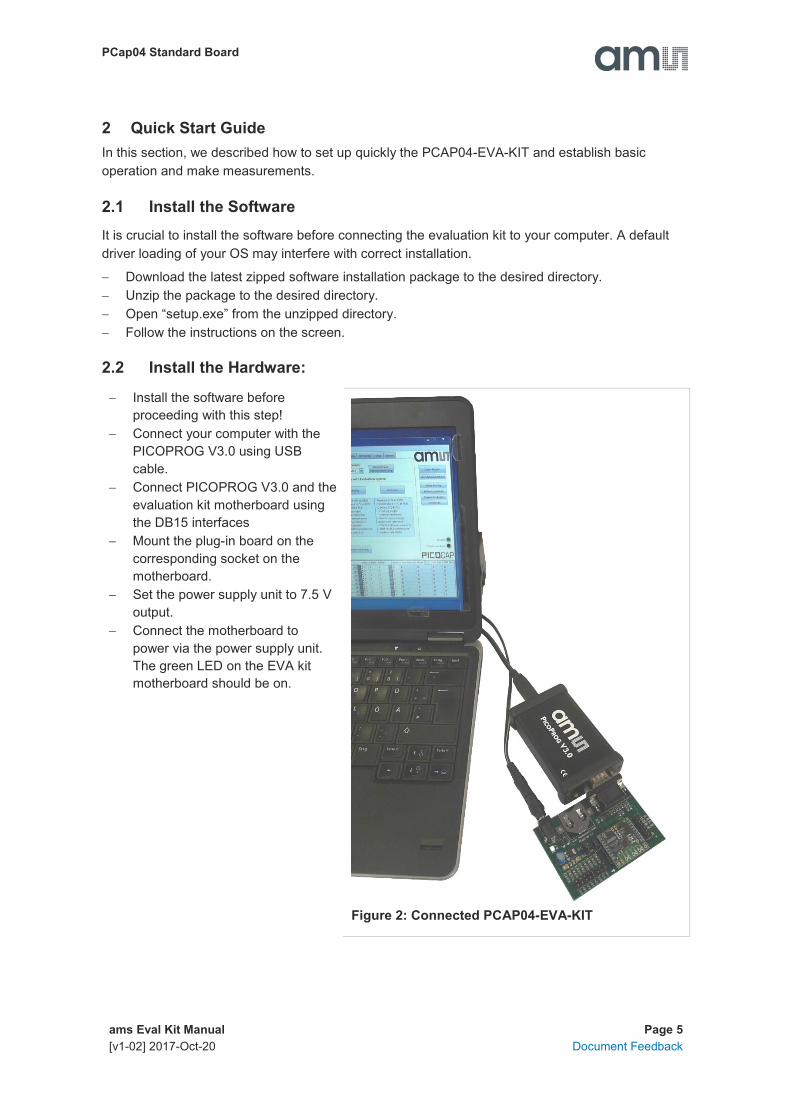
2.2 Install the Hardware:
Install the software before
proceeding with this step!
Connect your computer with the
PICOPROG V3.0 using USB
cable.
Connect PICOPROG V3.0 and the
evaluation kit motherboard using
the DB15 interfaces
Mount the plug-in board on the
corresponding socket on the
motherboard.
Set the power supply unit to 7.5 V
output.
Connect the motherboard to
power via the power supply unit.
The green LED on the EVA kit
motherboard should be on.
Figure 2: Connected PCAP04-EVA-KIT

PCap04 Standard Board
ams Eval Kit Manual Page 6
[v1-02] 2017-Oct-20 Document Feedback
2.3 Quick Start for Initial Measurements
From the “Start” menu, go to “All Programs” and then to the “acam” directory. Double click the
“PCap04 Frontpanel” icon to begin execution of the evaluation kit software. The following screen
should appear:
Figure 3: Setup page
Click the “Verify Interface” Button to confirm communication with PICOPROG V3.0 is working:
Figure 4: Verify Message
The PCap04 plug-in board is pre-assembled with ceramic capacitors to emulate capacitive sensors.
These capacitors, each 10 pF in value, are connected to the 6 ports PC0 to PC5.

PCap04 Standard Board
ams Eval Kit Manual Page 7
[v1-02] 2017-Oct-20 Document Feedback
To begin measurements using these preinstalled components, it is necessary to make the following
adjustments on the “CDC Frontend” tab:
1. “Capacitive Measurement Scheme” section should be set to “Floating | Single”.
2. All the capacitance ports should be turned on using the Cap. Port. Select buttons
3. The Stray Compensation setting should be set to “Both”.
The resulting settings under the CDC tab should look like this:
Figure 5: CDC Frontend page at the start

PCap04 Standard Board
ams Eval Kit Manual Page 8
[v1-02] 2017-Oct-20 Document Feedback
To begin measurements, on the right side of the window, click the following buttons in the order
listed:
1. “Power On Reset”
2. “Write Complete”
3. “Start Measurement”
Measurements should now be running and your screen should resemble the following:
Figure 6: CDC Frontend page in use
The C1 and C2 values should be continually updating but remain within a reasonably small
standard deviation as shown.
At this point if the above steps have been successfully completed basic operation of the EVA kit
should be achieved. The following sections provide a detailed description of the hardware and
software for advanced operation.

PCap04 Standard Board
ams Eval Kit Manual Page 9
[v1-02] 2017-Oct-20 Document Feedback
3 Hardware Description
3.1 Connecting Capacitors and Resistors
This evaluation kit can be used for evaluating capacitance measurement by connecting capacitive
sensors. Further, it can be used for evaluating temperature measurement by connecting external
temperature sensitive resistors or for generating quasi analog voltage (pulse width/density
modulated) that is dependent on the sensor connected to the system.
Depending on the purpose of evaluation, a modification has to be made to the same plug-in board.
Following is a picture of the Mother board with the plug-in board.
Figure 7: The evaluation kit’s motherboard and plug-in board
The following sections describe the modifications for each application in detail.
3.2 Hardware Architecture
3.2.1 PCAP04 BOARD
For the purpose of evaluating the capacitance measurement using PCapØ4, the plug-in board is
pre-assembled with ceramic capacitors to emulate capacitive sensors. These capacitors, each
10 pF in value, are connected to the 6 ports PC0 to PC5. They are connected as single sensors in
floating mode, i.e. each capacitor is connected between 2 ports, and hence there are 3 x 10 pF on-
board capacitors. Please refer to section 3 of the PCapØ4 data sheet for more information on how
to connect capacitors to the chip. In case using external reference, the capacitor connected
between ports PC0 and PC1 is taken as the reference capacitor.
PCap04 Standard Board
ams Eval Kit Manual Page 10
[v1-02] 2017-Oct-20 Document Feedback
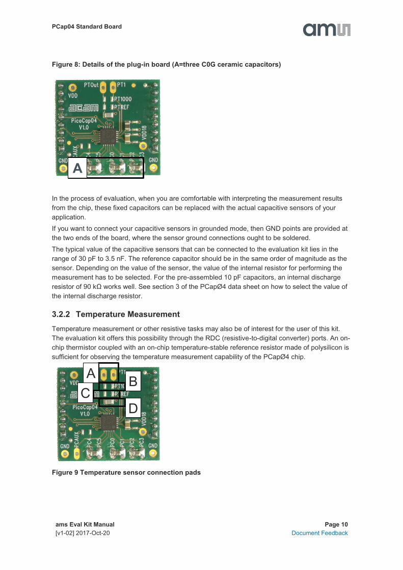
Figure 8: Details of the plug-in board (A=three C0G ceramic capacitors)
In the process of evaluation, when you are comfortable with interpreting the measurement results
from the chip, these fixed capacitors can be replaced with the actual capacitive sensors of your
application.
If you want to connect your capacitive sensors in grounded mode, then GND points are provided at
the two ends of the board, where the sensor ground connections ought to be soldered.
The typical value of the capacitive sensors that can be connected to the evaluation kit lies in the
range of 30 pF to 3.5 nF. The reference capacitor should be in the same order of magnitude as the
sensor. Depending on the value of the sensor, the value of the internal resistor for performing the
measurement has to be selected. For the pre-assembled 10 pF capacitors, an internal discharge
resistor of 90 kΩ works well. See section 3 of the PCapØ4 data sheet on how to select the value of
the internal discharge resistor.
3.2.2 Temperature Measurement
Temperature measurement or other resistive tasks may also be of interest for the user of this kit.
The evaluation kit offers this possibility through the RDC (resistive-to-digital converter) ports. An on-
chip thermistor coupled with an on-chip temperature-stable reference resistor made of polysilicon is
sufficient for observing the temperature measurement capability of the PCapØ4 chip.
Figure 9 Temperature sensor connection pads
A
C B
D
A

PCap04 Standard Board
ams Eval Kit Manual Page 11
[v1-02] 2017-Oct-20 Document Feedback
Pos. Item Comment
A Port PT1 for second external
temperature sensor
not supported by the standard firmware
B Port PT0 for external temperature
sensor
C Port PT2 for external reference
resistor
D 10 nF COG
However, there is a possibility to connect the reference resistor and the thermistor externally to the
chip, too. In case of external resistors, the temperature-stable reference resistor ought to be
connected at port PT2REF on the plug-in board. The board allows you to connect the external
thermistor, e.g. a PT1000 sensor at port PT0 (or PT1, not supported yet by the standard firmware).
In any case, for the temperature measurement, an external capacitor 10 nF C0G has to be
connected to the chip; it is already pre-assembled on board.

PCap04 Standard Board
ams Eval Kit Manual Page 12
[v1-02] 2017-Oct-20 Document Feedback
3.2.3 Pulse Code Generation
Any of the capacitance or temperature measurement results from the PCapØ4 chip can be given
out as a pulse width modulated or pulse density modulated signal. This output can be filtered to
generate an analog output signal that can be used for further controlling.
These pulse width or pulse density codes can be generated at Ports PG0, PG1, PG2 or PG3 (in
block A). Since ports PG0 and PG1 are used for the SPI Interface in the board, the hardware allows
to get a valid pulse width/density modulated signal on PG2 or PG3. However, when I2C
communication mode is used the pulsed signals can be optionally obtained on the ports PG0 and
PG1.
Figure 10 General purpose interface ports PG0 to PG3 in block A
3.2.4 Motherboard
The motherboard connects to the PICOPROG V3.0 programmer. It serves the various power
options. It can be powered via wall plug supply (B), the voltage being set from 1.8 V to 4.5 V by
jumpers (C). Further, it supports a battery power option (D). The power options are switchable via
jumper (E). Power present is indicated by a green LED.
There is a jumper ‘Current’ on the mother board (F). The current consumption of the PCapØ4 chip
during operation can be directly measured from these jumper terminals.
All interface signals and general purpose I/O signals can be monitored by means of a separate
jumper in block A.
E F
C
B
A
D

PCap04 Standard Board
ams Eval Kit Manual Page 13
[v1-02] 2017-Oct-20 Document Feedback
4 Software Description
4.1 Initialization
Configuration files, Firmware, Settings and calibration data are subsumed in a project (.prj) file.
When opening a project file then automatically the configuration and firmware data will be
transferred to the chip and the chip is initialized.
Step 1: The first to do after starting the evaluation software is to read the device version from Chip
by pressing the button or to select the supported PICOCAP device on the setup page. In the initial
phase start with our standard firmware that calculates the capacitance ratios and resistance ratios.
It automatically recognizes the operation mode and takes care of the set number of capacitors and
the kind of connection. But it does no further processing.
Step 2: If you want to change from the default SPI to I2C interface, please select under Interface -->
Bus --> I2C. The LED on the PICOPROG V3.0 programmer should now turn red. When the LED
does not glow at all, then it indicates that the interface is faulty.
Step 3: By pressing the ‘Standard’-button, the standard project file will be open.
You also may load your own project file.
Step 4: Open Graph window and press ‘Start Measurement’.
4.2 Graphical User Interface
Next, the main front panel comes up. Overall, the graphical user interface offers various windows
for on-line configuration, for parameter and calibration data setting, and of course for the graphical
and numerical display of the measurement data. The various windows will be explained in this
chapter.
4.2.1 Front Panel
This is the main window. On the right side, the front panel shows six general buttons:
Open Graph Open a window for graphic representation of measurement data
Start Measurement Start or stop a running measurement
Write Config. Transfer once more, the present settings in the evaluation software to the chip (in
case of doubt)
Write Complete Transfer the complete firmware, calibration data and configuration to the chip
Power On Reset After Power up reset, ‘Write Config.’ may be necessary.
Init Reset With an init reset, the chip is re-initialized with respect to its frontend and
processor.

PCap04 Standard Board
ams Eval Kit Manual Page 14
[v1-02] 2017-Oct-20 Document Feedback
4.2.1.1 Setup Page
Figure 11 Setup page
Options on ‘Setup’ page:
Select Device Select the PICOCAP device which you use.
<PCap04v0> means silicon version “Z”
<PCap04v1> means release silicon version “v1”
Read Device
Version from Chip
Reads the device version from chip
Standard Opens the <Selected Device>_standard.prj project file with configuration and
standard firmware.
Humidity Opens the <Selected Device>_humidity.prj project file with configuration and
linearization firmware.
Pressure Opens the <Selected Device>_pressure.prj project file with configuration and
linearization firmware.

PCap04 Standard Board
ams Eval Kit Manual Page 15
[v1-02] 2017-Oct-20 Document Feedback
Verify Interface When everything is in order, then pressing this button will indicate the release
version number of the software and of the PICOPROG V3.0 Firmware. It also
confirms with ‘Memory read/write: OK’ if a supported PICOCAP device is present.
The lower part of the window is used for real-time numerical display of the measurement results. In
principal it shows the content of the read registers. The content itself depends on the firmware.
Figure 1-16 shows the content as it is given with the standard firmware. The first six rows show the
capacitance ratios, the last two rows show the temperature result (resistance ratio or linearized
temperature).
The tab has 12 columns of information, defining labels, data format, resolution specification (white
background) and results (grey background). The information in the white fields increase
convenience of reading and is stored in the project files (*.prj). All number may get a character to
indicate the well-known prefixes for denoting the factor in thousands (‘p’, ‘f’, ‘a’, ‘k’... ).
Name Label for the register content, depends on the firmware.
Results Raw hex data display of the result register content. The column before shows the width.
The button column after shows whether the result is signed or unsigned.
Filter Selection of various software filters like Sinc (rolling average) and Median (non-linear
filter).
fpp This column shows the size of the fractional part of the fixed point number and the
necessary shift. Depends on the firmware.
Factor The factor is a scaling factor that allows to scale the result according to the reference
capacitor. Factor = ‘1’ gives back the initial capacitance ratio in column ‘Final Result’.
Offset Offset to be added or subtracted in the evaluation software.
Auto Offset By pressing [AO], the software re-calculates the ‘Offset’, setting back the ‘Final Result’ to
0
Span Number that defines the maximum span of the sensor. Is relevant only for the calculation
of the resolution in column SNR [bit].
Final Result Display of the final result, scaled by ‘Factor’ and the ‘Offset’ added.
Mean Display of the mean value. The sample size can be selected.
Std.Dev Standard deviation of the ‘Final Result’.
SNR [bit] Signal-to-Noise ratio in bit, calculated as ‘Span’/ ‘Std.Dev.’

PCap04 Standard Board
ams Eval Kit Manual Page 16
[v1-02] 2017-Oct-20 Document Feedback
4.2.1.2 CDC Frontend Page
Figure 12 CDC Frontend page

PCap04 Standard Board
ams Eval Kit Manual Page 17
[v1-02] 2017-Oct-20 Document Feedback
Options on ‘CDC Frontend page:
Capacitance
Measurement Scheme
Grounded | Single – Single capacitive sensor connected between a port and
ground.
Grounded | Differential – Differential capacitive sensor connected between 2
ports with the middle tap of the sensor connected to ground.
Floating | Single – Single capacitive sensor connected between 2 ports.
Floating | Differential – Differential capacitive sensor connected between 2
ports with the middle tap of the sensor connected to another 2 ports.
Cap. Port Select Select which capacitive ports have to be measured (Ports 0-5), i.e. at which
ports the sensors have been connected in hardware.
Stray Compensation None – No compensation
Internal – One additional measurement performed through only the chip-
internal stray capacitance with respect to ground.
External – One additional measurement per port pair, performed through a
parallel connection of the capacitance at the two ports with respect to ground.
Both – Both internal and external compensation together.
Discharge Resistance
Port 0..3
Selects the value of the internal resistance (180k, 90k, 30k, 10k) for
measurements on port PC0 to PC3 through which the discharge cycles during
measurement are to be performed. This value has to be selected in
accordance with the capacitance value of the sensor.
Discharge Resistance
Port 4..5
Selects the value of the internal resistance (180k, 90k, 30k, 10k) for
measurements on port PC4 to PC5 through which the discharge cycles during
measurement are to be performed. This value has to be selected in
accordance with the capacitance value of the sensor.
Charge Resistance Choice of one out of 4 on-chip charging resistors (180k, 10k) for the CDC.
Permitting to limit the charging current and avoiding transients.
C Reference Select Switching between external and internal reference capacitance.
Internal Cap Selection of internal reference capacitance value. (0..31pF)

PCap04 Standard Board
ams Eval Kit Manual Page 18
[v1-02] 2017-Oct-20 Document Feedback
4.2.1.3 CDC Page
Figure 13 CDC page
Options on ‘CDC page:
Cycle Control
Precharge Time Time to charge via resistor for current limitation, can be set in multiples of the
cycle clock
Fullcharge Time Time for final charge without current limitation, can be set in multiples of the
cycle clock
Discharge Time Time to discharge the capacitor, can be set in multiples of the cycle clock
C_FAKE Number of fake measurements per measurement cycle. Performing fake
measurements may help in reducing noise.

PCap04 Standard Board
ams Eval Kit Manual Page 19
[v1-02] 2017-Oct-20 Document Feedback
C_AVRG Enables averaging the measurement results over multiple measurement cycles.
Setting to 1 No averaging, Setting to any number N, will result in averaging
over N measurement cycles for generating one measurement result. (0..8191)
Cycle Clock Select 50,0kHz | Low Power – Single capacitive sensor connected between a port and
ground.
500kHz | High Speed/4 – Differential capacitive sensor connected between 2
ports with the middle tap of the sensor connected to ground.
2,00MHz | High Speed – Single capacitive sensor connected between 2 ports.
Conversion Duration Displays the entire conversion duration per cycles for averaging and fake
measurements.
C_TRIG_SEL Selects the source that triggers the start of a capacitance measurement
Continuous – Continuous measurement, self-triggering. Recommended when
no temperature measurement is made in parallel.
Read Triggered – Triggered by read out
Timer Triggered – Depending on the setting the ‘Conversion Time’. Generally
recommended setting less prone to error conditions.
Timer Triggered (Stretched) – Depending on the setting the CONV_TIME. The
parameter is used as sequence period.
Pin triggered – Triggered by external Pin, selectable from option ext.Trigger-Pin
Opcode Triggered | Off – Started by SPI Command 0x8C
Continuous (exp.) – (not recommended)
Ext. Trigger-Pin Used to select the pin to be used as the source of trigger for the capacitance
measurement.
NOTE: In the delivered EVA board, the pins DSP_IN0 and DSP_IN1 are part of
the SPI communication interface, hence only DSP_IN2 and DSP_IN3 selections
are relevant.
Conversion Control
CONV_TIME Sets the conversion time in multiples of twice the period of the low-frequency
clock
Conversion Time Displays the entire conversion time per measurement.
Measuring rate Displays the frequency at which capacitive measurement data is transferred
from the DSP to the interface (SPI or I2C).

PCap04 Standard Board
ams Eval Kit Manual Page 20
[v1-02] 2017-Oct-20 Document Feedback
4.2.1.4 RDC Page
Figure 14 RDC page
Options on ‘RDC’ page:
Temp.Sensor0 To select a thermistor connected to port PT0/REF for temperature
measurement. This could be e.g. an external PT1000.
Temp.Sensor1 To select a thermistor connected to port PT1 for temperature measurement.
Temp.Sensor2 To select either the internal aluminum (ALU) thermistor for temperature
measurement.
Reference To select either the internal Poly-Si thermistor or an external reference resistor
at port PT0/REF for temperature measurement.

PCap04 Standard Board
ams Eval Kit Manual Page 21
[v1-02] 2017-Oct-20 Document Feedback
Cycle Control
Precharge Time Displays the precharge time. It depends on R_OLF_DIV.
Fullcharge Time Displays the fullcharge time It depends on R_OLF_DIV.
Discharge Time Set the discharge time. It depends on R_OLF_DIV.
R_AVRG Set averaging for temperature measurement.
R_FAKE Set number of fake measurements per temperature measurement cycle.
Conversion Duration Displays the entire conversion duration per cycles for averaging and fake
measurements.
Conversion Control
Temp. Trigger Select Selects the source that triggers the start of a temperature measurement
Off: Default setting when no temperature measurement is wanted. In this case,
a temperature measurement can still be started by SPI Command 0x8E.
OLF_CLK: Triggered by Low-frequency oscillator.
Pin-Triggered: Triggered by external Pin, selectable from option ext.Trigger-Pin
CDC asynchronous: Depending on the setting in the ‘T_TRIG_PREDIV’
counter on the RDC page. The DSP is triggered by the RDC end of conversion.
If RDC rate is less than CDC rate the DSP is triggered directly from the CDC for
inactive RDC conversions.
CDC synchronous: Depending on the setting in the ‘T_TRIG_PREDIV’ counter
on the RDC page. The DSP is triggered by the RDC end of conversion.
Assuming that RDC rate is less than the CDC rate, the inactive RDC
conversions are replaced by a delay.
R_TRIG_PREDIV For CDC and OLF options the RDC measure rate can be reduced by setting a
divider.
Conversion Time Displays the entire conversion time per measurement.
Measuring Rate Displays the frequency at which capacitive measurement data is transferred
from the DSP to the interface (SPI or I2C).
Ext. Trigger-Pin Used to select the pin to be used as the source of trigger for the capacitance
measurement.
NOTE: In the evaluation board, the pins DSP_IN0 and DSP_IN1 are part of the
SPI communication interface, hence only DSP_IN2 and DSP_IN3 selections can
be used.

PCap04 Standard Board
ams Eval Kit Manual Page 22
[v1-02] 2017-Oct-20 Document Feedback
4.2.1.5 PDM / PWM Page
Figure 15 PDM/PWM page
Options on ‘PDM / PWM’ Page:
Clock Select Selects the clock frequency to be used for the PWM/PDM generation.
Resolution Resolution of the output in bits. This resolution also determines the pulsed
output range.
Pulse Interface Select Select the pulse interface – Pulse Width Modulated Output (PWM) or Pulse
Density Modulated (PDM) Output. Of the two, the PDM is the recommended
interface.
With PWM option, 100 kHz clock and 10-bit resolution the resulting PWM output
frequency = (100 kHz / 1024) ~ 100 Hz.
PCap04 Standard Board
ams Eval Kit Manual Page 23
[v1-02] 2017-Oct-20 Document Feedback
Toggle Enable activates toggle flip flop at Pulse Interface Output, especially for PDM to
create 1:1 duty factor
Pulse Select Select the measurement result which has to be given out as pulsed output – any
of the capacitance or temperature measurement results.
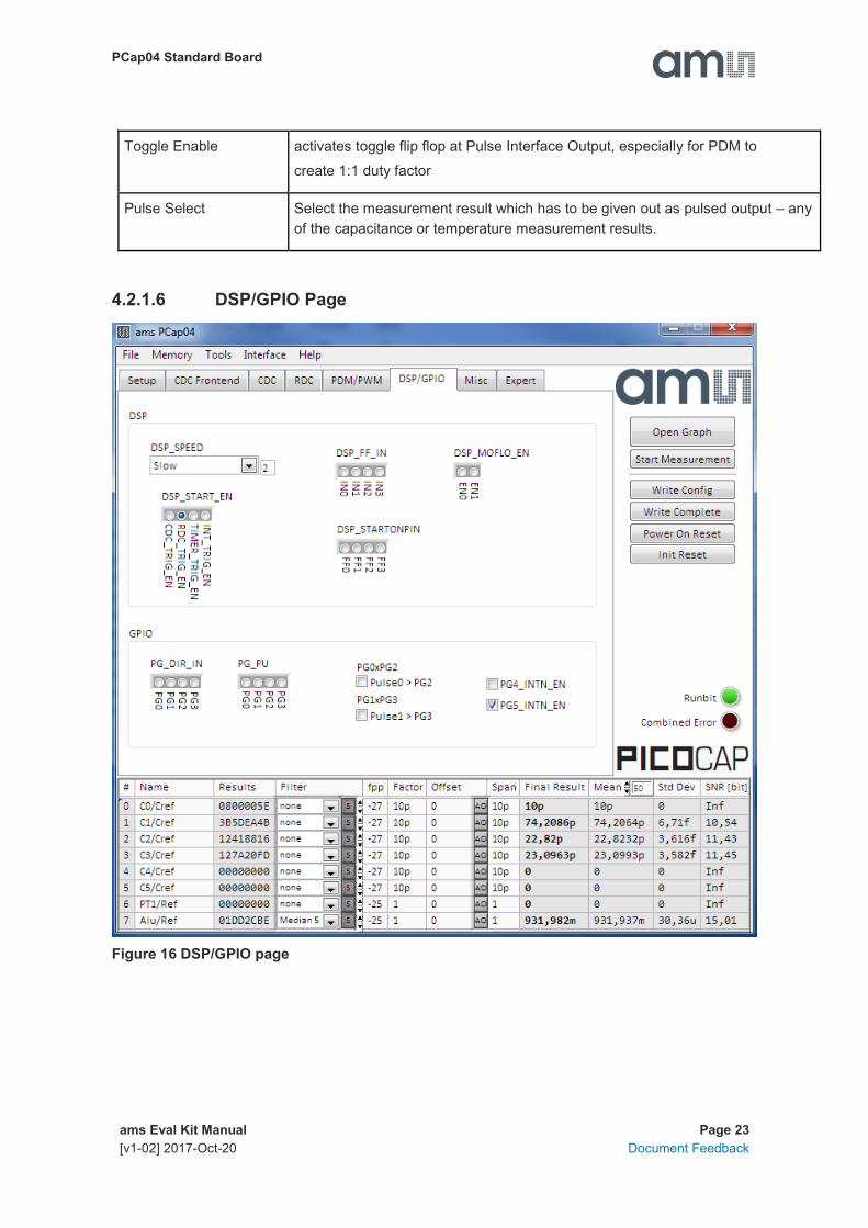
4.2.1.6 DSP/GPIO Page
Figure 16 DSP/GPIO page

PCap04 Standard Board
ams Eval Kit Manual Page 24
[v1-02] 2017-Oct-20 Document Feedback
Options on ‘DSP/GPIO’ Page:
DSP
DSP_SPEED Select the DSP Speed.
Choose between Fastest, Fast, Slow and Slowest.
DSP_FF_IN Pin mask for latching flip-flop activation (PG0 to PG3)
DSP_MOFLO_EN Activates anti-bouncing filter in PG0 and PG1 lines
DSP_STARTONPIN Not supported by standard firmware
The DSP can be started externally by a signal on a pin; these buttons select the
pin that has to be sensed for detecting the start signal.
DSP_START_EN Mask for activating various trigger sources for starting the DSP
GPIO
PG_DIR_IN To configure the ports PG0-PG3 as input (otherwise output)
PG_UP To enable the internal pull up on the ports PG0-PG3
PG0_X_PG2 Possible only when the selected interface for communication is IIC. Interchange
PortG0 with PortG2. This is useful when the Pulsed output is needed on Port PG0
instead of PG2.
PG1_X_PG3 Possible only when the selected interface for communication is IIC. Interchange
PortG1 with PortG3. This is useful when the Pulsed output is needed on Port PG1
instead of PG3.
PG4_INTN_EN Map the Interrupt output from chip, INTN to Port PG4.
This setting is useful for 24 pin QFN package, because the dedicated INTN pin is
absent in this version.
PG5_INTN_EN Map the Interrupt output from chip, INTN to Port PG5.
This setting is useful for 24 pin QFN package, because the dedicated INTN pin is
absent in this version.

PCap04 Standard Board
ams Eval Kit Manual Page 25
[v1-02] 2017-Oct-20 Document Feedback
4.2.1.7 Misc. Page
Figure 17 Misc. page
Options on ‘Misc.’ Page:
LF Clock
OLF_CTUNE Coarse-tune the low frequency clock. (10kHz, 50kHz, 100kHz, 200kHz)
OLF_FTUNE Fine-tune the low frequency clock. (0..15)
HF Clock
OX_RUN Controls the permanency or the latency of the OX generator. Latency means an
oscillator settling time before a measurement starts.

PCap04 Standard Board
ams Eval Kit Manual Page 26
[v1-02] 2017-Oct-20 Document Feedback
OX_DIS Disable the OX clock.
OX_AUTOSTOP_DIS Disables the automatic stop function of the OX generator between the individual
measure sequences.
OX_STOP Stop the OX-generator
OX_DIV4 OX clock frequency := raw freq./4
Guarding
Guarding Port Select Individual Guard enable to each Port PC0..PC5
C_G_OP_RUN permanent – Guarding OP is permanent activated
(additional power consumption)
pulsed – Guarding OP set to sleep mode between CDC conversions
C_G_TIME Controls the pre-charge phase
C_G_OP_EXT Switch between internal guarding OP and an optional external OP
C_G_OP_TR Trim power consumption of guarding OP.
C_G_OP_ATTN Capacitive attenuation of Guarding OP.
C_G_OP_VU OP Gain (from Sense Port to Guard).
4.2.1.8 Expert Page
Please modify the settings on the Expert page only in consultation with acam Support team.
4.2.2 Front Panel Menus
4.2.2.1 File Menu
Figure 18 File Menu
PCap04 Standard Board
ams Eval Kit Manual Page 27
[v1-02] 2017-Oct-20 Document Feedback
Open Project Open project file *.prj that subsumed
the firmware and configuration
filenames and the settings and
Calibration data
Save Project Here you can save your own project
file.
Import Import configuration (*.cfg),
calibration data (*.dat) or firmware.
Note: Any import will modify the
active project file! Save the project
file under a new name.
Export Here you can export Config (*.cfg),
Calibration (*.dat), Memory (*.dat) or
Firmware (*.hex), separately
Close Close the evaluation software
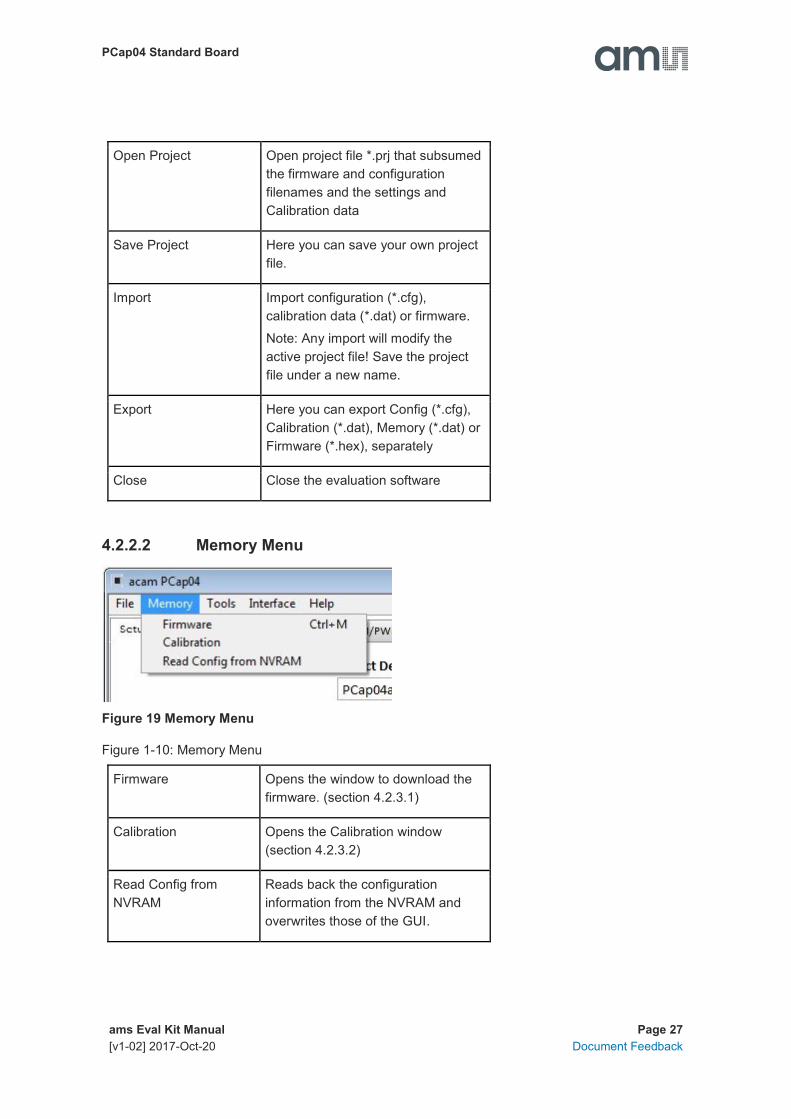
4.2.2.2 Memory Menu
Figure 19 Memory Menu
Figure 1-10: Memory Menu
Firmware Opens the window to download the
firmware. (section 4.2.3.1)
Calibration Opens the Calibration window
(section 4.2.3.2)
Read Config from
NVRAM
Reads back the configuration
information from the NVRAM and
overwrites those of the GUI.

PCap04 Standard Board
ams Eval Kit Manual Page 28
[v1-02] 2017-Oct-20 Document Feedback
4.2.2.3 Tools Menu
Figure 20 Tools Menu
Run Measurement Start the measurement
Graph Opens the window for graphical display
of the various measurement results
(section 4.2.3.4)
Registers Opens the Register window (section
4.2.3.5)
Linearize Opens the Linearize window
Assembler Opens the assembler
4.2.2.4 Interface Menu
Figure 21 Interface Menu
Bus Select between SPI and I2C interface
USB Opens the USB Communications
window with PicoProg V3.0 Settings
and the possibility to send opcodes

PCap04 Standard Board
ams Eval Kit Manual Page 29
[v1-02] 2017-Oct-20 Document Feedback
4.2.2.5 Help Menu
Figure 22 Help Menu
Help Contents Opens the help window
Check Errors Opens the error message window if
there is an inconsistency after
plausibility check.
About Version
After each change in settings, the evaluation software automatically performs a plausibility check in
the background. If a setting is not allowed or doesn’t fit with the setting of the other parameters, the
faulty setting is highlighted in red color.

PCap04 Standard Board
ams Eval Kit Manual Page 30
[v1-02] 2017-Oct-20 Document Feedback
4.2.3 Special Windows
4.2.3.1 Firmware Window
In the ‘Firmware’ Window the write data can be edited.
If the NVRAM is read (‘Read’ button), the content is automatically compared with the ‘Write Data’
window content. If contents are equal this will be indicated by a green illuminated LED.
Figure 23 Firmware Window

PCap04 Standard Board
ams Eval Kit Manual Page 31
[v1-02] 2017-Oct-20 Document Feedback
Open File Select and open a firmware file (.hex) or import firmware from a project file. The
content is shown in the ‘Write Data’ window.
Reload File Reload the last opened firmware file (.hex). The content is shown in the ‘Write
Date’ window again.
Read Pressing this button, the content of the NVRAM is read and shown in the ‘Read
Data’ window. In ‘Address’ and ‘Length’ you can specify how many bytes you want
read, starting at which address.
Write Writes the firmware into the chip’s NVRAM. The status of the write process is
indicated by the green bar. The successful end is indicated by a pop-up window.
For verification we recommend to read back the NVRAM afterwards and compare
it with the source.
Firmware Version In the firmware, a specific address is reserved to save 3 byte information about the
application and the version of the software. The coding is specified in the header
file of the supported PICOCAP device, for example: pcap_standard.h. The header
file is found in the library directory of the assembler.
PCap04 Standard Board
ams Eval Kit Manual Page 32
[v1-02] 2017-Oct-20 Document Feedback
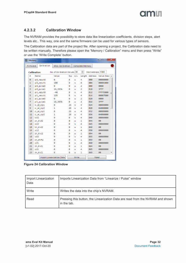
4.2.3.2 Calibration Window
The NVRAM provides the possibility to store data like linearization coefficients, division steps, alert
levels etc.. This way, one and the same firmware can be used for various types of sensors.
The Calibration data are part of the project file. After opening a project, the Calibration data need to
be written manually. Therefore please open the “Memory / Calibration” menu and then press “Write”
or use the ‘Write Complete’ button.
Figure 24 Calibration Window
Import Linearization
Data
Imports Linearization Data from “Linearize / Pulse” window
Write Writes the data into the chip’s NVRAM.
Read Pressing this button, the Linearization Data are read from the NVRAM and shown
in the tab.

PCap04 Standard Board
ams Eval Kit Manual Page 33
[v1-02] 2017-Oct-20 Document Feedback
4.2.3.3 Misc. Calibration Window
This window shows miscellaneous calibration bits at address d’956-d’959 (4 byte). The meaning of
the content strongly depends on the firmware.
Figure 25 Misc. Calibration Window
Write Writes the data into the chip’s NVRAM.
Read Pressing this button, the bits are read from the NVRAM and shown in the tab.

PCap04 Standard Board
ams Eval Kit Manual Page 34
[v1-02] 2017-Oct-20 Document Feedback
Figure 26 Complete Memory Window
Write Writes the complete NVRAM.
Store The complete data transfer from Memory (volatile) to FLASH (non-volatile) is
performed by a STORE
Erase During this ERASE procedure, first the complete NVRAM will erased (set to zero)
and afterwards the MEM_LOCK bits will be cleared.
Read Pressing this button, the complete NVRAM are read and shown in the tab.
Recall This means that the complete Memory is copied from the FLASH (non-volatile) to
the Memory (volatile). After a power-on reset, a recall is processed.

PCap04 Standard Board
ams Eval Kit Manual Page 35
[v1-02] 2017-Oct-20 Document Feedback
4.2.3.4 Graph Window
Figure 27 Graph Window
The data to be displayed are selected in the field at the bottom right. The labels in the buttons are
the same as in the diagnostics window. To display data press the corresponding button so that it
gets green. Top right of the ‘Graph’ Windows are various options for automatic zoom in/out, center
or scale in other ways. Below the graph are various automatic zoom functions for the x-axis and the
y-axis.
Y-Zoom will be chanced with the keys [+], [-] and X-Zoom with the keys [*], [/]. With the cursor
control keys [←], [→], [↑], [↓] is it possible to move the graph.
The data displayed can be stored into a text file. For long-term investigations it is possible to reduce
the data displayed and stored. The field ‘Data Reduction’ allows to define the level of data
reduction.
4.2.3.5 Registers Window
These windows display the configuration data in hexadecimal format as they are currently used.
Also the result registers‘ content is shown in hexadecimal format, but updated only when the button
is pressed. Finally, the various status bits are shown.

PCap04 Standard Board
ams Eval Kit Manual Page 36
[v1-02] 2017-Oct-20 Document Feedback
Figure 28 Write Registers and Results

PCap04 Standard Board
ams Eval Kit Manual Page 37
[v1-02] 2017-Oct-20 Document Feedback
4.2.4 Linearize
4.2.4.1 Sensor Characterization
The first step is the characterization of the sensor. Therefore, it is necessary to collect data at
several measurement points and at several temperatures.
As mentioned earlier, the data collection should be made of minimum 12 measurements, taken at
least at 3 different temperatures. The temperatures should cover the operating temperature range
of interest of the final device. The number of calibration points is set at the top left. This is the first
thing to be done. Then calibration can begin. Line by line the user can enter the reference values for
acquire button to get the actual ci_ratio result. But of course the value can be entered manually, too.
The graph on the bottom left shows the Z, ϑ distribution of the calibration points. Ideally it should
have dots on three different lines covering the operating range of the sensor.
The table on the left shows the calculated calibration coefficients and the graph below shows the
deviation due to the mathematical approximation.
Figure 29 Sensor Characterization

PCap04 Standard Board
ams Eval Kit Manual Page 38
[v1-02] 2017-Oct-20 Document Feedback
4.2.4.2 Temperature Sensor Characterization
Together with the calibration of the capacitance sensor it is mandatory to calibrate the temperature,
too. Whether the internal aluminum sensor is used or an external platinum sensor or any other
sensor: they need to be calibrated to get the correct temperature information which is then used as
input for the polynomial correction of the capacitance measurement.
The tab „Temperature Sensor Characterization” (Figure 1-18) offers a tool very similar to the
capacitive sensor characterization. The resistance ratio has to be collected at several temperature
points. For best approximation 4 calibration points are needed. In case of 2 or 3 calibration points a
2nd respectively a 3rd order polynomial is calculated.
Figure 30 Temp. Sensor Characterization
On the right side of the tab “Temperature Sensor Characterization” there are two buttons to select
default characteristic data for the internal aluminum sensor and a platinum sensor. The aluminum is
assumed to be linear in a range of 10 °C to 70°C so only two coefficients are used.
In case the default values are used it is necessary to have at least a two point calibration of the
temperature (see next section).

PCap04 Standard Board
ams Eval Kit Manual Page 39
[v1-02] 2017-Oct-20 Document Feedback
4.2.4.3 One/Two Point Calibration
Once a batch is characterized with respect to the capacitive sensor and the resistive temperature
sensor it might be sufficient to perform two-point or even one-point calibration for the rest of the
sensors in the batch.
The tab “One/Two Point Calibration” offers a simple GUI to do that. On this page the user enters the
reference values for Z and ϑ. CCP1 stands for capacitance calibration point 1 etc.. When the
calibration conditions are reached pressing the acquire buttons will read the actual ratios while the
theoretical ones are calculated on basis of the linearization coefficients. Together with
programmable limits for minimum and maximum this gives an additional set of 12 parameters to be
written into the EEPROM.
Figure 31 One/Two Point Calibration
PCap04 Standard Board
ams Eval Kit Manual Page 40
[v1-02] 2017-Oct-20 Document Feedback
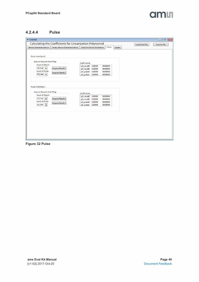
4.2.4.4 Pulse
Figure 32 Pulse

PCap04 Standard Board
ams Eval Kit Manual Page 41
[v1-02] 2017-Oct-20 Document Feedback
4.2.4.5 Expert
As indicated by the name this tab is for experts only. There you set the fixed point position of the
result Z. It further displays the numbers of division steps respectively shift operation to achieve the
maximum resolution over all calculations.
Those are stored in the NVRAM, too. But they are calculated by the DLL and for information
purpose only.
Figure 33 Expert

PCap04 Standard Board
ams Eval Kit Manual Page 42
[v1-02] 2017-Oct-20 Document Feedback
4.2.5 Assembler
Figure 34 Assembler
This is a comfortable editor with syntax highlighting, search and replace, copy and paste functions.
Under menu item “Assembler” the user finds the compile and download options.
Whether the call of these functions was successful or not is indicated by the messages at the
bottom of the assembler window.
Debugging is not supported in this software revision.
4.3 Scaling Results
PCap04 in general calculates capacitance ratios. The measured ratios include of course all effects
from parasitic capacitances. Nonetheless, in many cases users might be interested in an intuitive
understanding the displayed values without making a full calibration run.
The following shows by example how to set Factor and Offset to give a suitable display.
PCap04 Standard Board
ams Eval Kit Manual Page 43
[v1-02] 2017-Oct-20 Document Feedback
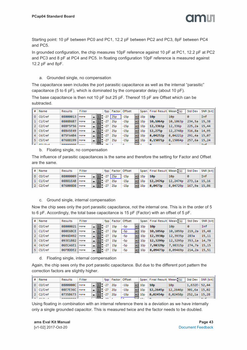
Starting point: 10 pF between PC0 and PC1, 12.2 pF between PC2 and PC3, 8pF between PC4
and PC5.
In grounded configuration, the chip measures 10pF reference against 10 pF at PC1, 12.2 pF at PC2
and PC3 and 8 pF at PC4 and PC5. In floating configuration 10pF reference is measured against
12.2 pF and 8pF.
a. Grounded single, no compensation
The capacitance seen includes the port parasitic capacitance as well as the internal “parasitic”
capacitance (5 to 6 pF), which is dominated by the comparator delay (about 10 pF).
The base capacitance is then not 10 pF but 25 pF. Thereof 15 pF are Offset which can be
subtracted.
b. Floating single, no compensation
The influence of parasitic capacitances is the same and therefore the setting for Factor and Offset
are the same.
c. Ground single, internal compensation
Now the chip sees only the port parasitic capacitance, not the internal one. This is in the order of 5
to 6 pF. Accordingly, the total base capacitance is 15 pF (Factor) with an offset of 5 pF.
d. Floating single, internal compensation
Again, the chip sees only the port parasitic capacitance. But due to the different port pattern the
correction factors are slightly higher.
Using floating in combination with an internal reference there is a deviation as we have internally
only a single grounded capacitor. This is measured twice and the factor needs to be doubled.

PCap04 Standard Board
ams Eval Kit Manual Page 44
[v1-02] 2017-Oct-20 Document Feedback
e. Floating, both compensation
Now all parasitic capacitances are compensated. The initial base capacitance without offset can
be used.
4.4 Scaling PDM Output
Here we describe how to scale the PDM output when working with the standard firmware. Open the
Memory window and select tab calibration:
Set fpp to 27 and s/u to S for signed. Enter the capacitance ratios at minimum and maximum sensor
signal. Set pix_pulse1 (max) to the value according to the set resolution of the PDM. This is 1023 at
10 bit and 65535 at 16 bit.
Press “write” to write the data into the chip.
PCap04 Standard Board
ams Eval Kit Manual Page 45
[v1-02] 2017-Oct-20 Document Feedback
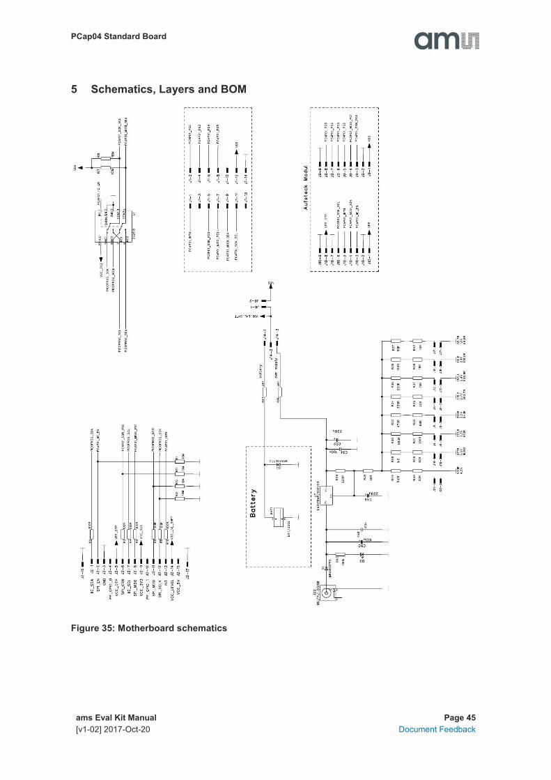
5 Schematics, Layers and BOM
Figure 35: Motherboard schematics

PCap04 Standard Board
ams Eval Kit Manual Page 46
[v1-02] 2017-Oct-20 Document Feedback
Figure 36: PCa04 AD board schematics

PCap04 Standard Board
ams Eval Kit Manual Page 47
[v1-02] 2017-Oct-20 Document Feedback
Figure 37: PCa04 AD board layout

PCap04 Standard Board
ams Eval Kit Manual Page 48
[v1-02] 2017-Oct-20 Document Feedback
Bill of Materials for PCap04 plug-in board
Item Qty Reference Part Name Description
2 1 C2 C805, 10u
3 1 C4 C805, 4u7
5 1 U1 PCAP04/QFN24
6 3 R1 R2 R3 R805, nc
4 2 C3 C5 C805, nc
1 1 C1 C805, nc CHIP-CAPACITOR

PCap04 Standard Board
ams Eval Kit Manual Page 49
[v1-02] 2017-Oct-20 Document Feedback
6 Ordering & Contact Information
Ordering Code Description
PCAP04-EVA-KIT PCap04 Eval Kit Standard Board
PCAP04-EVA-BOARD
Buy our products or get free samples online at:
www.ams.com/ICdirect
Technical Support is available at:
www.ams.com/Technical-Support
Provide feedback about this document at:
www.ams.com/Document-Feedback
For further information and requests, e-mail us at:
For sales offices, distributors and representatives, please visit:
www.ams.com/contact
Headquarters
ams AG
Tobelbader Strasse 30
8141 Premstaetten
Austria, Europe
Tel: +43 (0) 3136 500 0
Website: www.ams.com

PCap04 Standard Board
ams Eval Kit Manual Page 50
[v1-02] 2017-Oct-20 Document Feedback
7 Copyrights & Disclaimer
Copyright ams AG, Tobelbader Strasse 30, 8141 Premstaetten, Austria-Europe. Trademarks
Registered. All rights reserved. The material herein may not be reproduced, adapted, merged,
translated, stored, or used without the prior written consent of the copyright owner.
Demo Kits, Evaluation Kits and Reference Designs are provided to recipient on an “as is” basis for
demonstration and evaluation purposes only and are not considered to be finished end-products
intended and fit for general consumer use, commercial applications and applications with special
requirements such as but not limited to medical equipment or automotive applications. Demo Kits,
Evaluation Kits and Reference Designs have not been tested for compliance with electromagnetic
compatibility (EMC) standards and directives, unless otherwise specified. Demo Kits, Evaluation Kits
and Reference Designs shall be used by qualified personnel only.
ams AG reserves the right to change functionality and price of Demo Kits, Evaluation Kits and
Reference Designs at any time and without notice.
Any express or implied warranties, including, but not limited to the implied warranties of
merchantability and fitness for a particular purpose are disclaimed. Any claims and demands and any
direct, indirect, incidental, special, exemplary or consequential damages arising from the inadequacy
of the provided Demo Kits, Evaluation Kits and Reference Designs or incurred losses of any kind (e.g.
loss of use, data or profits or business interruption however caused) as a consequence of their use
are excluded.
ams AG shall not be liable to recipient or any third party for any damages, including but not limited to
personal injury, property damage, loss of profits, loss of use, interruption of business or indirect,
special, incidental or consequential damages, of any kind, in connection with or arising out of the
furnishing, performance or use of the technical data herein. No obligation or liability to recipient or
any third party shall arise or flow out of ams AG rendering of technical or other services.

PCap04 Standard Board
ams Eval Kit Manual Page 51
[v1-02] 2017-Oct-20 Document Feedback
8 Revision Information
Changes from previous version to current revision 1-02 (2017-Oct-20) Page
Adding section “4.3 Scaling Results” 42
Adding section “4.4 Scaling PDM Output” 43
Updated screenshots and photos
Note: Page numbers for the previous version may differ from page numbers in the current revision.
Correction of typographical errors is not explicitly mentioned.


