Specific Electrical Conductance, Version 1.2 (8/2005) U.S. Geological Survey TWRI Book 9
2—SC
Tables
6.3–1. Equipment and supplies used for measuring conductivity................................................. 4
6.3–2. Example of cell constants for contacting-type sensors with electrodes and corresponding conductivity ranges .............................. 5
6.3–3. Correction factors for converting non-temperature-compensated values to conductivity at 25 degrees Celsius, based on 1,000 microsiemens potassium chloride solution .......................................... 10
6.3–4. Troubleshooting guide for conductivity measurement............................................ 20
Chapter A6. Field Measurements Specific Electrical Conductance, Version 1.2 (8/2005)
SC—3
SPECIFIC ELECTRICAL 6.3 CONDUCTANCE
EQUIPMENT AND SUPPLIES 6.3.1
The instrument system used to measure conductivity must be tested before each field trip and cleaned soon after use. Many conductivity instruments are available, including multiparameter instruments that include conductivity sensors. This section provides detailed informa-tion on the use of conductivity-specific instruments only, although instructions regarding conductivity standards and measurement meth-ods are applicable in general. Users must be familiar with the instruc-tions provided by the manufacturer. Every conductivity (or multiparameter) instrument must have a log book in which repairs and calibrations are recorded, along with manufacturer make and model description and serial or property number.
SPECIFIC ELECTRICAL CONDUCTANCE (CONDUCTIVITY)—
a measure of the electrical conductance of a substance
normalized to unit length and unit cross section at a
specified temperature.
By D.B. Radtke, J.V. Davis, and F.D. Wilde
Electrical conductance is a measure of the capacity of water (or other media) to conduct an electrical current. Electrical conductance of water is a function of the types and quantities of dissolved substances in water, but there is no universal linear relation between total dis-solved substances and conductivity.
The USGS reports conductivity in microsiemens per centimeter at 25 degrees Celsius (μS/cm at 25°C). The method described in this section for measuring conductivity is applicable to surface water and ground water, from fresh to saline.
Specific Electrical Conductance, Version 1.2 (8/2005) U.S. Geological Survey TWRI Book 9
4—SC
.
Table 6.3–1. Equipment and supplies used for measuring conductivity1
[°C, degrees Celsius; ≤ , less than or equal to; >, greater than; μS/cm, microsie-mens per centimeter at 25 degrees Celsius; L, liter]
Conductivity instrument and conductivity sensorBattery powered Wheatstone bridgeDirect readoutTemperature range at least –5 to +45°CTemperature compensating (25°C)Accuracy: Conductivity ≤100 μS/cm, within 5 percent of full scale
Conductivity >100 μS/cm, within 3 percent of full scaleThermistor thermometer sensor (for automatic temperature-
compensating models)Thermometer, liquid-in-glass or thermistorExtra sensors (if possible) and batteries, or backup instrumentConductivity standards at conductivities that approximate and bracket
field valuesCompositing and splitting device for surface-water samplesFlowthrough chamber or downhole instrument for ground-water mea-
surementsPlastic beakers (assorted sizes)Soap solution, nonphosphate (1 L)Hydrochloric acid solution, 5 percent volume-to-volume (1 L)Deionized water, 1 L, maximum conductivity of 1 μS/cmPaper tissues, disposable, soft, and lint freeBrush (small, soft)Waste disposal containerMinnow bucket with tether (or equivalent) for equilibrating buffer
solutions to sample temperatureInstrument log book for recording calibrations, maintenance, and
repairs
1Modify this list to meet the specific needs of the field effort.
As soon as possible after delivery to the office, label conductivity stan-dards with the date of expiration. Discard standards that have expired, been frozen, have begun to evaporate, or that were decanted from the storage container. Quality-controlled conductivity standards ranging from 50 to 50,000 μS/cm at 25°C can be obtained by USGS personnel through "One Stop Shopping." Order standards outside this range from suppliers of chemical reagents. Conductivity standards usually consist of potassium chloride dissolved in reagent-grade water.
aehall
Sticky Note
A good rule of thumb is to record on the standard the date that it was opened. This is especially applicable for values less than 100 us/cm and greater than above 30,000 us/cm. Low conductivity standards tend to concentrate with head space in the container and high conductivity standard values tend to diminish if not shaken to redissolve precipitates. Also, bringing additional bottles of standard with different conductivity may help troubleshoot a problematic lot of standard.
Chapter A6. Field Measurements Specific Electrical Conductance, Version 1.2 (8/2005)
SC—5
Table 6.3–2. Example of cell constants for contacting-type sensors with electrodes and corresponding conductivity ranges
Conductivity range, in microsie-mens per centimeter
Cell constant,in 1/centimeter
0.005 – 20 .01 1 – 200 .1
10 – 2,000 1.0 100 – 20,000 10.0
1,000 – 200,000 50.0
Conductivity sensors are either contacting-type sensors with electrodes or electrodeless-type sensors.
Contacting-type sensors with electrodes. Three types of cells are available: (1) a dip cell that can be suspended in the sample, (2) a cup cell that contains the sample, or (3) a flow cell that is connected to a fluid line. Choose a cell constant on the basis of expected conductivity (table 6.3–2). The greater the cell constant, the greater the conductivity that can be measured. The cell constant is the distance between electrodes (in centimeters) divided by the effective cross-sectional area of the conducting path (in square centimeters).
Electrodeless-type sensors. These operate by inducing an alternating current in a closed loop of solution, and they measure the magnitude of the current. Electrodeless sensors avoid errors caused by electrode polarization or electrode fouling.
CONDUCTIVITY SENSORS 6.3.1.A
CAUTION: Before handling conductivity standards or acids, refer to Material Safety Data Sheets (MSDS)
for safety precautions.
Specific Electrical Conductance, Version 1.2 (8/2005) U.S. Geological Survey TWRI Book 9
6—SC
6.3.1.B EQUIPMENT MAINTENANCE
Maintenance of conductivity equipment includes periodic office checks of instrument operation. To keep equipment in good operating condition:
Protect the conductivity system from dust and excessive heat and cold.
Keep all cable connectors dry and free of dirt.
Protect connector ends in a clean plastic bag.
Sensor cleaning and storage
Conductivity sensors must be clean to produce accurate results; resi-dues from previous samples can coat surfaces of sensors and cause erroneous readings. Refer to the manufacturer’s instructions regarding long- and short-term storage of the sensor.
Clean sensors thoroughly with deionized water (DIW) before and after making a measurement (this is sufficient cleaning in most cases).
Remove oily residue or other chemical residues (salts) with a detergent solution. Sensors can soak in detergent solution for many hours without damage.
If oil or other residues persist, dip the sensor in a dilute hydrochloric acid solution. Never leave the sensor in contact with acid solution for more than a few minutes. Check the manufacturer’s recommendations before using acid solutions.
Clean carbon and stainless steel sensors with a soft brush. Never use a brush on platinum-coated sensors.
Sensors may be temporarily stored in deionized water between measurements and when the system is in daily use.
For long-term storage, store sensors clean and dry.
Chapter A6. Field Measurements Specific Electrical Conductance, Version 1.2 (8/2005)
SC—7
Conductivity systems must be calibrated before every water-qual-ity field trip and again at each site before samples are measured. Calibration readings are recorded in the instrument log book and on field forms at the time the instrument is calibrated. Remember, the temperature sensor on the conductivity sensor must be District certified within the past 4 months.
Calibration and operating procedures differ, depending on instrument and sensor type.
Some conductivity sensors may need to be soaked overnight in deionized water before use—Check the manufacturer’s instructions.
Some analog instruments require an initial mechanical zero adjustment of the indicator needle.
For a cup-type cell, calibration and measurement procedures described for the dip-type cell apply; the only difference is that standards are poured directly into the cup-type cell.
When using a dip-type cell, do not let the cell rest on the bottom or sides of the measuring container.
CALIBRATION 6.3.2
Calibrate at your field site— bring standards to sample temperature.
Conductivity systems normally are calibrated with at least two standards. Calibrate sensors against a standard that approximates sample conductivity and use the second standard as a calibration check. The general procedures described in steps 1 through 15 below apply to most instruments used for field measurements—check the instrument manual for specific instructions.
1. Inspect the instrument and the conductivity sensor for damage. Check the battery voltage. Make sure that all cables are clean and connected properly.
2. Turn the instrument on and allow sufficient time for electronic stabilization.
Specific Electrical Conductance, Version 1.2 (8/2005) U.S. Geological Survey TWRI Book 9
8—SC
3. Select the correct instrument calibration scale for expected con-ductivity.
4. Select the sensor type and the cell constant that will most accu-rately measure expected conductivity.
5. Select two conductivity standards that will bracket the expected sample conductivity. Verify that the date on the standards has not expired.
6. Equilibrate the standards and the conductivity sensor to the tem-perature of the sample.
● Put bottles of standards in a minnow bucket, cooler, or large water bath that is being filled with ambient water.
● Allow 15 to 30 minutes for thermal equilibration. Do not allow water to dilute the standard.
7. Rinse the conductivity sensor, the thermometer (liquid-in-glass or thermistor), and a container large enough to hold the dip-type sen-sor and the thermometer.
● First, rinse the sensor, the thermometer, and the container three times with deionized water.
● Next, rinse the sensor, the thermometer, and the container three times with the standard to be used.
8. Put the sensor and the thermometer into the rinsed container and pour in fresh calibration standard.
9. Measure water temperature. Accurate conductivity measure-ments depend on accurate temperature measurements or accurate temperature compensation.
● If the sensor contains a calibrated thermistor, use this ther-mistor to measure water temperature.
● If using a manual instrument without a temperature display or temperature compensation, adjust the instrument to the temper-ature of the standard using a calibrated liquid-in-glass or a ther-mistor thermometer.
10. Agitate a submersible-type conductivity sensor up and down under the solution surface to expel air trapped in the sensor. Read the instrument display. Agitate the sensor up and down under the solu-tion surface again, and read the display. Repeat the procedure until consecutive readings are the same.
Chapter A6. Field Measurements Specific Electrical Conductance, Version 1.2 (8/2005)
SC—9
11. Record the instrument reading and adjust the instrument to the known standard value.
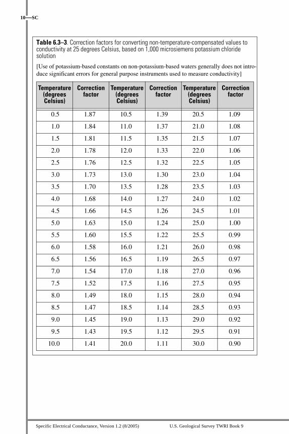
● For nontemperature-compensating conductivity instruments, apply a temperature-correction factor to convert the instrument reading to conductivity at 25°C.
● The correction factor depends to some degree on the specific instrument used—use the temperature-correction factor recom-mended by the manufacturer. If this is not available, use correc-tion factors from table 6.3–3.
● If an instrument cannot be adjusted to a known calibration stan-dard value, develop a calibration curve. After temperature com-pensation, if the percentage difference from the standard exceeds 5 percent, refer to the troubleshooting guide (section 6.3.4).
12. Record in the instrument log book and on field forms:
● The temperature of the standard solution.
● The known and the measured conductivity of the standard solu-tion (including ± variation).
● The temperature-correction factor (if necessary).
13. Discard the used standard into a waste container. Thoroughly rinse the sensor, thermometer, and container with deionized water.
14. Repeat steps 7 through 13 with the second conductivity standard.
● The purpose for measuring a second standard is to check instru-ment calibration over the range of the two standards.
● The difference from the standard value should not exceed 5 per-cent.
● If the difference is greater than 5 percent, repeat the entire cali-bration procedure. If the second reading still does not come within 5 percent of standard value, refer to the troubleshooting guide in section 6.3.4 or calibrate a backup instrument.
15. Record in the instrument log book and on field forms the calibration data for the second standard.
Do not use expired standards. Never reuse standards.
Specific Electrical Conductance, Version 1.2 (8/2005) U.S. Geological Survey TWRI Book 9
10—SC
Table 6.3–3. Correction factors for converting non-temperature-compensated values to conductivity at 25 degrees Celsius, based on 1,000 microsiemens potassium chloride solution
[Use of potassium-based constants on non-potassium-based waters generally does not intro-duce significant errors for general purpose instruments used to measure conductivity]
Temperature(degreesCelsius)
Correctionfactor
Temperature(degreesCelsius)
Correctionfactor
Temperature(degreesCelsius)
Correctionfactor
0.5 1.87 10.5 1.39 20.5 1.09
1.0 1.84 11.0 1.37 21.0 1.08
1.5 1.81 11.5 1.35 21.5 1.07
2.0 1.78 12.0 1.33 22.0 1.06
2.5 1.76 12.5 1.32 22.5 1.05
3.0 1.73 13.0 1.30 23.0 1.04
3.5 1.70 13.5 1.28 23.5 1.03
4.0 1.68 14.0 1.27 24.0 1.02
4.5 1.66 14.5 1.26 24.5 1.01
5.0 1.63 15.0 1.24 25.0 1.00
5.5 1.60 15.5 1.22 25.5 0.99
6.0 1.58 16.0 1.21 26.0 0.98
6.5 1.56 16.5 1.19 26.5 0.97
7.0 1.54 17.0 1.18 27.0 0.96
7.5 1.52 17.5 1.16 27.5 0.95
8.0 1.49 18.0 1.15 28.0 0.94
8.5 1.47 18.5 1.14 28.5 0.93
9.0 1.45 19.0 1.13 29.0 0.92
9.5 1.43 19.5 1.12 29.5 0.91
10.0 1.41 20.0 1.11 30.0 0.90
Chapter A6. Field Measurements Specific Electrical Conductance, Version 1.2 (8/2005)
SC—11
To extend the temperature range shown in table 6.3–3, consult the manufacturer’s guidelines. If these are unavailable, use the following equation:
where,C25= corrected conductivity value adjusted to 25°C;Cm = actual conductivity measured before correction; andtm = water temperature at time of Cm measurement.
MEASUREMENT 6.3.3In situ measurement generally is preferred for determining the con-ductivity of surface water; downhole or flowthrough-chamber mea-surements are preferred for ground water. Be alert to the following problems if conductivity is measured in an isolated (discrete) sample or subsample:
The conductivity of water can change over time as a result of chemical and physical processes such as precipitation, adsorption, ion exchange, oxidation, and reduction—Do not delay making conductivity measurements.
Field conditions (rain, wind, cold, dust, direct sunlight) can cause measurement problems—Shield the instrument to the extent possible and perform measurements in a collection chamber in an enclosed vehicle or an on-site laboratory.
For waters susceptible to significant gain and loss of dissolved gases, make the measurement within a gas-impermeable container (Berzelius flask) fitted with a stopper—Place the sensor through the stopper and work quickly to maintain the sample at ambient surface-water or ground-water temperature.
Avoid contamination from the pH electrode filling solution—Measure conductivity on a separate discrete sample from the one used for measuring pH; in a flowthrough chamber, position the conductivity sensor upstream of the pH electrode.
aehall
Sticky Note
The rounded constant 0.02 should be the value in Standard Methods (0.0191).
Specific Electrical Conductance, Version 1.2 (8/2005) U.S. Geological Survey TWRI Book 9
12—SC
Document the precision of your measurements. Precision should be determined about every tenth sample or more frequently, depending on study objectives. Successive measurements should be repeated until they agree within 5 percent at conductivity ≤ 100 μS/cm or within 3 percent at conductivity > 100 μS/cm.
The conductivity measurement reported must account for sample temperature. If using an instrument that does not automatically tem-perature compensate to 25°C, record the uncompensated measurement in your field notes, along with the corrected conductivity value. Use correction factors supplied by the instrument manufacturer if available; otherwise, refer to table 6.3–3.
Conductivity must be measured at the field site.
Surface-water conductivity should be measured in situ, if possible; oth-erwise, determine conductivity in discrete samples collected from a sample splitter or compositing device. Filtered samples may be needed if the concentrations of suspended material interfere with obtaining a stable measurement.
In situ measurement
Conductivity measurements in flowing surface water should represent the cross-sectional mean or median conductivity at the time of observa-tion (see step 7, below). Any deviation from this convention must be documented in the data base and with the published data.
First:Take a cross-sectional conductivity profile to determine the degree of system variability. A submersible sensor works best for this purpose.
Refer to NFM 6.0 for criteria to help decide which sampling method to use.
6.3.3.A SURFACE WATER
Chapter A6. Field Measurements Specific Electrical Conductance, Version 1.2 (8/2005)
SC—13
Next, follow the 7 steps listed below:1. Calibrate the conductivity instrument system at the field site after
equilibrating the buffers with stream temperature.
2. Record the conductivity variation from a cross-sectional profile on a field form and select the sampling method.
● Flowing, shallow stream—wade to the location(s) where con-ductivity is to be measured.
● Stream too deep or swift to wade—lower a weighted conduc-tivity sensor from a bridge, cableway, or boat. Do not attach weight to the sensor or the sensor cable.
● Still-water conditions—measure conductivity at multiple depths at several points in the cross section.
3. Immerse the conductivity and temperature sensors in the water to the correct depth and hold there (no less than 60 seconds) until the sensors equilibrate to water conditions.
4. Record the conductivity and corresponding temperature readings without removing the sensors from the water.
● Values should stabilize quickly to within 5 percent at conduc-tivity ≤100 μS/cm and within 3 percent at conductivity >100 μS/cm.
● Record the median of the stabilized values on field forms.
● If the readings do not meet the stability criterion after extend-ing the measurement period, record this difficulty in the field notes along with the fluctuation range and the median value of the last five or more readings.
5. For EWI or EDI measurements, proceed to the next station in the cross section and repeat steps 3 and 4. Record on field forms the mean (or median, if appropriate) value for each subsection mea-sured.
6. When the measurement is complete, remove the sensor from the water, rinse it with deionized water, and store it.
7. Record the stream conductivity on the field forms:
● In still water—median of three or more sequential values.
● EDI—mean value of all subsections measured (use the median if measuring one vertical at the centroid of flow).
● EWI—mean or median of all subsections measured (see NFM 6.0).
Specific Electrical Conductance, Version 1.2 (8/2005) U.S. Geological Survey TWRI Book 9
14—SC
Subsample measurement
Representative samples are to be collected and split or composited according to approved USGS methods (NFM 4). Measure the conduc-tivity of samples as soon as possible after collection. If the sample can-not be analyzed immediately, fill a bottle to the top, close it tightly, and maintain the sample at stream temperature until measurement.
Reported conductivity values normally are determined on an unfiltered sample. Large concentrations of suspended sediment can be a source of measurement error—record such conditions in the field notes.
If sediment concentrations are heavy, measure conductivity on both unfiltered and filtered subsamples and record both values on the field form.
If the conductivity value differs significantly between the filtered and unfiltered samples, report the filtered value as sample conductivity and identify it as a “filtered sample.”
1. Calibrate the conductivity instrument system at the field site.
2. Select the sampling method (see NFM 6.0) and collect a represen-tative sample.
3. Withdraw a homogenized subsample from a sample splitter or compositing device. Rinse the sample bottles three times with the sample—rinse them with sample filtrate, for filtered samples.
4. Rinse the conductivity sensor, the thermometer (liquid-in-glass or thermistor), and a container large enough to hold the dip-type sen-sor and the thermometer.
a. First, rinse the sensor, the thermometer, and the container three times with deionized water.
b. Next, rinse the sensor, the thermometer, and the container using sample water.
5. Allow the sensors to equilibrate to sample temperature, then dis-card the used sample water. Pour fresh sample water into a con-tainer holding the sensor and the thermometer. When using a dip-type sensor, do not let the sensor touch the bottom or sides of the measuring container.
Chapter A6. Field Measurements Specific Electrical Conductance, Version 1.2 (8/2005)
SC—15
6. Measure water temperature.
● If the conductivity sensor contains a calibrated thermistor, use this thermistor to measure water temperature.
● If the instrument is not temperature compensating, use a cali-brated thermistor or a liquid-in-glass thermometer.
● Adjust the instrument to the sample temperature (if necessary) and remove the thermometer.
7. Measure conductivity.
a. Remove any air trapped in the sensor by agitating the sensor up and down under the water surface.
b. Read the instrument display.
c. Agitate the sensor up and down under the water surface, and read the display again.
d. Repeat the procedure until consecutive readings are the same.
8. Record the conductivity and the sample temperature on field forms.
● If the instrument is not temperature compensating, record the raw data and convert the values to conductivity at 25°C using temperature-correction factors provided by the manufacturer.
● Report the median of the readings to three significant figures on the field forms.
● Discard the sample into a waste container and dispose accord-ing to regulations.
9. Quality control—
● Repeat steps 3 through 8 with at least two fresh subsamples, rinsing the instruments once only with sample water.
● Subsample values should be within ±5 percent for conductivity ≤100 μS/cm, or ±3 percent for conductivity >100 μS/cm.
● If criteria cannot be met: filter the samples, report the median of 3 or more samples, and record this difficulty in field notes.
10. Rinse the sensor, the thermometer, and the container with deion-ized water. If another measurement is to be made within the next day or two, store the sensor in deionized water. Otherwise, store the sensor dry.
Specific Electrical Conductance, Version 1.2 (8/2005) U.S. Geological Survey TWRI Book 9
16—SC
Measurements of ground-water conductivity must represent aquifer conditions. Temperature changes resulting from transporting a well sample to land surface can affect conductivity.
To minimize the effect from temperature changes, measure conductivity as close to the source as possible, using either a downhole or flowthrough-chamber sampling system (refer to NFM 6.0 for details).
Bailed or other methods for collecting discrete samples isolated from the source are not recommended as standard practice, although such methods are sometimes called for owing to site characteristics or other study requirements.
The well should be purged or in the process of purging before sample conductivity is determined and recorded.
Downhole and flowthrough-chamber measurement
1. Calibrate the conductivity instrument system on site.
● Bring standard solutions to the temperature of the water to be sampled by suspending the standards in a bucket into which well water is flowing. Allow at least 15 minutes for temperature equilibration. Do not contaminate standards with sample water.
a. Check the temperature of the water flowing into the bucket against that of standards.
b. Check that the thermometer (usually a thermistor function in the conductivity meter) has been certified within the past 4 months for the temperature range to be measured.
● After calibration, rinse the conductivity and temperature sen-sors thoroughly with deionized water.
2. Install the conductivity and temperature sensors.
● Downhole system—Lower the conductivity and temperature sensors to the sampling point, followed by the pump.
6.3.3.B GROUND WATER
Chapter A6. Field Measurements Specific Electrical Conductance, Version 1.2 (8/2005)
SC—17
a. Remove any air from the system by agitating the conductivity sensor up and down under the water; read the instrument display.
b. Repeat this procedure until rapid consecutive readings are approximately the same.
● Flowthrough-chamber system—Install the chamber system as close to the well as possible and shield the system from direct sunlight.
a. Position the conductivity sensor upstream from the pH electrode.
b. Direct flow to the chamber after an initial discharge to waste to clear sediment from sample line.
c. Release any air trapped in the chamber.d. Agitate the conductivity sensor up and down under the
water to remove air from system. Rapid consecutive readings should be about the same.
3. During purging (table 6.0–1 in NFM 6.0):
● Keep flow constant and laminar.
● Allow the sensors to equilibrate with ground-water tempera-ture for 5 minutes or more at the flow rate to be used for col-lecting all other samples.
4. Measure conductivity and associated temperature at regular inter-vals throughout purging; record the conductivity values and the associated temperature in the field notes.
● If the conductivity sensor contains a calibrated thermistor, use this thermistor to measure water temperature.
● If the instrument is not temperature compensating, install a cal-ibrated thermometer in the flowthrough chamber, record raw data, and apply correction factors.
5. Check the variability of the conductivity values toward the end of purging.
● The stability criterion is met when five readings taken at regu-larly spaced intervals of 3 to 5 minutes or more are within ±5 percent for conductivity ≤100 μS/cm ±3 percent for conductivity >100 μS/cm
Specific Electrical Conductance, Version 1.2 (8/2005) U.S. Geological Survey TWRI Book 9
18—SC
● When readings fluctuate rapidly, record the median of three or more readings within about 60 seconds as the value for a spe-cific time interval.
● If the criterion is not met, extend the purge period in accor-dance with study objectives and continue to record measure-ments at regularly spaced time intervals. Record this difficulty on the field forms.
6. Report conductivity.
● Record the final five values on field forms.
● Report the median value of the final five measurements as the sample conductivity.
● If values exceed the stability criterion, report the range of val-ues observed for the time interval, along with the median of the final five or more values.
Subsample measurement
Conductivity measurements reported from bailed or other discrete samples need to be identified in the data base, indicating the sampling method used. Refer to 6.0.3.B in NFM 6.0 for use of bailers and the subsample method.
1. Calibrate the conductivity instrument system onsite.
● Bring standard solutions to the temperature of the water to be sampled by suspending the standards in a bucket into which well water is flowing. Allow at least 15 minutes for tempera-ture equilibration. Do not contaminate standards with sample water.
a. Check the temperature of the water flowing into the bucket against that of standards.
b. Check that the thermometer (usually a thermistor function in the conductivity meter) has been certified within the past 4 months for the temperature range to be measured.
● After calibration, rinse the conductivity and temperature sen-sors thoroughly with deionized water.
Chapter A6. Field Measurements Specific Electrical Conductance, Version 1.2 (8/2005)
SC—19
2. Draw off subsamples for measurement.
● Quality control—Collect three subsamples to check pre-cision.
● If samples need to be stored for a short time, or if several subsamples will be measured, collect sample aliquots in separate field-rinsed bottles—fill to the brim, cap tightly, and maintain at ambient ground-water temperature. Mea-sure conductivity as soon as possible.
3. Follow procedures described in steps 4 through 10 for “Subsample measurement” of surface water (6.3.3.A).
TECHNICAL NOTE: If the sample is measured in an open container and readings do not stabilize within several minutes, the cause may be CO2 degassing—use a closed system to measure the sample. Filter the conductivity sample if the settling of clay particles appears to interfere with the stability of the readings.
Contact the instrument manufacturer if the actions suggested in table 6.3–4 fail to resolve the problem.
If available, use a commercial, electronic calibrator to check the function of conductivity instruments.
Check the voltage of batteries. Always have good batteries in instruments and carry spares.
TROUBLESHOOTING 6.3.4
Specific Electrical Conductance, Version 1.2 (8/2005) U.S. Geological Survey TWRI Book 9
• Standards may be old or contaminated—use fresh standards.
• Electrodes dirty—clean with a detergent solution, then with 5 percent HCl. Before using any acid solution to remove resistant residues, check manufacturer’s guidelines.
• Air trapped in conductivity sensor—agitate sensor up and down to expel trapped air.
• Weak batteries—replace.• Temperature compensation incorrect—ensure
that thermometer is operating properly and is calibrated.
• Sensor constant incorrect—replace sensor.
Erratic instrument readings
• Loose or defective connections—tighten or replace.
• Broken cables—repair or replace.• Air trapped in conductivity sensor—agitate
sensor up and down to expel trapped air.• Rapid changes in water temperature—measure
in situ.• Outgassing of ground-water sample—use a
downhole instrument; if unavailable, use a flowthrough chamber.
• Broken sensor—replace.
Instrument requires frequent recalibration
• Temperature compensator not working—measure conductivity of a solution. Place solution in a water bath and raise solution temperature to about 20ºC. Measure conductivity again, allowing sufficient time for temperature of conductivity sensor to equilibrate to temperature of solution. If the two values differ by 5 percent or more, replace conductivity sensor.
Chapter A6. Field Measurements Specific Electrical Conductance, Version 1.2 (8/2005)
SC—21
REPORTING 6.3.5
Report routine conductivity measurements to three significant fig-ures, whole numbers only, in microsiemens per centimeter at 25°C.
Record the accuracy range of the instrument system in the data base, if possible, and always report it with published values.
Enter field-determined conductivity measurements on the NWQL Analytical Services Request form using the correct parameter code.
Specific Electrical Conductance, Version 1.2 (8/2005) U.S. Geological Survey TWRI Book 9
22—SC
SELECTED REFERENCES
American Public Health Association, American Water Works Association, and Water Environment Federation, 2001, Standard methods for the examination of water and wastewater (20th ed.): Washington, D.C., American Public Health Association, p. 2–43 to 2–48.
American Society for Testing and Materials, 1977, Standard test methods for electrical conductivity and resistivity of water, No. D 1125–77: Philadelphia, American Society for Testing and Materials, p. 138–146.
Brown, Eugene, Skougstad, M.W., and Fishman, M.J., 1970, Methods for collection and analysis of water samples for dissolved minerals and gases: U.S. Geological Survey Techniques of Water-Resources Investigations, book 5, chap. A1, p. 148–150.
Fishman, M.J., and Friedman, L.C., eds., 1989, Methods for determination of inorganic substances in water and fluvial sediments: U.S. Geological Survey Techniques of Water-Resources Investigations, book 5, chap. A1, p. 461–463.
Hem, J.D., 1982, Conductance—a collective measure of dissolved ions, in Minear, R.A., and Keith, L.H., eds., Water analysis, v. 1, inorganic species, pt. 1: New York, Academic Press, p. 137–161.
______ 1985, Study and interpretation of chemical characteristics of natural water (3d ed.): U.S. Geological Survey Water-Supply Paper 2254, p. 66–69.
Rainwater, F.H., and Thatcher, L.L., 1960, Methods for collection and analysis of water samples: U.S. Geological Survey Water-Supply Paper 1454, p. 275–278.
Roberson, C.E., Feth, J.H., Seaber, P.R., and Anderson, Peter, 1963, Differences between field and laboratory determinations of pH, alkalinity, and specific conductance of natural water: U.S. Geological Survey Professional Paper 475– C, p. C212–C215.
U.S. Geological Survey, variously dated, National field manual for the collection of water-quality data: U.S. Geological Survey Techniques of Water-Resources Investigations, book 9, chaps. A1-A9, available online at http://pubs.water.usgs.gov/twri9A.
Wilde, F.D., Radtke, D.B., Gibs, Jacob, and Iwatsubo, R.T., eds., September 1999, Collection of water samples: U.S. Geological Survey Techniques of Water-Resources Investigations, book 9, chap. A4, accessed Sept. 20, 2005 at http://pubs.water.usgs.gov/twri9A4/
Wood, W.W., 1981, Guidelines for collection and field analysis of ground-water samples for selected unstable constituents: U.S. Geological Survey Techniques of Water-Resources Investigations, book 1, chap. D2, p. 11.


![[PPT]Chapter 18: Electrical Properties - Memorial …asharan/courses/3911_LECTURES/ch18.ppt.pptx · Web view• How are electrical conductance and resistance characterized? • What](https://static.documents.pub/doc/80x56/5b0c7e1a7f8b9a8b038c3a86/pptchapter-18-electrical-properties-memorial-asharancourses3911lecturesch18pptpptxweb.jpg)


