International Journal of Industrial Engineering and Technology.
ISSN 0974-3146 Volume 9, Number 1 (2017), pp. 23-45
© International Research Publication House
http://www.irphouse.com
Performance Evaluation for Super Alloy (Ni-Cr)
Designed Structural Assembly of Gas Turbine Using
Component Mode Synthesis
Kalapala Prasad1, B. Anjaneya Prasad2,M. Anandarao3,
1Asst.professor, department Mech Engg., UCEK, JNTU Kakinada, Andhra Pradesh, India.
2Professor&Directorof Evaluation, Mechanical Engineering, JNTUH College of Engineering Hyderabad (Autonomous),
Andhra Pradesh, India.
3Professor &Principal of M.L.R.I.T, Hyderabad, India.
Abstract
A prototype model for gas turbine has been fabricated underthe
experimental and theoretical investigation are carried out. The
configuration of the model consists of (1) Blades (2) Disc / Hub
(3)Rotor / Shaft. Among the parts Blades and Disc are made of Ni – Cr
Alloy. And rotor is made of mild steel. Blades are twisted aerofoil shape.In
this the mass moment of inertia, torsional stiffness and polar moments of
inertia are calculated for the integral unit of gas turbine with the using of the
principles of mechanical vibrations. By employing CMS approach, the design
parameters such as (1) Natural frequency (2) Damping factor (3) Logarithmic
decrement are obtained by applying this methodology, an attempt is made to
identify the parameters for the stability criteria. They are comprehensively
studied and their effect on individual parameters onthe stability is analyzed.A
through discussion on the results obtained in this investigation are presented in
this paper. Along with the Experimental results have also been compared with
those of theoretical calculations.
24 Kalapala Prasad, B. Anjaneya Prasad and M. Anandarao
Keywords: Torsional stiffness, Damping factor, FFT analyzer, natural
frequency, Twisted aerofoil blade, Holzer’s method.
NOMENCLATURE
ωn = Natural frequency
ԑ = Damping factor
δ = Logarithmic decrement
FFT = Fast Fourier Transform
Xa = Minimum amplitude
Xb = Maximum amplitude
Kt = Tensional stiffens
J = Mass Moment of Inertia
G = Shear Modulus
Ip= Polar moment of Inertia
L = Length
M = Mass
r = Radius
d = Diameter
rO = outside radius of Hub.
ri = inside radius of Hub.
P = the distance between x and x ̅
q = the distance between y and y̅
BBW = Bottom Base Width
TBW = Top Base Width
d1 = Inside diameter of hub
d2 = out side diameter of hub
Performance Evaluation for Super Alloy (Ni-Cr) Designed Structural Assembly 25
INTRODUCTION
A gas turbine, also called a combustion turbine, also called a combustion turbine, is a
type of rotary machine, used to produce power. It is the heart of power plant that
produces electric current. It converts natural gas or other liquid fuels energy to
mechanical energy.Prediction of natural frequencies of vibration is of considerable
importance at the design stage of a turbine blade. The theoretical solution for natural
frequencies of a stationery uniform cantilever beam is well known. The actual
problem of a turbine blade is rather complicated and one has to consider several
factors, like (1)Speed of rotation (2)disc radius(3)Twist of blade(4)Taper of the
blade(5)Tip mass(6) Shear deflection and rotary inertia.In order to analyse the
vibrations that are induced, experimentally mathematical as well as simulation is
carried out in ANSYS 15.0 soft ware. The numerical approach is made by using the
CMS approach.
A super alloy (or) high performance alloy is an alloy that exhibits several key
characteristics excellent mechanical strength, resistance to thermal creep deformation.
It has good surface stability and resistance to corrosion or oxidation. The crystal
structure is face centred cubic austenitic. Super alloys develop high temperature
strength through solid solution strengthening. Oxidation of corrosion resistance is
provided by elements such as aluminium and chromium. The primary applications of
such alloys are turbine engines, both aerospace and marine. Ni-based super alloys are
excellent high temperature materials and have proven veryuseful. Ni-based super
alloys are superior hot corrosion, oxidation and wear resistance compared to Ni-based
super alloys. Ni-based alloys are used in load-bearing structures. Also we can say
super alloy has high melting point. In this way it is high temperature sustainable.
Super alloy is also good having reliability (or) durability. In this way super alloy is
superior when compared to aluminium alloy.
In general the turbine blade materials used are Nickel chromium alloy, Inconel,
titanium, Aluminium alloy. The natural frequency is found for each material at
different modes using both numerical & simulation approach.
Gas turbines have a wide range of applications including air crafts, power plants,
marine application etc., So there is a immediate need to minimize the vibrations
induced in the structural assembly of gas turbine.
LITERATURE REVIEWON CMS
1. M.H.Liu and G.T.Zheng proposed and improved technique of the component
mode synthesis for non classically damped systems, with the second order
approximation. It is based on free interface vibration modes and residual
attachment modes with dynamic effects of the trunctuated modes.
26 Kalapala Prasad, B. Anjaneya Prasad and M. Anandarao
2. Klaus-jurgen Bathe and jian Dong has presented an approach to improve
component mode synthesis solution using subspace iterations to obtain
frequency and mode shape prediction of controlled accuracy. In traditional
CMS method the obtained values have an error and this error can be
minimized by using subspace iteration methods.
3. Rainer Nordmamn and Ericknopf has outlined the effected of natural
frequencies if a rotor with flexible blades are predicted by coupling and
modal properties of two or more subsystems: The rotor with rigid blades and
the violated flexible blade rows.
4. C.FARH AT and M. GERADINT has constructed a substructure Interface
impedance operator and present a spectral analysis that demonstrates that the
method of Craig and Bampton (CB) is the most natural CMS method and then
consider the CB method for assesmbling hetreogeneous substructures and
recast it into a hybrid vibrational formulation.
5. Robert J Kuether and Matlhew S Allen formulated the efficiency of craig-
Bampton approach for two example problems, one that couples two
geometrically nonlinear beams at a shared rotational degree of freedom and
another that couples an axial spring element to the axial DOF of a geometrical
nonlinear beam.
6. A Batailly, M Legrand, P.Cartraud and C.Pierre Investigated the general
behaviour of such approach in the presence of contact nonlinearities. It will be
shown that in our contact case a good accuracy can be obtained from a
reduced models with very limited number of modes.
7. Adam butland, Dr. Peteravitable extends the methodology to include test data
for the components models. A typical test case is shown to illustrate the
results. The results shown that this technique can be very accurate in the
development of reduced order test verified Craig-Brampton CMS models.
8. G.A.Choy and Yang proposed the combine optimization algorithm, immune
genetic algorithm for multi optimization problem by introducing the capability
of the immune system to the GA and also applied to minimize the total weight
of the short and the transmitted forces at the bearings.
9. Rao and Kolla etal presented the optimum value of efficiency and may of the
axial flow gas turbine stage using genetic algorithm approach.
10. Dr.S.Vjayarangam, V.Alagappam and I.Rajendren presented a formulation
and technique using GA for design optimization of leaf springs in which
dimensions of leaf spring are optimized.
11. Oh and Kim developed a conceptual design optimisation code to minimize the
fluid dynamic losses in mixed flow pump Impellers.
Performance Evaluation for Super Alloy (Ni-Cr) Designed Structural Assembly 27
12. William Carnegie discussed the vibrate of pretwisted Cantilever blade and
pred the frequencies of vibration.
13. Rao and Srinivas investigated the flean torsional vibrations of a linearly tape
twisted flexible blade, rotationally constrained out an arbitrary position along
the length of blade using neural networks to identify the location of the modal
an optimum point for a given blade taper ration and root flexibility parameter
so as to maximixe the fundamental frequency.
14. Rao and Srinivas considered the implementation of neural networks to system
identification and vibration suppression of bladed rotor time records of
displacement and velocity at a point on the blade two novel methods are
employed for the stage optimization problem and sufficiently accurate results
are arrived when compared with available data.
1. Turbine Hub:-
Figure-1
Material : Nickel- Chromium
Length = 85 mm
Mass = 2.4 Kg
Shear Modulus (G) = 162 N/mm2
Density = 8470 Kg/m3
𝑃𝑜𝑙𝑎𝑟 𝑀𝑜𝑚𝑒𝑛𝑡 𝑜𝑓 𝐼𝑛𝑒𝑟𝑡𝑖𝑎 𝐼𝑝 =𝜋
32[𝑑1
4 − 𝑑24]
= 17.155 × 10⁶𝑚𝑚4
𝑰𝒑 = 𝟏𝟕. 𝟏𝟓𝟓 × 𝟏𝟎𝟔𝒎𝒎𝟒
28 Kalapala Prasad, B. Anjaneya Prasad and M. Anandarao
𝑇𝑜𝑟𝑠𝑖𝑜𝑛𝑎𝑙 𝑆𝑡𝑖𝑓𝑓𝑛𝑒𝑠𝑠 𝐾𝑡 =𝐺𝐼𝑝
𝐿
=162 𝑋 17.15 𝑋
610
85
= 32.7 × 10⁶𝑁. 𝑚𝑚
From the component mode synthesis Torsional stiffness value of hub we have divided
into two parts
𝐾𝑡1 = 𝐾𝑡2 =32.7 ×10⁶𝑁.𝑚𝑚
2
𝑲𝒕𝟏 = 𝑲𝒕𝟐 = 𝟏𝟔. 𝟑𝟓 𝑵. 𝒎𝒎
𝑀𝑎𝑠𝑠 𝑚𝑜𝑚𝑚𝑒𝑛𝑡 𝑜𝑓 𝐼𝑛𝑒𝑟𝑡𝑖𝑎 𝐽 =1
2𝑚(𝑟1
2 − 𝑟22)
= 3.84 × 10³𝐾𝑔. 𝑚𝑚2
From the component mode synthesis mass moment of inertia is divided into two parts
we have
𝐽1 = 𝐽2 =3.84×10³𝐾𝑔.𝑚𝑚2
2
𝑱𝟏 = 𝑱𝟐 = 𝟏. 𝟗𝟐 × 𝟏𝟎𝟑𝑲𝒈. 𝒎𝒎𝟐
𝑱𝟏 = 𝑱𝟐 = 𝟏. 𝟗𝟐 × 𝟏𝟎𝟑𝑲𝒈. 𝒎𝒎𝟐
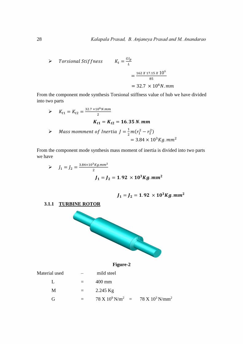
3.1.1 TURBINE ROTOR
Figure-2
Material used – mild steel
L = 400 mm
M = 2.245 Kg
G = 78 X 109 N/m2 = 78 X 103 N/mm2
Performance Evaluation for Super Alloy (Ni-Cr) Designed Structural Assembly 29
𝑃𝑜𝑙𝑎𝑟 𝑀𝑜𝑚𝑒𝑛𝑡 𝑜𝑓 𝐼𝑛𝑒𝑟𝑡𝑖𝑎 𝐼𝑝 =𝜋
32𝑑4
𝑰𝒑 = 𝟏𝟓. 𝟕𝟏 × 𝟏𝟎𝟑𝒎𝒎𝟒
𝑇𝑜𝑟𝑠𝑖𝑜𝑛𝑎𝑙 𝑆𝑡𝑖𝑓𝑓𝑛𝑒𝑠𝑠 𝐾𝑡 =𝐺𝐼𝑝
𝐿
=78 × 103 × 15.71 × 103
400
= 3.06 𝑁. 𝑚𝑚
With reference of component mode synthesis Torsional stiffness value of rotor is
divided into two parts we have
𝐾𝑡3 = 𝐾𝑡4 =3.06 𝑁.𝑚𝑚
2
𝑲𝒕𝟑 = 𝑲𝒕𝟒 = 𝟏. 𝟓𝟑 × 𝟏𝟎𝟔 𝑵. 𝒎𝒎
𝑀𝑎𝑠𝑠 𝑚𝑜𝑚𝑚𝑒𝑛𝑡 𝑜𝑓 𝐼𝑛𝑒𝑟𝑡𝑖𝑎 𝐽 =1
2𝑚𝑟2
= 112.25 𝑘𝑔. 𝑚𝑚2
According to component mode synthesis mass moment of inertia of rotor is divided
into two components we have
𝐽3 = 𝐽4 =112.25
2 𝑘𝑔. 𝑚𝑚2
𝑱𝟑 = 𝑱𝟒 = 𝟓𝟔. 𝟏𝟐𝟓 𝒌𝒈. 𝒎𝒎𝟐
3.1.2 Twisted Aerofoil/Blade :-
ρ = 8470 Kg/m3
G = 162 N/m2
b = 60 mm
l = 200 mm
q = 30 mm
Figure-3
From trapezoid section of a blade to establish the mathematical expression we have
𝑃𝑜𝑙𝑎𝑟 𝑀𝑜𝑚𝑒𝑛𝑡 𝑜𝑓 𝐼𝑛𝑒𝑟𝑡𝑖𝑎 𝐼𝑝 =𝑑3(𝑎2+4𝑎𝑏+𝑏2)
36(𝑎+𝑏)
30 Kalapala Prasad, B. Anjaneya Prasad and M. Anandarao
=2003(602 + 4 (60) (80) + 802)
36(80 + 60)
𝑰𝒑 = 𝟒𝟔. 𝟑𝟓 × 𝟏𝟎𝟔 𝒎𝒎𝟒
𝑇𝑜𝑟𝑠𝑖𝑜𝑛𝑎𝑙 𝑆𝑡𝑖𝑓𝑓𝑛𝑒𝑠𝑠 𝐾𝑡 =pIG.
𝐿
=162 × 46.35 × 106 × 10−12
200 × 10−3
𝐾𝑡 = 37.54 × 10⁶ 𝑁. 𝑚𝑚 (𝐹𝑜𝑟 𝑆𝑖𝑛𝑔𝑙𝑒 𝐵𝑙𝑎𝑑𝑒)
𝐾𝑡 = 225.261 × 10⁻³ 𝑁. 𝑚𝑚 (𝐹𝑜𝑟 𝑆𝑖𝑥 𝐵𝑙𝑎𝑑𝑒)
By the application of component mode synthesis Torsional stiffness of a blade
is divided into two parts we have
𝑲𝒕𝟓 = 𝑲𝒕𝟔 = 𝟏𝟏𝟐. 𝟔 × 𝟏𝟎𝟔𝑵. 𝒎𝒎
Left Side Triangular Section of blade:-
Figure-4
𝑀𝑎𝑠𝑠 𝑚𝑜𝑚𝑚𝑒𝑛𝑡 𝑜𝑓 𝐼𝑛𝑒𝑟𝑡𝑖𝑎 𝐽𝐼 = 𝑚 [ℎ2+𝑙2
18+ 𝑞2 + 𝑟2]
= 0.693 [102 + 2002
18+ (
10
3)
2
+ (200
3)
2
]
𝐽𝐼 = 4.63 × 10³𝐾𝑔. 𝑚𝑚2
Performance Evaluation for Super Alloy (Ni-Cr) Designed Structural Assembly 31
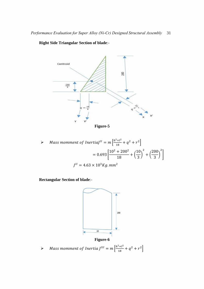
Right Side Triangular Section of blade:-
Figure-5
𝑀𝑎𝑠𝑠 𝑚𝑜𝑚𝑚𝑒𝑛𝑡 𝑜𝑓 𝐼𝑛𝑒𝑟𝑡𝑖𝑎𝐽𝐼𝐼 = 𝑚 [ℎ2+𝑙2
18+ 𝑞2 + 𝑟2]
= 0.693 [102 + 2002
18+ (
10
3)
2
+ (200
3)
2
]
𝐽𝐼𝐼 = 4.63 × 10³𝐾𝑔. 𝑚𝑚2
Rectangular Section of blade:-
Figure-6
𝑀𝑎𝑠𝑠 𝑚𝑜𝑚𝑚𝑒𝑛𝑡 𝑜𝑓 𝐼𝑛𝑒𝑟𝑡𝑖𝑎 𝐽𝐼𝐼𝐼 = 𝑚 [ℎ2+𝑙2
18+ 𝑞2 + 𝑟2]
32 Kalapala Prasad, B. Anjaneya Prasad and M. Anandarao
= 0.693 [602 + 2002
18+ 302 + 1002]
𝐽𝐼𝐼𝐼 = 9.2 × 10³𝐾𝑔. 𝑚𝑚2
Mass moment of Inertia of Blade
𝐽 = 𝐿𝑒𝑓𝑡 𝑇𝑟𝑖𝑎𝑛𝑔𝑙𝑒 𝑆𝑒𝑐𝑡𝑖𝑜𝑛 + 𝑅𝑖𝑔ℎ𝑡 𝑇𝑟𝑖𝑎𝑛𝑔𝑙𝑒 𝑆𝑒𝑐𝑡𝑖𝑜𝑛 + 𝑅𝑒𝑐𝑎𝑛𝑔𝑙𝑒
= 18.46 × 10⁶ 𝐾𝑔. 𝑚𝑚2(𝐹𝑜𝑟 𝑆𝑖𝑛𝑔𝑙𝑒 𝐵𝑙𝑎𝑑𝑒)
𝐽 = 110.76 × 10³ 𝐾𝑔. 𝑚𝑚2 (𝐹𝑜𝑟 𝑆𝑖𝑥 𝐵𝑙𝑎𝑑𝑒)
Mass moment of inertia of blade is divided into 3 parts we have
𝐽 =110.76 × 10³
3𝐾𝑔. 𝑚𝑚2
𝑱𝟓 = 𝑱𝟔 = 𝑱𝟕 = 𝟑𝟔. 𝟕𝟐 × 𝟏𝟎𝟑 𝑲𝒈. 𝒎𝒎𝟐
Table: 1
HUB ROTOR BLADE
Polar Moment of
Inertia (Ip) mm4 17.155 × 10⁶ 15.71 × 103mm4 46.35 × 10⁶
Torsional
Stiffness(Kt) 𝑁. 𝑚𝑚
16.35 × 10⁶ 1.53 × 10⁶ 𝑁. 𝑚𝑚 112.6 × 10⁶
16.35 × 10⁶ 1.53 × 10⁶ 𝑁. 𝑚𝑚 112.6 × 10⁶
Mass Moment of
Inertia (J) 𝐾𝑔. 𝑚𝑚2
1.92 × 10³ 56.125 × 10⁶ 36.92 × 10³
36.92 × 10³
1.92 × 10³ 56.125 × 10⁶ 36.92 × 10³
Figure-7
Performance Evaluation for Super Alloy (Ni-Cr) Designed Structural Assembly 33
DETERMINATION OF NATURAL MODE VALUES
1. Turbine Hub :
𝑇𝑜𝑟𝑠𝑖𝑜𝑛𝑎𝑙 𝑆𝑡𝑖𝑓𝑓𝑛𝑒𝑠 𝐾𝑡 = [𝐾𝑡1 −𝐾𝑡1
−𝐾𝑡1 𝐾𝑡1 + 𝐾𝑡2]
= [ 16.35 × 10⁶ −16.35 × 10⁶
−16.35 × 10⁶ 32.7 × 10⁶ ] 𝑁. 𝑚𝑚
𝑀𝑎𝑠𝑠 𝑀𝑜𝑚𝑒𝑛𝑡 𝑜𝑓 𝐼𝑛𝑒𝑟𝑡𝑖𝑎 𝐽 = [𝐽1 00 𝐽2
]
= [1.92 × 10³ 00 1.92 × 10³] 𝐾𝑔. 𝑚𝑚2
The Characteristic Equation has [𝐾𝑡 − 𝐽𝑤2 ]{𝑋} = 0
Then |𝐾𝑡 − 𝐽𝑤2 | = 0
|16.35 × 10³ − 1.92 × 10⁻³𝜔2 −16.35 × 10³
−16.35 × 10³ 32.7 × 10³ − 1.92 × 10⁻³𝜔2| = [00
]
534.645 × 10⁶ − 31.392𝜔2 − 62.784𝜔2 + 3.686 × 10⁻⁶𝜔4 − 267.32 × 106 = 0
𝐿𝑒𝑡 𝜔2 = 𝜆
𝟑. 𝟔𝟖𝟔 × 𝟏𝟎−𝟔𝝀𝟐 − 𝟗𝟒. 𝟏𝟕𝟔𝝀 + 𝟐𝟔𝟕. 𝟑𝟐𝟓 × 𝟏𝟎𝟔 = 𝟎
Use this formula for finding roots fro above Quadratic equation 𝜆1,2 =−𝑏±√𝑏2−4𝑎𝑐
2𝑎
𝜆1,2 =−(−94.176)±√(−94.176)2−(4 × 3.686 ×10−6)(267.325 ×10⁶)
2 × 3.686 × 10−6
𝜆1,2 = 22.27 × 10⁶, 3.25 × 10⁶
𝜔12 = 𝜆1 = 22.3 × 10⁶
𝜔22 = 𝜆2 = 3.25 × 10⁶
Substitute 𝜔12 = 𝜆1 = 22.3 × 10⁶ in [𝐾𝑡 − 𝐽𝑤
2 ]{𝑋} = 0 then
[16.34 × 10³ − (22.3 × 106 × 1.92 × 10−3) −16.34 × 10³
−16.34 × 10³ 32.69 × 10³ − (22.3 × 106 × 1.92 × 10−3)] [
𝑋1
𝑋2
] = [0
0]
[−26.418 × 10³ −16.34 × 10³
−16.34 × 10³ −10.06 × 10³] [𝑋1
𝑋2] = [
00
]
34 Kalapala Prasad, B. Anjaneya Prasad and M. Anandarao
−26.4148 × 10³𝑋1 − 16.34 × 10³𝑋2 = 0
−16.34 × 10³𝑋1 − 10.06 × 10³𝑋2 = 0
𝑰𝒇 𝑿𝟐 = 𝟏 𝒕𝒉𝒆𝒏 𝑿𝟏 = 𝟎. 𝟔𝟏𝟖
Substitute 𝜔22 = 𝜆2 = 1.04 × 10¹⁰ in [𝐾𝑡 − 𝐽𝑤
2 ]{𝑋} = 0 then
[16.34 × 10³ − (3.25 × 106 × 1.92 × 10−3) −16.34 × 10³
−16.34 × 10³ 32.69 × 10³ − (3.25 × 106 × 1.92 × 10−3)] [
𝑋1
𝑋2] = [
00
]
[ 10.1 × 10³ −16.34 × 10³
−16.34 × 10³ 26.45 × 10³ ] [𝑋1
𝑋2] = [
00
]
10.1 × 10³𝑋1𝐼 − 16.34 × 10³𝑋2
𝐼 = 0
−16.34 × 10³𝑋1𝐼 + 26.45 × 10³𝑋2
𝐼 = 0
𝑰𝒇 𝑿𝟏𝑰 = 𝟏 𝒕𝒉𝒆𝒏 𝑿𝟐
𝑰 = 𝟎. 𝟔𝟏𝟖
2. Rotor :-
𝑇𝑜𝑟𝑠𝑖𝑜𝑛𝑎𝑙 𝑆𝑡𝑖𝑓𝑓𝑛𝑒𝑠 𝐾𝑡 = [𝐾𝑡3 −𝐾𝑡3
−𝐾𝑡3 𝐾𝑡3 + 𝐾𝑡4]
= [ 153.15 × 10⁴ −153.15 × 10⁴
−153.15 × 10⁴ 306.3 × 10⁴ ] 𝑁. 𝑚𝑚
𝑀𝑎𝑠𝑠 𝑀𝑜𝑚𝑒𝑛𝑡 𝑜𝑓 𝐼𝑛𝑒𝑟𝑡𝑖𝑎 𝐽 = [𝐽3 00 𝐽4
]
= [0.56 × 10⁻⁴ 00 0.56 × 10⁻⁴]
The Characteristic Equation has [𝐾𝑡 − 𝐽𝑤2 ]{𝑋} = 0
Then |𝐾𝑡 − 𝐽𝑤2 | = 0
[153.15 × 10⁴ − 0.56 × 10⁻⁴𝜔2 −153.15 × 10⁴
−153.15 × 10⁴ 306.3 × 10⁴ − 0.56 × 10⁻⁴𝜔2] = [00
]
46909.84 × 108 − (85.764 + 171.528)𝜔2 + 0.313 × 10⁻⁸𝜔4 − 234.54 × 108 = 0
𝐿𝑒𝑡 𝜔2 = 𝜆
𝟎. 𝟑𝟏𝟑 × 𝟏𝟎−𝟖𝝀𝟐 − 𝟐𝟓𝟕. 𝟐𝟗𝟐𝝀 + 𝟐𝟑𝟒𝟓𝟓. 𝟖 × 𝟏𝟎𝟖 = 𝟎
Performance Evaluation for Super Alloy (Ni-Cr) Designed Structural Assembly 35
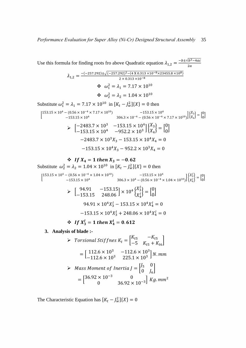
Use this formula for finding roots fro above Quadratic equation 𝜆1,2 =−𝑏±√𝑏2−4𝑎𝑐
2𝑎
𝜆1,2 =−(−257.292)±√(−257.292)2−(4 X 0.313 ×10−8×23455.8 ×108)
2 × 0.313 ×10−8
𝜔12 = 𝜆1 = 7.17 × 10¹⁰
𝜔22 = 𝜆2 = 1.04 × 10¹⁰
Substitute 𝜔12 = 𝜆1 = 7.17 × 10¹⁰ in [𝐾𝑡 − 𝐽𝑤
2 ]{𝑋} = 0 then
[153.15 × 10⁴ − (0.56 × 10−4 × 7.17 × 1010) −153.15 × 10⁴
−153.15 × 10⁴ 306.3 × 10⁻⁴ − (0.56 × 10−4 × 7.17 × 1010)] {
𝑋3
𝑋4} = [
00
]
[−2483.7 × 103 −153.15 × 10⁴
−153.15 × 10⁴ −952.2 × 10³ ] {𝑋3
𝑋4} = [
00
]
−2483.7 × 103𝑋3 − 153.15 × 10⁴𝑋4 = 0
−153.15 × 10⁴𝑋3 − 952.2 × 10³𝑋4 = 0
𝑰𝒇 𝑿𝟒 = 𝟏 𝒕𝒉𝒆𝒏 𝑿𝟑 = −𝟎. 𝟔𝟐
Substitute 𝜔22 = 𝜆2 = 1.04 × 10¹⁰ in [𝐾𝑡 − 𝐽𝑤
2 ]{𝑋} = 0 then
[153.15 × 10⁴ − (0.56 × 10−4 × 1.04 × 1010) −153.15 × 10⁴
−153.15 × 10⁴ 306.3 × 10⁴ − (0.56 × 10−4 × 1.04 × 1010)] {
𝑋3𝐼
𝑋4𝐼} = [
00
]
[94.91 −153.15
−153.15 248.06] × 104 {
𝑋3𝐼
𝑋4𝐼} = [
00
]
94.91 × 10⁴𝑋3𝐼 − 153.15 × 10⁴𝑋4
𝐼 = 0
−153.15 × 10⁴𝑋3𝐼 + 248.06 × 10⁴𝑋4
𝐼 = 0
𝑰𝒇 𝑿𝟑𝑰 = 𝟏 𝒕𝒉𝒆𝒏 𝑿𝟒
𝑰 = 𝟎. 𝟔𝟏𝟐
3. Analysis of blade :-
𝑇𝑜𝑟𝑠𝑖𝑜𝑛𝑎𝑙 𝑆𝑡𝑖𝑓𝑓𝑛𝑒𝑠 𝐾𝑡 = [𝐾𝑡5 −𝐾𝑡5
−5 𝐾𝑡5 + 𝐾𝑡6]
= [ 112.6 × 10³ −112.6 × 10³
−112.6 × 10³ 225.1 × 10³ ] 𝑁. 𝑚𝑚
𝑀𝑎𝑠𝑠 𝑀𝑜𝑚𝑒𝑛𝑡 𝑜𝑓 𝐼𝑛𝑒𝑟𝑡𝑖𝑎 𝐽 = [𝐽5 00 𝐽6
]
= [36.92 × 10⁻³ 00 36.92 × 10⁻³] 𝐾𝑔. 𝑚𝑚2
The Characteristic Equation has [𝐾𝑡 − 𝐽𝑤2 ]{𝑋} = 0
36 Kalapala Prasad, B. Anjaneya Prasad and M. Anandarao
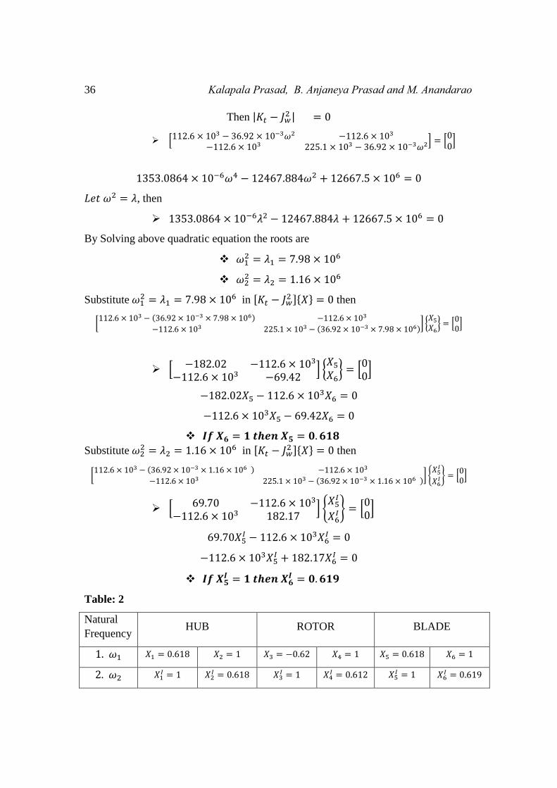
Then |𝐾𝑡 − 𝐽𝑤2 | = 0
[112.6 × 10³ − 36.92 × 10⁻³𝜔2 −112.6 × 10³
−112.6 × 10³ 225.1 × 10³ − 36.92 × 10⁻³𝜔2] = [00
]
1353.0864 × 10−6𝜔4 − 12467.884𝜔2 + 12667.5 × 106 = 0
𝐿𝑒𝑡 𝜔2 = 𝜆, then
1353.0864 × 10−6𝜆2 − 12467.884𝜆 + 12667.5 × 106 = 0
By Solving above quadratic equation the roots are
𝜔12 = 𝜆1 = 7.98 × 10⁶
𝜔22 = 𝜆2 = 1.16 × 10⁶
Substitute 𝜔12 = 𝜆1 = 7.98 × 10⁶ in [𝐾𝑡 − 𝐽𝑤
2 ]{𝑋} = 0 then
[112.6 × 10³ − (36.92 × 10−3 × 7.98 × 106) −112.6 × 10³
−112.6 × 10³ 225.1 × 10³ − (36.92 × 10−3 × 7.98 × 106)] {
𝑋5
𝑋6} = [
00
]
[ −182.02 −112.6 × 10³
−112.6 × 10³ −69.42] {
𝑋5
𝑋6} = [
00
]
−182.02𝑋5 − 112.6 × 10³𝑋6 = 0
−112.6 × 10³𝑋5 − 69.42𝑋6 = 0
𝑰𝒇 𝑿𝟔 = 𝟏 𝒕𝒉𝒆𝒏 𝑿𝟓 = 𝟎. 𝟔𝟏𝟖
Substitute 𝜔22 = 𝜆2 = 1.16 × 10⁶ in [𝐾𝑡 − 𝐽𝑤
2 ]{𝑋} = 0 then
[112.6 × 10³ − (36.92 × 10−3 × 1.16 × 106 ) −112.6 × 10³
−112.6 × 10³ 225.1 × 10³ − (36.92 × 10−3 × 1.16 × 106 )] {
𝑋5𝐼
𝑋6𝐼} = [
00
]
[ 69.70 −112.6 × 10³
−112.6 × 10³ 182.17] {
𝑋5𝐼
𝑋6𝐼} = [
00
]
69.70𝑋5𝐼 − 112.6 × 10³𝑋6
𝐼 = 0
−112.6 × 10³𝑋5𝐼 + 182.17𝑋6
𝐼 = 0
𝑰𝒇 𝑿𝟓𝑰 = 𝟏 𝒕𝒉𝒆𝒏 𝑿𝟔
𝑰 = 𝟎. 𝟔𝟏𝟗
Table: 2
Natural
Frequency HUB ROTOR BLADE
1. 𝜔1 𝑋1 = 0.618 𝑋2 = 1 𝑋3 = −0.62 𝑋4 = 1 𝑋5 = 0.618 𝑋6 = 1
2. 𝜔2 𝑋1𝐼 = 1 𝑋2
𝐼 = 0.618 𝑋3𝐼 = 1 𝑋4
𝐼 = 0.612 𝑋5𝐼 = 1 𝑋6
𝐼 = 0.619
Performance Evaluation for Super Alloy (Ni-Cr) Designed Structural Assembly 37
MODE SYNTHESIS OF SUPER ALLOY:-
From the Ritz approach for the first two vectors of the isolated
system when junction is fixed and assuming third vector. The junction is having unit
displacement and the rest are zero.
38 Kalapala Prasad, B. Anjaneya Prasad and M. Anandarao
Performance Evaluation for Super Alloy (Ni-Cr) Designed Structural Assembly 39
Where
[�̅� − 𝐽�̅�2]{𝑋} = [0]
|�̅� − 𝐽�̅�2| = 0
|9.54 × 10⁶ − 3.92 × 10⁻⁶𝜔2 7.73 × 10⁶ − 2.82 × 10⁻⁶𝜔2 −11.14 × 10⁶
7.70 × 10⁶ − 2.81 × 10⁻⁶𝜔2 24.27 × 10⁶ − 3.92 × 10⁻⁶𝜔2 −17.94 × 10⁶
11.14 × 10⁶ −17.94 × 10⁶ −17.63 × 10⁶ + 0.36 × 10⁻⁶𝜔2
| = 0
9.54 × 10⁶ − 3.92 × 10⁻⁶𝜔2[(24.27 × 10⁶ − 3.92 × 10⁻⁶𝜔2)(−17.63 × 10⁶ + 0.36 × 10⁻⁶𝜔2) − (17.94 ×
106)(−17.94 × 10⁶) − (7.73 × 10⁶ − 2.82 × 10⁻⁶𝜔2)[(7.70 × 10⁶ − 2.81 × 10⁻⁶𝜔2)(−17.63 × 10⁶ +
0.36 × 10⁻⁶𝜔2) − (11.14 × 10⁶)(−17.94 × 10⁶)] − 11.14 × 10⁶[(7.70 × 10⁶ − 2.81 × 10⁻⁶𝜔2)(−17.94 ×
106) − (11.14 × 10⁶)(24.27 × 10⁶ − 3.92 × 10⁻⁶𝜔2)] = 0
𝑳𝒆𝒕 𝝎𝟐 = 𝝀
After simplification
4𝜆3 − 402.31 × 10⁶𝜆2 + 44.84 × 10¹⁰𝜆 − 1120.618 × 1010 = 0
𝑇ℎ𝑒𝑟𝑒𝑓𝑜𝑟𝑒 𝑡ℎ𝑒 𝑟𝑜𝑜𝑡𝑠 𝑎𝑟𝑒
𝜆1 = 𝜔12 = 453.38 × 10⁶
𝜆2 = 𝜔22 = −147.56 × 10⁶
𝜆3 = 𝜔32 = −173.8 × 10⁶
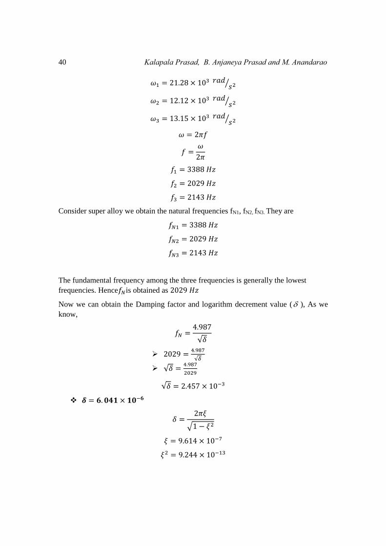
40 Kalapala Prasad, B. Anjaneya Prasad and M. Anandarao
𝜔1 = 21.28 × 10³ 𝑟𝑎𝑑𝑠2⁄
𝜔2 = 12.12 × 10³ 𝑟𝑎𝑑𝑠2⁄
𝜔3 = 13.15 × 10³ 𝑟𝑎𝑑𝑠2⁄
𝜔 = 2𝜋𝑓
𝑓 =𝜔
2𝜋
𝑓1 = 3388 𝐻𝑧
𝑓2 = 2029 𝐻𝑧
𝑓3 = 2143 𝐻𝑧
Consider super alloy we obtain the natural frequencies fN1, fN2, fN3. They are
𝑓𝑁1 = 3388 𝐻𝑧
𝑓𝑁2 = 2029 𝐻𝑧
𝑓𝑁3 = 2143 𝐻𝑧
The fundamental frequency among the three frequencies is generally the lowest
frequencies. Hence𝑓𝑁is obtained as 2029 𝐻𝑧
Now we can obtain the Damping factor and logarithm decrement value ( ), As we
know,
𝑓𝑁 =4.987
√𝛿
2029 =4.987
√𝛿
√𝛿 =4.987
2029
√𝛿 = 2.457 × 10⁻³
𝜹 = 𝟔. 𝟎𝟒𝟏 × 𝟏𝟎−𝟔
𝛿 =2𝜋𝜉
√1 − 𝜉2
𝜉 = 9.614 × 10⁻⁷
𝜉2 = 9.244 × 10⁻¹³
Performance Evaluation for Super Alloy (Ni-Cr) Designed Structural Assembly 41
EXPERIMENTAL ANALYSIS WORK:
Graph-1
Graph-2
42 Kalapala Prasad, B. Anjaneya Prasad and M. Anandarao
Here δ − logarithmic decrement.
Xa and Xb are the peaks of two consecutive waves.
ζ – damping factor
from the above graph
Xa = 28.71m/s2
Xb = 28.82 m/s2
δ = log28.82
28.71 =0.00000346=3.46×10⁻⁶
3.46×10-6= 2π ζ
√1−ζ2
Damping factor ζ = 5.507×10⁻⁷
EXPERIMENTAL PROCEDURE USING FFT ANALYZER:
1. Arrange the cantilever by fixing blade at the end of FFT equipment.
2. Calculate the length of the fixture used for holding the blade of the turbine and
hence leave its mark on the blade assembly.
3. At the centre of the blade affix an accelerometer on the face of the bar opposite to
the face of the blade.
4. Fix the bar exactly into the lot of the fixture such that a cantilever will be formed.
5. Now connections of various wires , cables of vibration analysers ,pc or laptop,
accelerometer and the impact hammer are done with the aid of manuals or under the
guidance of experts.
6. Switch on the AC power supply.
7. Run vibration analysis and experimental modal analysis software that are
previously installed in pc/laptop. Provide necessary inputs and correspondingly check
the settings in the software
8. Always ensure for proper power supply and check for the communications between
the devices that are connected
9. The four channel analyser used here is a DEWE software. Adjust the x and y axis
before starting the experiment.
10. Acceleration is taken on x-axis while frequency is considered to be on Y-axis.
11. Now with the help of a impact hammer, provide impacts at the tip of specimen on
the cantilever, one by one.
Performance Evaluation for Super Alloy (Ni-Cr) Designed Structural Assembly 43
12. Vibration analyser receives the corresponding signals from the impact hammer
and accelerometer, which it compares and analyses using the software.
13. We can obtain the natural frequencies of the cantilever from the frequency
function response curve .Read the curves corresponding to the peaks of these curves.
14. The obtained graphs will demonstrate the first natural frequency.
15. The damping factor can be obtained from the logarithmic decrement formula.
RESULTS AND DISCUSSION
Performance evaluation of Super alloy designed gas turbine.
1. A prototype physical model gas turbine made of Super alloy has been
examined experimentally.
2. In their experiment it is found that it is effective in its functioning on the basis
of output/results.
3. The theoretical and experimental values are compared and analyzed in this
output and results of the functioning of aluminium alloy gas turbine.
4. In the comparative analysis of both the theoretical values and experimental
values of natural frequency damping factor logarithmic decrement are
examined.
5. The range between theoretical values and experimental values have been
calculated and it is found that the values of range between them is within the
permitted levels the range between theoretical values and experimental value
of natural frequency damping factor logarithmic decrement are calculated and
got the error values.
I. In the case of natural frequency the error value it was found 4.066%.
II. In the case of damping factor the error value between theoretical and
experimental values is found if 10.79.
III. In the case of the logarithmic decrement between the theoretical and
experimental values is found at 8.11.
On the base of the above error values it shows that the performance of the gas turbine
is effective and getting the operational output on the expected lines.
44 Kalapala Prasad, B. Anjaneya Prasad and M. Anandarao
Table: 3
FACTORS AFFECTING THEORETICAL
VALUE
EXPERIMENTAL
VALUE RANGE % ERROR
Natural frequency( n ) 2029 2115 86 4.066
Damping factor (ζ) 9.91X10⁻⁷ 8.84 X 10⁻⁷ 1.07X10⁻⁷ 10.79
Logarithmic decrement
value( ) 6.04X10⁻⁶ 5.55 X 10⁻⁶ 0.49X10⁻⁶ 8.11
CONCLUSIONS:
From the above study of performance evaluation of super alloy designed gas turbine it
is observed that all the critical parameters namely blade(Nickel Chromium), disc
(nickel Chromium), rotor(mild steel), performance is critically examined and
investigated on the different operational parameters using the component mode
synthesis.
ACKNOWLEDGMENT
I am very much thankful Professor B.Anjaneya Prasad Garu and Co Guide
M.Ananda Rao Sir giving a valuable suggestions to write up in this paper.
REFERENCES:
[1] B.K.Chai and B.S.Yang 2001 “Multi objective optimum design of rotor
bearing systems with dynamic constraints using immune algorithm” Journal of
engineering for gas turbines and power, Vol.123 P.P.78-31.
[2] M.A.Rao, K.V.J Rao, Ch.Penchalaiah, J.Srinivas and srinivas kolla2002 “
Optimum design of axial flow gas turbine stage using genetic algorithm
approach J.Engg. for gas turbines and power.
[3] Dr.S.Vijayarangam, V.Alagappam and I.Rajendran 1999, Design optimixation
of leaf springs using genetic algorithms” I.E(1) Jornal-m Vol.79 P.P 135-179.
[4] H.W.oh and K.Y.Kim 2011 “ Conceptual design optimization of mixed flow
pump impellers using mean stream line analysis” Proc. Instn.Med. Engrs
Vol.215, part A P.P 133-138.
[5] SSRao and R.S.Gupta 1980 “Optimum design of axial flow gas turbine stage,
Part II solution of the optimization problem and Numerical results” Journal of
Engg for power Vol.102, P.P 790-797.
[6] O.E. Balje and R.L. Binsley 1968 “Axial Trubin performance evaluation part-
B-Optimixation with and without constraints” Journal of Engg for power
Performance Evaluation for Super Alloy (Ni-Cr) Designed Structural Assembly 45
P.P.349-330.
[7] Xiang-Jin-Wu, Guu-Jun-Xian, Zhomg-xio-Go 2001 “An overview of rotor
blades optimum design for helicopter vibration reduction” Journal of Beijing
university of Aeronautics Vol 27 No.1 P.P.32-5.
[8] M.V.Petrovic, G.S.Dulikravich and T.J Martin 2001 “optimization of
multistage turbines using a through flow code” Proc.Instn.Mech.Engrs
Vol,.215 Part-A, P P 559-569.
[9] William Carnegie 1959 “Vibrations of pretwisted Cantilever blading” Journal
of Engg for industry. Vol 173, No.12, P.P 343-36.
[10] M.A,Rao and J.srinivas 2000 “Torsional vibrations of pretwisted blades using
artificial neural networks technology” Engineers with computers 16p: 10-15.
[11] T.H.Young and T.M.Lin 998 “Stability of rotating pretwisted tapered beams
with randomly varying speeds” Journal of vibration and Accoustics, vol.120.
P.P 784-4790.
[12] M.H.Liu and G.T.Zheng 2008 “Improved component mode synthesis for
nonclassically Damped Systems” AIAA journal, Vol46 No.5.
[13] Klaus- Jurgen Bathe and Jian Dong 2014 “Component Mode Synthesis with
subspace iterations for controlled accuracy of frequency and mode shape
solutions” Computer and structures Vol.139 Pg 28-32.
46 Kalapala Prasad, B. Anjaneya Prasad and M. Anandarao