The LoRaWAN communication protocol can be used for the implementation of the IoT (Internet of Things) concept. Currently,most of the information regarding the scalability of the LoRa technology is commercial and deals with the best-case scenario.Thus, we need realistic models, enabling the proper assessment of the performance level. Most of the time, the IoT concept entailsa large number of nodes distributed over a wide geographical area, therefore forming a high density, large-scale architecture. Itis important to determine the number of collisions so that we can assess the network performance. The present paper aims atassessing the performance level of the LoRaWAN technology by analyzing the number of packet collisions that can occur. Thus,this paper determines the maximum number of LoRa nodes that can communicate with a Gateway considering the LoRaWANprotocol specifications. Furthermore, we have proposed a series of solutions for reducing the number of collisions and increasingthe capacity of the communication channel.
1. Introduction
New technologies have emerged lately, such as LoRa (LongRange) [1], Sigfox [2], and Weightless [3], enabling efficientlong distances wireless communication. Wireless SensorNetworks (WSN) have the potential to improve our lives. Inrecent years we have witnessed a fusion between WSN topicand the Internet ofThings (IoT) concept.These emerging newtechnologies have the ability to increase the quality of life.TheIoT concept refers to the interconnection of different devicesand nodes to Internet. The concept entails the integrationof sensors that often have low processing power and limitedcommunication capabilities are most of the time batterypowered.
LTE (Long-Term Evolution) mobile networks use a cen-tralizedmanagement system, by implementing a star networktopology. An LTE base station can typically handle a fewthousands of devices, so the existing mobile infrastructure isnot ready to integrate tens of thousands of devices, providingsupport for future IoT applications.
Thus, it is imperative to develop, analyze, and implementnew technologies as to increase performance by maximizing
scalability, all by enhancing M2M (Machine-to-Machine)communications. LPWA (Low-Power Wide Area) technolo-gies are most often used in M2M communications. Thesenetworks virtually are an interface between the industrialenvironment and the central server area where data iscollected, processed, and stored.
The main features of LPWA nodes are operation inunlicensed ISM frequency bands, extended battery life in theorder of decades, and low data transfer rates all in a low costwireless module. Also, the nodes must be able to sense andinteract with the environment. The technology performanceusually depends on the channel access technique, the dutycycle regulations, and other parameters like modulationmechanism and spectrum allocation.
These LPWA technologies must obtain a reliable datatransfer over tens of kilometers, by using a high communica-tion link budget while achieving a receiver's sensitivity of -125dBm, thus having the ability to decode highly attenuated sig-nals. The communication range is increased on the expanseof a low data rate. The used modulation mechanisms can bedivided into narrowband and broadband techniques.
HindawiWireless Communications and Mobile ComputingVolume 2018, Article ID 6730719, 9 pageshttps://doi.org/10.1155/2018/6730719
These technologies are generally used to form stars-of-stars network topologies. This eliminates the need ofdeveloping and implementing certain complicated multihoptechnologies, each node being able to communicate directlywith the sink node (theGateway node).TheLoRaWAN (LongRange Wide Area Network) communication protocol is auseful candidate for implementing the IoT concept.The LoRamodulation is located at the physical level of the LoRaWANcommunication protocol. This modulation is patented bySemtech.
The paper is structured as follows: the short introductionwithin Section 1 is followed by a short presentation of theLoRa technology. Section 3 presents the ADR (Adaptive DataRate) mechanism defined within the LoRaWAN protocol.The channel access techniques and a short state-of-the-artreview in order to highlight the need to implement a study forassessing the scalability of the LoRa technology are addressedin Sections 4 and 5. Section 6 outlines and discusses theexperimental results by analyzing the number of collisionsproduced on the communication channel. The Conclusionsends this paper.
The main contribution of this work is to perform a studymainly aimed at assessing the performance level associatedwith the LoRaWAN communication protocol. Therefore,we analyze the number of collisions and the throughputparameter, by studying the impact of the parameters: thespreading factor, the duty cycle, and the channel bandwidth.
2. LoRa Technology
The LoRa modulation is located at the physical level of theLoRaWAN communication protocol. This modulation oper-ates in the sub-GHz ISM (Industrial, Scientific, and Medical)band using a proprietary spectrum spreading technique. Themodulation provides bidirectional communication througha special CSS (Chirp Spread Spectrum) spread spectrummechanism that spreads the narrow band signal over a largerfrequency band. The resulting modulated signal is highlyresistant to noise and interferences.
The transmitter modifies the chirp signal frequency overtime without changing the phase of the signal between twoadjacent symbols. As long as the modulation frequency isslow enough so as to putmore energy on the chirp symbol, thereceivers located at very large distances can decode a severelyattenuated signal.
The LoRaWAN specifications define three types of nodes:classes A, B, and C. A class A device sends messages to theGateway module during certain periods of time, dependingon the specifics of an application. Then, the LoRa nodeopens a reception slot to allow the Gateway to send ACK(acknowledgement) messages or other type of commands.TheGateway node receives themessages from the LoRa nodeand sends them to the Network Server.
Class B extends class A by adding scheduled messagereception slots; class C prolongs class A, always keeping thereceiving time slot open, except when information is sent.Typically, a class A or class B device is powered by a battery;meanwhile a C type node is powered by the electrical networkdue to high energy consumption.
Table 1: LoRa parameters.
Parameters ValuesSpreading Factor (SF) 6 to 12Channel Bandwidth (BW) 125 kHz, 250 kHz, 500 kHzPower -1 to 14 dBm
LoRa communication supports multiple spread factors(SF) (between 6 and 12) to achieve the compromise betweenthe communication range and the data transfer rate. It alsouses a Forward Error Correction (FEC) technique that,along with LoRa modulation, increases the sensitivity ofthe receiver. Table 1 lists the main parameters of the LoRacommunication protocol, such as spreading factor, channelbandwidth, and the transmitted power.
LoRaWAN is the communication protocol that uses theLoRa modulation at the physical level. Figure 1 presentsthe architecture of the LoRa communication system thatincludes the end-device modules and the Gateway modulesthat retransmit messages to the Network Server within theLoRa architecture. The user is interacting with the system atthe level of the application.
The data transfer rate varies from 300 bps to 37.5 kbps,depending on the spreading factor and the bandwidth of thecommunication channel. A LoRa Gateway has the ability tosimultaneously receive and broadcast messages with differentSF (spreading factors). The LoRa specific architecture iscomposed of endnodes andGatewaymodules that retransmitmessages from the terminal nodes to the Network Server.
Messages sent by LoRa end devices are received byall Gateway devices, so a star-of-stars network topologyis created. The implementation of this degree of diversityincreases the likelihood that a message will be receivedsuccessfully, contributing to the possibility of deployinglocalization services. The implementation of a localizationservice involves using a Time Difference of Arrival (TDOA)technique, which entails the use of Gateway synchronizationtechniques.
The LoRa specification allows devices and Gateways tobe able to transmit at any time. There is no channel verifi-cation procedure or CSMA (Carrier Sense Multiple Access)algorithm implemented to avoid collisions. The LoRaWANprotocol uses an ALOHA type communication mechanism,where the packet length is variable. According to LoRaprotocol specifications, nodes can transmit on any availablechannel at any time using any available data rate, as longas a number of rules are complied with. The node selectsthe channel in a pseudorandommode for each transmission.The frequency shifting offers the main advantage of theLoRa communication which is resistance to interferences.The LoRa node respects the duty cycle parameter and otherregulations assigned to the regions in which it operates.
The LoRa communication, for the Europe zone andthe 868 ISM frequency band, has a regulated duty cycleparameter ranging from 0,1% to 1%. The parameter dependsof the subband allocation and the geographical region of theimplemented network. In a previous paper, published by theauthors of [4], the duty cycle restriction and the ToA (Time
Wireless Communications and Mobile Computing 3
LoRaGateway
Internet
LoRaGateway
EthernetLoRa
NetworkServer
Application Server
SF=12
EthernetLoRa modulation
SF=12
SF=7
SF=8
SF=7
SF=9
SF=7
Figure 1: LoRaWAN communication system.
SF=8SF=10SF =12
0
200
400
600
800
1000
1200
1400
TIM
E O
N A
IR [m
s]
20 30 40 50 60 7010PAYLOAD [bytes]
Figure 2: Time on air parameter for different SF and packetpayloads.
on Air) influence are analyzed in detail. If the duty cycleparameter is limited to 0,1% the LoRa node can communicateonly 3,6 seconds per hour assuming that no other restrictionsexist in place.
Figure 2 presents the ToA parameter for different SF andpacket payloads.We can observe that if the SF is increased theToA parameter is significantly higher.The frequency channelbandwidth for the obtained results is 250 kHz. For example,if the packet payload is 40 bytes for a SF=8 we obtain a ToA of60ms and if SF=12 the obtained ToA is approximately 872ms.One strategy to increase the transmitting time of a LoRa nodeis to switch between the subbands of the allocated channel.
If the SF parameter is increased the communication rangeis increased; meanwhile the data rate is decreased.This aspectdetermines a high ToA parameter. So, the LoRa technologyoffers a compromise between data rate and communicationrange.
3. LoRaWAN Data Rate
The LoRa nodes have the possibility of setting the data rate,according to regional regulations. The data rate settings arenumbered from 0 to 6 and represent a predefined set ofsettings, such as the spreading factor and the coding rate.A certain data rate can be selected with the help of somecommands at the MAC level. The specification recommendsthe implementation of a certain data rate control algorithm.The algorithm is controlled by the Network Server that cansend commands to theMACnodes to increase or decrease thedata rate, depending on the level of the received signal.Whenan ACK acknowledgementmechanism is implemented, if thenode does not receive the first two consecutive acknowledge-ments, it automatically performs a downgrade of the data rate.
Table 2 presents the data rates defined by the LoRaWANspecifications. The LoRaWAN specification defines a mech-anism for adapting the Adaptive Data Rate (ADR) transferrate without giving any details regarding the monitoredparameters or those involved in the rate selection process.
The Things Network (TTN) [5] is a data aggregationservice provider that allows the creation of a IoT network. Inthis case, the Gatewaymodule will transmit the collected datato the TTN network; meanwhile, the user views and interactswith the data, by using a web interface. The infrastructuredefined by TTN uses a modified version of the ADR algo-rithm that can be applied only to static nodes.The decision ofusing themechanism can be taken at a node level thatmay opt
for this feature. From the moment a node decides to use theADR algorithm, the network will collect the SNR parameterand the number of Gateways that have received that signalfor the last 20 packets. This information is processed in orderto calculate how much margin is used to increase or to lowerthe data rate by setting a lower transmission power level [6].Therefore, the decision to change the data rate is taken.
Papers [7–10] analyze and evaluate various aspects ofthe LoRa technology, starting from the modelling of thecommunication channel to the development of some IoTapplications. However, none of these works performs ananalysis of the communication channel capacity by takinginto consideration various configurations. In previous paperspublished by the authors of [4, 11, 12] the different challengesand problems of the LoRaWAN communication were ana-lyzed and discussed. The main contribution of the presentpaper is the analysis and evaluation of the access mechanismto the communication channel. After analyzing the obtainedresults, we propose a series of actions and solution aimed atincreasing the performance level by reducing the number ofcollisions within the communication channel.
4. Channel Access Technique
A LoRaWAN network entails the use of different commu-nication channels that are configured and monitored byGateway devices. The number of allocated channels dependson regional restrictions or other configurations specific tothe wireless network.Therefore, there are channels dedicatedto data transmission (called main channels) and a channeldedicated to the Gateway responses for the LoRa nodes(downlink channel), and finally we have channels used by theLoRa nodes for sending the requests to a Gateway module(uplink channels).
When a LoRanode sends a packet, it selects randomly oneof the channels and transmits, without previous performingof a carrier sense type verification and without the useof a preset synchronization time slot. This mechanism ofaccess is a specific ALOHA type access, with the mentionthat the length of the packet is variable. After performinga transmission, the LoRa node opens the receiver for twoshort receiving slots: the first slot corresponds to the uplinkchannel, while the second one corresponds to the downlinkchannel.
LoRaWAN defines ten communication channels forEurope zone. From these, 8 channels have multiple data
channels varying from 250 bps to 5,5 kbps. There are twohigh speed channels providing a transfer rate of 11 kbps and50 kbps, respectively, using an FSK (Frequency-Shift Keying)modulation. The maximum permissible transmission poweris of +14 dBm for the EU area. The wireless communicationlink budget is up to 155 dB.
The SF (spreading factor) parameter occurring during theLoRa modulation is basically the ratio between the symbolrate and chip rate.Theuse of a high SF determined an increaseof the Signal to Noise Ratio (SNR) parameter, enhancingthe receiver sensibility, but generating as a side effect theincreases the airtime of the packet. The coding of a symbol isperformed by using 2SF chips.Thus, if a SF of 12 is used, 4096chips/symbol are used. The SF parameters can take valuesfrom 6 to 12.
Figure 3 presents the LoRa communication channels forthe ISM 868 MHz frequency band for the EU area. The bandis defined from 863 to 870 MHz. It can be seen that the 8channels are separated by 0.3 MHz, except channel 17, a highdata rate channel.
Figure 4 shows the reception slots defined at the level ofthe LoRaWAN protocol; the time intervals are arranged atdifferent time slot intervals from the time moment at whichthe LoRa node transmits the information.
Wireless Communications and Mobile Computing 5
The first reception slot is opened T1seconds after the
completion of the uplink transmission, while the secondslot is opened one second later. The uplink channel isused for the first slot, while the downlink channel is usedfor the second slot. The reason for using this communi-cation mechanism is to reduce the energy consumptionassociated with the communication procedure. The LoRanode does not open the second communication slot whenit receives a frame within the first slot. It is also possi-ble to send an ACK reception acknowledgement that canbe required by both the Gateway module and the LoRanode.
The LoRa specification does not specify the length ofthe reception slot; however, it should be large enough toenable the receiver to efficiently detect the permeabilityof the LoRa packet needed for synchronization. The valueT1is configurable and implicitly equal to the second time
period.According to the LoRaWAN specifications defined by the
LoRa Alliance, a Gatewaymodule can transmit data to a classA node only within a receiving slot which can be initiatedonly after the LoRa node sends a packet. This reduces theenergy consumption of the LoRa node without sparing theGateway module which is not battery powered. Therefore,class A cannot guarantee a certain maximum delay for thedownlinkmessages, so class B or C should be used in the caseof delay-sensitive applications.
If the node does not receive an ACK message, it retrans-mits the same message. This retransmission is performedon a randomly selected channel after a time period longeror equal to ACK TIMEOUT seconds; the parameter israndomly selected between 1 and 3 seconds. At the sametime, the retransmission is performed at a much lowertransfer rate. The maximum number of retransmissions isset to 8, after which the packet is eliminated, and the MAC(Medium Access Control) level will notify the applicationlevel of the failed transmission. If the LoRa node wantsto transmit an empty frame, it still needs to include apayload of 13 bytes because of the overhead. For the ISM863-870 MHz frequency band, the timeframe associatedwith an ACK is almost 1 second (while the maximumlength of a frame needs a time frame of 2.4 seconds)[1].
5. Related Work
Mikhaylov et al. [13] analyzed and assessed the through-put of the LoRa technology, determining the airtime ofa packet. Therefore, it is possible to estimate the max-imum number of nodes that can communicate with aGateway module. The purpose of this paper was to ana-lyze the ALOHA communication mechanism. The resultsare obtained at an empirical level. A mathematical modelof the access mechanism to the communication channelis presented in [14]. A certain threshold of the networkload is also calculated in this paper by estimating thethroughput. When this threshold value is reached, the PER(Packet Error Rate) parameter increases rapidly towards
1, because the packet relaying causes an avalanche effectleading to the saturation of the communication chan-nel.
Bor et al. [15] analyzed the access mechanism of thecommunication channel. From the obtained results, it can beseen that when the same SF (spreading factor) is used, by boththe receiver and the transmitter, the packets are received evenif a third node attempts to interfere with the transmission.Thus, the separation of channels by using different SF proveseffective. One or two simultaneous transmissions can bereceived with high probability, if there is a separation of atleast 3 symbol periods between them.The paper also analyzesthe possibility of implementing a carrier activity detectionmechanism. An algorithm for the automatic selection ofcommunication parameters is presented in [16] so as toachieve a performance level as high as possible, at the sametime ensuring energy efficiency.
Blenn N. et al. [17] obtained a series of experimentaland empirical results by analyzing the influence of thepayload on the quality of the received signal.The experimentshave been conducted over an 8-month period, with theresults showing that the LoRa channel occupancy rate is notevenly distributed, a fact that contributes to a decrease inperformance. This phenomenon is based on the fact that themajority of LoRa nodes use the default settings programmedby the manufacturer, a fact that causes the overload ofcertain channels. The purpose of the paper was to use certainuser-defined communication channels according to the RF(Radiofrequency) environment congestion.
In [18], the Doppler effect over the LoRa modulation isanalyzed, by performing a series of experimental measure-ments. From the obtained results, the authors conclude that,by using SF=12, a communication range of up to 30 km witha packet loss of 62 % can be obtained. In [19] the mathematicmodel of the LoRa modulation and also of the demodulationprocess based on signal processing theory is presented. Thepaper also presents a comparison of the performance levelsbetween the LoRa modulation and the FSK (Frequency-ShiftKeying) modulation, regarding the value of the encoded biterror rate parameter. The obtained results show that when anAWGN (AdditiveWhite Gaussian Noise) channel is used, theLoRa modulation ensures a higher performance level.
Liao et al. [20] analyze the effect of the simultaneousLoRa transmissions over the performance level. The paperproposes the integration of a CT (Concurrent Transmission)type flooding into the technology. CT is an extremely efficientflooding type protocol that has recently revolutionized thedesign of the multihop networks based on the IEEE-802.15.4standard. Instead of attempting to avoid packet collision, CTenables more nodes to send packets with the same contentsimultaneously, at the same time moment. By allowing suchsynchronized packets collisions, CT enables rapid back-to-back relaying of packets that considerably improve theefficiency of the network.The paper proposes the implemen-tation of such a strategy for increasing the performance levelof the LoRa networks by introducing a multihopmechanism.None of the papers evaluate the maximum number of nodesthat can communicate on a channel, taking into considerationa real implementation scenario.
6 Wireless Communications and Mobile Computing
6. Simulations Results
TheLoraSim [21] simulator has been adapted andmodified tocomply with the designed scenarios. The simulator is basedon a mathematical model [22] of LoRa communications,capable of monitoring the resulting number of collisions[23]. Also, the LoRa receivers’ sensitivity values presented inTable 3 have been integrated in the mathematical model.
Currently, most of the information regarding the scalabil-ity of the LoRa technology is commercial and deals with thebest-case scenario. Thus, we need realistic models, enablingthe proper assessment of the performance level. Table 4 showsthe simulation parameter used in the simulation model. Itcan be seen that there have been three cases implemented,A, B, and C. The parameters used in the simulations are thespreading factor, the channel bandwidth, and the coding rate.
Figure 5 shows the total number of LoRa packets sent.Theduty cycle parameter is 1%. For 100 nodeswe have transmittedapproximately 10.000 packets. In this case the SF parameter is12, the channel bandwidth is 125 kHz, and the code rate is 4/8.Considering our simulation scenario and proposed model, anodemust comply with the duty cycle restriction of 1%.Thus,in a 24-hour interval a node will transmit one packet every14,4 minutes. In conclusion a node will send approximately 11packets per day.
Figure 6 shows the number of collisions produced whenthe parameters in Table 4 have been used. The collisionsparameter (Packet Collisions Rate) is displayed in percent-ages and represents the number of collided packets withregard to the total number of sent packets. We use thisapproach in order to estimate the maximum number of LoRanodes that can communicate on a single communicationchannel. Thus, the 0% value represents the fact that nocollision has been recorded; if the registered value is 100%,none of the packets has been received properly. In orderto obtain a high performance level, it is necessary that thenumber of collisions be under 5% of the total number oftransmitted packets.
The analyzed collisions parameter does not capture theperformance of the individual node but represents a globalmetric analyzed across the entire network architecture. Thecollision parameter is evaluated when the total number of thenetwork nodes has increased from 100 to 1000 and to 4.500nodes, respectively.
The size of the LoRa packet used within the simulation isabout 20 bytes. The simulated time frame has been about 24hours. Each node sends packets towards the Gatewaymoduleevery 14.4 minutes so as to comply with the LoRaWANspecification duty cycle restrictions. The A configuration ismost often used in practice, because it ensures the largestcommunication radius. The simulated B configuration cor-responds to the fastest transfer rate; this is the reason whywe can also observe the lowest error rate; since the airtime ofthe packet is the lowest, 7.07 ms, the probability of a collisionoccurring is low. It can be noticed that for the C configurationthe airtime is 1.712 s; therefore, the number of collisions ismuch higher compared to the B configuration. Thus, thenumber of collisions for 100 nodes is 26.6 % for configurationA, 9.73% for configuration B, and 31 % for configuration C.
0
2000
4000
6000
8000
10000
12000
NU
MBE
R O
F PA
CKET
S
20 30 40 50 60 70 80 90 10010NUMBER OF NODES
Figure 5: Number of packets transmitted for a duty cycle of 1%.
Collisions CASE ACollisions CASE BCollisions CASE C
20 30 40 50 60 70 80 90 10010NUMBER OF NODES
05
101520253035
COLL
ISIO
NS
[%]
Figure 6: Collisions parameter for different simulation scenarios.
Figure 7 presents the collisions parameter when the num-ber of nodes varies from 100 to 1000. The maximum channelcapacity is reached when 95% of the transmitted packets areaffected by the collision. From the obtained results, we canconclude that the maximum number of nodes which cancommunicate on a LoRa channel is approximately 875 nodesfor configuration A and 1000 nodes for configuration C. Theduty cycle used in this particular scenario is 1%.
Figure 8 presents the collision parameter when the dutycycle parameter is reduced from 1% to 0.5%. The obtainedresults show that the number of collisions is significantlylower when the duty cycle parameter is reduced.The numberof collisions decreases by approximately 40%, thus increasingthe capacity of the LoRa communication channel.
Figure 9 represents the collisions parameter when thenodes number increases from 500 to 4500. The obtainedresults show that the maximum number of nodes that cancommunicate on a channel is approximately 4000, when theduty cycle parameter is of 0,5%. The parameters used areSF=12, BW=125, and CR=4/8.
From the obtained results, we can see that the doubling inthe number of nodes from 500 to 1000 determines an increaseof the collisions parameter by 20,7%.
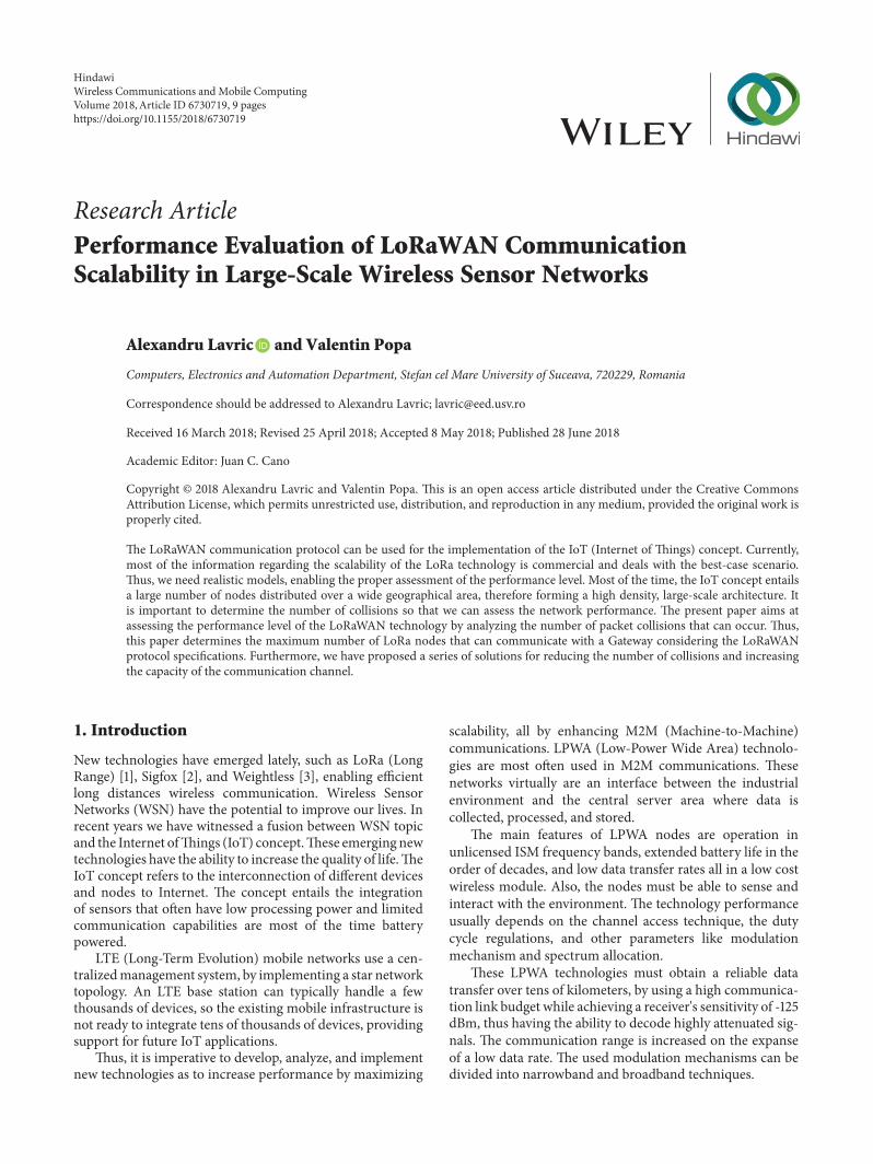
Figure 10 shows the number of packets sent when thenumber of nodes is varied from 1000 to 7000 and the dutycycle parameter is 0,1% and 0,5%. From the obtained results,we can observe that if the duty cycle parameter is 0,5%, weobtain a total number of sent packets of 40.000. Because of thecollision phenomenon, not all the packets will be received.
Figure 7: Collisions parameter for A and C configurations.
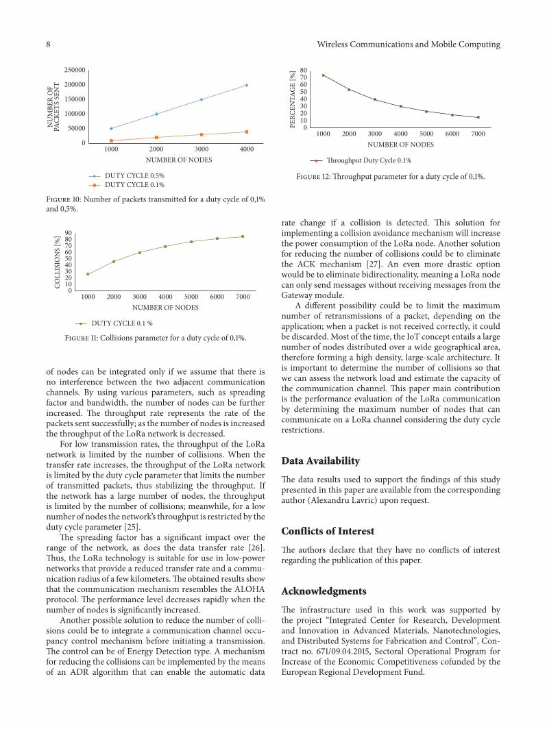
Figure 11 shows the collisions parameter when theduty cycle parameter is reduced from 0,5% to 0,1%. Thisphenomenon generates an increase of the communicationchannel capacity. In this configuration theoretical, a numberof almost 7000 nodes can be integrated in the communicationchannel in this case. From the obtained results, we can see thatthe collisions parameter level for 4000 nodes is almost 27%lower than in the previous case (e.g., a duty cycle of 0,5%).For a number of 1000 if the duty cycle parameter is 0,1%, thecollisions parameter is almost 26,4%. This means that fromthe total number of packets sent, only 26,4% are affected bycollisions.
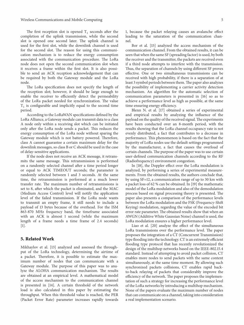
Figure 12 shows the throughput of the network when thenumber of nodes is varied from 1000 to 7000 and the dutycycle parameter is 0,1%. The throughput rate represents therate of the packets sent successfully; as the number of nodesis increased, the throughput of the LoRa network is decreasedbecause the number of collisions is increased.
7. Conclusions
The purpose of this paper is to analyze the performance levelof the LoRaWAN technology, by focusing on the maximumnumber of nodes that can communicate on a LoRa commu-nication channel and thus by evaluating the scalability of thetechnology in a large-scale WSN.
Collisions CASE C DUTY CYCLE 1%Collisions CASE C DUTY CYCLE 0.5%
05
101520253035
COLL
ISIO
NS
[%]
20 30 40 50 60 70 80 90 10010NUMBER OF NODES
Figure 8: Collisions parameter versus duty cycle.
Collisions Case C
0102030405060708090
100
COLL
ISIO
NS
[%]
1000 1500 2000 2500 3000 3500 4000 4500500NUMBER OF NODES
Figure 9: Collisions parameter for a duty cycle of 0,5%.
From the obtained results, we can conclude that theconfigurationwith the lowest transfer rate ensures the highestlevel of collisions. Because the airtime of the packet is ofa few seconds, it is prone to collisions that can negativelyinfluence the capacity of the communication channel. Theconfiguration with the lowest transfer rate is the most usedone, because it ensures the largest communication rangeby using a high spreading factor (e.g., SF=12). Thus, acompromise is reached between reducing the transfer rateand increasing the communication range. A possible solutionfor decreasing the number of collisions would be to increasethe transfer rate or decrease the duty cycle parameter atapplication level. The maximum number of nodes that canuse the same LoRa channel, so that we can obtain a high levelof performance, is almost 1000 nodes.
The Gateway module can receive data simultaneously onall 8 communication channels. From the obtained results,we can conclude that a number of approximately 8000nodes can simultaneously communicate with the Gatewaymodule when the duty cycle parameter is 1%. This number
8 Wireless Communications and Mobile Computing
DUTY CYCLE 0.5%DUTY CYCLE 0.1%
2000 3000 40001000NUMBER OF NODES
0
50000
100000
150000
200000
250000
PACK
ETS
SEN
TN
UM
BER
OF
Figure 10: Number of packets transmitted for a duty cycle of 0,1%and 0,5%.
DUTY CYCLE 0.1 %
0102030405060708090
COLL
ISIO
NS
[%]
2000 3000 4000 5000 6000 70001000NUMBER OF NODES
Figure 11: Collisions parameter for a duty cycle of 0,1%.
of nodes can be integrated only if we assume that there isno interference between the two adjacent communicationchannels. By using various parameters, such as spreadingfactor and bandwidth, the number of nodes can be furtherincreased. The throughput rate represents the rate of thepackets sent successfully; as the number of nodes is increasedthe throughput of the LoRa network is decreased.
For low transmission rates, the throughput of the LoRanetwork is limited by the number of collisions. When thetransfer rate increases, the throughput of the LoRa networkis limited by the duty cycle parameter that limits the numberof transmitted packets, thus stabilizing the throughput. Ifthe network has a large number of nodes, the throughputis limited by the number of collisions; meanwhile, for a lownumber of nodes the network’s throughput is restricted by theduty cycle parameter [25].
The spreading factor has a significant impact over therange of the network, as does the data transfer rate [26].Thus, the LoRa technology is suitable for use in low-powernetworks that provide a reduced transfer rate and a commu-nication radius of a few kilometers.The obtained results showthat the communication mechanism resembles the ALOHAprotocol. The performance level decreases rapidly when thenumber of nodes is significantly increased.
Another possible solution to reduce the number of colli-sions could be to integrate a communication channel occu-pancy control mechanism before initiating a transmission.The control can be of Energy Detection type. A mechanismfor reducing the collisions can be implemented by the meansof an ADR algorithm that can enable the automatic data
6000
Throughput Duty Cycle 0.1%
01020304050607080
PERC
ENTA
GE
[%]
2000 3000 4000 5000 70001000NUMBER OF NODES
Figure 12: Throughput parameter for a duty cycle of 0,1%.
rate change if a collision is detected. This solution forimplementing a collision avoidance mechanism will increasethe power consumption of the LoRa node. Another solutionfor reducing the number of collisions could be to eliminatethe ACK mechanism [27]. An even more drastic optionwould be to eliminate bidirectionality, meaning a LoRa nodecan only send messages without receiving messages from theGateway module.
A different possibility could be to limit the maximumnumber of retransmissions of a packet, depending on theapplication; when a packet is not received correctly, it couldbe discarded. Most of the time, the IoT concept entails a largenumber of nodes distributed over a wide geographical area,therefore forming a high density, large-scale architecture. Itis important to determine the number of collisions so thatwe can assess the network load and estimate the capacity ofthe communication channel. This paper main contributionis the performance evaluation of the LoRa communicationby determining the maximum number of nodes that cancommunicate on a LoRa channel considering the duty cyclerestrictions.
Data Availability
The data results used to support the findings of this studypresented in this paper are available from the correspondingauthor (Alexandru Lavric) upon request.
Conflicts of Interest
The authors declare that they have no conflicts of interestregarding the publication of this paper.
Acknowledgments
The infrastructure used in this work was supported bythe project “Integrated Center for Research, Developmentand Innovation in Advanced Materials, Nanotechnologies,and Distributed Systems for Fabrication and Control”, Con-tract no. 671/09.04.2015, Sectoral Operational Program forIncrease of the Economic Competitiveness cofunded by theEuropean Regional Development Fund.
Wireless Communications and Mobile Computing 9
References
[1] LoRa, http://www.semtech.com/wireless-rf/lora.html.[2] SigFox, https://www.sigfox.com/en.[3] Weightless, http://www.weightless.org/.[4] A. Lavric and V. Popa, “Long range wide area networks study,”
in Proceedings of the 11-th IEEE International Conference onElectromechanical and Power Systems (SIELMEN ’17), pp. 435–438, 2017.
[5] “TheThings Network,” https://www.thethingsnetwork.org/.[6] “The Things Network ADR Mechanism,” https://www.the-
thingsnetwork.org/wiki/LoRaWAN/ADR.[7] D. Bankov, E. Khorov, and A. Lyakhov, “On the limits of
LoRaWAN Channel Access,” in Engineering and Telecommuni-cation, pp. 10–14, International Conference, 2016.
[8] P. Sethi and S. R. Sarangi, “Internet of things: architectures,protocols, and applications,” Journal of Electrical and ComputerEngineering, vol. 2017, Article ID 9324035, pp. 1–25, 2017.
[9] J. Haxhibeqiri, F. Van den Abeele, I. Moerman, and J. Hoebeke,“LoRa scalability: a simulation model based on interferencemeasurements,” Sensors, vol. 17, no. 6, article 1193, 2017.
[10] J. Kim and J. Song, “A Dual Key-Based Activation Schemefor Secure LoRaWAN,” Wireless Communications and MobileComputing, vol. 2017, pp. 1–12, 2017.
[11] A. Lavric andV. Popa, “LoRawide-area networks from an Inter-net ofThings perspective,” inProceedings of the 9th InternationalConference on Electronics, Computers and Artificial Intelligence(ECAI), pp. 1–4, 2017.
[12] A. Lavric and V. Popa, “Internet of things and LoRa low-power wide-area networks challenges,” in Proceedings of the9th International Conference on Electronics, Computers andArtificial Intelligence (ECAI), pp. 1–4, 2017.
[13] K. Mikhaylov, J. Petaejaejaervi, and T. Haenninen, “Analysisof capacity and scalability of the LoRa low power wide areanetwork technology,” in Proceedings of the 22th EuropeanWireless Conference, pp. 1–6, 2016.
[14] D. Bankov, E. Khorov, and A. Lyakhov, “Mathematical modelof LoRaWAN channel access,” in Proceedings of the 18th IEEEInternational Symposium on A World of Wireless, Mobile andMultimedia Networks, WoWMoM 2017, Macau, China, 2017.
[15] M. Bor and U. Roedig, “LoRa for the Internet of Things,” inProceedings of the International Conference on Embedded Wire-less Systems and Networks, pp. 361–366, Junction Publishing,Canada, 2017.
[16] M. Bor and U. Roedig, “LoRa transmission parameter selec-tion,” in Proceedings of the 3th International Conference onDistributed Computing in Sensor Systems (DCOSS ’17), pp. 5–7,Ottawa, Canada, 2017.
[17] N. Blenn and F. Kuipers, “LoRaWAN in the Wild: Mea-surements from The Things Network,” https://arxiv.org/abs/1706.03086.
[18] J. Petajajarvi, K. Mikhaylov, M. Pettissalo, J. Janhunen, andJ. Iinatti, “Performance of a low-power wide-area networkbased on lora technology: Doppler robustness, scalability, andcoverage,” International Journal of Distributed Sensor Networks,vol. 13, no. 3, 2017.
[19] L. Vangelista, “Frequency Shift Chirp Modulation: The LoRaModulation,” IEEE Signal Processing Letters, vol. 24, no. 12, pp.1818–1821, 2017.
[20] C.-H. Liao, G. Zhu, D. Kuwabara, M. Suzuki, and H.Morikawa,“Multi-Hop LoRa Networks Enabled by Concurrent Transmis-sion,” IEEE Access, vol. 5, pp. 21430–21446, 2017.
[22] M. C. Bor, U. Roedig, T. Voigt, and J. M. Alonso, “Do LoRaLow-Power Wide-Area Networks Scale?” in Proceedings of the19th ACM International Conference on Modeling, Analysis andSimulation of Wireless and Mobile Systems, pp. 59–67, Malta,Malta, 2016.
[23] V. Thiemo, M. Bor Utz, and R. Juan Alonso, “Mitigating Inter-network Interference in LoRa Networks,” in Proceedings of theIn Proceedings of the, pp. 323–328, 2017.
[25] B. Kim and K.-I. Hwang, “Cooperative downlink listening forlow-power long-range wide-area network,” Sustainability, vol.9, no. 4, article no. 627, 2017.
[26] F. Adelantado, X. Vilajosana, P. Tuset-Peiro, B. Martinez, J.Melia-Segui, and T. Watteyne, “Understanding the Limits ofLoRaWAN,” IEEE Communications Magazine, vol. 55, no. 9, pp.34–40, 2017.
[27] A. Pop, U. Raza, P. Kulkarni, and M. Sooriyabandara, “DoesBidirectional Traffic Do More Harm Than Good in LoRaWANBased LPWA Networks?” https://arxiv.org/abs/1704.04174.