16
© PAKTON Technologies Pty Ltd 2012 i Perimeter Patrol Interface Technical Manual Issue 1.06

© PAKTON Technologies Pty Ltd 2012 i
Perimeter Patrol Interface
Technical Manual
Issue 1.06
© PAKTON Technologies Pty Ltd 2012 ii
Contents
1 INTRODUCTION .......................................................................................................................................... 1
Scope and Purpose .................................................................................................................................... 1
Part Numbers ............................................................................................................................................ 1
Glossary ..................................................................................................................................................... 2
2 SPECIFICATIONS ......................................................................................................................................... 3
Notes for all Z-Series energisers ............................................................................................................... 4
2.1 DANGER ...................................................................................................................................... 4
3 INSTALLATION ............................................................................................................................................ 5
Return to Factory Defaults (Jumper J4) .................................................................................................... 5
LED Indications .......................................................................................................................................... 6
WAN Configuration ................................................................................................................................... 7
4 ENERGISER CONFIGURATION FOR USE WITH THE PAE212 ....................................................................... 9
Example system ........................................................................................................................................ 9
5 USING MULTIPLE PAE212 BOARDS .......................................................................................................... 10
6 PERIMETER PATROL CONFIGURATION .................................................................................................... 11
Automatically Detecting Connected Devices .......................................................................................... 11
Manually Adding Active Zones ................................................................................................................ 12
APPENDIX A: Version Tables ....................................................................................................................... 13
PCB’s (Including minor “schematic only” revisions) ............................................................................... 13

© PAKTON Technologies Pty Ltd 2012 1
1 INTRODUCTION The PAKTON Security Electric Fence Energisers and Peripheral Devices are designed and manufactured by PAKTON Technologies of Brisbane, Australia. This document is an OEM Manual for the Perimeter Patrol Interface used to control the Security Energisers remotely using Perimeter Patrol and an Ethernet connection This manual relates to: PCB version: 1v00 and higher Firmware version: 1.00 or higher Current Firmware: 1.00
Scope and Purpose
This document is intended for the training of engineering and technical personnel both
internally and for our OEM customers.
As a reference for the features and specifications per version, as such it will be kept up to date
and re-issued with each revision of the PCB or firmware. Please ask PAKTON for the latest
version.
Part Numbers
PCB assemblies for OEM customers have a PAE prefix; while complete Products in enclosures are have a
PTE prefix.

© PAKTON Technologies Pty Ltd 2012 2
Glossary
OEM – Original equipment manufacturer.
Zone – A high voltage fence output and return to provide perimeter security.
Bi-polar – A Bi-Polar fence is an all-live wire fence. A Bi-Polar Energiser has the ability to
pulse synchronised positive and negative pulses down alternate wires of the
same fence line.
Conventional – A Conventional electric fence is wired in such a way that alternate live and
earth wires are on the fence.
Feed Voltage – (Also Fence Feed) The Voltage connection from the Energiser to the start of
the fence zone.
Return Voltage – (Also Fence Return) The Voltage connection from the end of a fence zone to
the monitoring circuit of the Energiser.
On/Armed – The Energiser is transmitting high (or low) voltage pulses onto the fence. The
fence is secure.
Off/Disarmed – The fence zone is unsecure, but is safe to perform maintenance on.
Positive Voltage – The Positive fence voltage on a Bi-polar Fence.
Negative Voltage – The Negative fence voltage on a Bi-Polar Fence.
Low Power mode – The fence live wires operate at a much lower voltage, typically 500V peak.
This ensures detection together with public safety.

© PAKTON Technologies Pty Ltd 2012 3
2 SPECIFICATIONS Table 1 - Specifications Table
Specification Name Specification
Number of Energisers Controlled 14 PTE1013 or PTE1023 Energisers
Required Software Perimeter Patrol (Version 4.1 or newer)
Energiser Connection Keypad Bus (+12, 0V, DAT)
Ethernet Connection 10BaseT via RJ-45
Power Consumption from Keypad Bus 10mA
User Inputs None
Switched Outputs None
Recommended Operating Temperature -15°C to +50°C
Enclosure (Optional) IP4x ABS Plastic
Size – PCB only 90mm high, 60mm wide, 30mm deep
Size – Enclosure 120mm high, 72mm wide, 35mm deep
Weight – packed (PCB only) 80 grams
Weight – packed (with Enclosure) 120 grams

© PAKTON Technologies Pty Ltd 2012 4
Notes for all Z-Series energisers
2.1 DANGER
There are potentially lethal high voltages inside the Z Series Energisers.
The high voltage inside the Z Series Energisers may take a long time to
discharge. Wait at least 10 minutes after turning off before opening the case.
Before working on the high voltage wiring of an electric fence, it is
recommended that the energiser be disarmed and an intentional short circuit is
placed from the fence live wires to earth. This is a sensible precaution against
the energiser being turned on by others or malfunctioning while working on the
fence.
If an electric fence is part of a multiple energiser system and the distance
between two separate electric fences, each powered by separate energisers, is
less than 2.5 meters, the energisers must be configured to operate in group
mode.

© PAKTON Technologies Pty Ltd 2012 5
3 INSTALLATION
It is recommended that all installations are performed by qualified technicians
1. Read this section entirely first!
2. Configure the Security Energisers into Group Mode as Slaves even if only using 1 Energiser.
NOTE: The Energiser IDs MUST start from ID=2 as the PAE212 is already configured as the Master with an ID=1.
3. Wire the Keypad bus into the PAE212 (+12V, 0V, DAT) from an Energiser
4. Connect the Ethernet port of the PAE212 to the building Local Area Network (LAN)
5. Take a note of the Serial Number of the PAE212 as this is what Perimeter Patrol will use to identify the PAE212
Return to Factory Defaults (Jumper J4)
If for some reason the PAE212 is not being recognised by Perimeter Patrol, or it is not working as expected, it may be beneficial to return it to Factory Defaults. This is achieved by removing the black Jumper located at J4 and removing the Keypad Bus connector. When the Keypad Bus connection is returned, the LEDs D5 and D6 will light for ½ a second followed by D7 blinking once. The D7 blink shows the PAE212 loading the Factory Defaults. Replace the Jumper across both pins of J4.
Ethernet Port
Keypad Bus
J4

© PAKTON Technologies Pty Ltd 2012 6
LED Indications
Power – the Green LED (D4) will be ON when the PAE212 has power
Energiser Synch – the Red LED D7 should BLINK once every second to indicate Energiser Synchronisation
Energiser Data – the Red LED D5 will BLINK rapidly (one blink per Energiser connected) when the PAE212 is receiving data from the Energiser
LAN Connected – when the PAE212 is connected to the Local Area Network (LAN) through the Ethernet Port, the Green LED D8 will be ON
LAN Activity – information sent by the PAE212 to Perimeter Patrol will be indicated by the Green LED D9
LAN Connected
Power
Energiser Synch
Energiser Data LAN Activity
© PAKTON Technologies Pty Ltd 2012 7
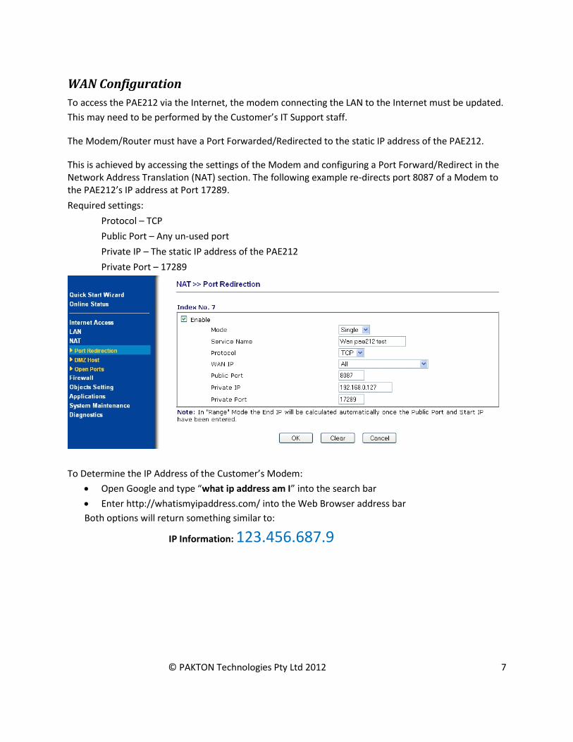
WAN Configuration
To access the PAE212 via the Internet, the modem connecting the LAN to the Internet must be updated.
This may need to be performed by the Customer’s IT Support staff.
The Modem/Router must have a Port Forwarded/Redirected to the static IP address of the PAE212.
This is achieved by accessing the settings of the Modem and configuring a Port Forward/Redirect in the Network Address Translation (NAT) section. The following example re-directs port 8087 of a Modem to the PAE212’s IP address at Port 17289.
Required settings:
Protocol – TCP
Public Port – Any un-used port
Private IP – The static IP address of the PAE212
Private Port – 17289
To Determine the IP Address of the Customer’s Modem:
Open Google and type “what ip address am I” into the search bar
Enter http://whatismyipaddress.com/ into the Web Browser address bar
Both options will return something similar to:
IP Information: 123.456.687.9

© PAKTON Technologies Pty Ltd 2012 8
Perimeter Patrol needs to be configured to access this IP address and Port number.
In the Add/Remove Zones section update the IP and Port for each Energiser connected to the PAE212.
NOTE: The Scan function will not work with a WAN connected PAE212. All Zones will have to be
Manually Added
For the above example enter 123.456.687.9 in the IP box and the Public Port number 8087.
Note: There is currently no security to prevent someone with another copy of Perimeter Patrol "stealing" control of the devices. This can only occur when your version of Perimeter Patrol is turned OFF, or not actively connected to the PAE212.
© PAKTON Technologies Pty Ltd 2012 9
4 ENERGISER CONFIGURATION FOR USE WITH THE PAE212
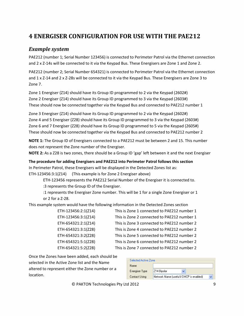
Example system
PAE212 (number 1; Serial Number 123456) is connected to Perimeter Patrol via the Ethernet connection
and 2 x Z-14s will be connected to it via the Keypad Bus. These Energisers are Zone 1 and Zone 2.
PAE212 (number 2; Serial Number 654321) is connected to Perimeter Patrol via the Ethernet connection
and 1 x Z-14 and 2 x Z-28s will be connected to it via the Keypad Bus. These Energisers are Zone 3 to
Zone 7.
Zone 1 Energiser (Z14) should have its Group ID programmed to 2 via the Keypad (2602#)
Zone 2 Energiser (Z14) should have its Group ID programmed to 3 via the Keypad (2603#)
These should now be connected together via the Keypad Bus and connected to PAE212 number 1
Zone 3 Energiser (Z14) should have its Group ID programmed to 2 via the Keypad (2602#)
Zone 4 and 5 Energiser (Z28) should have its Group ID programmed to 3 via the Keypad (2603#)
Zone 6 and 7 Energiser (Z28) should have its Group ID programmed to 5 via the Keypad (2605#)
These should now be connected together via the Keypad Bus and connected to PAE212 number 2
NOTE 1: The Group ID of Energisers connected to a PAE212 must be between 2 and 15. This number
does not represent the Zone number of the Energiser.
NOTE 2: As a Z28 is two zones, there should be a Group ID ‘gap’ left between it and the next Energiser
The procedure for adding Energisers and PAE212 into Perimeter Patrol follows this section
In Perimeter Patrol, these Energisers will be displayed in the Detected Zones list as:
ETH-123456:3:1(Z14) (This example is for Zone 2 Energiser above)
ETH-123456 represents the PAE212 Serial Number of the Energiser it is connected to.
:3 represents the Group ID of the Energiser.
:1 represents the Energiser Zone number. This will be 1 for a single Zone Energiser or 1
or 2 for a Z-28.
This example system would have the following information in the Detected Zones section
ETH-123456:2:1(Z14) This is Zone 1 connected to PAE212 number 1
ETH-123456:3:1(Z14) This is Zone 2 connected to PAE212 number 1
ETH-654321:2:1(Z14) This is Zone 3 connected to PAE212 number 2
ETH-654321:3:1(Z28) This is Zone 4 connected to PAE212 number 2
ETH-654321:3:2(Z28) This is Zone 5 connected to PAE212 number 2
ETH-654321:5:1(Z28) This is Zone 6 connected to PAE212 number 2
ETH-654321:5:2(Z28) This is Zone 7 connected to PAE212 number 2
Once the Zones have been added, each should be
selected in the Active Zone list and the Name
altered to represent either the Zone number or a
location.

© PAKTON Technologies Pty Ltd 2012 10
5 USING MULTIPLE PAE212 BOARDS
The Local Area Network can be used to connect multiple PAE212 Ethernet Adapter Devices to JVA
Perimeter Patrol, giving JVA Perimeter Patrol the ability to monitor and command multiple groups of
Security Electric Fence devices.

© PAKTON Technologies Pty Ltd 2012 11
6 PERIMETER PATROL CONFIGURATION
1. In Perimeter Patrol open the System Configuration window (SetupSystem Configuration…)
2. In the Zones Tab, Select the Ethernet option
3. Press the button
Automatically Detecting Connected Devices
1. In the Add/Remove Zones window press the
button. This will detect all of the PAE212 devices connected to
the same network as Perimeter Patrol. These will be displayed
in the Detected Ethernet Devices box
2. Click on each Detected Ethernet Device in turn and assign New
Settings:
Enter a number in the Ethernet ID (1-128).
Each PAE212 MUST have a unique number as this is used
to synchronise the PAE212 via the Ethernet connection.
Disable DHCP (recommended)
Enter a new Static IP Address (one that is un-used)
Press the button
This will ensure that all Energisers will be synchronised and able to respond to Perimeter Patrol
Commands.
3. The Num Devices box at the bottom of the list indicates the number of Energisers the PAE212
has remembered. If this number does not match the number of Energisers connected, press the
button. This forces the PAE212 to re-
evaluate the Keypad bus similar to the *68# function of a
Keypad. Press the button again to update
the Detected Zones box.
4. In the Detected Zones box, select and Add the Energisers to
be monitored to the Active Zones box.
The Detected Zones follow this numbering: ETH-XXXXXX:Y:Z
Where ETH represents Ethernet Interface
XXXXX is the Serial number of the PAE212
Y is the Group Mode Number programmed into the
Energiser (26xx#) with values from 2 to 15
Scan
Commit Changes to Devices
Add/Remove Zones
Clear list of Known Devices
Scan

© PAKTON Technologies Pty Ltd 2012 12
Z is the Zone number of that Energiser. 1 for a Single
Zone Energiser, 1 or 2 for a Dual Zone Energiser
5. All Zones that are Added to the system will be displayed in the
Active Zones box.
6. Select each Active Zone in turn and update the Name and
Energiser Type to make it easier to distinguish the Energiser
location
7. Press the button. If this is not done, all of the
changes will be lost
8. Press the Close button
9. The Map window of Perimeter Patrol will now have all of the
Active Zone boxes in the top Left Corner of the Map
Manually Adding Active Zones
An Active Zone can be added to Perimeter Patrol before the PAE212 is connected to the LAN, or before
the Energiser is connected to the PAE212. This requires knowledge of the Energiser configuration and
the PAE212 Serial number.
1. Pressing the button in the Active Zones section will create a new Active Zone
entry
2. Select the newly created Zone and then update all of the Zone information
Enter a suitable Name for the Zone
Select the Energiser Type from the list of available Z-series Energisers and Monitors
Enter the Network Name into the box. This is ETH-XXXXXX, where XXXXXX is the Serial
Number on the PAE212. Eg PAE212 with Sn. 156876 = ETH-156876
Enter the Group ID of the Energiser into the Keypad Bus ID box
Enter the Zone (Channel) number. This will always be 1 except for a Z-28
Both Zones of a Z-28 need to be Added to the Active Zones box. The only difference between the
settings for these is the Zone (Channel), one will be Zone 1, the other will be Zone 2.
3. When the Energiser and PAE212 are connected to the LAN, the Zone will become active on the
Map page. Until this occurs, the Zone will display Coms Fail
Save
Close
Add New

© PAKTON Technologies Pty Ltd 2012 13
APPENDIX A: Version Tables
PCB’s (Including minor “schematic only” revisions)
Version Release
Date
Serial No.
From:
Changes
0V2 March
2010
First dedicated TCP/IP board
1v0 May 2010 Fixed the reverse bias voltage protection for the Regulator
Improved some trackwork
Increased the readability of component designators
© PAKTON Technologies Pty Ltd 2012 14
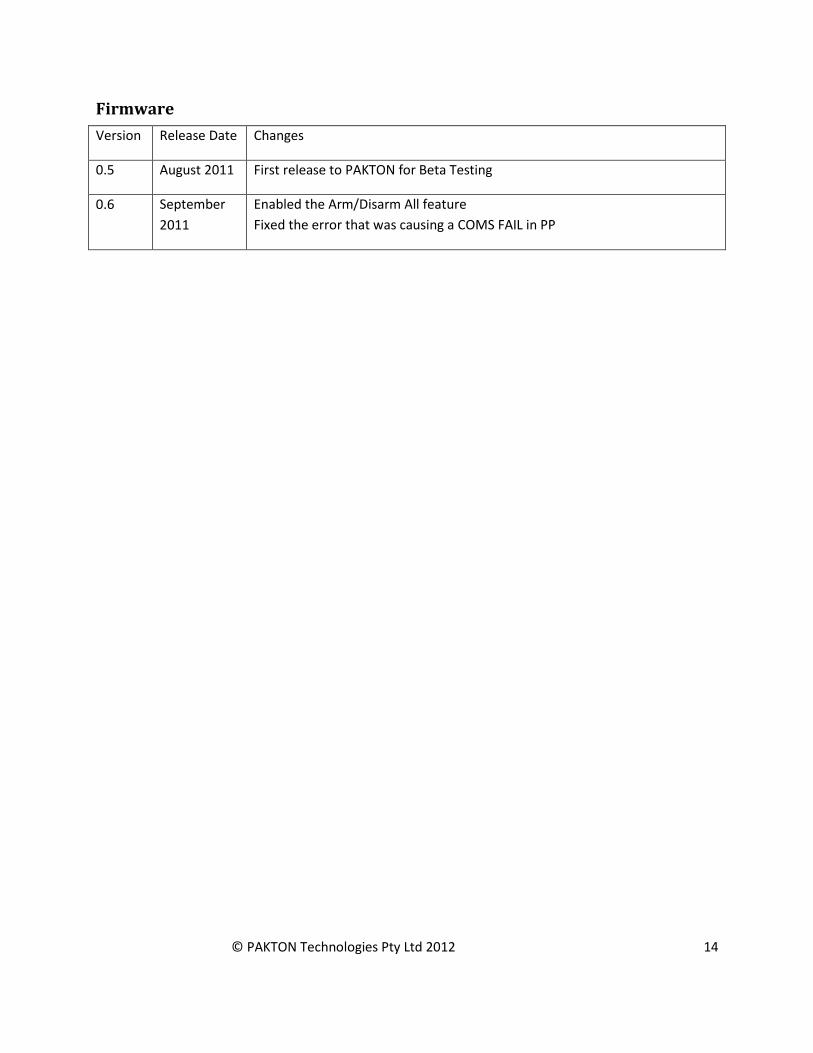
Firmware
Version Release Date Changes
0.5 August 2011 First release to PAKTON for Beta Testing
0.6 September
2011
Enabled the Arm/Disarm All feature
Fixed the error that was causing a COMS FAIL in PP


