Journal of Architecture and Planning , Vol. 32(2) , pp. 301-315, Riyadh ( 2020/1441H ) 301 Phenomenon of Penetration of Vertical Pipes into the Horizontal Mem- bers of Concrete Structure Mohammed Kaleemullah Mohammed Ali Bahobail Department of Architecture and Building Sciences, College of Architecture & Planning, King Saud University, Riyadh, Saudi Arabia. [email protected], [email protected][email protected](Received 19/9/2018; accepted for publication 10/9/2019.) Abstract: The typical types of the Riyadh’s houses are limited in villas, duplexes and low-rise apartment buildings. Most of these dwelling houses are constructed using reinforced concrete framed structures with reinforced concrete flat roof deck slabs, ribbed slabs, joist floor slab (Hordy). Unfortunately, there are some construction problems that occurred due to wrong practice by the contractors. One of these problems is what we can call “phenomenon of penetration of vertical pipes into the horizontal members such as beams and slabs of concrete structure”. This phenomenon practiced in some dwelling houses deserves consideration regarding its possible serious impact on the structure. The seriousness of this phenomenon lies in its hidden influence, which might happen suddenly or gradually, partially or totally in the form of cracking or collaps- ing. If this practice continues without evaluation, it may cause damage and severe failure in the structure. This paper emphasizes the serious effect of this practice by using a computer simulation program, which indicate that the severe cracking in the beams would make the structure and walls to fail in the course of time. Almost all the research conducted in this field is on web openings in the beams. However, a practice has been seen in Riyadh that the contractors are opening a hole vertically across the depth the beams and other structural members for easy placement of building services conduits purposes. An attempt has been made in this paper to conduct a research to evaluate the effect of opening a hole across the depth of the beam as seen in the local practice in the local construction. This incorrect construction has been discussed in this research by introducing vertical holes with different sizes and locations into the horizontal members of Con- crete Structure. Comparison has been made with correct analysis and design for different cases of holes with beams without openings using a computer program. Spacing of bars, cracking of concrete due to a vertical hole and the difficulty in the bars arrangements has been discussed. Keywords: Structure Problems, Vertical opening and structure members, Dwelling house Structure. 1. Literature review The effect of transvers opening on shear and flexure strength has been discussed. Different sizes, shapes and locations in the beam web have been considered with and without shear reinforcement. [M.A. Mansur 1998], A study also has been successfully done for accommodation of essential services by introducing web holes. Failure in shear and bending has been evolved. [M.A. Mansur 2006]. In another study Tamer has successfully undertaken to examine the potential use of externally bonded carbon fiber reinforce polymer (CFRP) composite sheets as a strengthening solution to upgrade reinforced concrete deep beams with two square openings at middle third points. [Tamer 2009], A study is also made to evaluate the behavior of the beams with transvers web opening. Also tried to strengthen the RC beams with openings using Fiber Reinforced polymer (FRP) material and steel plates. [A. Ahmed 2012]. Suggestions have been made showing the details to use the reinforcement doi:10.33948/JAP-KSU-32-2-6
Transcript
Journal of Architecture and Planning , Vol. 32(2) , pp. 301-315, Riyadh ( 2020/1441H )
301
Phenomenon of Penetration of Vertical Pipes into the Horizontal Mem-
bers of Concrete Structure
Mohammed Kaleemullah Mohammed Ali Bahobail
Department of Architecture and Building Sciences, College of Architecture & Planning, King Saud University, Riyadh, Saudi Arabia.
(Received 19/9/2018; accepted for publication 10/9/2019.)
Abstract: The typical types of the Riyadh’s houses are limited in villas, duplexes and low-rise apartment buildings. Most of these dwelling houses are constructed using reinforced concrete framed structures with reinforced concrete flat roof deck slabs, ribbed slabs, joist floor slab (Hordy). Unfortunately, there are some construction problems that occurred due to wrong practice by the contractors. One of these problems is what we can call “phenomenon of penetration of vertical pipes into the horizontal members such as beams and slabs of concrete structure”. This phenomenon practiced in some dwelling houses deserves consideration regarding its possible serious impact on the structure. The seriousness of this phenomenon lies in its hidden influence, which might happen suddenly or gradually, partially or totally in the form of cracking or collaps-ing. If this practice continues without evaluation, it may cause damage and severe failure in the structure. This paper emphasizes the serious effect of this practice by using a computer simulation program, which indicate that the severe cracking in the beams would make the structure and walls to fail in the course of time. Almost all the research conducted in this field is on web openings in the beams. However, a practice has been seen in Riyadh that the contractors are opening a hole vertically across the depth the beams and other structural members for easy placement of building services conduits purposes. An attempt has been made in this paper to conduct a research to evaluate the effect of opening a hole across the depth of the beam as seen in the local practice in the local construction. This incorrect construction has been discussed in this research by introducing vertical holes with different sizes and locations into the horizontal members of Con-crete Structure. Comparison has been made with correct analysis and design for different cases of holes with beams without openings using a computer program. Spacing of bars, cracking of concrete due to a vertical hole and the difficulty in the bars arrangements has been discussed.
Keywords: Structure Problems, Vertical opening and structure members, Dwelling house Structure.
1. Literature review
The effect of transvers opening on shear and flexure strength has been discussed. Different sizes, shapes and locations in the beam web have been considered with and without shear reinforcement. [M.A. Mansur 1998], A study also has been successfully done for accommodation of essential services by introducing web holes. Failure in shear and bending has been evolved. [M.A. Mansur 2006]. In another study Tamer has successfully
undertaken to examine the potential use of externally bonded carbon fiber reinforce polymer (CFRP) composite sheets as a strengthening solution to upgrade reinforced concrete deep beams with two square openings at middle third points. [Tamer 2009], A study is also made to evaluate the behavior of the beams with transvers web opening. Also tried to strengthen the RC beams with openings using Fiber Reinforced polymer (FRP) material and steel plates. [A. Ahmed 2012]. Suggestions have been made showing the details to use the reinforcement
doi:10.33948/JAP-KSU-32-2-6
302 Mohammed Kaleemullah, Mohammed Ali Bahobail; Phenomenon of Penetration of Vertical Pipes into the Horizontal...
around the holes. An experimental research has been done using Carbon Fiber Reinforcement Polymer (FRP) to control the cracks around the web opening, to lower the deflection and to increase ultimate capacity of beams [Abdalla 2003].
Studies by [Amorn 2010] has shown that the significant reduction in shear capacity of the beams due to the introduction of web opening. Another study of beams with web openings was made using finite element model of the RC beams and compared with the experimental tests results. [Ashraf 2012]. The web openings crossing the expected compression struts developed between the load and the supports cause approximately about 35% reduction in the beam’s capacity in all the studied cases and hence it should be avoided. However, when the introduced web opening does not interfere with the load path or stress trajectories, i.e. compression struts, the observed reduction in the beam’s capacity ranged from 6% to 8% depending on the opening dimensions therefore for an overall reduction in the beam’s capacity not exceeding 10% of the capacity of the beam without web opening [Ashraf, 2014].
Also a study has been made using Finite Element models to analyze and design to both strengthened and un-strengthened beams subjected to web openings [Rami, 2012]. Strength of concrete deep beams with different sizes of web opening also has been discussed in several research topics. It was proved that this did not affect the strength at lower loads but it was significant at higher loads [Keun-Hyeok, 2006]. An experimental study has been undertaken to rectify the reliability of the proposed equation on high-strength concrete (HSC) deep beams with various openings sizes and location in the web. [Tae-Min, 2013]. The shear or flexure failure patterns in most of the research is seen passing through the web holes of diferent sizes in most of the experimental research results [Tae-Min, 2013].
The studies by Bengi has indicated that for the beam with web openings need to be prevented from undergoing shear failure to avoid vierendeel truss action and allow to develop its ductility and bending capacity [Bengi, 2014]. Barros came up with a research to enhance the shear strength by introducing vertical and inclined bars across thebeam depth by drilling and adhesive filling [Barros, 2013].
There is still lacking in the research in the field of opening relating to introduction of ver-
tical holes. It has been shown in several studies that the inelastic behavior of Reinforced Concrete sections leads to a redistribution of moments and forces, resulting in an increased load carrying capacity of the members and the indeterminate structure. As the applied load is increased, hinges start forming in succession at locations where the hinge moment capacity is reached; with further increase in the applied load, these hinges continue to rotate until the last hinge forms converting the structure into a mechanism resulting in failure [Ali 2007].
2. Introduction:
In recent years, Riyadh underwent a huge surge in urban population growth. Buildings and facilities expanded the scope of the city, that has developed very quickly. As a result of that, construction and urbanization spread to the outskirts of the city. Housing construction is considered a large part of this movement. Most of the dwelling houses Riyadh City are constructed using reinforced concrete framed structures with reinforced concrete flat roof deck slabs or ribbed slabs (Hordy).
“The percentage use of these two types is illustrated graphically in (Abdulaziz, 2002). As can be seen from the figure, that 37% of the projects used only Joist Floor (Hordy) slabs, 7% used solid slabs, and 56% used both in the same building. These data show the wide use of Hordy slabs as they were utilized fully or partially in 38 out of the 41projects or 93% of the total”.
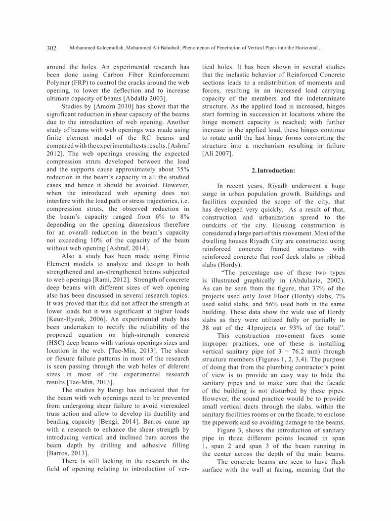
This construction movement faces some improper practices, one of these is installing vertical sanitary pipe (of 3̏ = 76.2 mm) through structure members (Figures 1, 2, 3,4). The purpose of doing that from the plumbing contractor’s point of view is to provide an easy way to hide the sanitary pipes and to make sure that the facade of the building is not disturbed by these pipes. However, the sound practice would be to provide small vertical ducts through the slabs, within the sanitary facilities rooms or on the facade, to enclose the pipework and so avoiding damage to the beams.
Figure 3, shows the introduction of sanitary pipe in three different points located in span 1, span 2 and span 3 of the beam running in the center across the depth of the main beams.
The concrete beams are seen to have flush surface with the wall at facing, meaning that the
303Journal of Architecture and Planning , Vol. 32 (2) , Riyadh ( 2020/1441H )
width of the beams is also maintained according to the wall thickness. Usually the wall thicknesses in the villas construction are used to be 25 mm and
the depth of the beams are usually used as 400 mm.Such practice of introducing a vertical hole in
the beams will weaken the structure system of the building and might produce some cracks which can be seen in the walls and in the structure member of the building. These cracks can be harmful or harmless.
“There are micro or macro cracks, and harmful or harmless cracks. The crack of width less than 0.05 mm are micro-cracks, bigger than 0.05 mm are macro-cracks. The differences between harmful and harmless cracks depend on the uses, properties, environment of building and crack position, and width. Normally the cracks bring the following consequences called harmful cracks,
Figure 1. Sanitary pipes passing across the depth of the beam and across the wall’s height
Figure 3. Introduction of pipes at several points across the depth of ground beams.
Figure 4. Beams showing the exposure of the reinforcement due to introduction of pipes across the depth of the beam.
Figure 2. Two services (Sewage and water pipes) introduced at end of the beam and column’s interior face breaking the
wall’s bond with the column.
304 Mohammed Kaleemullah, Mohammed Ali Bahobail; Phenomenon of Penetration of Vertical Pipes into the Horizontal...
such as: damage to the building function, reduce the structural stiffness, affect to the integrity of the building, damage to the surface function ofthe structure and so on” (Tommy 2012).
In fact, the cause of common cracks can be classified into following reasons:
1. Poor workmanship:
Poor mixing materials, like cement sand and aggregate, or improper steel configuration will cause cracks in beams, slabs etc.
2. Temperature variations:
Like any other materials reinforced concrete tend to expand when exposed to direct sunlight and shrinkage in cooler temperatures which might cause cracks in some situations.
3. Structural design:
Improper design and neglecting the environmental aspects, might lead to cracks in concrete works.
4. Environmental forces:
Earthquakes, winds, rains, flooding and many
other factors may cause cracking in buildings.
5. Penetration of pipe:
Cracks may also develop due to introduction of service pipes vertically in the beams and the arrangement of the reinforcement in that case would not follow the ACI code requirement due to reduction in the width.
3. STUDY METHODOLOGY:
A computer simulation program the STAAD Pro is used to investigate and explain the effect of the penetration of vertical pipes into the horizontal members of the dwelling houses of concrete structure. The size of the hole and its location will be analyzed to determine the degree of its damage. The simulation will cover different types of horizontal members with different size, lengths and different locations.
3.1 Simulation program:
The pipes have been introduced in dif-
Case No. 0 (NH) Case No. 1 (S1L-EH) Case No. 2 (S1MH)
Case No. 3 (S1R-EH) Case No. 4 (S2MH) Case No. 5 (S2R-EH)
Figure 5. Shows the parts of the building’s beam framing through which a service pipes may pass vertically, at different loca-tions.
305Journal of Architecture and Planning , Vol. 32 (2) , Riyadh ( 2020/1441H )
ferent location in the different spans. ● No hole is located in the beams. (NH)● Hole is located close to the exterior edge of
the end beam. (S1L-EH)● Hole is located in the center of the end beam.
(S1MH)● Hole is located close to the interior edge of
the end beam. (S1R-EH)● Hole is located in the center of the middle
beam. (S2MH)● Hole is located close to the right edge of the
middle beam. (S2R-EH)
3.2 Analysis and Design of the building frame:
As mentioned before, the STAAD Pro Software is chosen to operate the simulation for these reasons. A model of the frame of a two floor residential building is chosen which is assumed to have 3 bays of 5m in X and Z direction and two floors of 3.3 m high in Y direction (Figure 6). A middle beam is chosen for the study. The frame is analyzed first without any hole and compared with different cases with holes as stated above.
The introduction of a hole (for different cases as shown in figure 5) may cause a local crushing of concrete and a plastic hinge is assumed to develop, and the beam moments are readjusted due to this phenomenon [a thesis, by Zeynep, 2010]. This is due to the insufficient cross-section ofthe concrete beam.
The frame work is shown which is developed in the STAAD Pro model. The beam cross section dimensions have been chosen to reflectthe normal trend of the design offices for the residential buildings in Riyadh area as 250mm x 400mm to accommodate the walls of 250mm. This width does not increase generally more than 250mm due to architectural restriction. And the column dimensions adopted as 250mm x 250mm which is a common local practice. Normally a Compression Strength of concrete fc’ is used as 30 N/mm2.
The loads have also been calculated in general as per the trend of the consulting offices for the residential building. Therefore, the service loads: Dead Load suggested as 7.0 kN/m2 and the Live Load as 2.0 kN/m2 (for dwelling buildings) on the slabs. And the factored loads on the slab calculated to be 13.2 kN/m2 and the walls of 25 mm width with a clear height of 3.3m as 15 kN/m on the beams.
3.3 Failure Mechanism:
As the crushing of the concrete and the yeilding of reinforcement progress, lead to the formation of an elastic hinge and the redistribution of moments in the entire structure [A thesis, by Zeynep 2010].
The cracking in the beams is expected to occur 100% around the hole because of the reduction in cross-section of beam in the tension and compression zones (unlike when a hole is
Figure 6. The Framing model used in STAAD Pro of the building normally used for a residential building in Riyadh region.
306 Mohammed Kaleemullah, Mohammed Ali Bahobail; Phenomenon of Penetration of Vertical Pipes into the Horizontal...
introduced horizontally in the web). It is because the hole size would reduce the width from 250mm to 174mm by the introduction of 3” (76 mm) hole which is 30.5% of the effective width in the tension and compression zones. This generates a plastic hinge at the hole point as shown in Figure 7.
After the plastic hinge is formed, the moments are re-adjusted particularly in the case#2 and case#4. It is seen that the beams suffer larger deflections (24.22mm and 16.04mm respectively) and create close to zero positive moments at the plastic hinge and larger negative moments in the two parts connecting the plastic hinge. If this phenomenon is compared with the case#0, particularly designed for larger positive moments only to sustain the positive moments would not be sufficient to carry the larger negative moments developed after the formation of plastic hinge. This is due to the parts connecting the plastic hinge behave close to the cantilever action which needs sufficient top reinforcement also to carry higher negative moments. Therefore, these parts also start cracking in the tension zone due to insufficient top reinforcement design.
4. Results
The design of building frame has been performed for the above assumptions and the comparison of design has been discussed for different cases. Table 1 shows the results of STAAD Pro program for all cases. The comparison of Bending Moments, Steel Arearequired and the Maximum deflection and the maximum combined axial and bending stresses in
each case, has been made and evaluation of the results of the introduction of holes in different spans and different locations in the beam frame has been made.
The previous research work reveales that almost all the research work has been done on the in-troduction of web holes (Transvers holes) as shown in Figure 8. The results of the previous research has shown in all the cases (as mentioned in the litera-ture review) that the beams have cracked at the web holes. Other studies for the web hole research has shown atleast a maximum reduction of beam capac-ities upto 35 % for simple beams [Ashraf 2014].
The current study has been made for the in-troduction of vertical holes as shown in Figure 9, which effects more seriously the capacity of the beams by cracking due to shear and bending. The cracking is expected 100% because of the reduction in the tension and compression zones of the beam’s
Hole dia. 76 mm
Crushed concrete cracking forms a plastic hinge along the hole
400mm
Plan
Elevation ofbeam
87
87
76
Reinforcement
Distortion of Reinforcement
250mm
Figure 7. Showing the failure mechanism at hole point forming a plastic hinge in a beam.
Shear Cracking pattern
Figure 8. Horizontal web hole effective in Shear Crack.
307Journal of Architecture and Planning , Vol. 32 (2) , Riyadh ( 2020/1441H )
cross-section (unlike when a hole is introduced horizontally in the web). It is because the hole size would reduce the width from 250mm to 174mm by the introduction of 3” hole, which is 30.5% of effective width in the tension and compression zones. Also, this does not allow the horizontal bending moment bars for proper spacing arrange-ment maintaining the requirements of ACI code for the bar spacing. Also, the stirrups arrangement and spacing is distorted and disturbed as shown in Figure 7.
The beam width of 250mm can accommodate 4Ø16 bars without a hole, according to requirement of ACI code rebar spacing. Therefore, the introduction of vertical hole is causing a reduction of the beam width resulting to failure of the beam in Shear, Moment, Torsion and Buckling. After cracking of the concrete section at the hole would divide the beam into two parts connected by a plastic hinge giving very large deflection of these parts. This deflection goes to as maximum as 24.22 mm as shown in Table 1 in the case-2, and would surely trigger sever cracking of beams and the supported walls over these beams to occure. This process continues, in long term due to the creep of the beam and would surely damage the whole structure again to its maximum causing the worst situation of failure.
The service holes may also cause exposure of rebars due to insufficient cover provision of some of the main reinforcement. This may trigger the corrosion to start in a short time and damage the structure and cause cracking of the concrete. Figure 8 & 9 clearly shows the expected cracking pattern in case of a horizontal web holes and a
vertical hole causing shear cracks and bending cracks.
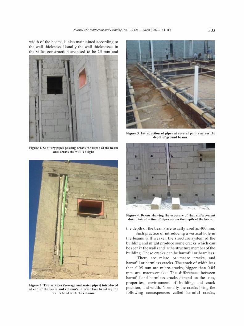
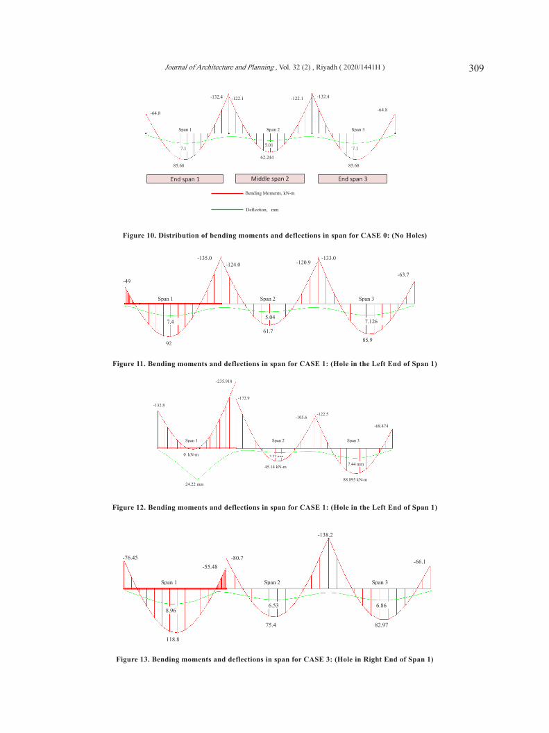
The table 1 clearly shows the difference in bending moment values, required steel reinforcement, maximum deflection and the maximum bending stresses developed in spans due to introduction of holes at different points as discussed. A uniform and symmetric distribution of bending moment and deflection is shown in Figure 10 in case of no holes present in any of the spans. Re-adjusted bending moment distribution and deflections after formation of a plastic hinge due to insertion of a service pipe holes at different locations and spans are shown in Figures 11 to 15 Maximum bending stresses has been presented in the table 2 along the beams 15 (span 1), 16 (span 2), 17 (span 3) as shown in the STAAD model.
The maximum beam stresses are found to be 20.1 N/mm2 (Figure 16), which is less than the compression strength of concrete used and safer to carry the stresses intro-duced in the concrete without any holes.
Maximum beam stresses are found to be 35.68 N/mm2 (Figure 17), which is more than the compression strength of concrete used. Concreteis failing in compression in case-2 due to introduction of vertical hole in the middle of the span-1. This case is very critical and with severe effects when compared to all other cases. The max-imum beam stresses are found to be 27.87 N/mm2(Figure 18), which is less than the compres-sion strength of concrete used and safer to carry the stresses.
5. CONCLUSIONS:
The results of the simulation program indicate that penetration of vertical pipes into the horizontal members will affect the house structure badly. This effect varies from case to case based on the location of the hole. These variations can be classified into six statuses:
1. Case 0: No hole is located in the beams
The design of the beam with width 250 mm (as usually adopted by the local constructors) is satisfactory without any hole and also sufficient for the bars arrangement across the width according to ACI code requirement which is 239 mm minimum width required in one or two
Bending Crackingpattern
Figure 9. Vertical hole effective in bending cracks.
308 Mohammed Kaleemullah, Mohammed Ali Bahobail; Phenomenon of Penetration of Vertical Pipes into the Horizontal...
Beam Nos.
Cases L-Exterior end span 1 (memb #15 STAAD Model)
L-edge Middle R-edge
Middle span 2 (memb#16 STAAD Model)
L-edge Middle R-edge
R-Exterior end span 3 (memb#17 STAAD Model)
L-edge Middle R-edge
Initi
al V
alue
s
Cas
e-0
(No
hole
s)
Max. Moments ( kN-m)
-64.8 85.76 -132.4
-122.1 62.24 -122.1
-132.4 85.76 -64.8
Required Steel (mm2)
540 730 1183 (316) (416) (616)
1080 518 1080 (616) (316) (616)
1183 730 540 (616) (416) (316)
Max. Defl. 7.1 mm 5.01 mm 7.1 mm
Max. Stress N/mm2
19.638 18.13 19.638
Re-
adju
sted
val
ues d
ue to
form
atio
n of
pla
stic
hin
ge a
t the
hol
es
Cas
e-1
(hol
e in
L-e
nd
Span
1)
Max. Moments ( kN-m)
-49.0 92.0 -135.0
-124 61.7 -120.0
-133.0 85.9 -63.76
Required Steel (mm2)
403 788.0 1210 (216) (416) (616)
1098 513 1058 (616) (316) (616)
1189 731 531 (616) (416) (316)
Max. Defl. 7.42 mm 5.04 mm 7.13 mm Max. Stress N/mm2
20.034 18.492 19.736
Cas
e-2
(hol
e in
Mid
dle-
span
1)
Max. Moments ( kN-m)
-132.8 0 -235
-172.9 45.14 -105.6
-122.5 88.9 -68.5
Required Steel (mm2)
1188 0 2446 (616) (016) (1216)
1626 370 917 (816) (216) (516)
1083 759 573 (616) (416) (316)
Max. Defl. 24.22 mm 3.34 mm 7.44 mm Max. Stress N/mm2
35.12 25.752 18.14
Cas
e-3
(R-e
nd h
ole
Span
1)
Max. Moments ( kN-m)
-76.45 118.8 -55.5
-80.7 75.4 -137.3
-136.7 82.97 -66.01
Required Steel (mm2)
645 1046 459 (416) (616) (316)
683 635 1235 (416) (416) (616)
1228 704 551 (616) (416) (316)
Max. Defl. 8.96 mm 6.53 mm 6.86 mm Max. Stress N/mm2
17.59 20.39 20.271
Cas
e-4
(hol
e in
Mid
dle-
sp
an 2
)
Max. Moments ( kN-m)
-56.87 76.5 -163.11
-184.37 0 -184.37
-163.11 76.5 -56.87
Required Steel (mm2)
471 645 1514 (316) (416) (816)
1762 0 1762 (916) (016) (916)
1514 645 471 (816) (416) (316)
Max. Defl. 5.87 mm 16.04 mm 5.88 mm Max. Stress N/mm2
24.246 27.444 24.246
Cas
e-5
(hol
e in
R-e
nd
Span
2)
Max. Moments ( kN-m)
-60.5 82.8 -142.68
-138.7 92.4 -48.56
-94.02 99.18 -76.36
Required Steel (mm2)
503 703 1291 (316) (416) (716)
1249 791 399 (616) (416) (216)
807 855 644 (416) (516) (416)
Max. Defl. 6.82 mm 6.64 mm 8.55 mm Max. Stress N/mm2
21.194 20.631 14.633
Table 1. Schedule of design for all cases of beams: (without holes and with holes)
309Journal of Architecture and Planning , Vol. 32 (2) , Riyadh ( 2020/1441H )
End span 1 Middle span 2 End span 3
-64.8
85.68
Span 1
Span 2
Span 3
62.244
85.68
-64.8
-132.4
-122.1
-122.1
-132.4
7.1
5.01
7.1
m-Nk ,Bending Moments
mm ,Deflection
Figure 10. Distribution of bending moments and deflections in span for CASE 0: (No Holes)
-49
92
-135.0
-124.0
61.7
-133.0
-120.9
85.9
-63.7
7.4
5.04
7.126
Span 1
Span 2
Span 3
Figure 11. Bending moments and deflections in span for CASE 1: (Hole in the Left End of Span 1)
-132.8
-235.918
-172.9
45.14 kN-m
88.895 kN-m
-68.474
0 kN-m
-105.6
-122.5
24.22 mm
3.33 mm
7.44 mm
Span 1
Span 2
Span 3
Figure 12. Bending moments and deflections in span for CASE 1: (Hole in the Left End of Span 1)
-76.45
118.8
-55.48 -80.7
75.4
-138.2
82.97
-66.1
8.96 6.53 6.86
Span 1 Span 2 Span 3
Figure 13. Bending moments and deflections in span for CASE 3: (Hole in Right End of Span 1)
310 Mohammed Kaleemullah, Mohammed Ali Bahobail; Phenomenon of Penetration of Vertical Pipes into the Horizontal...
-56.86
74.39
-163.11 -184.38
0 kN-m
-184.38 -163.11
74.39
-56.86
5.87
16.04 mm
5.87 mm
Span 1
Span 2
Span 3
Figure 14. Bending moments and deflections in span for CASE 4 (Hole in the Middle of Span 2)
-60.5
82.8
-142.68
-138.7
83.9
-94.024
-48.56
99.18
-76.36
6.8
6.6
8.55
Span 1
Span 2
Span 3
Figure 15. Bending moments and deflections in span for CASE 5: (Hole in the Right end of Span 2)
Case 2Compression 35.12 25.752 18.14 Failing in compressionTension -35.683 -26.137 -18.61
Case 3Compression 17.59 20.39 20.271Tension -18.059 -20.822 -20.753
Case 4Compression 24.246 27.444 24.246 Close to compression
failureTension -24.701 -27.869 -24.701
Case 5Compression 21.194 20.631 14.633Tension -21.638 -20.989 -15.123
Table 2. Beam’s combined axial and bending stresses in all the span for different hole locations
311Journal of Architecture and Planning , Vol. 32 (2) , Riyadh ( 2020/1441H )
layers. The beam stresses are within the limits of concrete compression strength.
2. Case 1: Hole is located close to the exterior edge of the end beam
Does not affect much the deflection and bend-ing moment, but it affects the shear, and bending cracks to appear. The beam stresses are with-in the limits of concrete compression strength
3. Case 2: Hole is located in the center of the end beam (span 1)
Introduction of hole in the center of the end beam causes the highest increase of bending moments, consequently increasing the steel bars to 12Ø16. Steel ratio p=0.028 is more than the p maximum allowed by the ACI code. The deflection is increased to its maximum among all cases i.e. 24.22 mm. This would crack the beam and the walls
9.5
12.6
319.6
318.1
9.1
318.1
319.6
12.6
9.5
969.-
13.1-
20.1-
518.-
0 9.-
-18.51
2mmN/
20.1-
13.1 -
969.-
7.1
7.1
5.09
Span 1
Span 2
Span 3
2mmN/ ,Bending stress, Compression
mm ,Deflection
2mmN/ Bending stress, Tension
Figure 16. Case 0: Deflection profile and maximum bending stresses in the three spans when there is no hole
6579.1
20.22-
35.12
25.752
35.68-
26.137-
6.579
6.964 -
16.037 -
18.61 -
18.14
15.652
13.1
10.039
13.569 -
10.508 -
24.223 mm-
7.443 mm
Span 1
Span 2
Span 3
Figure 17. Case 2: Deflection profile and re-adjusted maximum combined axial and bending stresses (Compression and Ten-sion) in the three spans due to the hole inserted in middle of span-1
18.3
10.9
24.25
27.44
27.44
0.21-
10.9
8.3
24.25
8.76
11.38
24.7
27.87
27.87
24.7
11.38
8.76
5.87
16.04
5.87
Figure 18. Case 4: Deflection profile and re-adjusted maximum combine axial and bending stresses (Compression and Tension) in the three spans when the hole in middle of span 2.
312 Mohammed Kaleemullah, Mohammed Ali Bahobail; Phenomenon of Penetration of Vertical Pipes into the Horizontal...
supported by this beam severely. Maximum beam stresses are found to be 35.68 N/mm2, which is more than the compression strength of concrete used.
4. Case 3: Hole is located close to the interior edge of the end beam.
Does not affect much the deflection and bending moment but it affects the shear, and bending cracks to appear.
5. Case 4: Hole is located in the center of the middle beam (span 2)
Introduction of hole in the center of the end beam causes an increase of bending moments consequently increasing the steel bars to 9Ø16. The deflection is increased to its 16.04 mm. This would also severely affect the walls supported by this beam. Maximum beam stresses are found to be 27.44 N/mm2 which is close to the compression strength of concrete used.
6. Case 5: Hole is located close to the edge of the middle beam.
Does not affect much the deflection and bending moment but it effects the shear, and cause bending cracks to appear.
Overall, the introduction of a hole in the middle span affects the design and the deflection severely, whereas the hole in the edges of the beam will have less impact.
6. SUGGETIONS
The introduction of holes affects severe-ly the beams capacity and causes cracking of the walls. The proper bars arrangement is not pos-sible using a beam width of 250 mm since the hole reduces the width to 174mm (30.5%) along the whole depth of beam. Based on the above:
● It is suggested that the beam width and the depth should be increased properly to accommodate the bars and the services holes satisfying the Code’s requirement.
● The beam has to be re-designed using a proper width and depth of the beam when the hole is decided to be introduced. This, however, increases the cost.
● Need to make further research in this field using the larger dimensions of the beam experimentally in the laboratory for simple beams making the comparison with
the beam of normal dimensions used with the allocation of holes at different locations.
● An optimized dimension ratio and a rule should be proposed by the Saudi Code so that such a practice would not damage the structure and the property life as this is the practice in Riyadh region. This rule can be used for the architectural reasons of hiding the services and fixing the facade easily. However, the sound practice would be to provide small enclosed vertical ducts through the slabs, within the sanitary facilities rooms or along the façade, to hide the pipework and so avoiding damage to the beams.
● The service holes may also cause exposure and leaves insufficient concrete cover for some of the main reinforcement. This may trigger the corrosion to start in a short time and damage the structure and cracking of the concrete due to the rebar corrosion. Protec-tion of the corrosion process should also be taken care of by the Standards.
● Care should be taken not to create a distortion of main reinforcement reducing the design capacity.
7. References:
Ali Kheyroddin,” Plastic Hinge Rotation Ca-pacity of Reinforced Concrete Beams”, International Journal of Civil Engineer-ing. Vol. 5, No. 1, March 2007. 30-47 P.
Abdulaziz I. Al-Negheimish1, Ahmad B. Shu-raim1 and Abdullah S. Al-Tayyar2, “Structural Design Practice For Resi-dential Buildings In Riyadh: An Over-view”, The 6th Saudi Engineering Confer-ence, KFUPM, Dhahran, December 2002.
Ashraf Ragab Mohamed, Mohie S. Shoukry, Janet M. Saeed,” Prediction of the be-havior of reinforced concrete deep beams with web openings using the fi-nite element method”, Alexandria En-gineering Journal (2014) 53, 329–339.
A. Ahmed a, M.M. Fayyadh b, S. Naganathan a, K. Nasharuddin, “Reinforced concrete beams with web openings: A state of the art review”, Materials and Design, (2012),40, 90–102.
Ashraf Mohamed Mahmoud, “Strengthen-ing of concrete beams having shear zone
313Journal of Architecture and Planning , Vol. 32 (2) , Riyadh ( 2020/1441H )
openings using orthotropic CFRP mod-eling”, Ain Shams Engineering Jour-nal, 3, 177–190, (2012). www.elsevier.com/locate/asej.www.sciencedirect.com
Amorn Pimanmas,” Strengthening R/C beams with opening by externally installed FRP rods:Behavior and analysis”, Compos-ite Structures 92, 1957-1976, (2010).www.elsevier.com/locate/compstruct
Building Code Requirement for Struc-tural Concrete ( ACI 318M-14) and Commentary (ACI 318 RM-14).
Bengi Aykac, Sabahattin Aykac, Ilk-er Kalkan, Berk Dundar, and Husnu Can,” Flexural Behavior and Strength of Reinforced Concrete Beams with Multiple Transverse Openings”, ACI Struc-tural Journal, 267-277, (March- April 2014).
H. A. Abdalla, A.M. Torkey, H.A. Haggag, A.F. Abu-Amira, “Design against cracking at openings in reinforced concrete beams strengthened with composite sheets”, Com-posite Structures 60, 197-204, (2003). www.elsevier.com/locate/compstruct
J. A. O. Barros and G. M. Dalfre, “Assessment of the Effectiveness of the Embedded-Through-Section Technique for the Shear Strengthening of Reinforced Concrete Beams”,Strain, An International Journal for Experimental Mechanics, 75-93 (2013).
Kokil Jaidka Christopher S.G. Khoo Jin-Cheon Na, “Literature review writing: how information is slected and trans-formed”, Aslib Proceedings, Vol.65 Iss 3 pp.303-325, (2013). http://dx.doi.org/10.1108/00012531311330665
Keun-Hyeok Yang, Hee-Chang Eun, Heon-Soo Chung,” The influence of web open-ings on the structural behavior of rein-forced high-strength concrete deep beams”, Engineering Structures 28 1825–1834 (2006), www.elsevier.com/locate/engstruct
Kostiantyn Protchenkoa*, Maria Wlodarczyka,Elzbieta Szmigiera, Inves-tigation of behavior of reinforced concrete elements strengthened with FRP”, XXIV R-S-P seminar, Theoretical Foundation of Civil Engineering (24RSP) (TFoCE 2015),
Procedia Engineering 111 ( 2015 ) 679 – 686.
Lukasz zdanowicz, Ryszard wojdak, “ Struc-tural Analysis Of A Failured Rc Beam With Openings In A Building Under Con-struction”, Technical Transactions Civ-il Engineering 2-B, 157-168, 2013.
M. A. Mansur, Kiang-Hwee Tan,” Concrete Beams with Openings Analysis and Design”, Book published in Jan 29, 1999, CRC press.
M. A. Mansur, “Effect of Openings on the Be-haviour and Strength of R/C Beams in Shear”,Cement and Concrete Com-posite 20 (1998), 477-486, (1998).
M.A. Mansur, “Design Of Reinforced Con-crete Beams With Web Openings”, Pro-ceedings of the 6th Asia-Pacific Struc-tural Engineering and Construction Conference (APSEC 2006), 5 – 6 Septem-ber 2006, Kuala Lumpur, Malaysia,(2006).
Naga Chaitanya C, Vamsi Krishna B, “ An Ex-perimental Study of Flexural Strength of Reinforced Concrete Beam Due To Corrosion”, IOSR Journal of Mechani-cal and Civil Engineering (IOSR-JMCE) e-ISSN: 2278-1684,p-ISSN: 2320-334X, Volume 11, Issue 4 Ver. II (Jul- Aug. 2014), PP 98-109 (www.iosrjournals.org)
Rami A. Hawileh, Tamer A. El-Maaddawy, Mohannad Z. Naser, “ Nonlinear fi-nite element modeling of concrete deep beams with openings strengthened with externally-bonded composites”, Mate-rials and Design 42, 378–387, (2012).
Tamer El Maaddawy, Sayed Sherif, “FRP com-posites for shear strengthening of reinforced concrete deep beams with openings”,-Composite Structure 89, 60-69, (2009).
Tae-Min Yoo, Jeung-Hwan Doh, Hong Guan1 and Sam Fragomeni,” Experimental be-haviour of high-strength concrete deep beams with web openings” , The structural design of tall and special buildings struc-ture. Design Tall Spec. Build. 22, 655–676 (2013), Published online 4 August 2011.
Tommy Bendix Villadsen, Consultant: VIA Uni-versity College, Horsens, Denmark, Novem-ber 2012. Date Defended: April 26, 2010.
314 Mohammed Kaleemullah, Mohammed Ali Bahobail; Phenomenon of Penetration of Vertical Pipes into the Horizontal...
Wen-Yao Lu, Ing-Jaung Lin, and Hsin-Wan Yu, “Shear Strength of Reinforced Con-crete Deep Beams”, ACI Structural Journal, 671-680, (July-August 2013).
Zeynep Firat Alemdar, “Plastic Hinging Be-havior Of Reinforced Concrete Bridge Columns”, Submitted to the graduate de-gree program in Civil Engineering and the Graduate Faculty of the University of Kan-sas in partial fulfillment of the require-ments for the degree of Doctor of Philos-ophy. Date Defended: April 26, (2010)
315Journal of Architecture and Planning , Vol. 32 (2) , Riyadh ( 2020/1441H )
ظاهرة اخراق الأنابيب العمودية لعناصر الهيكل الإنشائي الأفقية
محمد كليم الله محمد علي باحبيل
قسم العمارة وعلوم البناء، كلية العمارة والتخطيط، جامعة الملك سعود، الرياض،المملكة العربية السعودية.
قدم للنشر في 1440/1/9هـ ؛ وقبل للنشر في 1441/1/11هـ.
ملخص البحث. تتكون معظم منازل الرياض من الفلل والدوبلكس أو الشقق. ويتم بناء معظم هذه المنازل أو بلاطات المكونة من الأعمدة والكمرات وبلاطات مستوية المسلحة باستخدام هياكل الخرسانة السكنية معصبة ribbed slab )هوردي(. ولكن لسوء الحظ، هناك عدد من المشاكل الإنشائية ظهرت بسبب الممارسات الخاطئة للمقاولين. احدى هذه المشاكل هي ما يمكن أن نسميه »ظاهرة تغلغل الأنابيب الرأسية في العناصر الوحدات من كثير في الظاهرة هذه وتمارس السقف. وبلاطات الجسور مثل: الإنشائي للهيكل الأفقية السكنية، متجاهلين خطورتها وتأثيرها على صلابة الهيكل الإنشائي للمبنى. وتكمن خطورة هذه الظاهرة في تأثيرها الخفي، الذي قد يحدث فجأة أو تدريجياً، جزئياً أو كلياً في شكل من أشكال التصدع أو الانهيار. وإذا تركت هذه الصدوع دون علاج فأنه بمرور الزمن قد تؤدي إلى انهيار كامل للهيكل. تبحث هذه الورقة مدى التأثير الخطير لهذه الظاهرة على الهيكل الإنشائي للمبنى من خلال استخدام برنامج محاكاة حاسوبي ، والذي أكد إلى أن التصدع الحاد في الجسور سيجعل الهيكل والجدران مع مرور الوقت عرضة للانهيار. ركزت هذه الورقة على دراسة وتقويم تأثير وجود ثقوب رأسية عب جسور الهيكل الإنشائي، من خلال دراسة عدد من
الثقوب الرأسية بأحجام ومواقع مختلفة. تم إخضاعها الى عملية تحليلية باستخدام الحاسب الآلي.
الكلات المفتاحية: المشاكل الانشائية، الفتحات الرأسية في العناصر الانشائية، هيكل المسكن.