APPLIED OPTIC S Photodetecting Instrument with Flat Wavelength Response* PAULM. MCPHERSON McPherson Instrument Corporation, Acton, Massachusetts NATHAN SCLARt AND BERNARD R. LINDEN: Allen B. DuMont Laboratories, Inc., Clifton, New Jersey WILLEaIBROUWER§ Physics Department, Boston University, Boston, Massachusetts AND A. T. STAIR, JR. Thermal Radiation Laboratory, Geophysics Research Directorate, Air Force Cambridge Research Laboratories, Bedford, Massachusetts (Received December 6, 1960) Photosensitive instruments which measure absolute irradiance in four spectral bands (2000-2500 A, 2500-4000 A, 4000-5000 A, and 5000-10 000 A) are described. One instrument is used to cover each range. The basic unit is a prism-type spectrometer that weighs 2 lb and measures 11 by 15 in. This compact pack- aging is achieved by the use of a unique single prism that produces a straight-through optical axis. The spectral cutoffs are sharp and the electrical output is constant for a given flux of any wavelength distribution within the spectral passband. The passband with sharp wavelength cutoffs and a flat response versus wave- length is accomplished by the use of a mask with variable aperture placed in the focal plane. Microsecond response time is obtained through the use of a 4-in. phototube detector which is used as a photomultiplier or photodiode, depending upon sensitivity requirements. INTRODUCTION IN monitoring sources of ultraviolet, visible, and infrared energy, there has long been a need for a spectroradiometer with a "tunable" filter to give flat electrical response versus wavelength and controllable spectral passbands with sharp cutoffs. Such an instru- ment would be valuable for measuring absolute spectral irradiances. Bolometers, radiometers, and calorimeters have been developed to measure broad-band spectral irradiance or total thermal energy, but these have vari- ous handicaps such as slow response times and lack of spectral definition. The instrument described herein was developed initially for measuring the thermal energy from nuclear detonations (thermal in this instance refers to energy of wavelengths from 2000 A through the infrared). The thermal pulse from nuclear explosions is a rapidly varying transient with characteristic double maxima for sea level bursts. The first maximum has a rise time of microseconds, while the total pulse may last for * Developed for the Thermal Radiation Laboratory, Air Force Cambridge Research Laboratories, Bedford, Massachusetts under contracts with McPherson Precision Instruments, Acton, Massachusetts and Allen B. Du Mont Laboratories, Inc., Clifton, New Jersey. t Present address: Nuclear Corporation of America, Denville, New Jersey. I Present address: C.B.S. Laboratories, Inc., Stamford, Connecticut. § Present address: Diffraction Limited, Inc., Natick, Massachusetts. seconds.' The spectral distribution and magnitude of the radiant energy from such an explosion may be strongly affected by different environments and the intervening atmosphere. In addition to the requirement of obtaining absolute spectral irradiances from unknown fast-transient sources, the instrument needed to be rugged, small, and lightweight for field use. Instrument platforms were to be aircraft, balloon-borne canisters, and rockets. Com- pact packaging was also required to be able to use a number of units per station, thereby monitoring (in adjacent bands) a wide spectral region and achieving a range in recording levels. The instrument is basically a prism-type spectrom- eter with a phototube detector which features a mask in the focal plane to provide sharp wavelength cutoffs and to compensate for variation in electrical response with wavelengths. A schematic drawing of a typical unit is shown in Fig 1. The unit is straight, weighs 2 lb and measures 12X 12X 15 in. A set of four instruments (hereafter referred to as dispersion units) have been developed to monitor the region 2000-10 000 A. Each instrument covered one of the following ranges: far ultraviolet (fuv), 2000-2500 A; near ultraviolet (nuv), 2500-4000A; visible (vis), 4000-5000 A; and near infrared (nir), 5000-10 000 A. This spectral breakdown was chosen for the particular interests of the Thermal I Samuel Glasstone, Air Force Pamphlet 136-1-3 (U. S. Atomic Energy Commission, June, 1957). 767
Transcript
APPLIED OPTIC SPhotodetecting Instrument with Flat Wavelength Response*
PAUL M. MCPHERSONMcPherson Instrument Corporation, Acton, Massachusetts
NATHAN SCLARt AND BERNARD R. LINDEN:Allen B. DuMont Laboratories, Inc., Clifton, New Jersey
WILLEaI BROUWER§Physics Department, Boston University, Boston, Massachusetts
AND
A. T. STAIR, JR.Thermal Radiation Laboratory, Geophysics Research Directorate, Air Force Cambridge Research Laboratories, Bedford, Massachusetts
(Received December 6, 1960)
Photosensitive instruments which measure absolute irradiance in four spectral bands (2000-2500 A,2500-4000 A, 4000-5000 A, and 5000-10 000 A) are described. One instrument is used to cover each range.The basic unit is a prism-type spectrometer that weighs 2 lb and measures 11 by 15 in. This compact pack-aging is achieved by the use of a unique single prism that produces a straight-through optical axis. Thespectral cutoffs are sharp and the electrical output is constant for a given flux of any wavelength distributionwithin the spectral passband. The passband with sharp wavelength cutoffs and a flat response versus wave-length is accomplished by the use of a mask with variable aperture placed in the focal plane. Microsecondresponse time is obtained through the use of a 4-in. phototube detector which is used as a photomultiplieror photodiode, depending upon sensitivity requirements.
INTRODUCTION
IN monitoring sources of ultraviolet, visible, andinfrared energy, there has long been a need for a
spectroradiometer with a "tunable" filter to give flatelectrical response versus wavelength and controllablespectral passbands with sharp cutoffs. Such an instru-ment would be valuable for measuring absolute spectralirradiances. Bolometers, radiometers, and calorimetershave been developed to measure broad-band spectralirradiance or total thermal energy, but these have vari-ous handicaps such as slow response times and lack ofspectral definition.
The instrument described herein was developedinitially for measuring the thermal energy from nucleardetonations (thermal in this instance refers to energyof wavelengths from 2000 A through the infrared). Thethermal pulse from nuclear explosions is a rapidlyvarying transient with characteristic double maximafor sea level bursts. The first maximum has a rise timeof microseconds, while the total pulse may last for
* Developed for the Thermal Radiation Laboratory, Air ForceCambridge Research Laboratories, Bedford, Massachusetts undercontracts with McPherson Precision Instruments, Acton,Massachusetts and Allen B. Du Mont Laboratories, Inc., Clifton,New Jersey.
t Present address: Nuclear Corporation of America, Denville,New Jersey.
I Present address: C.B.S. Laboratories, Inc., Stamford,Connecticut.
seconds.' The spectral distribution and magnitude ofthe radiant energy from such an explosion may bestrongly affected by different environments and theintervening atmosphere.
In addition to the requirement of obtaining absolutespectral irradiances from unknown fast-transientsources, the instrument needed to be rugged, small, andlightweight for field use. Instrument platforms were tobe aircraft, balloon-borne canisters, and rockets. Com-pact packaging was also required to be able to use anumber of units per station, thereby monitoring (inadjacent bands) a wide spectral region and achievinga range in recording levels.
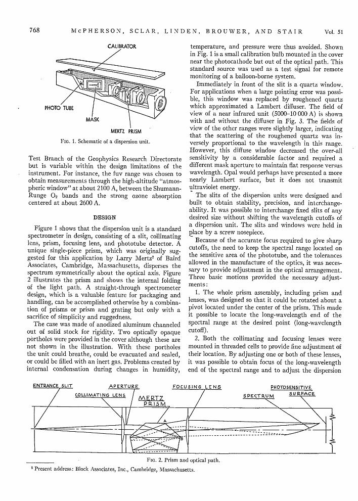
The instrument is basically a prism-type spectrom-eter with a phototube detector which features a maskin the focal plane to provide sharp wavelength cutoffsand to compensate for variation in electrical responsewith wavelengths. A schematic drawing of a typical unitis shown in Fig 1. The unit is straight, weighs 2 lb andmeasures 12 X 12 X 15 in. A set of four instruments(hereafter referred to as dispersion units) have beendeveloped to monitor the region 2000-10 000 A. Eachinstrument covered one of the following ranges: farultraviolet (fuv), 2000-2500 A; near ultraviolet (nuv),2500-4000A; visible (vis), 4000-5000 A; and nearinfrared (nir), 5000-10 000 A. This spectral breakdownwas chosen for the particular interests of the Thermal
I Samuel Glasstone, Air Force Pamphlet 136-1-3 (U. S. AtomicEnergy Commission, June, 1957).
767
McPHERSON, SCLAR, LINDEN, BROUWER, AND STAIR
PHOTO TUBE I
MASK
MERTZ PRISM
FIG. 1. Schematic of a dispersion unit.
Test Branch of the Geophysics Research Directoratebut is variable within the design limitations of theinstrument. For instance, the fuv range was chosen toobtain measurements through the high-altitude "atmos-pheric window" at about 2100 A, between the Shumann-Runge 02 bands and the strong ozone absorptioncentered at about 2600 A.
DESIGN
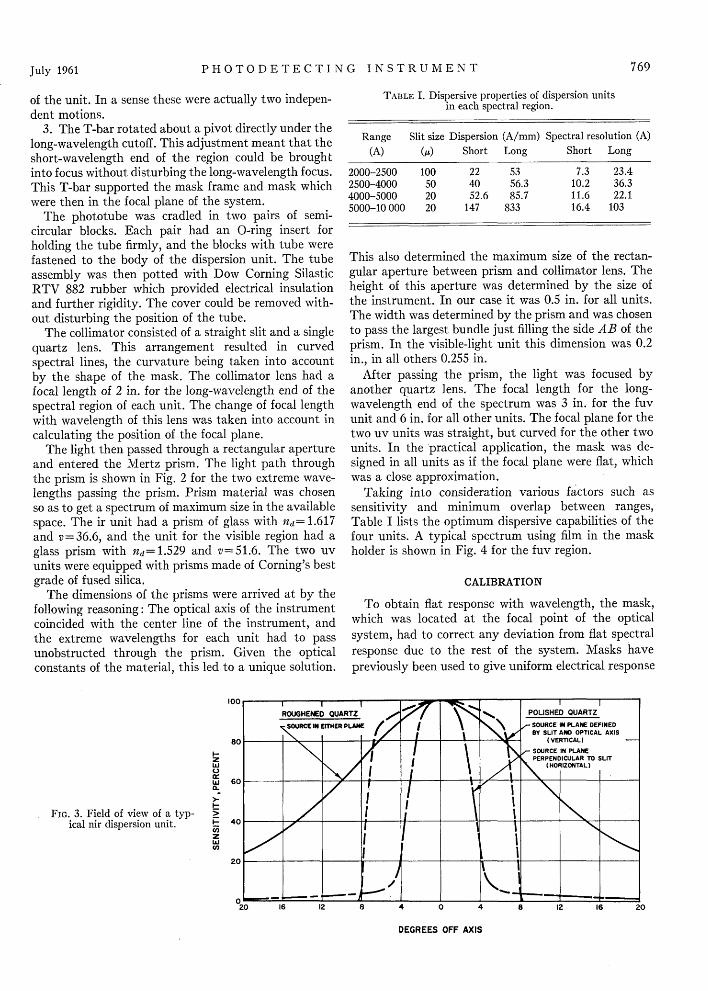
Figure 1 shows that the dispersion unit is a standardspectrometer in design, consisting of a slit, collimatinglens, prism, focusing lens, and phototube detector. Aunique single-piece prism, which was originally sug-gested for this application by Larry Mertz2 of BairdAssociates, Cambridge, Massachusetts, disperses thespectrum symmetrically about the optical axis. Figure2 illustrates the prism and shows the internal foldingof the light path. A straight-through spectrometerdesign, which is a valuable feature for packaging andhandling, can be accomplished otherwise by a combina-tion of prisms or prism and grating but only with asacrifice of simplicity and ruggedness.
The case was made of anodized aluminum channeledout of solid stock for rigidity. Two optically opaqueportholes were provided in the cover although these arenot shown in the illustration. With these portholesthe unit could breathe, could be evacuated and sealed,or could be filled with an inert gas. Problems created byinternal condensation during changes in humidity,
temperature, and pressure were thus avoided. Shownin Fig. 1 is a small calibration bulb mounted in the covernear the photocathode but out of the optical path. Thisstandard source was used as a test signal for remotemonitoring of a balloon-borne system.
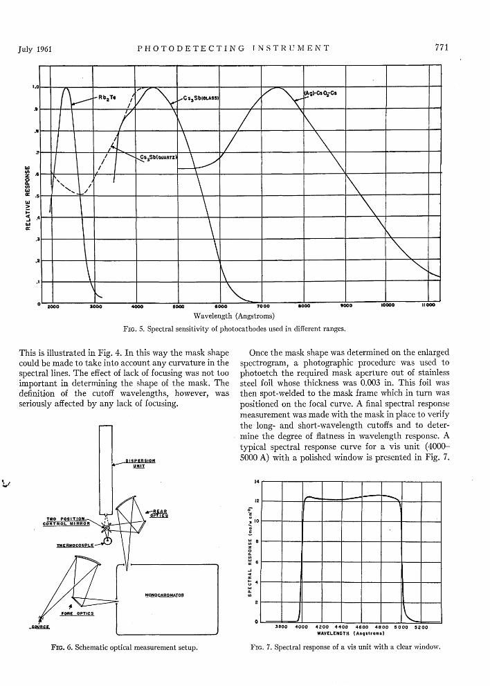
Immediately in front of the slit is a quartz window.For applications when a large pointing error was possi-ble, this window was replaced by roughened quartzwhich approximated a Lambert diffuser. The field ofview of a near infrared unit (5000-10 000 A) is shownwith and without the diffuser in Fig. 3. The fields ofview of the other ranges were slightly larger, indicatingthat the scattering of the roughened quartz was in-versely proportional to the wavelength in this range.However, this diffuse window decreased the over-allsensitivity by a considerable factor and required adifferent mask aperture to maintain flat response versuswavelength. Opal would perhaps have presented a morenearly Lambert surface, but it does not transmitultraviolet energy.
The slits of the dispersion units were designed andbuilt to obtain stability, precision, and interchange-ability. It was possible to interchange fixed slits of anydesired size without shifting the wavelength cutoffs ofa dispersion unit. The slits and windows were held inplace by a screw nosepiece.
Because of the accurate focus required to give sharpcutoffs, the need to keep the spectral range located onthe sensitive area of the phototube, and the tolerancesallowed in the manufacture of the optics, it was neces-sary to provide adjustment in the optical arrangement.Three basic motions provided the necessary adjust-ments:
1. The whole prism assembly, including prism andlenses, was designed so that it could be rotated about apivot located under the center of the prism. This madeit possible to locate the long-wavelength end of thespectral range at the desired point (long-wavelengthcutoff).
2. Both the collimating and focusing lenses weremounted in threaded cells to provide fine adjustment oftheir location. By adjusting one or both of these lenses,it was possible to obtain focus of the long-wavelengthend of the spectral range and to adjust the dispersion
of the unit. In a sense these were actually two indepen-dent motions.
3. The T-bar rotated about a pivot directly under thelong-wavelength cutoff. This adjustment meant that theshort-wavelength end of the region could be broughtinto focus without disturbing the long-wavelength focus.This T-bar supported the mask frame and mask whichwere then in the focal plane of the system.
The phototube was cradled in two pairs of semi-circular blocks. Each pair had an 0-ring insert forholding the tube firmly, and the blocks with tube werefastened to the body of the dispersion unit. The tubeassembly was then potted with Dow Corning SilasticRTV 882 rubber which provided electrical insulationand further rigidity. The cover could be removed with-out disturbing the position of the tube.
The collimator consisted of a straight slit and a singlequartz lens. This arrangement resulted in curvedspectral lines, the curvature being taken into accountby the shape of the mask. The collimator lens had afocal length of 2 in. for the long-wavelength end of thespectral region of each unit. The change of focal lengthwith wavelength of this lens was taken into account incalculating the position of the focal plane.
The light then passed through a rectangular apertureand entered the Mertz prism. The light path throughthe prism is shown in Fig. 2 for the two extreme wave-lengths passing the prism. Prism material was chosenso as to get a spectrum of maximum size in the availablespace. The ir unit had a prism of glass with nd= 1.617and v=36.6, and the unit for the visible region had aglass prism with nd=1.529 and v=51.6. The two uvunits were equipped with prisms made of Corning's bestgrade of fused silica.
The dimensions of the prisms were arrived at by thefollowing reasoning: The optical axis of the instrumentcoincided with the center line of the instrument, andthe extreme wavelengths for each unit had to passunobstructed through the prism. Given the opticalconstants of the material, this led to a unique solution.
100 I I
ROUGHENED OU
SOURCE IN ErTHEI
C.)w 60
FIG. 3. Field of view of a typ-ical nir dispersion unit.
I-
c-
U,
TABLE I. Dispersive properties of dispersion unitsin each spectral region.
Range Slit size Dispersion (A/mm) Spectral resolution (A)
This also determined the maximum size of the rectan-gular aperture between prism and collimator lens. Theheight of this aperture was determined by the size ofthe instrument. In our case it was 0.5 in. for all units.The width was determined by the prism and was chosento pass the largest bundle just filling the side AB of theprism. In the visible-light unit this dimension was 0.2in., in all others 0.255 in.
After passing the prism, the light was focused byanother quartz lens. The focal length for the long-wavelength end of the spectrum was 3 in. for the fuvunit and 6 in. for all other units. The focal plane for thetwo uv units was straight, but curved for the other twounits. In the practical application, the mask was de-signed in all units as if the focal plane were flat, whichwas a close approximation.
Taking into consideration various factors such assensitivity and minimum overlap between ranges,Table I lists the optimum dispersive capabilities of thefour units. A typical spectrum using film in the maskholder is shown in Fig. 4 for the fuv region.
CALIBRATION
To obtain flat response with wavelength, the mask,which was located at the focal point of the opticalsystem, had to correct any deviation from flat spectralresponse due to the rest of the system. Masks havepreviously been used to give uniform electrical response
DEGREES OFF AXIS
769July 1961
McPHERSON, SCLAR, LINDEN, BROUWER, AND STAIR
FIG. 4. Mercury spectrum obtained with an fuv unitwith superimposed mask.
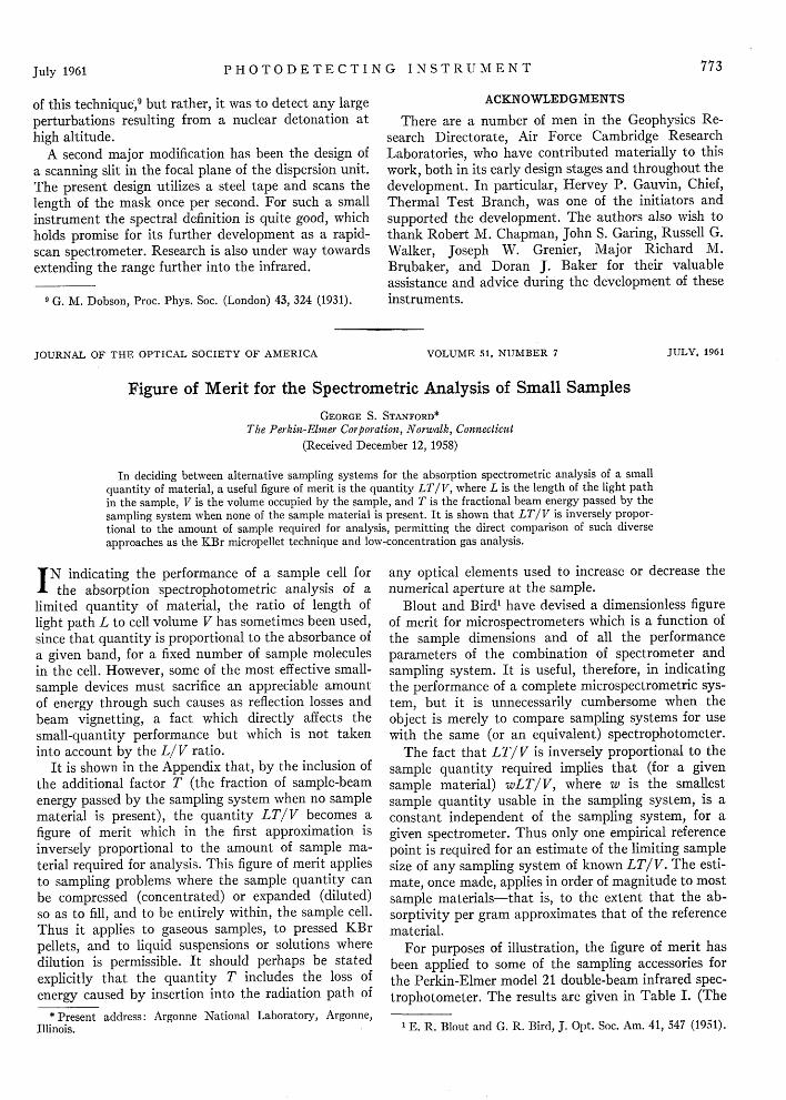
versus wavelength' and the technique is quite straight-forward, but in practice, obtaining uniform responseand sharp cutoffs was difficult. The most importantcause of selective spectral response was the wavelengthdependence of the photocathode surfaces themselves.Typical response curves for the photosurfaces used inthe various spectral ranges are shown in Fig. 5. Theseplots are presented on a single graph for convenience anddo not represent their relative responses. The curvespeak at various wavelengths and fall rather sharply oneither side.
Other factors affecting the wavelength response wereabsorption, aberrations, and scattering in the optics ofthe system.
The experimental method of making the mask tookall of the above factors into account. The shape of the
I Gen. Elec. Rev. 52, 34 (1949).
mask aperture was determined by measuring the re-sponse of the complete unit as a function of wavelength.Since the spectrum was dispersed along the focal planein a known manner, it was possible to vary the verticaldimension of the open aperture along its length to makethe response flat over the desired wavelength range.Thus, the vertical dimension of the open aperture variedessentially as the reciprocal of the measured wavelengthresponse. It is evident that the over-all sensitivity waslimited by the sensitivity at the wavelength yieldingleast response. In each of the four units, the wavelengthof least response generally fell at one end or the other ofthe spectral region.
Twenty-five dispersion units in each of the fourranges were made. It was necessary to treat each unitindividually; that is, the use of a master mask for eachrange was not feasible because of variations in cathoderesponse.
Figure 6 shows a sketch of the experimental arrange-ment for calibration of the units. A two-position mirrorwas used with the rear optics to send the monochromaticenergy onto either the standard detector or the disper-sion unit. This kept the optical paths the same.
A thermocouple detector was used as a standard withflat spectral response for all regions except the fuv. Inthis region a photomultiplier coated with sodiumsalicylate was used to gain sufficient sensitivity sinceavailable sources were not very intense in the fuv.Johnson, Watanabe, and Tousey4 showed that thiscombination is a relatively flat quantum detectorthrough the wavelength region 1000-2300 A. Thesodium salicylate coated photomultiplier was found tobe useful as a flat standard up to 2500 A.
The first step in calibration was focusing of theindividual units. Proper focusing determined the sharp-ness of the cutoffs and affected the degree to which theresponse could be made flat. As described earlier, aseries of adjustments was provided for focusing a unit.The method involved taking a number of film spectro-grams. First the long-wavelength end was brought intofocus right at the pivot point of the mask. The maskframe was then rotated to bring the short-wavelengthend into focus. In practice, the focusing procedureproved to be quite tedious and time-consuming.
Once focusing had been accomplished, the spacingsbetween lines of known wavelength were used to deter-mine the wavelength distribution along the mask plane.For the uv regions a mercury arc was used. For thevisible and ir regions a tungsten lamp in combinationwith a simple grating monochromator served as a sourceof energy of known wavelength.
Prints of the individual spectrograms magnified tentimes were then prepared. The calculated mask aper-tures were drawn on each print symmetrically abouta line bisecting the vertical aperture of the mask frame.
I F. S. Johnson, K. Watanabe, and R. Tousey, J. Opt. Soc. Am.41, 702 (1951).
770
ORWia,
Vol. 51
-1849
PHOTODETECTING INSTRUMENT
6000 7000
Wavelength (Angstroms)
FIG. 5. Spectral sensitivity of photocathodes used in different ranges.
This is illustrated in Fig. 4. In this way the mask shapecould be made to take into account any curvature in thespectral lines. The effect of lack of focusing was not tooimportant in determining the shape of the mask. Thedefinition of the cutoff wavelengths, however, wasseriously affected by any lack of focusing.
SORCE
FIG. 6. Schematic optical measurement setup.
Once the mask shape was determined on the enlargedspectrogram, a photographic procedure was used tophotoetch the required mask aperture out of stainlesssteel foil whose thickness was 0.003 in. This foil wasthen spot-welded to the mask frame which in turn waspositioned on the focal curve. A final spectral responsemeasurement was made with the mask in place to verifythe long- and short-wavelength cutoffs and to deter-mine the degree of flatness in wavelength response. Atypical spectral response curve for a vis unit (4000-5000 A) with a polished window is presented in Fig. 7.
232 - --
I2
0 e-
6~4- _
3800 4000 4200 4400 4600 4800 5000 5200
WAVELENGTH Angstroms)
F IG. 7. Spectral response of a vis unit with a clear window.
z
a:I--j
W
771July 1961
McPHERSON, SCLAR, LINDEN, BROUWER, AND STAIR
TABLE II. Typical characteristics of calibrated units with diffuse windows.
Some characteristics of calibrated units with diffusewindows are presented in Table II.
The uncertainty in cutoff wavelength was defined asthe spread in wavelengths over which the response ofthe unit fell 90-10% of the response just before cutoffbegan. A thermocouple was used as a secondary stand-ard to calibrate each unit in terms of microamperes perwatt of incident radiant flux per square centimeter.
PHOTOTUBES AND ELECTRICAL MEASUREMENTS
In order to fit the phototube into the small aluminumboxes of the dispersion units it was necessary to usespecial -in. tubes. The photocathodes of Rb2Te, CsSb(quartz), CsSb (glass), and (Ag)-Cs0 2-Cs, whosespectral sensitivities are shown in Fig. 5, were used,respectively, in ranges fuv, nuv, vis, and nir.
The units were designed so that either photodiodesor photomultipliers could be used as the detector. Theadvantage of operating with photodiodes instead ofphotomultipliers is twofold: First, their electrical out-put is linear over large irradiance ranges and second,the response is relatively insensitive to small fluctua-tions in the voltage, once a certain minimum value ofvoltage has been applied. However, the large gain insensitivity realized by photomultiplier tubes is in-valuable in many applications. In the laboratory, infact, it is necessary to use photomultipliers in the ir andfuv ranges for calibration purposes. To gain the advan-tages of both, all units were equipped with photomulti-pliers, and by arrangement of pin connections andspecial adapters the tube could be operated as either amultiplier or a diode with the first dynode acting as theanode. The spectral response was, of course, independentof the mode of operation. Six-stage photomultiplierswere used in all ranges except the fuv. For that range a10-stage photomultiplier was needed because of thesmaller amounts of energy available in laboratorysources.
The dispersion units were tested to determine theirability to function satisfactorily at high altitudes. Forthe units used as photodiodes, preliminary trials with500 v indicated breakdown between pin connections atabout 90 000 ft. Accordingly, all the pin connectionswere packed with the Dow-Corning compound No. 4,a jellylike material. The tests on all the units using thismaterial indicated no breakdown at any altitude up to90 000 ft above sea level. This Dow-Corning compound,
according to information supplied by the manufacturer,maintains its physical and insulation properties withinthe temperature range of - 70° to 400F.
SPECIAL MODIFICATIONS
Some special requirements arose from consideringclose-in measurements of nuclear bursts. First, theirradiance was expected to be so high that the responseof the phototubes would not be linear even as diodes,and second, ordinary glass colors under high gamma orneutron flux.5 To overcome the first difficulty, theradiant flux striking the surface had to be reduced. Theproblem of finding a spectral filter nonselective over thewavelengths of interest as well as being able to vary thetransmittance was solved by the use of metal screens.6
Screen disks were mounted (when required) in front ofthe slit by modifying the nosepiece to hold one or moreat either end. These screens consisted of uniformlyelectroplated nickel with conical holes and had a rangeof transmittance between 1 and 50%.7 By a combinationof screens, smaller transmittances could be obtained;however, extreme care had to be taken not to introducemoir6 effects.
The problem of glass coloration was partially solvedby the development of cerium-protected glass." A highquality batch of "protected" crown flint glass, 529 :516,was developed by Dr. N. J. Kreidl of Bausch & LombOptical Company. The dense flint, 617:366, was alreadydeveloped, but it was necessary to produce a bettergrade for good optical work.
One modified usage of the instrument was to make aspectrophotometer for measuring any large changes inthe amount of atmospheric ozone by monitoring thevariation in uv absorption of solar energy. This wasdone by modifying two units to have solid masksexcept for a 70-A slit located at approximately 3050 Ain one and 3250 A in the other. A change in the ratio ofthe two readings would indicate a change in the amountof ozone since this is on the shoulder of a strong ozoneabsorption band. This instrument did not purport todetect slight variations in ozone as did the original use
I G. S. Monk, Argonne Nat. Lab. Rept. ANL-4336 (1950).6 L. J. Heidt and D. E. Bosley, J. Opt. Soc. Am. 43, 760 (1953).7 Pyramid Screen Corporation, 181 Harvard, Brighton,
Massachusetts.8 N. J. Kreidl and J. R. Hensler, J. Opt. Soc. Am. 47, 73 (1957).
772 N7ol. 5 1
PHOTODETECTING INSTRUMENT
of this technique,9 but rather, it was to detect any largeperturbations resulting from a nuclear detonation athigh altitude.
A second major modification has been the design ofa scanning slit in the focal plane of the dispersion unit.The present design utilizes a steel tape and scans thelength of the mask once per second. For such a smallinstrument the spectral definition is quite good, whichholds promise for its further development as a rapid-scan spectrometer. Research is also under way towardsextending the range further into the infrared.
9 G. M. Dobson, Proc. Phys. Soc. (London) 43, 324 (1931).
JOURNAL OF THE OPTICAL SOCIETY OF AMERICA
ACKNOWLEDGMENTS
There are a number of men in the Geophysics Re-search Directorate, Air Force Cambridge ResearchLaboratories, who have contributed materially to thiswork, both in its early design stages and throughout thedevelopment. In particular, Hervey P. Gauvin, Chief,Thermal Test Branch, was one of the initiators andsupported the development. The authors also wish tothank Robert M. Chapman, John S. Garing, Russell G.Walker, Joseph W. Grenier, Major Richard M.Brubaker, and Doran J. Baker for their valuableassistance and advice during the development of theseinstruments.
VOLUME 51, NUMBER 7 JULY, 1961
Figure of Merit for the Spectrometric Analysis of Small Samples
GEORGE S. STANFORD*The Perkin-Elmer Corporation, Norwalk, Connecticut
(Received December 12, 1958)
In deciding between alternative sampling systems for the absorption spectrometric analysis of a smallquantity of material, a useful figure of merit is the quantity LT/V, where L is the length of the light pathin the sample, V is the volume occupied by the sample, and T is the fractional beam energy passed by the
sampling system when none of the sample material is present. It is shown that LT/V is inversely propor-tional to the amount of sample required for analysis, permitting the direct comparison of such diverseapproaches as the KBr micropellet technique and low-concentration gas analysis.
IN indicating the performance of a sample cell forthe absorption spectrophotometric analysis of a
limited quantity of material, the ratio of length oflight path L to cell volume V has sometimes been used,since that quantity is proportional to the absorbance ofa given band, for a fixed number of sample moleculesin the cell. However, some of the most effective small-sample devices must sacrifice an appreciable amountof energy through such causes as reflection losses andbeam vignetting, a fact which directly affects thesmall-quantity performance but which is not takeninto account by the L/V ratio.
It is shown in the Appendix that, by the inclusion ofthe additional factor T (the fraction of sample-beamenergy passed by the sampling system when no samplematerial is present), the quantity LT/V becomes afigure of merit which in the first approximation isinversely proportional to the amount of sample ma-terial required for analysis. This figure of merit appliesto sampling problems where the sample quantity canbe compressed (concentrated) or expanded (diluted)so as to fill, and to be entirely within, the sample cell.Thus it applies to gaseous samples, to pressed KBrpellets, and to liquid suspensions or solutions wheredilution is permissible. It should perhaps be statedexplicitly that the quantity T includes the loss ofenergy caused by insertion into the radiation path of
* Present address: Argonne National Laboratory, Argonne,Illinois.
any optical elements used to increase or decrease thenumerical aperture at the sample.
Blout and Bird' have devised a dimensionless figureof merit for microspectrometers which is a function ofthe sample dimensions and of all the performanceparameters of the combination of spectrometer andsampling system. It is useful, therefore, in indicatingthe performance of a complete microspectrometric sys-tem, but it is unnecessarily cumbersome when theobject is merely to compare sampling systems for usewith the same (or an equivalent) spectrophotometer.
The fact that LT/V is inversely proportional to thesample quantity required implies that (for a givensample material) wLT/V, where w is the smallestsample quantity usable in the sampling system, is aconstant independent of the sampling system, for agiven spectrometer. Thus only one empirical referencepoint is required for an estimate of the limiting samplesize of any sampling system of known LT/V. The esti-mate, once made, applies in order of magnitude to mostsample materials-that is, to the extent that the ab-sorptivity per gram approximates that of the referencematerial.
For purposes of illustration, the figure of merit hasbeen applied to some of the sampling accessories forthe Perkin-Elmer model 21 double-beam infrared spec-trophotometer. The results are given in Table I. (The
1 E. R. Blout and G. R. Bird, J. Opt. Soc. Am. 41, 547 (1951).