The 2012 World Congress on Advances in Civil, Environmental, and Materials Research (ACEM’ 12) Seoul, Korea, August 26-30, 2012 PHOTOELASTIC ANALYSIS OF DISCONTINUOUS INFILLED FRAME AT LOSS OF SOIL SUPPORT *Eman A. El-Shamy 1 Structural Eng. Dept., Faculty of Engineering, ZagazigUniversity,Egypt. 1) [email protected]ABSTRACT The multi-story by multi bays infilled frame-soil interaction problem is one of complex discontinuous structural problem especially, the infilled frame with soft bottom floor at loss of soil support. Photoelasticity is a whole – field experimental technique for measuring and visualizing stresses in structures. So, in this paper, the photoelasticity technique is used to analyze and visualize the internal stresses of infilling wall, frame and underlying soil at loss of soil support. Based on shear difference method, a computer program is developed to calculate the internal stresses and forces by using the test data. The effect of location of loss of soil support and its horizontal length are studied of bare frame, infilled frame and infilled frame with bottom soft floor. Infilling walls are remarkable in increasing the stiffness of frames and make the load transfer mechanism of the structure as predominant wall-frame interaction especially at loss of soil support. The numerical model which was developed in part (I) is verified by comparing the numerical results with the experimental results. A satisfactory agreement is observed. Keywords: Photoelasticity technique; Infilled frame; Loss of soil support;Soft bottom floor. 1. INTRODUCTION Inflling walls can be found as interior and exterior partitions in reinforced concrete and steel frame structures since they are normally considered as architectural elements. Open first story is a typical feature in many multistory buildings. This is primarily being adopted to accommodate parking or reception lobbies in the first story. Structural engineering, during the design process of building, ignore the effect of infilling walls in the structural analysis. However, even though they are considered non-structural, they tend to interact with the surrounding frame when the structure is subjected to partial collapse of the soil under its foundations, the resulting system is referred to as an infilled frame-soil interaction. There are many reasons of loss-soil support such as increasing the loads on surrounding structures or the erosion by ground water, the escape of the soil because of the vibrations of machines and pile driving, or the wrong water drainage and adjacent excavation for a deeper new neighbor foundations. So the study of the infilled frame-soil interaction is very
Transcript
The 2012 World Congress on Advances in Civil, Environmental, and Materials Research (ACEM’ 12)Seoul, Korea, August 26-30, 2012
PHOTOELASTIC ANALYSIS OF DISCONTINUOUS INFILLED FRAME AT LOSS OF SOIL SUPPORT
*Eman A. El-Shamy1
Structural Eng. Dept., Faculty of Engineering, ZagazigUniversity,Egypt.
ABSTRACT The multi-story by multi bays infilled frame-soil interaction problem is one of complex discontinuous structural problem especially, the infilled frame with soft bottom floor at loss of soil support. Photoelasticity is a whole – field experimental technique for measuring and visualizing stresses in structures. So, in this paper, the photoelasticity technique is used to analyze and visualize the internal stresses of infilling wall, frame and underlying soil at loss of soil support. Based on shear difference method, a computer program is developed to calculate the internal stresses and forces by using the test data. The effect of location of loss of soil support and its horizontal length are studied of bare frame, infilled frame and infilled frame with bottom soft floor. Infilling walls are remarkable in increasing the stiffness of frames and make the load transfer mechanism of the structure as predominant wall-frame interaction especially at loss of soil support. The numerical model which was developed in part (I) is verified by comparing the numerical results with the experimental results. A satisfactory agreement is observed. Keywords: Photoelasticity technique; Infilled frame; Loss of soil support;Soft bottom floor. 1. INTRODUCTION Inflling walls can be found as interior and exterior partitions in reinforced concrete and steel frame structures since they are normally considered as architectural elements. Open first story is a typical feature in many multistory buildings. This is primarily being adopted to accommodate parking or reception lobbies in the first story. Structural engineering, during the design process of building, ignore the effect of infilling walls in the structural analysis. However, even though they are considered non-structural, they tend to interact with the surrounding frame when the structure is subjected to partial collapse of the soil under its foundations, the resulting system is referred to as an infilled frame-soil interaction. There are many reasons of loss-soil support such as increasing the loads on surrounding structures or the erosion by ground water, the escape of the soil because of the vibrations of machines and pile driving, or the wrong water drainage and adjacent excavation for a deeper new neighbor foundations. So the study of the infilled frame-soil interaction is very
important because the one of its important problem which faces many buildings with soft bottom floor especially at loss of soil support under the foundations. So it is necessary to know and visualize the magnitude and distribution of the internal stresses and forces of infilling wall, frame and soil under the frame foundations. The photoelesticity and finite element analysis of the problem, of the 5-multi story by 3- multi bay frame and the interactive zone of soil under the frames foundations, are one of the experimental and numerical methods which give more visualize and realistic results. Many authors studied the effect of infilling walls on frames response experimentally and numerically under dynamic loads and ignore the soil collapse under the foundations (Hemant et al., 2006; Asteris et al., 2010; Pradhan et al., et al., 2012; Artur Pinto & Fabio Taucer 2005; Steve Huang & Ching-Yu Liang 2005; Hossein Mostafaei & Toshimi Kabeyasawa 2004; Hashemi & Mosalam 2004; TGIPENZ 2004; Hendersopn et al., 2004; Yaw-Jeng Chiou et al., 1999 and Jaswan et al., 1997). And others studied the effect of loss of soil support on bar frames response with and without crake (Abd El-Aziz et al., 2005; Attia et al., 2005 and Attia 2003). In this paper, the photoelasticity technique was used for visualizing static phenomena such as stress concentration near discontinuities, and analyzing the stress patterns of infilled frame-soil problem at loss of soil support. In the following, the experimental system was presented first. Then the structural behavior of 5-multy-story by 3-muli bay frame with infilling walls and with soft bottom floor at different locations of loss of soil support was studied. Finally, the numerical results which was obtained by the computer programe which was developed in part (I) were compared with the experimental results. 2. EXPERIMENTAL PROGRAM The photoelastic analysis method is one that allows us to observe the stresses over an entire components. It can also be an important design tool since it can yield valuable information on how to optimize the design and reduce stress concentration (Attia et al., 2005; Attia 2003 and James 1998). Today it is extensively used as an experimental technique, specially, after the invention of polaroid and the development of new photoelastic materials (Dally & Riley 1991; Wei-Chih Wang ; Abd El-Salam & El-Haddad 1990; Ragulskiene et al., 2005; Munvydas Ragulskis 2004; Asundi 1998; Asundi & Sajan 1995 and Ajovalasit eet al., 1995). Two dimensional photoelasticity method was used in this study to analyze the 5 multi-story by 3- multi bay infilled frame due to loss of soil support. Araldite CT-200 and photoflex were used as phtoelastic materials for preparing the models. The photoelastic material properties were shown in table (1). Table (1): Photoelastic material properties
2.1 Dimensions of Test Model The test model dimensions and locations of studied sections were shown in fig. (1). Thirty specimens of constant frame and soil thickness equal to 0.6cm were investigated. Each specimen was restricted by glass plate in each phase over the soil part to satisfy the plain strain condition for the soil as shown in fig. (3). Model loading was made by a beam and dead weight principle, the beam was fitted with an adjustable balance weight to remove the load effect of the beam. The model loading beam was drilled at set positions along its length so that the actual load on the model was magnified by the particular lever reactions as shown in photograph (1).
Lx = 18
32
16
25The Soil
1 21
0.4 x 0.6
x 0.
6 0.
4
4cm
3cm
3cm
3cm
1 23cm
6cm 6cm 6cm
3
34
4
5 6
5 6
Fig. 1 Model details and studied section.
2.2 Parametric Study The change of location of loss of soil support under the frame foundations was studied for three cases of infilled frame where, case (0) an bar frame, case (1) an frame completely filled with wall and case (3) an frame with bottom soft floor were illustrated in fig (2). Also, the effect of the horizontal length of loss of soil support under the footing (b) was considered. The horizontal length of loss of soil support was expressed in a non-dimensional form (b/B) where (B) is the breadth of the footing where five ratios of 0.0, 0.5, 1.0, 1.5 and 2 were considered. Three concentrated load of 4.46 kg were assumed in all cases as shown in fig. (3).
Exterior location Interior location
b
a- Locations of loss of soil support
Case (0) Case (1) Case (2) b- Cases of infilled frame
Fig. 2 Specimen configuration
Dimensions In Cms.
65.0
4.0
30.0
18
3.03.0 39
1.01.0
1.0
Wood frame
Double glass sheets
Rod of glass
Rod of glass
Rod of glass
Photoflex material
Araldite CT-200material
P = 14.6 Kg.
Cm.
Cm.
Cm.
Cm.
Cm.
Cm.
48.4
Fig. 3 Test setup
Photograph (1)
3. EFFECT OF DIFFERENT MODEL PARAMETERS ON THE INFILLED FRAME-
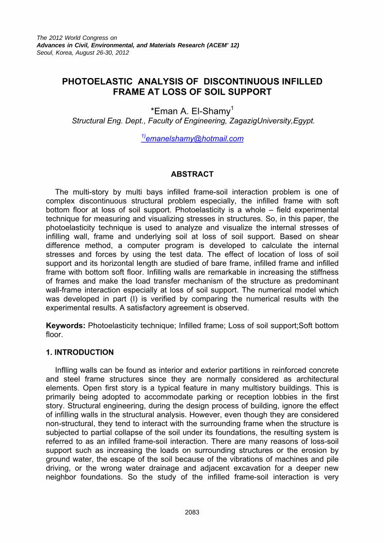
SOIL INTERACTION BEHAVIOR The photoelastic method utilizes the phenomenon of stress induced birefringence(14&15). The fringe order was determined by the placing the birefringent model in a polariscope as shown in photograph (1). The produced isochromatics can be classified to isoclinic lines and isochromatic frings. Isoclinic lines provide information on the direction of principle stresses throughout the model. Isochromatic frings provide the information on the constant difference of principle stresses. For each model a set of eight photoelastic digital photographs were obtained, two photographs for isochromatic lines (N) for dark and light fields respectively and six photographs for isoclinic line (θ) for the same model as shown in photographs (2-7). The value of (θ) varies from 0.0o to 90o. Based on the value of (N) and (θ) obtained from the test results at each point, the shear stress values may be determined by using the shear difference method according to the following equation (15,16,17):
θ=τ σ 2sint2
Nfxy
Where: N: is the fringe order number from isochromatic lines. fσ: is the fringe value for test material θ : is the angle of inclination of principle stress. From knowing the shear difference the normal stresses (σx and σy) can be obtained at any point. A computer program based on shear difference method was developed to solve and obtain the shear stress (τxy), the normal stresses (σx and σy) and the internal forces at each section in the model.
(a)Case(0)of infilled frame
(b)Case(1)of infilled frame Photograph (2): Ischromatic lines of different cases of infilled frame at b/B =0.
(a) Isochromatic line (N = 0.5, 1.5, 2.5, …)
(b) Isoclinic lines (θ = 45o)
Photograph (3): Isochromatic and isoclinic lines of case (1) of infill frame at b/B = 1.
(a) Isochromatic line (N = 0.5, 1.5, 2.5, …)
(b) Isoclinic lines (θ = 45o)
Photograph (4): Isochromatic and isoclinic lines of case (1) of infill frame at interior loss of support at b/B = 2.
(a) Isochromatic line (N = 0.5, 1.5, 2.5, …)
(b) Isoclinic lines (θ = 45o)
Photograph (5): Isochromatic and isoclinic lines of case (2) of infill frame at exterior loss of support at b/B = 1.
(a) Isochromatic line (N = 0.5, 1.5, 2.5, …)
(b) Isoclinic lines (θ = 45o)
Photograph (6): Isochromatic and isoclinic lines of case (2) of infill frame at interior loss of support at b/B = 2.
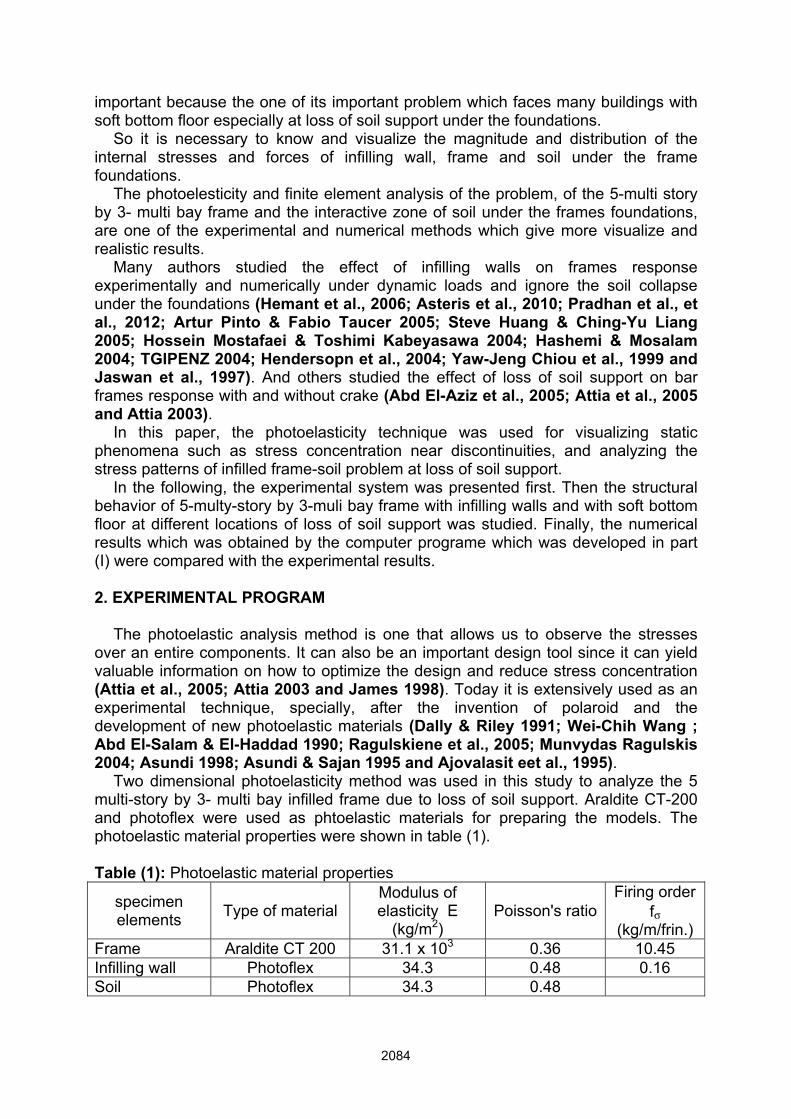
(a) bar frame at b/B = 0
(b) Case (1) of infilled frame at b/B = 0
(c) Case (2) of infilled frame at b/B = 0
(d) Case (1) of infilled frame at b/B = 0.5
(e) Case (2) of infilled frame at b/B = 0.5
(f) Case (1) of infilled frame at b/B = 1
(g) Case (2) of infilled frame at b/B = 1
Photographs (7): Isoclinic lines (θ = 0o,90o) of different cases of infilled frame at different cases of loss support . From the photographs (2-7), it is clear that the effect of infilling wall on frames at loss of soil support can be divided as follows: 1- The infilling walls are assessed to have a significant contribution on the response
and remain in the elastic range, where acting as wall-frame interaction which decrease the stress contour lines as the horizontal length – breadth ratios (b/B)
start to increase at different location of loss of soil support as shown in photographs (2b, 7b& 7d).
2- The infilling walls are assessed to have a significant contribution to the response which suffers significant stresses during the increase of escaping of soil support especially at exterior loss of soil support as shown in photographs (3&4). In this case the high probability of the formation of a soft bottom story was taken into account as shown in photographs (5&6).
A soft bottom story is affected on the stress contour lines distribution, which changes the distribution and increase the intensity as (b/B) ratios increase as shown in photographs (7). The distribution and value of the stresses on the soil are affected as (b/B) ratios increase, which localize changed and increase near the gap specially at exterior loss of soil support as shown in photographs (3a & 4a).
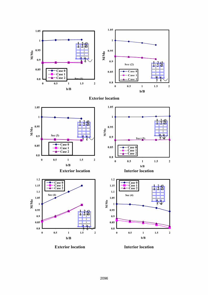
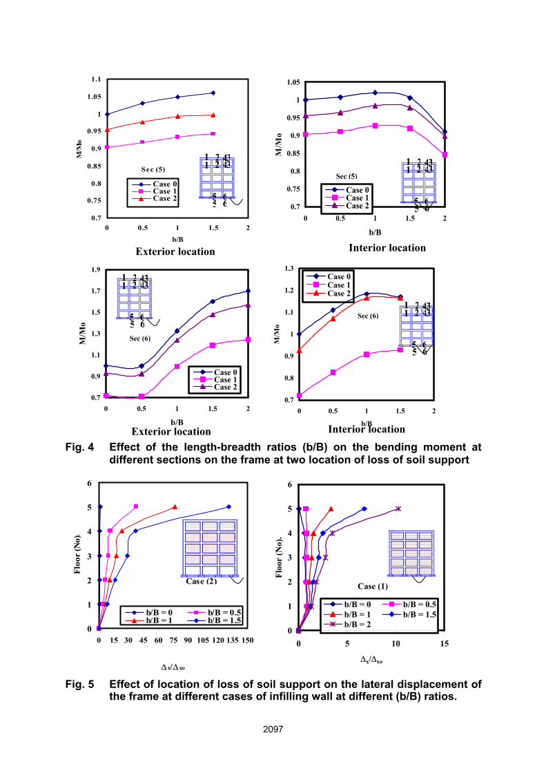
Photographs (7b, 7d & 7f) show the change of the stress contour lines intensity on the infilling walls especially near the interface between infilling walls and frame elements as (b/B) ratios increase, which decrease at corner over the loss of soil support and increase in the other corner due to relative movement between the infilling walls and frame elements. 3.1 Internal Forces, Stresses and Lateral Displacement The obtained results are plotted in figs (4-8) where the bending moment (M/Mo),lateral displacement (∆x/∆xo)and vertical normal stress(σy/σyo) were expressed in non-dimensional forms respectively, where( Mo, ∆xo and σyo are the bending moment, lateral displacement and vertical normal stresses of bare frame at no loss of soil support) were plotted with respect to horizontal length-breadth ratios (b/B) of loss of soil support at different cases of infilled frame at different locations of loss of soil support. It is clearly indicated that, the bending moment is affected by infilling walls which decreases to 30% at case (1) of infilled frame because of increasing the frame stiffness. However in case (2) of infilled frame, the bending moment decrease to 10% especially at sections near the loss of soil support due to decrease the frame stiffness at the soft bottom story. Also, the location of loss of soil support is affected on the redistribution and values of bending moment as (b/B) ratios increase which increase in its values up to 50% at sections near the location of loss of soil support especially at exterior location due to localize increasing in soil stresses as shown at sec. 6-6 in fig. (4). Figs. (5-8) show that the lateral displacement of the frame and normal stresses of infilling walls and soil are more affected by the locations of loss of soil support, where the lateral displacement increases in average 140% in case (2) of infilled frame at exterior location as (b/B) ratios increase due to increase the frame flexibility as shown in fig. (5). The normal stresses in infilling walls are more affected by the locations of loss of soil support especially over the location of loss of soil support, which increase up to 30 times of normal stresses than in case of no loss of soil support at exterior locations as shown in fig. (6). Moreover, the soft bottom story increase the infilling wall vertical normal stresses up to 25% as (b/B) ratios increase as shown in fig. (7). Fig. (8) indicates that, the average increase of soil normal stresses is 18% near the gap at exterior location as (b/B) ratios increase.
0.8
0.85
0.9
0.95
1
1.05
0 0.5 1 1.5 2
b/B
M/M
o
Case 0Case 1Case 2 Sec (1)
0.8
0.85
0.9
0.95
1
1.05
0 0.5 1 1.5 2
b/B
M/M
o
Case 0Case 1Case 2
Sec (2)
Exterior location
0.8
0.85
0.9
0.95
1
1.05
0 0.5 1 1.5 2
b/B
M/M
o
Case 0Case 1Case 2
Sec (3)
0.8
0.85
0.9
0.95
1
1.05
0 0.5 1 1.5 2b/B
M/M
o
Case 0Case 1Case 2
Sec (3)
Exterior location Interior location
0.8
0.85
0.9
0.95
1
1.05
1.1
1.15
1.2
0 0.5 1 1.5 2
b/B
M/M
o
Case 0Case 1Case 2
Sec (4)
0.8
0.85
0.9
0.95
1
1.05
1.1
1.15
1.2
0 0.5 1 1.5 2
b/B
M/M
o
Case 0Case 1Case 2
Sec (4)
Exterior location Interior location
11 2
2 4433
55
66 1
1 22 4
433
55
66
11 2
2 4433
55
66
11 2
2 4433
55
66
11 2
2 4433
55
66
11 2
2 4433
55
66
0.7
0.75
0.8
0.85
0.9
0.95
1
1.05
1.1
0 0.5 1 1.5 2b/B
M/M
o
Case 0Case 1Case 2
Sec (5)
0.7
0.75
0.8
0.85
0.9
0.95
1
1.05
0 0.5 1 1.5 2
b/B
M/M
o
Case 0Case 1Case 2
Sec (5)
0.7
0.9
1.1
1.3
1.5
1.7
1.9
0 0.5 1 1.5 2
b/B
M/M
o
Case 0Case 1Case 2
Sec (6)
0.7
0.8
0.9
1
1.1
1.2
1.3
0 0.5 1 1.5 2
b/B
M/M
oCase 0Case 1Case 2
Sec (6)
Fig. 4 Effect of the length-breadth ratios (b/B) on the bending moment at
different sections on the frame at two location of loss of soil support
0
1
2
3
4
5
6
0 15 30 45 60 75 90 105 120 135 150
∆x/∆xo
Floo
r (N
o).
b/B = 0 b/B = 0.5b/B = 1 b/B = 1.5
Case (2)
0
1
2
3
4
5
6
0 5 10 15
∆x/∆xo
Floo
r (N
o).
b/B = 0 b/B = 0.5b/B = 1 b/B = 1.5b/B = 2
Case (1)
Fig. 5 Effect of location of loss of soil support on the lateral displacement of
the frame at different cases of infilling wall at different (b/B) ratios.
11 2
2 4433
55
66
11 2
2 4433
55
66
11 2
2 4433
55
66
11 2
2 4433
55
66
Exterior location Interior location
Exterior location Interior location
-10-505
101520253035
0 0.1 0.2 0.3 0.4 0.5 0.6 0.7 0.8 0.9 1
X/LX
σ y/ σ
yo Exterior locationInterior location
Bay (1) Bay (2) Bay (3)
Fig. 6 Effect of location of loss of soil support on the infilling wall normal stresses at sec. A-A of bottom floor at b/B = 1.5.
-4
-3
-2
-1
0
1
2
0 0.1 0.2 0.3 0.4 0.5 0.6 0.7 0.8 0.9 1
X/LX
σ y/ σ
yo
Case 1Case 2
Bay (1) Bay (2) Bay (3)
Fig. 7 Effect of infilled frame on the infilling wall vertical normal stresses at sex. B-B of second floor at exterior location of loss of soil support at b/B = 1.5.
Fig. 8 Effect of length- breadth- ratios (b/B) on the soil vertical normal
stresses at different location of loss soil support.
A A
B B
Sec C
φ
node (1)
y,v ,λs
node (2)x,u ,
λn
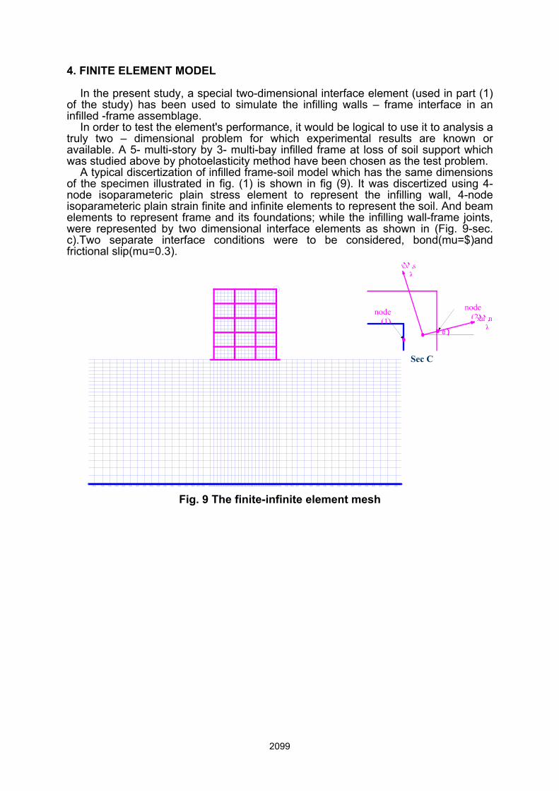
4. FINITE ELEMENT MODEL In the present study, a special two-dimensional interface element (used in part (1) of the study) has been used to simulate the infilling walls – frame interface in an infilled -frame assemblage. In order to test the element's performance, it would be logical to use it to analysis a truly two – dimensional problem for which experimental results are known or available. A 5- multi-story by 3- multi-bay infilled frame at loss of soil support which was studied above by photoelasticity method have been chosen as the test problem. A typical discertization of infilled frame-soil model which has the same dimensions of the specimen illustrated in fig. (1) is shown in fig (9). It was discertized using 4-node isoparameteric plain stress element to represent the infilling wall, 4-node isoparameteric plain strain finite and infinite elements to represent the soil. And beam elements to represent frame and its foundations; while the infilling wall-frame joints, were represented by two dimensional interface elements as shown in (Fig. 9-sec. c).Two separate interface conditions were to be considered, bond(mu=$)and frictional slip(mu=0.3).
Fig. 9 The finite-infinite element mesh
0
1
2
3
4
5
6
0 10 20 30 40 50 60 70 80 90
∆x/∆xo
Floo
r (N
o)
ExperimentalNumerical
0
1
2
3
4
5
6
0 10 20 30 40
∆x/∆xoFl
oor
(No)
Experimentalu = 0.3u = 00
a- Case 0 at exterior location at b/B = 1 b- Case 1 at exterior location at b/B =0.5
Fig. 9 Comparison between the experimental result and numerical result at
different cases of loss soil support and infilled frame at different b/B ratios.
4.1 Interface Behavior For the efficient non-linear analysis of infilling wall-frame at loss of soil support, it is necessary to consider relative frictional sliding, separation and rebounding of the interfaces. To account for this behavior, a special interface element has been presented in part (1) of the study. The non – linear behavior of the joints can therefore be treated by assigning the joint displacement and forces from the last load step in a step-by-step loading analysis procedure. 4.2 Results–Verification of the Model Lateral displacement of the infilled frame, obtained from the experimental results, are compared to the results obtained using the finite – infinite element model, which was developed in part(1) for two interface conditions as shown in fig. (9).In comparing the interface models, it is observed that the frictional slip condition (mu=0.3) provide a more reasonable representation of data than does the bonded assumption . Clearly, there is a good agreement between the results. 5. CONCLUSIONS The structural behaviors of the 5-multi-story by 3- multi-bay infilled frame with soft bottom floor at loss of soil support taking into consideration the soil-structure interaction are investigated experimentally by photoelasticity technique and numerically by using finite element method. Based on the shear difference method, the computer program has been developed. The numerical model which was
presented in part (1) is verified by comparing the numerical solution with the experimental results. A satisfactory agreement is obtained. According to the distribution of the principle stresses of the infilling wall in the infilled frame, it is found that, the infilling walls make the load transfer mechanism of the structure as predominate wall-frame interaction especially at loss of soil support. So, the equivalent strut cannot replace the infilling wall specially at loss of soil support. In addition, the infilling wall affects the behavior of the framed wall structure dominantly. The bottom soft story increases the flexibility of the frame and change the intensity of internal stresses of its elements near the location of loss of soil support .Moreover, increases the internal stresses of the upper infilling wall especially at exterior loss of soil support. On the other hand, the completely infilled wall increases the stiffness of the structure at different location of loss of soil support. The proposed numerical model is therefore proved to be capable of simulating the discontinuous behavior of the infilling wall-frame at loss of soil support. However, some important factors need further investigating. The non linear constitutive relations of brick and mortar are recommended to be considered. Furthermore, the bond slip of reinforcements is also highly recommended to be fully studied at loss of soil support in the future.
REFERENCES Abd El-Aziz and Sabry Fathy (2005), "Photoelastic analysis of cracked frames with loss of support" M.Sc.thesis, Str. Eng. Dept. Fac. of Eng. Zagazig University. Egypt. Abd El-Salam, S.S. and El-Haddad, M.H. (1990), "Photoelastic and theoretical analysis of cracked frames". International Journal of fracture, 45, 311-321. Ajovalasit, A., Barone, S. and Petrucci, G. (1995), "Towards rgb photoelasticity full-field automated photoelasticity in white light". Experimental mechanics, 35 (3), 193-200. Artur Pinto & Fabio Taucer (2005), "Assessment strengthening & Repair of full –scale Models of Existing RC frames" European laboratory for structural. Assessment (Elsa) EC, Joint Research center, IPSC, TP480K 120 Ispra (VA), Italy. Asteris, P.G., Kakaletsis, D.J., Chrysostomou, C.Z. and Smyrou, E.E. (2011), ”Failure Modes of In-filled Frames”,International Elec. Journal of Stru. Eng., 11(1). Asundi, A. (1998), "Recent Advances in Photoelastic Application". Advances and Applications, Singapore. Asundi, A. and Sajan, M.R. (1995), "Multiple led camera for dynamic photoelasticity". Applied optics, 34 (13), 2236-2240. Attia, G.A.M. (2003), "Experimental and numerical analysis of multi-story cracked frames with loss of support". Fourth Alexandria international conference of structural and geotechnical engineering, Alexandria University, Alexandria, Egypt. Vol 1, pp. 17-25 April. Attia, G.A.M., El Shamy, E.A. and Abd El Aziz, S.F. (2005), "Analysis of multi-story frame contains cracks at loss of soil support". Scientific Bulletin. Fac. Eng. Ain Shams Univ. vol. 40, No 4, December 31, Egypt. Dally, J.W., and W.F. Riley. (1991), "Experimental stress analysis". 3rd ed. New York; McGraw – Hill. Hashemi, A. and Mosalam, K.M. (2004), "Transient Analysis of Reinforced concrete frame with and without Masonary infill wall under blast". Emirates Journal for engineering research, 9 (2), 97-103.