Dr. Ron Licht 18A - 1 www.structuredindependentlearning.com Physics 30 Lesson 18A Electric Circuits I. Circuit symbols The various paths from source to load and back may be extremely complicated and may contain many different types of electrical devices and connectors. Circuit diagrams or schematic diagrams are drawn using the following symbols to show exactly how each device is connected to other devices. The components of an electric circuit are called elements and their symbols are displayed below. AC generator battery, power supply resistor variable resistor (rheostat) lamp (resistor) closed switch open switch fuse (A fuse is a device that melts when the current in a circuit goes above a designed level. The melting fuse breaks the circuit.) ground ammeter voltmeter
Transcript
Dr. Ron Licht 18A - 1 www.structuredindependentlearning.com
Physics 30 Lesson 18A Electric Circuits
I. Circuit symbols
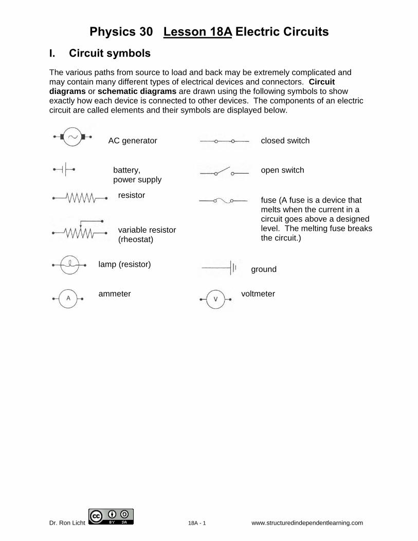
The various paths from source to load and back may be extremely complicated and may contain many different types of electrical devices and connectors. Circuit diagrams or schematic diagrams are drawn using the following symbols to show exactly how each device is connected to other devices. The components of an electric circuit are called elements and their symbols are displayed below.
AC generator
battery, power supply
resistor
variable resistor (rheostat)
lamp (resistor)
closed switch
open switch
fuse (A fuse is a device that melts when the current in a circuit goes above a designed level. The melting fuse breaks the circuit.)
ground
ammeter voltmeter
Dr. Ron Licht 18A - 2 www.structuredindependentlearning.com
II. Kirchhoff's rules
When components are connected together to create circuits they may be connected in two different ways; in series or in parallel. When components are in series, current flows consecutively through those components. When connected in parallel, current flows concurrently through the components. As electrons move through a circuit, they lose energy in the various loads they pass through, and they often have to part company and go different ways when they reach a junction of more than two wires. Two basic questions about how electric circuits operate are: When electrons have several loads to pass through, what governs the amount of
electric potential energy they will lose in each load? When electrons have a choice of several possible paths to follow, what governs the
number of electrons that will take each path? An understanding of the operation of simple series and parallel circuits depends on the answers to these questions. Gustav Robert Kirchhoff (1824-1887), a German physicist, proposed two “rules” that are used to analyse electric circuits. These rules are simply the logical consequences that arise in circuits as a result of conservation laws. 1. The current rule (or point rule) states that the total current reaching any point in a
circuit is equal to the total current leaving that point. (This is a consequence of the Law of Conservation of Charge.)
2. The voltage rule (or loop rule) states that the total change in potential around any closed loop in a circuit is equal to zero. (This is a consequence of the Law of Conservation of Energy.)
series circuit parallel circuit
Dr. Ron Licht 18A - 3 www.structuredindependentlearning.com
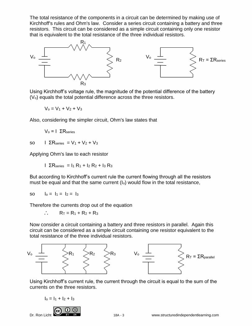
The total resistance of the components in a circuit can be determined by making use of Kirchhoff's rules and Ohm's law. Consider a series circuit containing a battery and three resistors. This circuit can be considered as a simple circuit containing only one resistor that is equivalent to the total resistance of the three individual resistors. Using Kirchhoff’s voltage rule, the magnitude of the potential difference of the battery (Vo) equals the total potential difference across the three resistors.
Vo = V1 + V2 + V3 Also, considering the simpler circuit, Ohm's law states that Vo = I ΣRseries
so I ΣRseries = V1 + V2 + V3 Applying Ohm's law to each resistor I ΣRseries = I1 R1 + I2 R2 + I3 R3 But according to Kirchhoff’s current rule the current flowing through all the resistors must be equal and that the same current (Io) would flow in the total resistance, so Io = I1 = I2 = I3 Therefore the currents drop out of the equation
RT = R1 + R2 + R3
Now consider a circuit containing a battery and three resistors in parallel. Again this circuit can be considered as a simple circuit containing one resistor equivalent to the total resistance of the three individual resistors. Using Kirchhoff’s current rule, the current through the circuit is equal to the sum of the currents on the three resistors. Io = I1 + I2 + I3
R1
R3
R2 Vo
RT = ΣRseries Vo
R1 R2 R3 Vo
RT = ΣRparallel Vo
Dr. Ron Licht 18A - 4 www.structuredindependentlearning.com
This is the same current that flows through the simpler circuit. Applying Ohm's law to the simpler circuit
parallel
oo
R
VI
so 321
parallel
o IIIR
V
Applying Ohm's law to the currents on the individual resistors
3
3
2
2
1
1
parallel
o
R
V
R
V
R
V
R
V
But applying Kirchhoff’s voltage rule, all these potential differences are equal, so they drop out of the equation.
321T R
1
R
1
R
1
R
1
III. Electric circuits – summary of rules
The rules for a series circuit are: 1. The current is the same through each resistor:
Io = I1 = I2 = I3
2. The potential difference (drop) across each resistor is different. However, all of the potential differences add up to the original voltage (Vo):
Vo V1 V2 V3 Vo = V1 + V2 + V3
3. The total resistance is calculated using:
RT = R1 + R2 + R3
The rules for a parallel circuit are: 1. The current is different through each resistor, but they add up to the total current
(Io):
Io I1 I2 I3 Io = I1 + I2 + I3
2. The potential difference (drop) across each resistor is the same.
Vo = V1 = V2 = V3
3. The total resistance is calculated using:
321T R
1
R
1
R
1
R
1
R1
R2
I1
I2
Io Io
Dr. Ron Licht 18A - 5 www.structuredindependentlearning.com
Example 1
You are given three resistors:
A 20
B 30
C 50 What is the total resistance if they are connected: a) in series? b) in parallel? c) A and B are in parallel which are then in series with C
RT = 1 = 9.68 0.0103 c) first we calculate the resistance of the parallel resistors (RA)
1 = 1 + 1 = 1 + 1 = 0.08333 RA = 1/0.0833 = 12
RA R1 R2 20 30 now we can add the parallel part with resistor C in series
RT = 12 + 50 62
Dr. Ron Licht 18A - 6 www.structuredindependentlearning.com
IV. Electric circuit analysis
To solve problems concerning different kinds and combinations of circuits, we apply the rules for series and parallel circuits given above. The main thing to do is to take advantage of those things that are constant for a circuit:
For series circuits, the current is the same throughout.
For parallel elements, the voltage is the same for each resistor.
Example 2
For the given circuit, what is the current and potential drop across each resistor? For a series circuit the current in each resistor is the same as the total current (Io). Therefore, if we find Io, we know I1, I2, and I3.
Io = Vo = 50 V = 0.333 A I1 = I2 = I3 = Io = 0.333 A
RT 150
V1 = I1 R1 = 0.333 A (40 ) = 13.3 V
V2 = I2 R2 = 0.333 A (20 ) = 6.67 V
V3 = I3 R3 = 0.333 A (90 ) = 30.0 V
As a check: V1 + V2 + V3 = 13.3 V + 6.67 V + 30.0 V =50 V (expected value)
RT = R1 + R2 + R3 = 40 20 90 150
R1 = 40
R3 = 90
R2 = 20 50 V
Dr. Ron Licht 18A - 7 www.structuredindependentlearning.com
For the given circuit, what is the current and potential drop across each resistor? What is the current at the power supply (Io)? For a parallel circuit the potential difference is the same for each resistor.
V1 = V2 = V3 = Vo = 30 V I1 = V1 = 30 V = 3.0 A
R1 10 I2 = V2 = 30 V = 6.0 A
R2 5 I3 = V3 = 30 V = 2.0 A
R3 15 Io = I1 + I2 + I3 = 3.0 A + 6.0 A + 2.0 A = 11.0 A
Example 4
For the given circuit, what is the current and potential drop across each resistor? What is the current at the power supply (Io)? This circuit contains both a parallel part (R1 is parallel to R2 + R3) and a series part (R2 and R3 are in series). If we think of R2 + R3 as one resistor RA, we know that the potential drop across R1 and RA is 10 V.
V1 = VA = 10 V I1 = V1 / R1 = 10 V / 10 = 1.0 A Since R2 and R3 are in series, the current will be the same in both and will be IA. IA = VA = 10 V = 0.50 A Io = I1 + IA = 1.0 A + 0.50 A = 1.5 A
RA 15 + 5
V2 = I2 R2 = 0.50 A (15 ) = 7.5 V
V3 = I3 R3 = 0.50 A (5 ) = 2.5 V
10 5 15 30 V
10
15
5 10 V
Dr. Ron Licht 18A - 8 www.structuredindependentlearning.com
V. Measuring current and potential difference
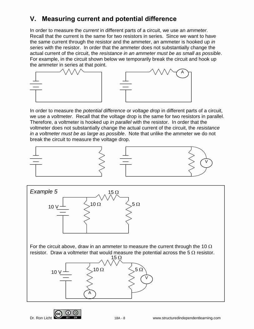
In order to measure the current in different parts of a circuit, we use an ammeter. Recall that the current is the same for two resistors in series. Since we want to have the same current through the resistor and the ammeter, an ammeter is hooked up in series with the resistor. In order that the ammeter does not substantially change the actual current of the circuit, the resistance in an ammeter must be as small as possible. For example, in the circuit shown below we temporarily break the circuit and hook up the ammeter in series at that point. In order to measure the potential difference or voltage drop in different parts of a circuit, we use a voltmeter. Recall that the voltage drop is the same for two resistors in parallel. Therefore, a voltmeter is hooked up in parallel with the resistor. In order that the voltmeter does not substantially change the actual current of the circuit, the resistance in a voltmeter must be as large as possible. Note that unlike the ammeter we do not break the circuit to measure the voltage drop.
Example 5
For the circuit above, draw in an ammeter to measure the current through the 10
resistor. Draw a voltmeter that would measure the potential across the 5 resistor.
A
V
A
10
15
5 10 V
V
10
15
5 10 V
Dr. Ron Licht 18A - 9 www.structuredindependentlearning.com
VI. Practice problems
1. Three resistors 20 , 10 and 5 are to be connected in a circuit with a 20 V power supply. For each configuration below:
Draw the circuit.
Calculate the total resistance.
For each circuit, calculate the current and the potential difference across each resistor.
A. all in series B. all in parallel
C. The 10 and 20are parallel and in series with the 5 resistor.
Dr. Ron Licht 18A - 10 www.structuredindependentlearning.com
VII. Hand-in assignment
1. A string of 8 Christmas tree lights connected in series to a 120 V source draws a current of 0.75 A. Find:
a) the total resistance of the string of lights (160
b) the resistance of each light (20 c) the potential difference across each light (15 V)
2.
a) What is the resistance of a toaster that draws a current of 6.0 A from a 120
V source? (20 b) What resistance would have to be added in a series with the same toaster
to reduce it’s current to 4.0 A? (10 3. Calculate the total resistance in each of these cases:
a) 10 30 , and 50 in a series (90
b) 6 5 , and 30 in a parallel (2.5
c) 9 in a series with a combination consisting of 4 , and 12 connected in
parallel with each other. (12
4. How many 160 resistors must be connected in parallel to draw a current of 6.0 A from a 120 V source? (8)
5. The potential difference across a heating coil is 6.0 V when the current through it
is 3.0 A. What resistance must be added in series with the coil to reduce the
current through it to 2.0 A? (1.0 6. A portable radio is designed to operate at a potential difference of 6.0 V and a
current of 250 mA, but the only source available has a potential of 10.0 V. What resistance must be added in series with the radio to make it operate properly?
(16 7. Examine these circuits and find the values indicated.
a) Find: R2, R2, and V3.
b) Find: V0, R1, and Rtotal.
Dr. Ron Licht 18A - 11 www.structuredindependentlearning.com
c) Find: R3, I1, I2, I4, I5, and I6.
d) Find: I1, R1, and R2.
e) I0, I1, I2, I3, I4, V1, V2, V3, and V4.
a) (10 12 , 4.8 V
b) (36 V, 18 6
c) (4 , 1 A, 5 A, 3.3 A, 1.6 A, 1.1 A
d) (3.0 A, 2.0 6.0
e) (1.5 A, 1.5 A, 0.30 A, 0.90 A, 0.30 A, 4.2 V, 1.8 V, 1.8 V, 1.8 V 8. For the combination of resistors shown in the drawings below, determine the
equivalent resistance between points A and B. (100 6.76
i ii
Dr. Ron Licht 18A - 12 www.structuredindependentlearning.com
9. The current in the 8.00 resistor in the drawing is
0.500 A. Find the current in the 20.0 resistor and
in the 9.00 resistor. (0.750 A, 2.10 A) 10. Find the current across each resistor in the circuit in
the diagram. (2.0 A, 1.0 A, 1.0 A)
11. Two batteries, each with an internal resistance of 0.015 , are connected as shown in the diagram. In effect, the 9.0 V battery is being used to charge the 8.0 V battery . What is the current in the circuit? (33.3 A)
12. What would be the current in the circuit above if the 8.0 V battery was turned
around and reconnected? (567 A) 13. In the circuit below X, Y and Z are switches. Describe which lights are on and
which lights are off in the following situations. A. X open, Y closed, Z closed B. X closed, Y open, Z closed C. X closed, Y open, Z open D. X closed, Y closed, Z closed
Dr. Ron Licht 18A - 13 www.structuredindependentlearning.com
Circuit Analysis Activity
Series Circuits
Problem: What is the relationship between electric potential and electric current in series circuits?
Materials:
low-voltage DC power supply (set at the maximum setting)
two resistors (130 , 220 ) DC ammeter DC voltmeter various connecting wires
Procedure: 1. Use the value on the block for each resistor in your calculations. 2. Set up the series circuit shown in the diagram. 3. Set and measure the voltage (Vo) from the power supply to 7.0 V. 4. Before proceeding with other measurements, calculate RT, Io, I1, I2, V1 and V2.
Show all calculations. 5. Using the appropriate meters, measure the values of Io, I1, I2, V1 and V2 in the
circuit.
Questions: 1. How many different paths are there for an electron to take through a series circuit?
Explain. 2. Utilizing an appropriate table of results, comment on how the measured and
calculated values compare. 3. If the resistors were rearranged in this circuit, how would the total resistance,
potential drop and current values change?
R1 (130 )
R2 (220 )
Vo
Dr. Ron Licht 18A - 14 www.structuredindependentlearning.com
Parallel Circuits
Problem: What is the relationship between electric potential and electric current in parallel circuits?
Procedure: 1. Using the same resistors and power supply from the series circuit activity, set up
the parallel circuit shown in the diagram. 3. Set and measure the voltage (Vo) from the power supply to 7.0 V. 4. Before proceeding with other measurements, calculate RT, Io, I1, I2, V1 and V2.
Show all calculations. 5. Using the appropriate meters, measure the values of Io, I1, I2, V1 and V2 in the
circuit.
Questions: 1. How many different paths are there for an electron to take through a parallel
circuit? Explain. 2. Utilizing an appropriate table of results, comment on how the measured and
calculated values compare. 3. If the resistors were rearranged in this circuit, how would the total resistance,
potential drop and current values change?
R1 R2 Vo
Dr. Ron Licht 18A - 15 www.structuredindependentlearning.com
Combination Circuit
Problem: What is the relationship between electric potential and electric current in combination circuits?
Procedure: 1. Set up the circuit shown in the diagram. (For this set up you require another 130
resistor.) 3. Set and measure the voltage (Vo) from the power supply to 7.0 V. 4. Before proceeding with other measurements, calculate RT, Io, I1, I2, I3, V1, V2, and
V3. Show all calculations. 5. Using the appropriate meters, measure the values of Io, I1, I2, I3, V1 , V2, and V3in
the circuit.
Questions: 1. How many different paths are there for an electron to take through a combination
circuit? Explain. 2. Utilizing an appropriate table of results, comment on how the measured and
calculated values compare. 3. If the resistors were rearranged in this circuit, how would the total resistance,