+ All Categories
Home > Documents > PI VOLTAGE CONTROL TECHNIQUE FOR 3 PHASE … filemenggunakan pengawal adalah reka bentuk menggunakan...

PI VOLTAGE CONTROL TECHNIQUE FOR 3 PHASE … filemenggunakan pengawal adalah reka bentuk menggunakan...

Date post: 30-May-2019
Category:
Upload: vutram
View: 215 times
Download: 0 times
Share this document with a friend
37
PI VOLTAGE CONTROL TECHNIQUE FOR 3 PHASE INDUUCTION MOTOR USING SIMULINK AND ARDUINO WAN AHMAD KHUSAIRI BIN WAN CHEK A project report submitted in partial fulfillment of the requirement for the award of the Degree of Master of Electrical Engineering Faculty of Electrical and Electronics Engineering UniversitiTun Hussein Onn Malaysia JANUARY 2014
Transcript

PI VOLTAGE CONTROL TECHNIQUE FOR 3 PHASE INDUUCTION

MOTOR USING SIMULINK AND ARDUINO

WAN AHMAD KHUSAIRI BIN WAN CHEK

A project report submitted in partial

fulfillment of the requirement for the award of the

Degree of Master of Electrical Engineering

Faculty of Electrical and Electronics Engineering

UniversitiTun Hussein Onn Malaysia

JANUARY 2014

iv

ABSTRACT

Induction motor is the most used in industry because of its high robustness, reliability,

low cost, high efficiency and good self starting capability. However is also has its own

limitation which can be divided into three categories which is nonlinearity, complex

computation and uncertainty system. The development of this project is to control the 3

phase induction motor by using Arduino Uno controller and also using Simulink in

MATLAB. Arduino Uno also is a part from series of controller where it is connected to

the PWM inverter and also connected to motor driver as to turn the 3 phase induction

motor on. Voltage sensor is used as to detect any changes that are supplied from the

motor driver to the induction motor as to ensure that the voltage that is supplied to a

constant voltage value to the induction motor. This method is known as voltage control.

The measured voltage is then compared with the desired reference voltage. The error

that is produced is than corrected as to minimize the existing error by using a controller

is design using Simulink in Matlab and than is interfaced into the Arduino Uno. Arduino

Uno will create PWM signal that is sent to the PWM inverter as to improve the

induction motor performance. Based on the result obtain shows that the error from

reference voltage and measured voltage is minimized and the PWM that is produced also

has differences in term of width.

v

ABSTRAK

Motor aruhan adalah yang paling banyak digunakan dalam industri kerana keteguhan

tinggi, kebolehpercayaan , kos rendah , kecekapan tinggi dan keupayaan permulaan diri

yang baik. Walau bagaimanapun juga mempunyai had tersendiri yang boleh dibahagikan

kepada tiga kategori iaitu ketaklelurusan , pengiraan kompleks dan sistem yang tidak

menentu. Pembangunan projek ini adalah untuk mengawal motor aruhan 3 fasa dengan

menggunakan Arduino Uno pengawal dan juga menggunakan Simulink dalam

MATLAB. Arduino Uno juga adalah sebahagian dari siri pengawal di mana ia

disambungkan ke penyongsang PWM dan juga disambungkan kepada pemandu motor

untuk menghidupkan motor aruhan 3 fasa. Sensor voltan digunakan untuk mengesan

apa-apa perubahan yang dibekalkan dari pemandu motor kepada motor induksi bagi

memastikan voltan yang dibekalkan kepada nilai voltan tetap untuk motor aruhan.

Kaedah ini dikenali sebagai kawalan voltan. Voltan yang diperolehi kemudiannya

dibandingkan dengan voltan rujukan yang dikehendaki. Kesilapan yang dihasilkan

adalah daripada diperbetulkan untuk meminimumkan ralat yang sedia ada dengan

menggunakan pengawal adalah reka bentuk menggunakan Simulink dalam Matlab dan

daripada yang diantaramukakan ke Arduino Uno. Arduino Uno akan mewujudkan

isyarat “PWM” yang dihantar kepada penyongsang “PWM” untuk meningkatkan

prestasi motor induksi. Berdasarkan kepada keputusan mendapatkan menunjukkan

bahawa kesilapan itu daripada voltan rujukan dan voltan yang diukur dikurangkan dan

“PWM” yang dihasilkan juga mempunyai perbezaan dari aspek lebar.

vi

TABLE OF CONTENTS

TITLE i

DECLARATION ii

ACKNOWLEDGEMENTS iii

ABSTRACT iv

TABLE OF CONTENTS vi

LIST OF TABLES ix

LIST OF FIGURES x

LIST OF SYMBOLS AND ABBREVIATIONS xii

CHAPTER 1 INTRODUCTION 1

1.1 Project Background 1

1.2 Problem Statement 2

1.3 Objective 3

1.4 Scope 3

CHAPTER 2 LITERATURE REVIEW 4

2.1 Motor 4

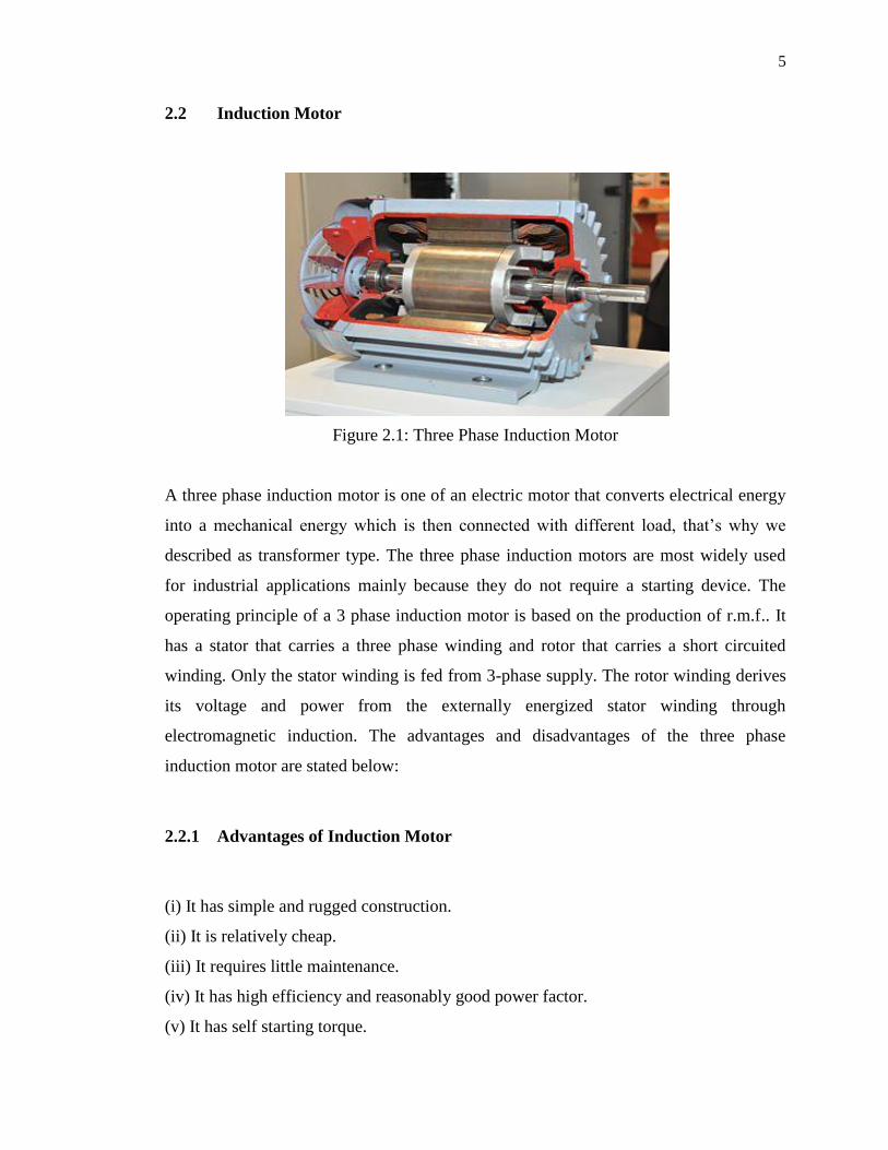
2.2 Induction Motor 5

2.2.1 Advantages Of Induction Motor 5

2.2.2 Disadvantages Of Induction Motor 6

2.3 Inverter 6

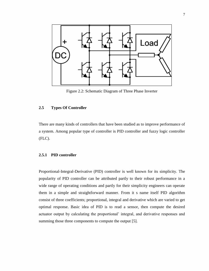
2.4 Three- Phase Inverter 6

2.5 Types Of Controller 7

2.5.1 PID Controller 7

vii

2.5.2 Fuzzy Logic Controller 9

2.6 Arduino Uno 11

CHAPTER 3 METHODOLOGY 14

3.1 Block Diagram Of the Project 14

3.2 The Project Flowchart 15

3.3 Arduino Io Library 16

3.4 Inverter Design 17

3.4.1 Part List For Inverter 17

3.5 Gate Driver Design 18

3.5.1 Part List For Gate Driver Design 19

3.6 Proposed Controller 20

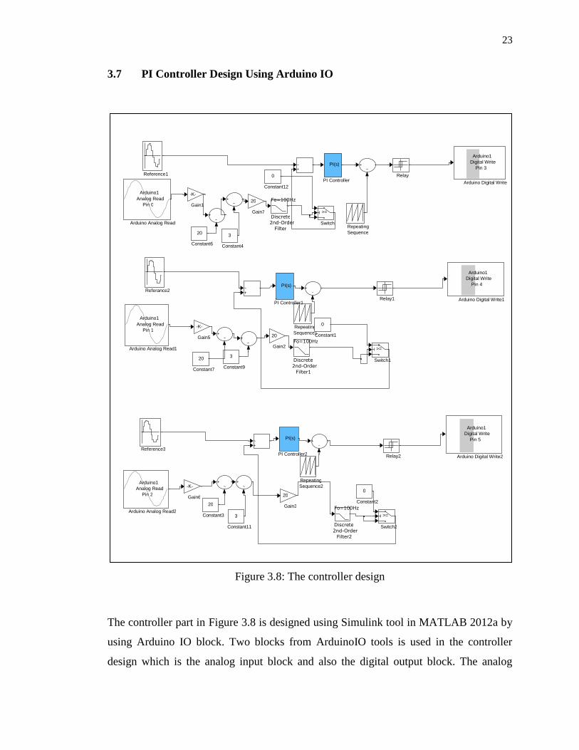
3.7 PI Controller Design Using Arduino IO 23

3.8 Digital To Analog Converter (DAC) 25

3.9 PWM Technique 25

3.10 Voltage Divider Circuit 27

CHAPTER 4 RESULT AND DISCUSSION 28

4.1 Open Loop Control Analysis 28

4.2 Simulation Of Open Loop System 29

4.3 Experimental Result 30

4.4 Closed Loop Control Analysis 32

4.5 Simulation On Closed Loop System 33

4.6 Experimental Result 35

4.7 Voltage Sensor (Voltage Divider Circuit) 37

CHAPTER 5 CONCLUSION AND RECOMMENDATION 39

5.1 Conclusion 39

5.2 Recommendation 40

5.3 Future Works 40

viii

REFERENCES 41

ix

LIST OF TABLES

2.1 Arduino Uno specifications 12

3.1 Component for inverter design 17

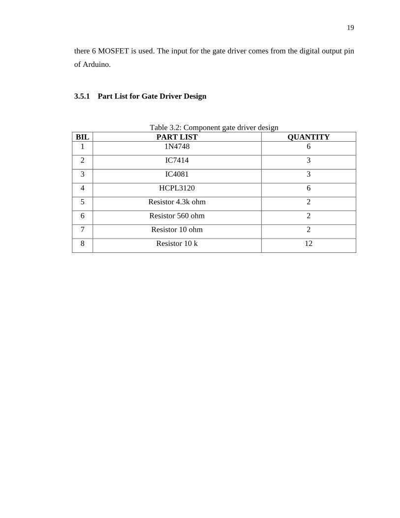
3.2 Component gate driver design 19

x

LIST OF FIGURES

2.1 Three Phase Induction Motor 5

2.2 Schematic Diagram of Three Phase Inverter 7

2.3 Arduino Uno Board 11

3.1 Project block diagram 14

3.2 Project flowchart 15

3.3 Arduino IO Simulink Library 16

3.4 six level 3 phase inverter design 17

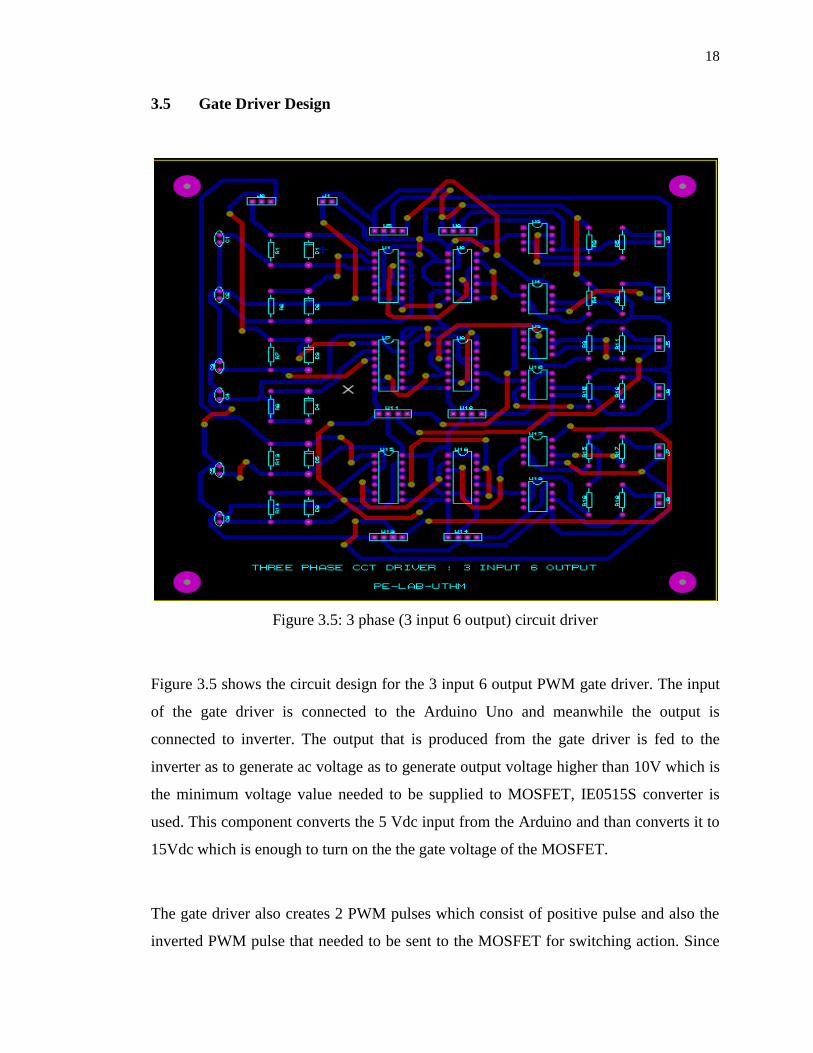
3.5 3 phase (3 input 6 output) circuit driver 18

3.6 The Proposed Controller 20

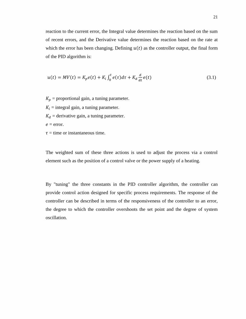
3.7 PID controller system 22

3.8 The controller design 23

3.9 PI controller setting 24

3.10 Digital to analog converter 25

3.11 2 levels comparison signal graph 26

3.12 PWM output 26

3.13 Voltage divider as voltage sensor 27

4.1 Open loop system 28

4.2 Reference signal and sampled signal waveform 29

4.3 PWM for open loop 30

4.4 Gate driver PWM 30

4.5 Line to line voltage 31

4.6 Line current for the open loop 31

4.7 Closed loop PI controller design 32

4.8 Simulation on error 33

4.9 normalized error from PI controller 34

xi

4.10 Simulation on generated PWM signal 34

4.11 PWM at inverter input 35

4.12 line to line voltage 36

4.13 closed loop line current 36

4.14 output from PI controller 37

4.15 output from the transformer 37

4.16 shifted ac signal waveform 38

xii

LIST OF SYMBOLS AND ABBREVIATIONS

PWM - Pulse Width Modulation

PIC - Peripheral Interface Controller

HP - Horse Power

IM - Induction Motor

FLC - Fuzzy Logic Controller

CM - Common Mode

AC - Alternating Current

DC - Direct Current

PID - Proportional – Integral - Derivative

PI - Proportional – Integral

e.m.f - Electromagnetic Field

r.m.f - Rotating Magnetic Field

AR - Auto Regressive

MA - Moving Average

PEF - prediction error filter

DTC - Direct Torque Control

ANN - Artificial Neural Network

Vgs Gate Voltage

IO - Input Output

Kp - Proportional gain

KI - Integral gain

MOSFET - Metal–Oxide–Semiconductor Field-Effect

Transistor

LC - Inductor - Capacitor

1

INTRODUCTION

1.1 Project Background

Since its invention, the three phase induction motor (IM) has been widely used in

industry because of its simple construction and low maintenance machine. Although

three phase induction motor is widely used, it also has its limitations such as the motor

speed decreases as the load increases, low starting torque and high starting current. To

increase the efficiency and performance of induction motor, controller system has been

developed. There are two types of controller system which is adaptive and passive

controller. The fuzzy logic controller (FLC) and the Proportional – Integral – Derivative

(PID) controller are examples for adaptive controller and meanwhile relay, sliding mode

control and hysteresis are examples for passive controller. Three phase induction motor

has variable speed and the best way to control the speed of induction motor drives using

converter – inverter system [1]. It is known that by using inverter to generate three phase

AC supply from a single DC source it introduces common mode (CM) voltage at the

stator star point of the IM with respect to the ground[1]. To control the three phase

inverter is by injecting pulse width modulation (PWM) signal from any existing

microcontroller that exists in the market. For an example PIC, Arduino, Altera board are

examples of PWM generating devices that can be used to control the inverter as to

increase the performance of a three phase induction motor. Arduino DSP controller has

been chosen because Arduino provides platform that helps users to understand the

workflow for designing an embedded system without using manual programming. By

using Simulink in Matlab user able to create algorithms for their desired control system

by just using the block that exists in the library as to create or design their own control

system.

2

1.2 Problem Statement

Nowadays three phase induction motor is a common device in industries. It works on the

principle of induction where electro-magnetic field (emf) that is induced in to the rotor

conductors when rotating magnetic field of stator cuts the stationary rotor conductors.

Induction motors are characterized by highly non-linear, complex and time-varying

dynamics and inaccessibility of some of the states and outputs for measurements, and

hence it can be considered as a challenging engineering problem [2].Three phase

induction motor were ideally used because of its simple construction and free

maintenance. Not only that since the induction motor has no brushes and easy to control,

many older DC motors are being replaced with induction motors and accompanying

inverters in industrial applications. In induction motor problems still exist in an

induction motor such as improper voltage value, motor has inadequate torque to drive

the load, overload or can be instantaneous trip. Low voltage is normally not the direct

cause of motor overheating since the overload relays will turn the motor off line when

the current exceeds rated amps. As a result, the motor will not generate rated HP. The

motor slip also increases proportionally to the square of the voltage drop resulting, the

motor will be running slower with a lower output and the process would not be

producing as expected [3]. The need of variable frequency machine parameter variations

and the difficulties of processing feedback signals in the presence of harmonic create the

complexity [4]. It was difficult to vary the frequency to the motor and therefore make

the uses for the induction motor were limited. To control the speed of a motor and as

well other parameter normally uses a power electronic device which is known as an

inverter. A typical unit will take the mains AC supply, rectify and smooth it into a "link"

DC voltage, and, then convert it into the desired AC waveform. In general, a DC-to-AC

converter is called an inverter, which is probably where the motor-control inverter gets

its name. But in order to control the switching of power transistor in the inverter, we

need to supply PWM signal to the power transistor. To generate this PWM signal,

normally microcontroller is used as to create the switching sequence to the power

transistor.

3

1.3 Objective

The objectives of this project are listed as follows:

1.3.1 To learn and develop PWM using PI controller for induction motor.

1.3.2 To control the induction motor using voltage source controller method.

1.3.3 To interface the Arduino Uno controller with MATLAB

1.4 Scope

In this project the scope of work:

1.4.1 To develop PI controller using Simulink in Matlab.

1.4.2 To develop voltage controller method for induction motor.

1.4.3 To develop the PWM inverter and 3 phase motor driver.

1.4.4 Interfacing the Simulink in Matlab with Arduino IO.

4

CHAPTER 2

LITERATURE REVIEW

2.1 Electric Motor

Motor mostly found in applications as diverse as industrial fans, blowers and pumps,

machine tools, household appliances, power tools, and disk drives. Electric motors can

be powered by direct current (DC) sources, such as from batteries, motor vehicles or

rectifiers, or by alternating current (AC) sources, such as from the power grid, inverters

or generators. Small motors may be found in electric watches. General-purpose motors

with highly standardized dimensions and characteristics provide convenient mechanical

power for industrial use. The largest of electric motors are used for ship propulsion,

pipeline compression and pumped-storage applications with ratings approaching a

megawatt. Electric motors may be classified by electric power source type, internal

construction, application, type of motion output, and so on.

5

2.2 Induction Motor

Figure 2.1: Three Phase Induction Motor

A three phase induction motor is one of an electric motor that converts electrical energy

into a mechanical energy which is then connected with different load, that’s why we

described as transformer type. The three phase induction motors are most widely used

for industrial applications mainly because they do not require a starting device. The

operating principle of a 3 phase induction motor is based on the production of r.m.f.. It

has a stator that carries a three phase winding and rotor that carries a short circuited

winding. Only the stator winding is fed from 3-phase supply. The rotor winding derives

its voltage and power from the externally energized stator winding through

electromagnetic induction. The advantages and disadvantages of the three phase

induction motor are stated below:

2.2.1 Advantages of Induction Motor

(i) It has simple and rugged construction.

(ii) It is relatively cheap.

(iii) It requires little maintenance.

(iv) It has high efficiency and reasonably good power factor.

(v) It has self starting torque.

6

2.2.2 Disadvantages of Induction Motor

(i) It is essentially a constant speed motor and its speed cannot be changed easily.

(ii) Its starting torque is inferior to dc shunt motor.

2.3 Inverter

An inverter is an electrical device that converts direct current (DC) to alternating current

(AC); the resulting AC can be at any required voltage and frequency with the use of

appropriate transformers, switching, and control circuits Static inverters have no moving

parts and are used in a wide range of applications, from small switching power supplies

in computers, to large electric utility high-voltage direct current applications that

transport bulk power. Inverters are commonly used to supply AC power from DC

sources such as solar panels or batteries.

2.4 Three- Phase Inverter

A basic three-phase inverter consists of three single-phase inverter switches each

connected to one of the three load terminals. For the most basic control scheme, the

operation of the three switches is coordinated so that one switch operates at each 60

degree point of the fundamental output waveform. This creates a line-to-line output

waveform that has six steps. The six-step waveform has a zero-voltage step between the

positive and negative sections of the square-wave such that the harmonics that are

multiples of three are eliminated as described above. When carrier-based PWM

techniques are applied to six-step waveforms, the basic overall shape, or envelope, of the

waveform is retained so that the 3rd harmonic and its multiples are cancelled.

7

Figure 2.2: Schematic Diagram of Three Phase Inverter

2.5 Types Of Controller

There are many kinds of controllers that have been studied as to improve performance of

a system. Among popular type of controller is PID controller and fuzzy logic controller

(FLC).

2.5.1 PID controller

Proportional-Integral-Derivative (PID) controller is well known for its simplicity. The

popularity of PID controller can be attributed partly to their robust performance in a

wide range of operating conditions and partly for their simplicity engineers can operate

them in a simple and straightforward manner. From it s name itself PID algorithm

consist of three coefficients; proportional, integral and derivative which are varied to get

optimal response. Basic idea of PID is to read a sensor, then compute the desired

actuator output by calculating the proportional’ integral, and derivative responses and

summing those three components to compute the output [5].

8

A comparison paper [4] based on speed control of induction motor using PI controller

and PID controller. And from their finding they come with a conclusion that PID

controller gives better speed response in terms of settling time, rise time and steady state

error.

A study [6] on a predictive PID controller for DC-DC converters using an adaptive

prediction error filter (PEF) in the controller feedback loop has been presented. They use

specific mathematical analysis such as Auto Regressive (AR) process generator and

Moving Average (MA). They come out with a result that their controller has superior

performance over a classical PID approach in terms of system disturbance rejection,

improved stability and output regulation.

A paper [7] on controlling ac servo motor using neural network PID controller stated

that in the industry, the PI or PID controller is widely used by means of servo system

control. These controllers enable excellent ability if a simple control algorithm be

implemented.

A paper [8] titled Design of Robust PID Controller With Disturbance Rejection For

Motor Using Immune Algorithm stated that A Proportional – Integral – Derivative (PID)

controller has been widely used in the most industrial processes despite continual

advances in control theory. This is not only due to the simple structure which is

theoretically easy to understand but also to the fact that the tuning technique provides

adequate performance in the vast majority of applications.

This paper [9] presents a rule-based Mamdani type fuzzy logic controller applied to

closed loop Induction Motor model. The motor model is designed and membership

functions are chosen according to the parameters of the motor model. The results

obtained in Simulation. The results obtained in the simulation are interesting,

considering the presence of strong non-linearities in the IM Model. A conventional PI

controller is compared practically to fuzzy logic controller using Simulink.

9

This paper [10] objective is to minimize transient response specifications chosen as rise

time, settling time and overshoot, for better speed response of DC motor drive. The

speed control of DC motor is done using PI and PID controllers. Implementation of PID

controller for DC motor speed control is done using ZN and MZN tuning method.For

PSO algorithm technique ,PI controller is used to improve the performance of DC motor

speed control system. A comparison is made on the basis of objective function (rise time,

settling time and overshoot) from output Step responses.

2.5.2 Fuzzy Logic Controller

Fuzzy Logic is a problem-solving control system methodology that lends itself to

implementation in systems ranging from simple, small, embedded micro-controllers to large,

networked, multi-channel PC or workstation-based data acquisition and control systems. It can

be implemented in hardware, software, or a combination of both. Fuzzy Logic provides a simple

way to arrive at a definite conclusion based upon vague, ambiguous, imprecise, noisy, or missing

input information. Fuzzy Logic incorporates a simple, rule-based IF X AND Y THEN Z

approach to a solving control problem rather than attempting to model a system mathematically.

The FL model is empirically-based, relying on an operator's experience rather than their

technical understanding of the system.

A paper [11] on Fuzzy Logic Speed Control of Three Phase Induction Motor Drive

where the paper present an intelligent speed control system based on fuzzy logic for a

voltage source PWM. Using traditional indirect vector control system of induction motor

introduces conventional PI regulator in outer space loop and PI proved that the low

precision of the speed regulator debases the performance of the whole system. This

problem is overcome by introducing fuzzy set controller theory. From their results, they

have confirmed that the fuzzy logic controller has very good dynamic performance and

robustness during transient period and sudden loads.

10

A paper [12] is presented on fuzzy logic speed control of an induction motor. The paper

described on fuzzy logi techniques to control the three phase induction motor speed.

They use Matlab/Simulink and fuzzyTECH MCU96 as software development tools for

the system design. They evaluated the system performance in comparison with a

traditional PI control scheme. From their result that concluded that fuzzy logic controller

slightly dynamic performance when compared with a PI controller in terms of

insensitivity to changes of model parameter and the speed noise. This finding can be

important requirement in speed/position schemes using electrical machines, namely in

robotic.

The paper [13] deals with the fuzzy logic controller (FLC) application to the field-

oriented AC motor drive. Some fundamentals of the FLC are illustrated. The aspects of

major importance in the application to field-oriented AC motor drives are pointed out

and discussed. A FLC field-oriented drive is designed, simulated and experimented in a

speed control loop. The results are compared with those obtained on the same drive with

conventional digital PI type speed controller.

The paper [14] is meant to control the torque of induction motor using fuzzy logic

controllers by Direct Torque Control (DTC). DTC method yields slow response during

start up and change in either direction of torque and flux. Also large and small errors in

flux and torque are not distinguishable so to overcome these drawbacks, fuzzy logic is

applied to DTC method. Two of the most common applications are in fans and pumps in

industries like Heating, Ventilating and Air Conditioning etc. In these applications, DTC

provides solutions to problems like harmonics and noise. In this project we have used

fuzzy logic based duty ratio controller whose optimum duty ratio is determined every

switching period for the inverter.

11

2.6 Arduino Uno

Figure 2.3: Arduino Uno Board

Arduino is an inexpensive, open-source microcontroller board that provides flexibility

for introducing concepts such as control systems and mechatronics design. The Arduino

platform has wide adoption and support from numerous websites, newsgroups, and user

forums. Additionally, Arduino is easy to setup and use for many engineering projects.

Arduino boards feature an Atmel ATmega processor and provide digital and analog

connectivity and serial communications. Using the Arduino platform helps users

understand the workflow for designing an embedded system without using manual

programming which sometimes is hard to do the troubleshooting when error occurs.

User can simply use Simulink to create algorithms for control system and robotics

applications. Users can apply industry-proven techniques for Model-Based Design to

verify that their algorithms work during simulation. They can then implement the

algorithms on the ATmega processor on the Arduino board as standalone applications.

The advantages of the Arduino are stated below:

(i) Inexpensive - Arduino embedded devices are inexpensive compared to other

microcontroller embedded devices.

12

(ii) Cross-platform - Most microcontroller systems are limited to Windows.

Different with Arduino, it can runs on Windows, Macintosh OSX, and Linux

operating systems.

(iii) Simple, clear programming environment - The Arduino programming

environment is easy to use for beginners.

(iv) Open source - The Arduino software is published as open source tools, so the

user easy to get the information experienced programmers.

To implement Simulink with Matlab using Arduino, only two type of Arduino were

compatible with the Matlab programming which is Arduino Mega 2560 and Arduino

Uno. But since three phase inverter has carrier-based PWM techniques are applied to

six-step waveforms, becomes the main reason on selecting Arduino Uno as the

microcontroller since 6 of its digital port, were specified for generating PWM.

Table 2.1: Arduino Uno specifications

Microcontroller Atmega328

Operating Voltage 5V

Input Voltage (recommended) 7-12V

Input Voltage (limits) 6-20V

Digital I/O Pins 14 (of which 6 provide PWM output)

Analog Input Pins 6

DC Current per I/O Pin 40 mA

DC Current for 3.3V Pin 50 mA

Flash Memory 32 KB (Atmega328) of which 0.5 KB used by bootloader

SRAM 2 KB (Atmega328)

EEPROM 1 KB (Atmega328)

Clock Speed 16 MHz

13

A paper[15] based on Fuzzy control based solar tracker using Arduino Uno stated that

Arduino Uno has open source software that is why it’s quiet easy to implement control

logics on this microcontroller board.

Paper on Neural Network based Closed loop Speed Control of DC Motor using Arduino

Uno [16] stated that the PID algorithm and ANN controller is implemented in Arduino

Uno because of its easy compatibility and portability.

A paper on Hardware Implementation of a Single Phase Inverter [17] uses Arduino to

control a PS21765 Inverter. The Inverter is operated by using Arduino which generates

PWM pulses. As Arduino does not accept negative signals, an offset circuit is designed

to shift the Sine wave and is given as input to the Arduino kit. The use of Arduino makes

the process of using electronics in multidisciplinary projects more accessible. It is well

suited for processing control parameters such as speed of an Induction Motor.

In this paper [18] a novel Open loop phase control method is developed by coding a

program using ARDUINO software in which ARDUINO controller takes input from the

user and generates firing pulses for the TRIAC which controls the speed of the

Induction motor.

14

CHAPTER 3

CONTROLLER DESIGN AND DEVELOPMENT

3.1 Block Diagram of the Project

DC

SUPPLY INVERTER

INDUCTION

MOTOR

GATE

DRIVER

ARDUINO

VREFERENCE

VREFERENCE

VREFERENCE

VLINE TO LINE

PWM PWM

Figure 3.1: Project block diagram.

Figure 3.1 shows the connection of the project. The main setup of the project is the

inverter, the gate driver and the three phase induction motor and also the dc supply.

Based from the block diagram the line to line voltage is measured using the voltage

sensor. The measured is than compared with the reference voltage that has been set in

the Simulink. All of the controller design will be downloaded into Arduino Uno. PWM

is generated from the Arduino into the gate driver. The gate driver will supply a higher

15

PWM value that is used to turn on the 3 phase inverter. The switching signal from gate

driver is used to convert the dc voltage to ac voltage thus turning on the induction motor.

3.2 The Project Flowchart

Hardware Part

Study the 3 phase

inverter

Study the 3 phase

IM

Hardware setup

Software part

(MATLAB simulink)

Study structure of 3

phase IM

Derive mathematical

modelling of 3 phase

IM

Adaptive controller

design

Time response meet

requirement

Upload to arduino

Observe controller

perfomance

Combination of hardware and software part

(MATLAB simulink modal targeted to Arduino)

Observe the

performance

Result

Write thesis and

report

Yes

No

Figure 3.2: Project flowchart

The flowchart in Figure 3.2 above shows the frame work to achieve the project

objectives. For earlier stage, the task is divided into two parts, which are hardware and

software. For the software part, MATLAB Simulink are the major part that needed to be

16

cover since most of the analysis is done by using Simulink in Matlab. The process starts

with modeling process using the Simulink program based on equation, and then do the

simulation as to obtain the expected output. For hardware part is to test the Simulink

program from using the existing 3 phase induction motor using the Arduino

microcontroller.

3.3 Arduino IO Library

In MATLAB Support Package for Arduino (also can be referred to as "ArduinoIO

Package") in Figure 3.3 allows user to communicate with an Arduino Uno or Arduino

Duemilanove over a serial port. It consists of a MATLAB API on the host computer and

a server program that runs on the Arduino. This allow user to access Arduino analog

input and ouput , digital input and ouput, operate servo motors, read encoders, and even

handle dc and stepper motors using the adafruit motor shield, all from the MATLAB

command line. Arduino IO also has it own Simulink library that user can used as to

design their own desired control system. One advantage of using Arduino IO is that user

can see the simulation based on real time.

Figure 3.3 Arduino IO Simulink Library

17

3.4 Inverter Design

Figure 3.4: six level 3 phase inverter design

Figure 3.4 shows the inverter that is used in the project. The function of the inverter is to

convert any given dc voltage to ac voltage. The main power electronic device that is

used SPP11N60C3 N channel MOSFET. The reason SPP11N60C3 MOSFET is used

because it has a maximum drain voltage of 600V. The voltage that is needed in order to

turn on the gate voltage (Vgs) for the SPP11N60c3 MOSFET is supplied from the PWM

gate driver which higher than 10V.

3.4.1 Part List for Inverter

Table 3.1: Component for inverter design

BIL PART LIST QUANTITY

1 SPP11N60C3 MOSFET 6

2 Capacitor 470uF 1

18

3.5 Gate Driver Design

Figure 3.5: 3 phase (3 input 6 output) circuit driver

Figure 3.5 shows the circuit design for the 3 input 6 output PWM gate driver. The input

of the gate driver is connected to the Arduino Uno and meanwhile the output is

connected to inverter. The output that is produced from the gate driver is fed to the

inverter as to generate ac voltage as to generate output voltage higher than 10V which is

the minimum voltage value needed to be supplied to MOSFET, IE0515S converter is

used. This component converts the 5 Vdc input from the Arduino and than converts it to

15Vdc which is enough to turn on the the gate voltage of the MOSFET.

The gate driver also creates 2 PWM pulses which consist of positive pulse and also the

inverted PWM pulse that needed to be sent to the MOSFET for switching action. Since

19

there 6 MOSFET is used. The input for the gate driver comes from the digital output pin

of Arduino.

3.5.1 Part List for Gate Driver Design

Table 3.2: Component gate driver design

BIL PART LIST QUANTITY

1 1N4748 6

2 IC7414 3

3 IC4081 3

4 HCPL3120 6

5 Resistor 4.3k ohm 2

6 Resistor 560 ohm 2

7 Resistor 10 ohm 2

8 Resistor 10 k 12

20

3.6 Proposed Controller

Figure 3.6: The Proposed Controller

Although many researchers have been done on developing new control method for

induction motors, the proportional –integral- derivative controller (PID) is still widely

used in industry due to its simplicity and popularity. Over 85% of all dynamic (low level)

controllers are of the PID variety. Reason on choosing PID because of their simplicity

where we can operate them in a simple and straightforward manner A PID controller

attempts to correct the error between a measured process variable and a desire then

produces a corrective action that can adjust the process accordingly.

The PID controller calculation (algorithm) involves three separate parameters: the

Proportional, the Integral and Derivative values. The Proportional value determines the

DAC

DAC

DAC Sine Wave5

Sine Wave3

Sine Wave1

Scope7

Scope6

Scope5

Scope3

Scope2

Scope13

Scope11

Scope10

Scope

Repeating Sequence2

Repeating Sequence1

Repeating Sequence

>= Relational Operator2

>= Relational Operator1

>= Relational Operator

Reference Voltage3

Reference Voltage2

Reference Voltage1

PID(s) PID Controller2

PID(s) PID Controller1

PID(s) PID Controller

NOT Logical

Operator2

NOT Logical

Operator1

NOT Logical Operator

0.1 Constant2

0.1 Constant1

0.1 Constant

f(u) f(u) ADC4

f(u) f(u) ADC2

f(u) f(u) ADC

21

reaction to the current error, the Integral value determines the reaction based on the sum

of recent errors, and the Derivative value determines the reaction based on the rate at

which the error has been changing. Defining as the controller output, the final form

of the PID algorithm is:

(3.1)

= proportional gain, a tuning parameter.

= integral gain, a tuning parameter.

= derivative gain, a tuning parameter.

= error.

= time or instantaneous time.

The weighted sum of these three actions is used to adjust the process via a control

element such as the position of a control valve or the power supply of a heating.

By "tuning" the three constants in the PID controller algorithm, the controller can

provide control action designed for specific process requirements. The response of the

controller can be described in terms of the responsiveness of the controller to an error,

the degree to which the controller overshoots the set point and the degree of system

oscillation.

22

Figure 3.7: PID controller System

PID also is more practical than the typical on/off controller, PID controllers allow for

much better adjustments to be made in the system.

23

3.7 PI Controller Design Using Arduino IO

Figure 3.8: The controller design

The controller part in Figure 3.8 is designed using Simulink tool in MATLAB 2012a by

using Arduino IO block. Two blocks from ArduinoIO tools is used in the controller

design which is the analog input block and also the digital output block. The analog

>= Switch2

>= Switch1

>= Switch

Repeating Sequence2

Repeating Sequence1

Repeating Sequence

Relay2

Relay1

Relay

Reference3

Reference1

Referance2

PI(s)

PI Controller2

PI(s)

PI Controller1

PI(s)

PI Controller

20 Gain7

-K- Gain6

-K- Gain5

20 Gain3

20 Gain2

-K- Gain1

Fo=100Hz

Discrete 2nd-Order

Filter2

Fo=100Hz

Discrete 2nd-Order

Filter1

Fo=100Hz

Discrete 2nd-Order

Filter

3 Constant9

20 Constant7

20 Constant6

3 Constant4

20 Constant3

0 Constant2

0 Constant12

3 Constant11

0 Constant1

Arduino1 Digital Write

Pin 5

Arduino Digital Write2

Arduino1 Digital Write

Pin 4

Arduino Digital Write1

Arduino1 Digital Write

Pin 3

Arduino Digital Write

Arduino1 Analog Read

Pin 2

Arduino Analog Read2

Arduino1 Analog Read

Pin 1

Arduino Analog Read1

Arduino1 Analog Read

Pin 0

Arduino Analog Read

24

input block is connected directly to the voltage sensor and meanwhile the digital block

output is connected directly to the gate driver circuit as to inject the PWM that is

produced. The PWM is produced by injecting a saw tooth signal to the output from the

PI controller. From Figure 3.8 shows the controller design that is downloaded into the

Arduino Uno. The reference voltage value is compared from the value of the voltage

sensor in the Matlab Simulink. The difference which is the error from reference value

and measured value is then injected into a PI controller as to minimize the error that is

produced.

Figure 3.9: PI controller setting

Figure 3.9 shows the value that is chosen for the controller setting. The value of the

proportional control and integral control that is chosen as to obtain minimum error is for

proportional gain Kp = 0.01 and meanwhile for integral gain KI = 0.01. In the design

also relay is used as a switching device in order to generate the PWM waveform. The PI

controller is chosen because of the integral action enables PI controller enables to

eliminate offset which is a major weakness in P controller. PI controller also provides

41

REFERENCES

[1]. Muralidhara, B. Ramachandran, A. Srinivasan, R. & Reddy, M.C. (2011).

Experimental investigation and measurement of common mode voltage in a 5-level

inverter fed adjustable speed 3-phase Induction Motor drive. Vehicle Power and

Propulsion Conference (VPPC), pp.1-5

[2]. Ashok Kusagur, Dr. S. F. Kodad & Dr. B V. Sankar Ram. (2005-2009).

Modelling Of Induction Motor & Control Of Speed Using Hybrid Controller

Technology. Journal of Theoretical and Applied Information Technology (JATIT).

[3]. William R. Finley. “Troubleshooting Induction Motors”. Senior Member Large

Motors & PumpsSiemens Energy & Automation,Inc.

[4]. Madhavi L. Mhaisgawali & Mrs S.P.Muley. (2013). Speed Control of Induction

Motor using PI and PID controller. IOSR Journal of Engineering (IOSRJEN), 3(5).

[5]. Jingwei Xu, Xin Feng, Mirafzal, B. Demerdash & Nabeel A. (2006).

Application of Optimal Fuzzy PID Controller Design: PI Control for Nonlinear

Induction Motor, Intelligent Control and Automation.1, pp. 3953-3957.

[6]. Algreer, Maher. Armstrong, Matthew. Giaouris, D.(2012). Predictive PID

controller for DC-DC converters using an adaptive prediction error filter,"Power

Electronics, Machines and Drives (PEMD 2012), pp.1-6.

42

[7]. Pyoung-Ho Kim. Sa-Hyun Sin. Hyung-Lae Baek. Geum-Bae Cho. Dae-Gon Kim.

& Dong-Hui Kim. (2001). Speed control of AC servo motor using neural networks,.

Electrical Machines and Systems, 2, pp.691-694.

[8]. Dong-Hwa Kim. & Jae Hoon Cho.(2004). Design of Robust PID Controller With

Disturbance Rejection For Motor Using Immune Algorithm. Hybrid Intelligent Systems,

pp.444 - 449.

[9]. Asija, D. (2010). Speed control of induction motor using fuzzy-PI controller.

Mechanical and Electronics Engineering (ICMEE), vol.2, no., pp.V2-460, V2-463, 1-3.

[10]. Kanojiya, R.G. & Meshram, P. M. (2012). Optimal tuning of PI controller for

speed control of DC motor drive using particle swarm optimization. Advances in Power

Conversion and Energy Technologies (APCET), pp.1-6.

[11]. Jaime Fonseca. Joāo L. Alfonso. Júlio S. Martins. & Carlos Couto . Fuzzy logic

speed control of an induction motor. Department of Industrial Electronics.

[12]. Jaydeep Chakravorty. & Ruchika Sharma. (2013). Fuzzy Logic Based Method

of Speed Control of DC Motor. International Journal of Emerging Technology and

Advanced Engineering, 3(4).

[13]. Fodor, D. Katona, Z. & Vass, J. (1996).On fuzzy logic speed control for vector

controlled AC motors. Advanced Motion Control, vol.1, pp.186- 191, vol.1, 18-21.

[14]. Khanna, R. Singla, M. & Kaur, G. (2009). Fuzzy logic based direct torque

control of induction motor. Power & Energy Society General Meeting, pp.1-5.

[15]. Neerparaj Rai. & Bijay Rai. (2013). Neural Network based Closed loop Speed

Control of DC Motor using Arduino Uno. International Journal of Engineering Trends

and Technology, 4(2).

43

[16]. Dipti Bawa, & C.Y. Patil (2013). Fuzzy control based solar tracker using

Arduino Uno. International Journal of Engineering and Innovative Technology (IJEIT),

2(12).

[17]. G.Swapna. V.HimaBindu. M.Chakravarthy. & P.M.Sarma. (2013). Hardware

Implementation of a Single Phase Inverter. International Journal of Engineering Trends

and Technology (IJETT), 4 (8).

[18]. Y. V. Niranjan Kumar. P. Hima Bindu . A. Divya Sneha, & A. Sravani (2013). A

Novel Implementation of Phase Control Technique for Speed Control of Induction

Motor Using ARDUINO. International Journal of Emerging Technology and Advanced

Engineering, 3(4).

[19]. Pranay S. Shete. Rohit G. Kanojiya. & Nirajkumar S. Maurya.(2012).

Performance of Sinusoidal Pulse Width Modulation based Three Phase Inverter..

International Conference on Emerging Frontiers in Technology for Rural Area

(EFITRA).

[20]. Henry James.(2013). Three phase induction motor-operating principle. Electrical

Engineering Portal.


Recommended