Pixel-wise absolute phase unwrapping usinggeometric constraints of structured light system
YATONG AN, JAE-SANG HYUN,AND SONG ZHANG*
School of Mechanical Engineering, Purdue University, West Lafayette, Indiana 47907, USA*[email protected]
Abstract: This paper presents a method to unwrap phase pixel by pixel by solely using geometricconstraints of the structured light system without requiring additional image acquisition oranother camera. Specifically, an artificial absolute phase map, Φmin , at a given virtual depthplane z = zmin , is created from geometric constraints of the calibrated structured light system;the wrapped phase is pixel-by-pixel unwrapped by referring to Φmin . Since Φmin is defined inthe projector space, the unwrapped phase obtained from this method is absolute for each pixel.Experimental results demonstrate the success of this proposed novel absolute phase unwrappingmethod.
References and links1. S. Zhang, “Recent progresses on real-time 3-D shape measurement using digital fringe projection techniques,” Opt.
Laser Eng. 48, 149–158 (2010).2. M. Takeda and K. Mutoh, “Fourier transform profilometry for the automatic measurement of 3-D object shapes,”
Appl. Opt. 22, 3977–3982 (1983).3. Q. Kemao, “Windowed fourier transform for fringe pattern analysis,” Appl. Opt. 43, 2695–2702 (2004).4. D. Malacara, ed., Optical Shop Testing (John Wiley and Sons, 2007), 3rd ed.5. D. C. Ghiglia and M. D. Pritt, eds., Two-Dimensional Phase Unwrapping: Theory, Algorithms, and Software (John
Wiley and Sons, 1998).6. X. Su and W. Chen, “Reliability-guided phase unwrapping algorithm: a review,” Opt. Laser Eng. 42, 245–261 (2004).7. Y.-Y. Cheng and J. C. Wyant, “Two-wavelength phase shifting interferometry,” Appl. Opt. 23, 4539–4543 (1984).8. Y.-Y. Cheng and J. C. Wyant, “Multiple-wavelength phase shifting interferometry,” Appl. Opt. 24, 804–807 (1985).9. D. P. Towers, J. D. C. Jones, and C. E. Towers, “Optimum frequency selection in multi-frequency interferometry,”
Opt. Lett. 28, 1–3 (2003).10. G. Sansoni, M. Carocci, and R. Rodella, “Three-dimensional vision based on a combination of gray-code and
phase-shift light projection: Analysis and compensation of the systematic errors,” Appl. Opt. 38, 6565–6573 (1999).11. Q. Zhang, X. Su, L. Xiang, and X. Sun, “3-D shape measurement based on complementary gray-code light,” Opt.
Laser Eng. 50, 574Ãr£¡579 (2012).12. Y. Li, H. Jin, and H. Wang, “Three-dimensional shape measurement using binary spatio-temporal encoded illumina-
tion,” J. Opt. A, Pure Appl. Opt. 11, 075502 (2009).13. Y. Wang and S. Zhang, “Novel phase coding method for absolute phase retrieval,” Opt. Lett. 37, 2067–2069 (2012).14. C. Zhou, T. Liu, S. Si, J. Xu, Y. Liu, and Z. Lei, “Phase coding method for absolute phase retrieval with a large
number of codewords,” Opt. Express 20, 24139–24150 (2012).15. C. Zhou, T. Liu, S. Si, J. Xu, Y. Liu, and Z. Lei, “An improved stair phase encoding method for absolute phase
retrieval,” Opt. Laser Eng. 66, 269–278 (2015).16. Z. Li, K. Zhong, Y. Li, X. Zhou, and Y. Shi, “Multiview phase shifting: a full-resolution and high-speed 3d
measurement framework for arbitrary shape dynamic objects,” Opt. Lett. 38, 1389–1391 (2013).17. K. Zhong, Z. Li, Y. Shi, C. Wang, and Y. Lei, “Fast phase measurement profilometry for arbitrary shape objects
without phase unwrapping,” Opt. Laser Eng. 51, 1213–1222 (2013).18. C. Brauer-Burchardt, P. Kuhmstedt, and G. Notni, “Code minimization for fringe projection based 3d stereo sensors
by calibration improvement,” Tech. rep., arXiv (2014). (available at arXiv:1404.7298).19. K. Song, S. Hu, X. Wen, and Y. Yan, “Fast 3D shape measurement using fourier transform profilometry without
phase unwrapping,” Opt. Laser. Eng. 84, 74–81 (2016).20. W. Lohry, V. Chen, and S. Zhang, “Absolute three-dimensional shape measurement using coded fringe patterns
without phase unwrapping or projector calibration,” Opt. Express 22, 1287–1301 (2014).21. S. Zhang and P. S. Huang, “Novel method for structured light system calibration,” Opt. Eng. 45, 083601 (2006).22. B. Li, N. Karpinsky, and S. Zhang, “Novel calibration method for structured light system with an out-of-focus
23. S. Zhang, “Flexible 3d shape measurement using projector defocusing: Extended measurement range,” Opt. Lett. 35,931–933 (2010).
24. C. Zuo, L. Huang, M. Zhang, Q. Chen, and A. Asundi, “Temporal phase unwrapping algorithms for fringe projectionprofilometry: A comparative review,” Opt. Laser. Eng. 84, 84–103 (2016).
25. N. Karpinsky, M. Hoke, V. Chen, and S. Zhang, “High-resolution, real-time three-dimensional shape measurementon graphics processing unit,” Opt. Eng. 53, 024105 (2014).
1. Introduction
Three-dimensional (3D) shape measurement has numerous applications including in-situ qualitycontrol in manufacturing and disease diagnoses in medical practices.
Among all 3D shape measurement techniques developed, using phase instead of intensityhas the merits of robustness to sensor noise, robustness to surface reflectivity variations, andbeing able to achieve high spatial and/or temporal resolutions [1]. Over the years, numerousphase retrieval methods have been developed including the Fourier method [2], the WindowedFourier method [3], the phase-shifting methods [4]. Overall, a typical fringe analysis method onlyprovides phase values ranging from −π to +π with a modulus of 2π, and thus a phase unwrappingalgorithm has to be employed to obtain the continuous phase map before 3D reconstruction.
Conventionally, there are two types of phase unwrapping methods: spatial phase unwrappingand temporal phase unwrapping. The spatial phase unwrapping detects 2π discontinuities fromthe phase map itself and removes them by adding or subtracting multiple K (x , y) of 2π accord-ingly. The integer number K (x , y) is often referred as fringe order. The book edited by Ghigliaand Pritt [5] summarizes numerous phase unwrapping algorithms with some being faster yet lessrobust and some being more robust yet slower; the review paper written by Su and Chen [6] cov-ers a wide range of reliability-guided phase unwrapping algorithms. Regardless of the robustnessand speed of a spatial phase unwrapping algorithm, it typically only generates a relative phasemap: a phase map that is relative to a point on the phase map itself within a connected component;thus it is difficult for any spatial phase unwrapping method to be employed if multiple isolatedobjects are to be simultaneously measured in the absolute sense. Furthermore, the majority ofspatial phase unwrapping algorithms fail if abrupt surface geometric shape changes introducemore than 2π phase changes from one pixel to its neighboring pixels.
Temporal phase unwrapping, in contrast, tries to fundamentally eliminate the problems associ-ated with the spatial phase unwrapping by acquiring more information. In essence, instead offinding the number of 2π, or fringe order K (x , y), to be added to each pixel from phase valuessurrounding that pixel, temporal phase unwrapping finds fringe order K (x , y) by referring toadditional captured information, such as more fringe patterns. In other words, temporal phaseunwrapping looks for information acquired temporally instead of spatially. Over the years,numerous temporal phase unwrapping methods have been developed including two- or multi-frequency (or -wavelength) phase-shifting techniques [7–9], gray-coding plus phase-shiftingmethods [10, 11], spatial-coding plus phase-shifting method [12], and phase-coding plus phase-shifting methods [13–15]. Temporal phase unwrapping can provide absolute phase since thephase is unwrapped by referring to pre-defined information. The aforementioned temporal phaseunwrapping methods work well to retrieve absolute phase, yet they require capture additionalimages for fringe order K (x , y) determination. Since more images are acquired, temporal phaseunwrapping slows down measurement speeds, which is not desirable for high-speed applications.
To address the reduced acquisition speed limitation of conventional temporal phase unwrappingapproaches, researchers attempted to add the second camera to a standard single-camera, single-projector structured light system for absolute phase unwrapping [16–19]. Because the secondcamera is available to capture images from another perspective, stereo geometric constraints andepipolar geometry can be used for fringe order K (x , y) determination without using conventionalspatial or temporal phase unwrapping. Furthermore, because the projector projects encoded
structured patterns on it, the phase information can be used to ease the stereo matching problemof a traditional dual camera stereo technique. Basically, a point on the left camera is constrainedto match points on the right camera with the same phase value. Since the wrapped phase map isperiodical and contains stripes, the possible candidates on the right camera are not unique. Byapplying the epipolar geometric constraint of the stereo vision cameras, the corresponding pointsare limited to a few points on an epipolar line (only one point per fringe period). Finally, thecorrect corresponding point can be determined by verifying with the second camera image, thecalibration volume, along with other techniques. This approach has been proven successful forabsolute complex geometry capture. However, it usually requires global backward and forwardchecking to select the correct corresponding point out of many candidate points. Because a globalsearching is required, its computation speed is slow, and it is difficult to measure objects withsharp changing surface geometries. Furthermore, such a system requires accurately calibratingthree sensors (two cameras and one projector), which is usually nontrivial.
To overcome limitations of the approach that requires global backward and forward searching,Lohry et al. [20] developed a method that combines with the conventional stereo approach tospeed up the whole process. The proposed method includes two stages: 1) using a stereo matchingalgorithm to obtain the coarse disparity map to avoid global searching and checking; and 2)using local wrapped phase to further refine the coarse disparity to achieve higher measurementaccuracy. To obtain more accurate disparity maps but not increasing the number of images used,the approach proposed by Lohry et al. [20] embedded a statistical pattern into the regular fringepattern. This method does not require any geometric constraint imposed by the projector, andthus no projector calibration is required, further simplifying system development. However,due to the pixel-by-pixel disparity refinement, the processing speed is still limited. In general,it is still difficult for any of these methods to achieve real-time processing without significanthardware level program implementation and optimization. And because of the use of a secondcamera, they all increase hardware cost and algorithm complexity.
This paper proposes a novel absolute phase unwrapping method that determines absolute phasesolely through geometric constraints of the structured light system without requiring anothercamera, more fringe patterns, or global search. Since no additional images are required, themeasurement speeds are not compromised for 3D shape measurement; and because no globalsearching is required, the processing speed can be high. In brief, an artificial absolute phasemap, Φmin , at a given depth z = zmin is created from geometric constraints of the structuredlight system. For the proposed method, the wrapped phase is unwrapped pixel by pixel throughreferring to the artificially created phase map Φmin . Since Φmin is defined in the projector space,the unwrapped phase obtained from this method is absolute. Experimental results demonstrate thesuccess of this proposed novel absolute phase unwrapping method, despite its limited workingdepth range.
Section 2 explains the principles of the proposed absolute phase unwrapping method. Section 3presents experimental results to validate the proposed method and illustrate its limitations.Section 4 discusses the merits and limitations of the proposed absolute phase unwrappingmethod, and finally, Section 5 summarizes the paper.
2. Principle
This section thoroughly explains the principle of the proposed method. Specifically, we willpresent the standard pinhole camera model, and then detail the proposed pixel-by-pixel absolutephase unwrapping method through theoretical derivations and graphical illustrations.
2.1. Three-step phase-shifting algorithm
Using phase instead of intensity for 3D optical metrology is advantageous since it is more robustto noise and surface reflectivity variations. Over the years, many fringe analysis techniques were
developed to retrieve phase information including Fourier method and various phase-shiftingmethods [4]. Compared to other phase retrieval methods (e.g., Fourier or Windowed Fourier),phase-shifting methods have the advantage of measurement accuracy and robustness. Withoutloss of generality, this research uses a three-step phase-shifting algorithm for phase retrieval asan example to verify the performance of our proposed absolute phase unwrapping algorithm.Three phase-shifted fringe images with equal phase shifts can be mathematically written as
Where I′(x , y) is the average intensity, I′′(x , y) is intensity modulation, and φ is the phase to besolved for. Solving Eqs.eqn:I1–eqn:I3 simultaneously leads to
φ(x , y) = tan−1
√3(I1 − I3)2I2 − I1 − I3
. (4)
The phase obtained from Eq.eqn:phase ranges from −π to π with 2π discontinuities. To remove2π discontinuities, a spatial or temporal phase unwrapping algorithm can be used. Phase un-wrapping essentially determines integer number K (x , y) for each point such that the unwrappedphase can be obtained using the following equation
Φ(x , y) = φ(x , y) + 2π × K (x , y). (5)
Here K (x , y) is often referred as fringe order. If K (x , y) is pre-defined in an absolute sense (suchas those obtained from a temporal phase unwrapping algorithm), the unwrapped phase Φ(x , y) isabsolute phase. A spatial phase unwrapping typically yields K (x , y) that is relative to one pointon the wrapped phase map, and thus the spatial phase unwrapping can only generate relativephase. It is important to note that we denote Φ(x , y) as the unwrapped phase of φ(x , y) for thisentire paper.
Instead of using a conventional temporal phase unwrapping method to obtain the absolutephase map by capturing more fringe images, we propose a new method to obtain the absolutephase map pixel by pixel solely by using geometric constraints of the structured light systemwithout requiring any additional image acquisition or the second camera.
2.2. Structured light system model
We first discuss the modeling of structured light system since it is critical to understandingthe proposed method on how to use geometric constraints for pixel-by-pixel absolute phaseunwrapping. We use a well-known pinhole model to describe the imaging system. This modelessentially describes the projection from 3D world coordinates (xw , yw , zw ) to 2D imagingcoordinates (u, v). The linear pinhole model can be mathematically represented as,
s
uv1
=
fu γ u00 fv v00 0 1
r11 r12 r13 t1
r21 r22 r23 t2r31 r32 r33 t3
xw
yw
zw
1
. (6)
Where ri j and ti respectively represents the rotation and the translation from the world coordinatesystem to the lens coordinate system; s is a scaling factor; fu and fv respectively describes theeffective focal lengths; γ is the skew factor of u and v axes; (u0 , v0) is the principle point, theintersection of the optical axis with the imaging plane.
To simplify mathematical representation, we define the projection matrix P as
P =
fu γ u00 fv v00 0 1
r11 r12 r13 t1
r21 r22 r23 t2r31 r32 r33 t3
, (7)
=
p11 p12 p13 p14p21 p22 p23 p24p31 p32 p33 p34
. (8)
Projection matrix P can be estimated through a well-established camera calibration approach.The same lens model for the camera is applicable to the projector since the projector can be
treated as the inverse of a camera [21]. If the camera and the projector calibration is performedunder the same world coordinate system, i.e., define the same world coordinate system, theprojection matrix for the camera and the projector will be physically correlated. For simplicity,we typically coincide the world coordinate system with the camera lens coordinate system or theprojector lens coordinate system. Therefore, we will have two sets of equations with one for thecamera and the other for the projector lens
sc[
uc vc 1] t
= Pc[
xw yw zw 1] t, (9)
sp[
up vp 1] t
= Pp[
xw yw zw 1] t. (10)
Here superscript p represents projector, superscript c presents camera, and t denotes the transposeoperation of a matrix.
After structured light system calibration, the projection matrices, Pc and Pp, are known.Equations eqn:cameraModel-eqn:projectorModel provide 6 equations with 7 unknowns(sc , sp , xw , yw , zw , up , vp) for each camera pixel (uc , vc ), and one additional constraint equa-tion is required to solve all unknowns uniquely. For example, to recover (xw , yw , zw ) coordi-nates for a 3D shape measurement system, the absolute phase can be used for a phase-shiftingmethod [21]. The absolute phase, Φ(x , y), essentially creates a one-to-many mapping constraintequation that maps one point on the camera image plane (uc , vc ) to a line, up or vp , on theprojector image plane with exactly the same phase value.
Assume that fringe patterns vary sinusoidally along up direction and remain constant alongvp direction. If absolute phase Φ is known for any given point, up can be solved as
up = Φ × T/(2π), (11)
assuming the absolute phase starts with 0 at up = 0 and increases with up . Here, T is the fringeperiod in pixels.
2.3. Absolute phase unwrapping using minimum phase map
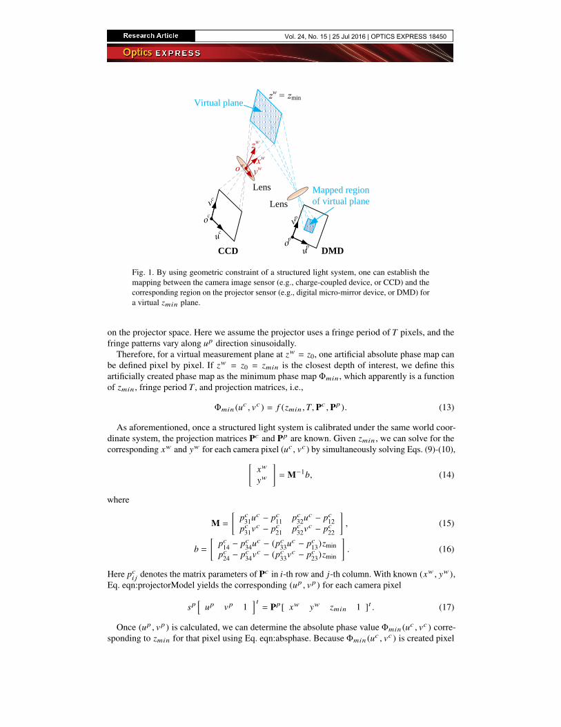
Figure 1 graphically illustrates that using simple geometric optics and pinhole models of thelenses, the camera sensor plane can be mapped to the projector sensor plane if the object planeis a flat surface that is precisely placed at zw = zmin . Once the mapped region is found onthe projector sensor plane, the corresponding phase map can be pre-defined. Therefore, for thevirtually defined zmin plane, the corresponding phase Φmin can be precisely created. In thispaper, we propose to use the artificially created phase map Φmin for absolute phase unwrapping.
Mathematically, for a given camera pixel (uc , vc ), if we know zw value, all seven unknownsincluding (up , vp ) can be uniquely solved using Eqs. eqn:cameraModel-eqn:projectorModel. If(up , vp ) is known, the corresponding absolute phase value for that camera pixel (uc , vc ) can beuniquely defined as
Fig. 1. By using geometric constraint of a structured light system, one can establish themapping between the camera image sensor (e.g., charge-coupled device, or CCD) and thecorresponding region on the projector sensor (e.g., digital micro-mirror device, or DMD) fora virtual zmin plane.
on the projector space. Here we assume the projector uses a fringe period of T pixels, and thefringe patterns vary along up direction sinusoidally.
Therefore, for a virtual measurement plane at zw = z0, one artificial absolute phase map canbe defined pixel by pixel. If zw = z0 = zmin is the closest depth of interest, we define thisartificially created phase map as the minimum phase map Φmin , which apparently is a functionof zmin , fringe period T , and projection matrices, i.e.,
Φmin (uc , vc ) = f (zmin ,T, Pc , Pp ). (13)
As aforementioned, once a structured light system is calibrated under the same world coor-dinate system, the projection matrices Pc and Pp are known. Given zmin , we can solve for thecorresponding xw and yw for each camera pixel (uc , vc ) by simultaneously solving Eqs. (9)-(10),[
denotes the matrix parameters of Pc in i-th row and j-th column. With known (xw , yw ),Eq. eqn:projectorModel yields the corresponding (up , vp ) for each camera pixel
sp[
up vp 1] t
= Pp[ xw yw zmin 1 ]t . (17)
Once (up , vp ) is calculated, we can determine the absolute phase value Φmin (uc , vc ) corre-sponding to zmin for that pixel using Eq. eqn:absphase. Because Φmin (uc , vc ) is created pixel
to pixel on the camera imaging sensor, such a phase map can be used to unwrap the phase mappixel by pixel. And since this phase is defined on the projector space, the obtained unwrappedphase by referring to Φmin (uc , vc ) is absolute.
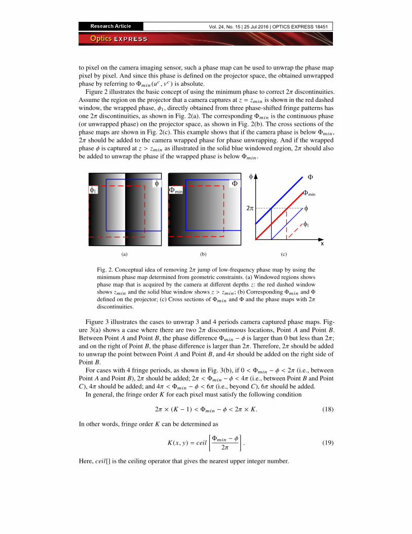
Figure 2 illustrates the basic concept of using the minimum phase to correct 2π discontinuities.Assume the region on the projector that a camera captures at z = zmin is shown in the red dashedwindow, the wrapped phase, φ1, directly obtained from three phase-shifted fringe patterns hasone 2π discontinuities, as shown in Fig. 2(a). The corresponding Φmin is the continuous phase(or unwrapped phase) on the projector space, as shown in Fig. 2(b). The cross sections of thephase maps are shown in Fig. 2(c). This example shows that if the camera phase is below Φmin ,2π should be added to the camera wrapped phase for phase unwrapping. And if the wrappedphase φ is captured at z > zmin as illustrated in the solid blue windowed region, 2π should alsobe added to unwrap the phase if the wrapped phase is below Φmin .
A B A B C
min
x x
2
6
2
min
min
2
min
x(a)
A B A B C
min
x x
2
6
2
min
min
2
min
x(b)
A B A B C
min
x x
2
6
2
min
min
2
min
x
(c)
Fig. 2. Conceptual idea of removing 2π jump of low-frequency phase map by using theminimum phase map determined from geometric constraints. (a) Windowed regions showsphase map that is acquired by the camera at different depths z: the red dashed windowshows zmin and the solid blue window shows z > zmin ; (b) Corresponding Φmin and Φdefined on the projector; (c) Cross sections of Φmin and Φ and the phase maps with 2πdiscontinuities.
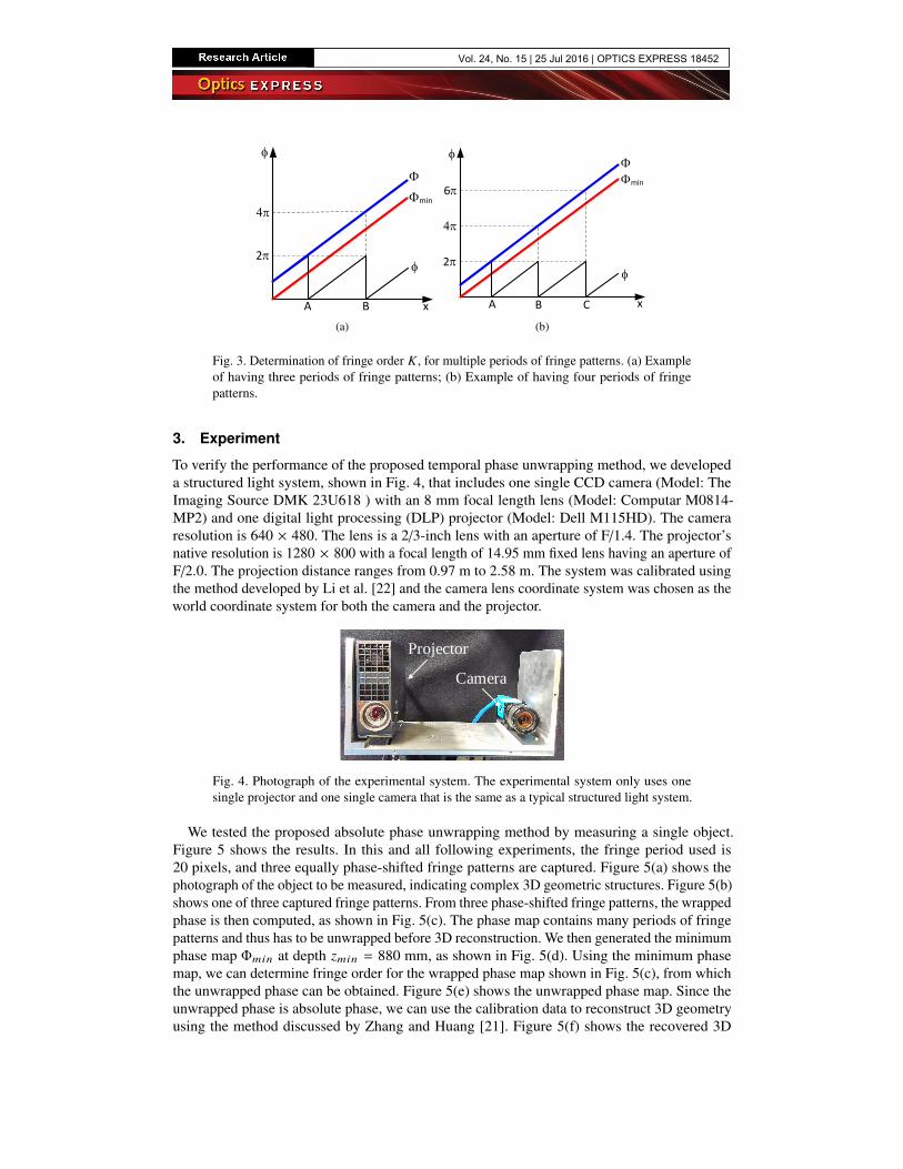
Figure 3 illustrates the cases to unwrap 3 and 4 periods camera captured phase maps. Fig-ure 3(a) shows a case where there are two 2π discontinuous locations, Point A and Point B.Between Point A and Point B, the phase difference Φmin − φ is larger than 0 but less than 2π;and on the right of Point B, the phase difference is larger than 2π. Therefore, 2π should be addedto unwrap the point between Point A and Point B, and 4π should be added on the right side ofPoint B.
For cases with 4 fringe periods, as shown in Fig. 3(b), if 0 < Φmin − φ < 2π (i.e., betweenPoint A and Point B), 2π should be added; 2π < Φmin − φ < 4π (i.e., between Point B and PointC), 4π should be added; and 4π < Φmin − φ < 6π (i.e., beyond C), 6π should be added.
In general, the fringe order K for each pixel must satisfy the following condition
2π × (K − 1) < Φmin − φ < 2π × K. (18)
In other words, fringe order K can be determined as
K (x , y) = ceil[Φmin − φ
2π
]. (19)
Here, ceil[] is the ceiling operator that gives the nearest upper integer number.
Fig. 3. Determination of fringe order K , for multiple periods of fringe patterns. (a) Exampleof having three periods of fringe patterns; (b) Example of having four periods of fringepatterns.
3. Experiment
To verify the performance of the proposed temporal phase unwrapping method, we developeda structured light system, shown in Fig. 4, that includes one single CCD camera (Model: TheImaging Source DMK 23U618 ) with an 8 mm focal length lens (Model: Computar M0814-MP2) and one digital light processing (DLP) projector (Model: Dell M115HD). The cameraresolution is 640 × 480. The lens is a 2/3-inch lens with an aperture of F/1.4. The projector’snative resolution is 1280 × 800 with a focal length of 14.95 mm fixed lens having an aperture ofF/2.0. The projection distance ranges from 0.97 m to 2.58 m. The system was calibrated usingthe method developed by Li et al. [22] and the camera lens coordinate system was chosen as theworld coordinate system for both the camera and the projector.
Projector
Camera
Fig. 4. Photograph of the experimental system. The experimental system only uses onesingle projector and one single camera that is the same as a typical structured light system.
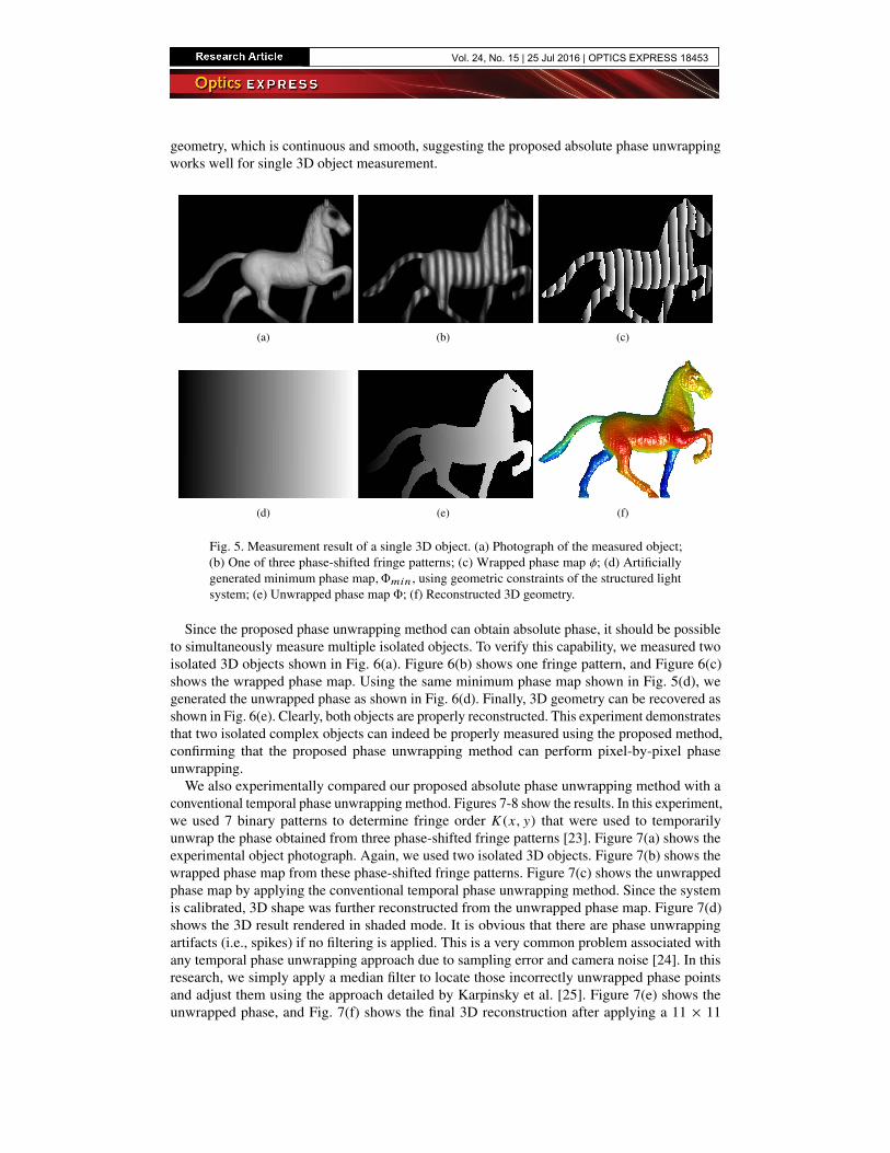
We tested the proposed absolute phase unwrapping method by measuring a single object.Figure 5 shows the results. In this and all following experiments, the fringe period used is20 pixels, and three equally phase-shifted fringe patterns are captured. Figure 5(a) shows thephotograph of the object to be measured, indicating complex 3D geometric structures. Figure 5(b)shows one of three captured fringe patterns. From three phase-shifted fringe patterns, the wrappedphase is then computed, as shown in Fig. 5(c). The phase map contains many periods of fringepatterns and thus has to be unwrapped before 3D reconstruction. We then generated the minimumphase map Φmin at depth zmin = 880 mm, as shown in Fig. 5(d). Using the minimum phasemap, we can determine fringe order for the wrapped phase map shown in Fig. 5(c), from whichthe unwrapped phase can be obtained. Figure 5(e) shows the unwrapped phase map. Since theunwrapped phase is absolute phase, we can use the calibration data to reconstruct 3D geometryusing the method discussed by Zhang and Huang [21]. Figure 5(f) shows the recovered 3D
geometry, which is continuous and smooth, suggesting the proposed absolute phase unwrappingworks well for single 3D object measurement.
(a) (b) (c)
(d) (e) (f)
Fig. 5. Measurement result of a single 3D object. (a) Photograph of the measured object;(b) One of three phase-shifted fringe patterns; (c) Wrapped phase map φ; (d) Artificiallygenerated minimum phase map,Φmin , using geometric constraints of the structured lightsystem; (e) Unwrapped phase map Φ; (f) Reconstructed 3D geometry.
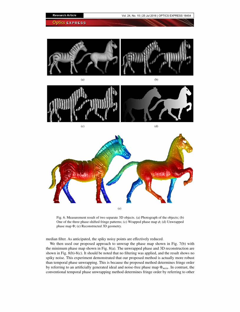
Since the proposed phase unwrapping method can obtain absolute phase, it should be possibleto simultaneously measure multiple isolated objects. To verify this capability, we measured twoisolated 3D objects shown in Fig. 6(a). Figure 6(b) shows one fringe pattern, and Figure 6(c)shows the wrapped phase map. Using the same minimum phase map shown in Fig. 5(d), wegenerated the unwrapped phase as shown in Fig. 6(d). Finally, 3D geometry can be recovered asshown in Fig. 6(e). Clearly, both objects are properly reconstructed. This experiment demonstratesthat two isolated complex objects can indeed be properly measured using the proposed method,confirming that the proposed phase unwrapping method can perform pixel-by-pixel phaseunwrapping.
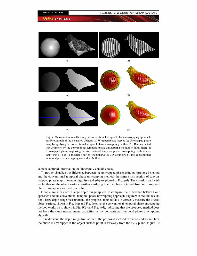
We also experimentally compared our proposed absolute phase unwrapping method with aconventional temporal phase unwrapping method. Figures 7-8 show the results. In this experiment,we used 7 binary patterns to determine fringe order K (x , y) that were used to temporarilyunwrap the phase obtained from three phase-shifted fringe patterns [23]. Figure 7(a) shows theexperimental object photograph. Again, we used two isolated 3D objects. Figure 7(b) shows thewrapped phase map from these phase-shifted fringe patterns. Figure 7(c) shows the unwrappedphase map by applying the conventional temporal phase unwrapping method. Since the systemis calibrated, 3D shape was further reconstructed from the unwrapped phase map. Figure 7(d)shows the 3D result rendered in shaded mode. It is obvious that there are phase unwrappingartifacts (i.e., spikes) if no filtering is applied. This is a very common problem associated withany temporal phase unwrapping approach due to sampling error and camera noise [24]. In thisresearch, we simply apply a median filter to locate those incorrectly unwrapped phase pointsand adjust them using the approach detailed by Karpinsky et al. [25]. Figure 7(e) shows theunwrapped phase, and Fig. 7(f) shows the final 3D reconstruction after applying a 11 × 11
Fig. 6. Measurement result of two separate 3D objects. (a) Photograph of the objects; (b)One of the three phase-shifted fringe patterns; (c) Wrapped phase map φ; (d) Unwrappedphase map Φ; (e) Reconstructed 3D geometry.
median filter. As anticipated, the spiky noisy points are effectively reduced.We then used our proposed approach to unwrap the phase map shown in Fig. 7(b) with
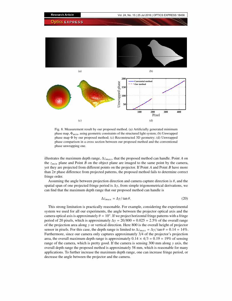
the minimum phase map shown in Fig. 8(a). The unwrapped phase and 3D reconstruction areshown in Fig. 8(b)-8(c). It should be noted that no filtering was applied, and the result shows nospiky noise. This experiment demonstrated that our proposed method is actually more robustthan temporal phase unwrapping. This is because the proposed method determines fringe orderby referring to an artificially generated ideal and noise-free phase map Φmin . In contrast, theconventional temporal phase unwrapping method determines fringe order by referring to other
Fig. 7. Measurement results using the conventional temporal phase unwrapping approach.(a) Photograph of the measured objects; (b) Wrapped phase map φ; (c) Unwrapped phasemap by applying the conventional temporal phase unwrapping method; (d) Reconstructed3D geometry by the conventional temporal phase unwrapping method without filter; (e)Unwrapped phase map using the conventional temporal phase unwrapping method afterapplying a 11 × 11 median filter; (f) Reconstructed 3D geometry by the conventionaltemporal phase unwrapping method with filter.
camera captured information that inherently contains noise.To further visualize the difference between the unwrapped phase using our proposed method
and the conventional temporal phase unwrapping method, the same cross section of two un-wrapped phase maps shown in Figs. 7(e) and 8(b) are plotted in Fig. 8(d). They overlap well witheach other on the object surface, further verifying that the phase obtained from our proposedphase unwrapping method is absolute.
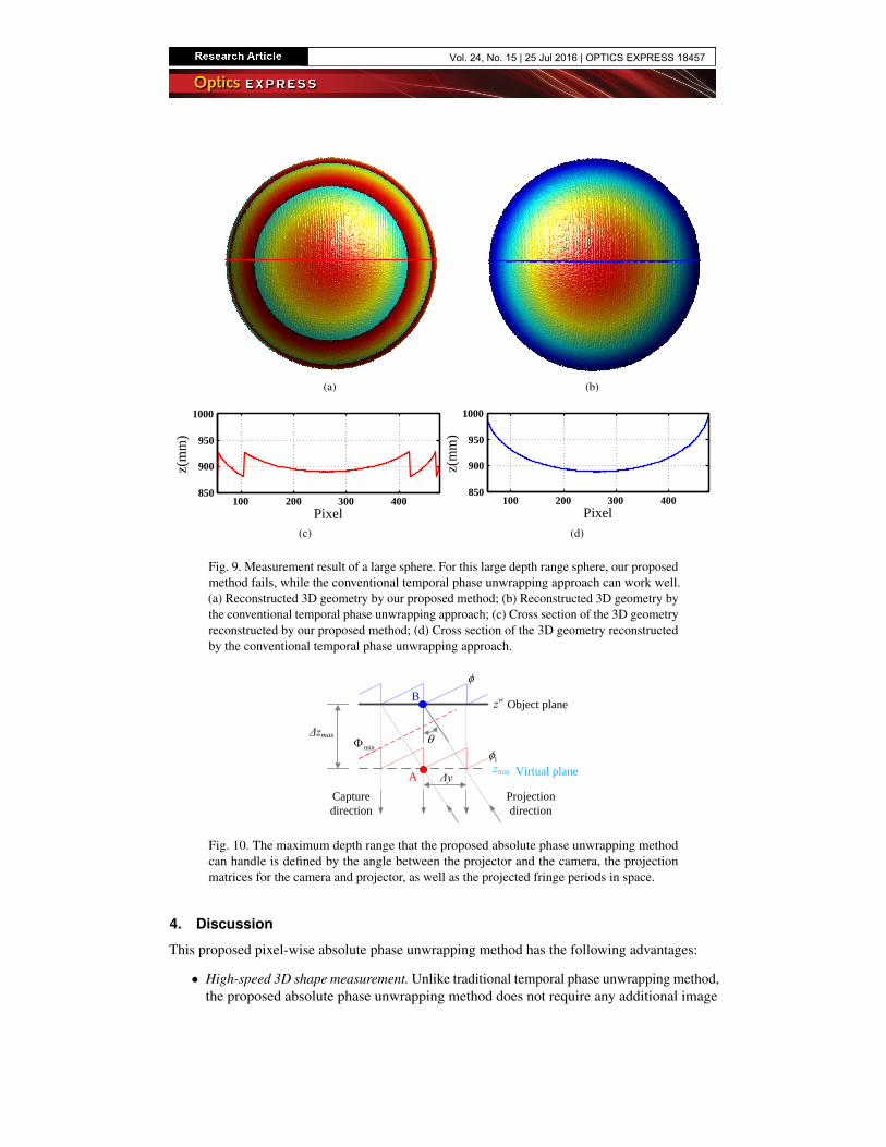
Finally, we measured a large depth range sphere to compare the difference between ourapproach and the conventional temporal phase unwrapping approach. Figure 9 shows the results.For a large depth range measurement, the proposed method fails to correctly measure the overallobject surface, shown in Fig. 9(a) and Fig. 9(c); yet the conventional temporal phase unwrappingmethod works well, shown in Fig. 9(b) and Fig. 9(d), indicating that the proposed method doesnot have the same measurement capacities as the conventional temporal phase unwrappingalgorithm.
To understand the depth range limitation of the proposed method, we need understand howthe phase is unwrapped if the object surface point is far away from the zmin plane. Figure 10
Fig. 8. Measurement result by our proposed method. (a) Artificially generated minimumphase map,Φmin , using geometric constraints of the structured light system; (b) Unwrappedphase map Φ by our proposed method; (c) Reconstructed 3D geometry; (d) Unwrappedphase comparison in a cross section between our proposed method and the conventionalphase unwrapping one.
illustrates the maximum depth range, ∆zmax , that the proposed method can handle. Point A onthe zmin plane and Point B on the object plane are imaged to the same point by the camera,yet they are projected from different points on the projector. If Point A and Point B have morethan 2π phase difference from projected patterns, the proposed method fails to determine correctfringe order.
Assuming the angle between projection direction and camera capture direction is θ, and thespatial span of one projected fringe period is ∆y, from simple trigonometrical derivations, wecan find that the maximum depth range that our proposed method can handle is
∆zmax = ∆y/ tan θ. (20)
This strong limitation is practically reasonable. For example, considering the experimentalsystem we used for all our experiments, the angle between the projector optical axis and thecamera optical axis is approximately θ = 10◦. If we project horizontal fringe patterns with a fringeperiod of 20 pixels, which is approximately ∆y = 20/800 = 0.025 = 2.5% of the overall rangeof the projection area along y or vertical direction. Here 800 is the overall height of projectorsensor in pixels. For this case, the depth range is limited to ∆zmax = ∆y/ tan θ = 0.14 = 14%.Furthermore, since our camera only captures approximately 3/4 of the projector’s projectionarea, the overall maximum depth range is approximately 0.14 × 4/3 = 0.19 = 19% of sensingrange of the camera, which is pretty good. If the camera is sensing 300 mm along y axis, theoverall depth range the proposed method is approximately 58 mm, which is reasonable for manyapplications. To further increase the maximum depth range, one can increase fringe period, ordecrease the angle between the projector and the camera.
Fig. 9. Measurement result of a large sphere. For this large depth range sphere, our proposedmethod fails, while the conventional temporal phase unwrapping approach can work well.(a) Reconstructed 3D geometry by our proposed method; (b) Reconstructed 3D geometry bythe conventional temporal phase unwrapping approach; (c) Cross section of the 3D geometryreconstructed by our proposed method; (d) Cross section of the 3D geometry reconstructedby the conventional temporal phase unwrapping approach.
CCD DMD
zw = zmin
owywxw
zw
Lens
Lens
Virtual plane
Mapped region of virtual plane
zmin
zw
Projectiondirection
Capturedirection
Δzmax
min1
Δy
B
A
Object plane
Virtual plane
Fig. 10. The maximum depth range that the proposed absolute phase unwrapping methodcan handle is defined by the angle between the projector and the camera, the projectionmatrices for the camera and projector, as well as the projected fringe periods in space.
4. Discussion
This proposed pixel-wise absolute phase unwrapping method has the following advantages:
• High-speed 3D shape measurement. Unlike traditional temporal phase unwrapping method,the proposed absolute phase unwrapping method does not require any additional image
acquisition, and thus it is more suitable for high-speed applications.
• High-speed processing. The proposed method is inherently a pixel operation that does notrefer to neighboring pixels or using any filters; the processing speed is fast especially if itis implemented on a parallel processor (e.g., graphics processing unit, GPU).
• Simple system setup. Unlike those state-of-art methods using one more camera without re-quiring more image acquisition, the proposed method does not change the single-projectorand single-camera structured light system set up, and thus it can be directly employed byany conventional structured light system.
• Simultaneous multiple objects measurement. Similar to temporal phase unwrappingmethod, the proposed absolute phase unwrapping is pixel by pixel, and thus can be used tomeasure multiple objects at exactly the same time, as demonstrated by the experimentaldata in Sec. 3.
• Robustness in fringe order determination. The phase unwrapping artifacts (i.e. spikes)are minimum without any filtering, indicating that fringe order determination is veryrobust. This is because the proposed method determines fringe order by referring to anartificially generated ideal absolute phase map Φmin without any noise. In comparison,the conventional temporal phase unwrapping method determines fringe order by referringto other camera captured information that contains noise.
However, this proposed absolute phase unwrapping method is not trouble free, as demonstratedin our experimental data (Fig. 9). The major limitations are:
• Confined measurement depth range. As mentioned above, the maximum measurementdepth range that the proposed approach can handle is within 2π changes in phase domainfrom the object plane to the minimum phase generation plane. In other words, any pointon the object surface should not be too far away from zmin such that it will cause morethan 2π changes. This is practically reasonable since the overall maximum depth range forour measurement system is approximately 19% of the camera’s overall sensing range.
• Good zmin estimation. Since the maximum depth range is limited by the distance from zmin
plane to object plane, more accurate use of zmin plane leads to larger depth measurementrange; and incorrect use of zmin plane could lead to incorrect phase unwrapping. In ourresearch, we coincide the world coordinate system with the camera lens coordinate. Bydoing so, zmin plane has the minimum zw value for 3D reconstruction. By doing so, onecan estimate zmin of interest by a variety of means, one of which being the use of a rulerto measure the distance from the closet object point to the camera lens.
Even with these limitations, the proposed pixel-by-pixel absolute phase unwrapping withoutthe use of any additional image or hardware can substantially benefit the optical metrology field,especially for applications where high-speed absolute 3D shape measurement is required.
5. Summary
This paper has presented a method to unwrap phase pixel by pixel by referring to the artificialminimum phase map created solely using geometric constraints of the structured light system.Unlike conventional temporal phase unwrapping algorithms that require one to capture moreimages, the proposed absolute phase unwrapping method requires no additional image acquisition.Compared with those absolute phase measurement methods that use one additional camera, theproposed method does not require any additional camera to obtain absolute phase. Since it doesnot require any additional image acquisition or another camera, the proposed method has the
advantage of measurement speed without increasing system complexity or cost. Experimentalresults demonstrated the success of our proposed pixel-by-pixel absolute phase unwrappingmethod. Despite its confined depth range, the proposed method is of significance to applicationswhere high-speed 3D absolute shape measurement is necessary.
Acknowledgments
We would like to thank Beiwen Li, Chufan Jiang, and Bogdan Vlahov for proofreading andcritiquing the entire paper. We also thank other students for their kind discussions.
This study was sponsored by the National Science Foundation (NSF) under grant numbersCMMI-1521048. The views expressed in this paper are those of the authors and not necessarilythose of the NSF.