Planning, Installation and Maintenance Instructions 1 and 2 leaf Fire doors Smoke protection doors Sound insulated doors Security doors Multi-purpose doors Fire doors EI 30 - "Teckentrup 62" GB Fire doors EI 60 - "Teckentrup 62" GB Smoke protection doors S - "Teckentrup 62" GB Multi-purpose doors dw 64 - "Teckentrup 64" GB
Transcript
Planning, Installation and Maintenance Instructions 1 and 2 leaf
Fire doors Smoke protection doors
Sound insulated doors
Security doors Multi-purpose doors
Fire doors EI 30 - "Teckentrup 62" GB Fire doors EI 60 - "Teckentrup 62" GB Smoke protection doors S - "Teckentrup 62" GB Multi-purpose doors dw 64 - "Teckentrup 64" GB
2
These instructions apply for the following doors and are considered as an appendix for the approval of fire and smoke protection doors
Teckentrup 62 Fire resistant
Smoke proof
Sound proof
Burglar proof
Heat protection
*1) UD= W/(m²K)
Wind/ Water/
Air
EI 30-C (1 leaf) - x WK2 + 3 1.6 x EI 30-CS (1 leaf) x x WK2 + 3 1.6 x EI 30-C (2 leaf) - x WK2 + 3 1.6 x EI 30-CS (2 leaf)
x x WK2 + 3 1.6 x EI 60-C (1 leaf) - x WK2 + 3 1.6 x EI 60-CS (1 leaf) x x WK2 + 3 1.6 x EI 60-C (2 leaf) - x WK2 + 3 1.6 x EI 60-CS (2 leaf)
x x WK2 + 3 1.6 x S (1 leaf) - x S (2 leaf) - x dw64 (1 leaf) dw64 (2 leaf)
1) Details without glazing
3
Table of contents Designation Page Status 1 General Information 1.1 Requirements for fire, smoke protection, sound insulated, security doors 4-5 1.2 Wall thicknesses and types 6-7 1.3 Approved frames and frame backfilling 8-9 1.4 Installation and attachment information 9-11 2 Installation Situation 2.1 Prior to assembly check whether 12 2.2 Preparing the frame for installation 12-13 2.3 Connecting or disconnecting the door leaves (hinges) 13 2.4 Installation in solid [M] and autoclaved aerated concrete [PB] walls 14-16 3 Block Frame Installation 3.1 Block frame type 1 and type 1 MP 16 3.2 Block frame type 2 + 3 17 3.3 Block frame type 4 17 4 Installation in Prefabricated Walls 18-19 5 Installation in Steel Girders/Supports 20-21 6 Smoke Protection Details 21 7 Floor Connections 7.1 With floor recess 22 7.2 Without floor recess 22 7.3 With 4-sided frame and 4-sided rebate 23 7.4 With sill and 4-sided rebate for hatches and doors 23 7.5 With buffer 23 7.6 With bottom buffer seal 23 8 Seals 8.1 Frame seal 24 8.2 Rebate seal 24 8.3 Bottom seal 24-25 9 Installing and Adjusting Accessories 9.1 Adjusting the strike for 1-leaf doors 25 9.2 Height adjustment of the door 25 9.3 Securing the KO (supporting) hinge bolts 26 9.4 Aligning the hinges 26 9.5 Floor locking 26 10 Closing Devices 10.1 Spring hinge 27 10.2 Door closer 27 10.3 Hold open devices 28 10.4 Door selector 28 10.5 Driver flap 28 11 Locks and Door Fittings
11.1 Locks and door fittings for emergency exits and panic doors in accordance with EN 179 and EN 1125 29
11.2 Door handles 30 11.3 Geared handle for snap lock 30 11.4 Bar handle 31 11.5 Profile cylinder (provided by the customer) 31 11.6 Assembly of the protective door fittings and profile cylinder 32 12 Electrical Components 12.1 Reed contact 33 12.2 Bolt contact 33 12.3 Electronic door opener 34 12.4 Cable junction 34 12.5 Door leaf cut-outs 34 13 Further Door Versions 13.1 Glazing 35 13.2 Upper part for MP doors 35 13.3 Door functioning as an outer door 36 14 Disassembly of Doors 36 15 Painting (surface treatment) 36 16 Maintenance Instructions 37
4
1. General Information About these instructions:
• These installation instructions specify the current status of approval and testing • If other accessories, such as fittings, door handles, locks, closing devices, are
applied, always adhere the installation instructions of the respective parts • Electrical connections, e.g. for motor and block locks, electrical door openers, etc.,
have to be carried out by authorized personnel • These instructions are subject to technical changes
Symbol legend:
• Important, always observe this information
• Caution, pay attention to this information
• Note
• Additional requirements
1.1 Requirements for fire doors: • Install fire barriers in accordance with the corresponding approval and the
installation instructions. • The supplied products are approved. Modifications should only be carried out in
line with the specified measures. • Installed fire barriers have to be self-closing and equipped with the required fittings
for their intended use. • The operator is responsible for the perfect condition of the fire barrier. • Fire protection glass should only be replaced by qualified personnel. • Spring hinges are not permitted for the installation of fire barriers in autoclaved
aerated concrete and in installation walls made of plaster materials. • Fittings, door handles, locks and closing devices can only be used if verification of
suitability – building authority test certificate – is available and the installation regulations are observed.
• Plugs should only be used if they have been approved by building authorities or passed via fire and flammability tests, and the respective plug substrate and edge distance are taken into account.
• Backfilling of the wall has to be carried out in accordance with the installation regulations of the respective frames and the type of wall.
5
With additional smoke protection: • Smoke barriers should be equipped with door closers (except for hatches) as
closing devices and with profile cylinders. • The operator is responsible for the perfect condition of the fire-smoke barrier. • Modifications should only be carried out in line with the approved measures. • Wall sealing joints should be sealed with a silicone sealant. • Pay particular attention to the correct functioning of frame side and bottom seals
for smoke barriers. The seal has to be mitred accordingly and pushed close together in the upper corners of the frame.
With additional sound insulation: • Sound insulation can only be achieved if the walls, floor and ceiling have been
planned correctly. • The insulation values of these components have to be at least 10 dB above the
insulation value of the door; moreover, there should not be any acoustical bridges. • The installation of fire and sound insulated barriers has to occur with the utmost
care. Always ensure there are sufficient clearances and the frame side and bottom seal.
• The seal has to be mitred accordingly and pushed close together in the upper corners of the frame. Use a “rapid composite adhesive” to glue the corner joints.
• Completely back fill the frame with mortar. The wall connection has to be carefully established using plaster or a plastic sealant and the screed has to be separated in the threshold area.
Burglar protection: • Security doors require certain a type of installation. The frame has to be backfilled
in a pressure-resistant manner, precise clearances have to be observed and the wall brackets have to be attached correctly.
The requirements of the respective approvals and test certificates have to be observed when combining various products!
Multi-purpose doors: • The aforementioned requirements are not mandatory for multi-purpose doors.
However, particular attention should always be paid to the assembly and installation instructions.
6
1.2 Wall thicknesses and types - For fire and smoke protection doors
“Teckentrup 62” EI / EI-S
Masonry (without plaster)
Poroton [vertically
perforated clay brick] (without
plaster)
Concrete(without plaster)
Autoclaved aerated concrete
blocks and high
precision units 1)
Reinforced autoclaved
aerated concrete slabs 1)
Installation walls
EI 90 1)
Steel compo-nents
EI 30 (1 and 2 leaf) ≥115 ≥240(nT)/≥300(T) ≥100 ≥150 ≥150 ≥100 ≥EI 60 EI 60 (1 and 2 leaf) ≥115 ≥240(nT)/≥300(T) ≥100 ≥150 ≥150 ≥100 ≥EI 90
- For smoke protection doors “Teckentrup 62”
S Masonry (without plaster)
Poroton [vertically
perforated clay brick]
(without plaster)
Concrete (without plaster)
Autoclaved aerated concrete
blocks and high precision
units 1)
Reinforced autoclaved
aerated concrete slabs 1)
Steel components
S (1 and 2 leaf) ≥115 ≥240(nT)/≥300(T) ≥100 ≥150 ≥150
- For sound insulated doors 2) “Teckentrup 62”
EI / EI-S Masonry
(without plaster) Poroton [vertically perforated
clay brick] (without plaster)
Concrete (without plaster)
EI 30 (1 and 2 leaf) ≥115 ≥240(nT)/≥300(T) ≥100 EI 60 (1 and 2 leaf) ≥115 ≥240(nT)/≥300(T) ≥100
- For security doors “Teckentrup 62” EI / EI-S / S /
dw64
Masonry (without plaster)
Poroton [vertically
perforated clay brick]
(without plaster)
Concrete (without plaster)
Autoclaved aerated concrete blocks and high precision units 1)
1) FSA installed in autoclaved aerated concrete and prefabricated walls should always be equipped with a door closer.
2) For sound insulation, the insulation value of the wall has to be at least 10 dB higher than the insulation value of the door.
7
Wall types: Masonry DIN 1053 Part 1 1) Masonry strength class min. 12 Normal mortar of mortar group ≥ II Concrete DIN 1045 1) Strength class min. C 12/15 Poroton [vertically perforated clay brick] Z-17.1-261 1) Masonry strength class min. 12 Autoclaved aerated concrete blocks and high precision units DIN 4165 1) Strength class min. 4
Note: Once the mortar has set, correct backfilling cannot be tested simply by tapping and listening, since there is no shear resistance between the frame profile and the filling mortar!
1.4 Installation and attachment information 1.4.1 Clearances Table 3
Between the frame / door leaf
Between the door leaf / upper edge finished floor (OFF)
Between the door leaf / door leaf or
upper part (rebate)
„Teckentrup 62“ EI / EI-S / S /
dw64
1 and 2 leaf hinge side + top
“V”
1 leaf lock side
“W“
Fire protection
bottom „X“ *2)
Retractable bottom seal
“X“
Sliding threshold
seal “X“
Rabbet seal“X“
Door leaf/Door
leaf “Y“
Door leaf/Upper part
“Z” EI 30 EI 60
(1 leaf) 8 +1 - 4 6 +2
- 2 8 +7 - 4 8 +2
- 4 8 +2 - 1 8 +2
- 4 - -
EI 30 EI 60
(2 leaf) 8 +1 - 4 -
8 +7
- 4 8 +2 - 4 8 +2
- 1 8 +2 - 4 6 +1
- 1 -
S (1 leaf) 8 +1 - 2 6 +2
- 2 8 +7 - 4 8 +2
- 4 8 +2 - 1 8 +2
- 4 - -
S (2 leaf) 8 +1 - 2 - 8 +7
- 4 8 +2 - 4 8 +2
- 1 8 +2 - 4 6 +1
- 1 -
dw64 (1 leaf) 8 +1 - 2 8 +2
-2 8 +7 - 4 8 +2
- 4 8 +2 - 1 8 +2
- 4 - 6 +1 - 2
dw64 (2 leaf) 8 +1 - 2 - 8 +7
- 4 8 +2 - 4 8 +2
- 1 8 +2 - 4 6 +1
- 1 6 +1 - 2
2) For optical reasons, we recommend you to adhere to the nominal size for a bottom clearance or to confer with the client before utilizing the tolerances!
10
1.4.2 General installation information • Place the door element (frame with closed door leaf) in the opening, align the element
(vertical, horizontal and plumb position) and use wedges to fix it into position – observe the metre level at the side of the frame.
• Use spacers to create clearances (see table 3 – clearances). • Spread the lateral frame parts to prevent them being bent or twisted when plastering
with mortar. • After assembling the door, ensure that it is not moved while plastering with mortar and
while the mortar is setting. • Before the frame is plastered with mortar, it is important to carefully check correct
functioning of the door.
1.4.3 General attachment information: • Ensure that the substrate onto which the door is to be mounted is suitable and
approved for the specified load. • For you own safety, always carry out the installation steps in the order specified in
these instructions. • The door has to be connected to the adjacent components in a way that the forces
which occur during automatic closing of the fire barrier and the deformation which occurs during a fire (or for smoke protection doors – temperatures up to max. 200°C) are absorbed by the fixings. It is also important that these forces do not endanger the stability of adjacent components (walls, ceiling and floor).
Safety instructions: • Always observe the maximum permissible loads when using lifting gear and devices. • Only use intact and certified lifting devices (assembly cranes, fork lifts) and lifting gear
(cables, chains, belts). • Before lifting the door leaf, ensure that the load is secured correctly and that it can
neither become loose nor slip. The door leaf can suddenly jerk and swing – danger risk of injuries
• During assembly avoid wind loads on the not fully assembled door, e.g. in thoroughfares or subways. Close or secure all openings in advance.
• During the entire assembly period ensure that the door leaf cannot fall down or be knocked down.
For 1 leaf doors: Dimension “A” = Active door leaf width + inactive door leaf width + 2x dimension “W” + 1x dimension “Z” Dimension “B” = Door leaf height + 1x dimension “W” + 1x dimension “Y“
11
1.4.4 For plug attachment • Only use plugs which are building authority approved and suitable for our fire
doors or plugs which we have certified (fire and flammability test) (see table 4). Furthermore, the plugs have to be suitable for the substrate.
• Plug assembly should only be carried out by specially trained personnel. • For perforated and hollow bricks – only drill the hole for the plug with a rotary drill
(hammer switched off). • Always pay attention to the diameter and depth of the hole (see table 4). • For solid bricks or concrete – always clean the hole with compressed air or a
suitable brush before inserting the plug (also refer to the installation instructions of the plug manufacturer).
• Use suitable setting tools and devices for plug attachment. • Observe the specified tightening torque Tinst when fitting the plug (see table 4). • Only use the plugs with the pre-assembled safety screws (for plastic plugs) or in
the supplied, pre-assembled state (do not swap individual plug parts)! • Always observe the specified plug distances “e” and edge distances “e1”.
Particularly for any alternative holes which may be required (e.g. due to internal reinforcements).
Table 4
Pos Approved wall plugs for fire / smoke protection doors or hatches
Application for
Nominal
drill diameter
[mm]
Min. wall bracket
depth [mm]
Min. bore hole depth
[mm]
Tightening torque
Tinst [Nm]
1 fischer FUR 10x100 SS
Masonry / Concrete 10 70 110 -
2 fischer FUR 10x160 SS
Masonry / Concrete 10 70 170 -
3
fischer FUR 10x100 T
Masonry / Concrete / Autoclaved
aerated concrete*)
10 70 110 -
4
fischer FUR 10x160 T
Masonry / Concrete / Autoclaved
aerated concrete*)
10 70 170 -
5 fischer S10 H100 RSS
Autoclaved aerated
concrete*) 10 70 110 -
6 fischer S10 H160 RSS
Autoclaved aerated
concrete*) 10 70 170 -
7 fischer FH 12/-S
Alternative for concrete 12 60 90 25
*) In accordance with the approval, always use a frame wall bracket when drilling autoclaved aerated concrete!
12
Part 2 – Installation Situation 2.1 Prior to assembly check whether: • The wall type is suitable for installing the door • The height of the floor is known • The opening direction (left/right) is specified and whether the door should close
inwards or outwards • There are any additional building specifications which need to be considered • The protective boxes (on the frame) have to be chiselled out.
To guarantee correct functioning of the door, never remove the protective boxes!
2.1.1 Determining of the emergency exit side (GS) or hinge side (BS) or opposite hinge side (BGS) for security doors. [the active door leaf DIN right – view from the inside is displayed]
2.2 Preparing the frame for installation • The frames are sometimes
transported as a pack and have to be assembled
2.2.1 Assembling the corner frame - Type [AV] -1: • Connect the frames • Use the ST4.8x13 screws (1) to
assemble the corner connectors
- Type [AV] -2: • Connect the frames • Tighten the M8x8 set screw (2) in the
weld parts - 2.2.2 Assembling the closed frame - Type [AV] -1: • Connect the closed frame • Use the ST4.8x13 screws (3) to
assemble the corner connectors
13
- Type [AV] -2: • Connect the closed frame • Tighten the M8x8 set screws (1) in the
weld parts
2.2.3 Assembling the counter frame: • Connect the counter frame • Tighten the M8x8 set screws (2) in the
weld parts
2.2.4 Sill - Corner, closed and counter frame
with a sill • Use ST 4.8x16 sheet metal screws (3)
and snap nuts to connect the sill to the frame
- Corner, closed and counter frame without a sill
Spread the lateral frame parts to prevent them being bent or twisted when plastering with mortar
2.3 Connecting or disconnecting the door leaves (hinges) - Connecting the door leaves: • Hang the door leaves on the hinges • Slightly lubricate the hinge bolts (4) • Insert the ball bearing (5) [and
possible spacers (6) see point. 9.2] • Tap in the hinge holts (4)
- Disconnecting the door leaves: • Remove any hinge protection [see
point 9.3] • Tap out the hinge bolts (4) towards
the middle of the door (TM) • Remove the ball bearing (5) [and
possible spacers (6)]
14
2.4 Installation in solid [M] and autoclaved aerated concrete [PB] walls
2.4.1 Attaching the corner frame • Additionally for autoclaved aerated
concrete – Insert anchor brackets (3) (the distance between brackets should be the same as the frame fixing points) using wall plugs Ø10 (2) [see point 1.4.4 – pos. 5] Alternatively – Attach connectors (4) to the fixing wall brackets using ST5.5x38 countersunk screws (5) and washers
• Insert the frame with or without the door leaf and align it (vertical, horizontal and plumb position)
• Observe the metre level (MR) on the side of the frame
• With door leaf – Open the door 90° and wedge it
• Use the adjusting screws (1) to fix the frame
Note: If the installation site is uneven, use levelling pieces to support the adjusting screws
• 1 leaf: In the hinge area, 2 leaves: Plug and fix the two upper hinge fixing points of the specified fixing points or for autoclaved aerated concrete use plugs Ø10 (4) in the connectors [see point 1.4.4 for solid - Pos. 3 / autoclaved aerated concrete - Pos. 4]. For autoclaved aerated concrete with anchor brackets – Attach the frame to the anchor brackets using ST5.5x38 countersunk screws (5) and washers
• Without door leaf – Hang the door leaf on the hinges
• Check the installation of the door leaf, possibly re-adjust the frame via the adjusting screws (1)
• Plug and fix the frame at all the other fixing points
• Attach the protective caps (6) • Backfill the frame with mortar (M)
Important: Always use washers with ST5.5 countersunk screws (5) to prevent the heads of the screws passing through the holes
Caution: Make sure that the plugs spread at the top and bottom
Important: Do not move the door while the mortar is setting
15
2.4.2 Attaching a closed or counter frame
- Closed frame • Use a plug Ø10 (2) [see point 1.4.4 Pos.
5] to fix the wall bracket (1) according to the distance diagram
• Screw the closed frame together [see point 2.2.2]
• Push the frame into the wall opening • Plug and fix the frame as described
under point. 2.4.1 • Erect the frame support using a power
screwdriver / screwdriver and insert the frame in an upright position
• Plaster the frame with mortar
- Counter frame • Assemble the corner frame as
described under point 2.4.1 • Backfill the corner frame with mortar • Insert the wall bracket (1) for the
counter frame [see point 2.4.2] • Screw the counter frame together [see
point 2.2.3] • Fill the counter frame with mineral
wool • Screw the counter frame to the corner
frame (ST4.8x38 self-drilling screws (3); (e≤500) or weld (s: l≥20)
• Erect the frame support, see closed frame above
* only for 2 leaf doors 1) for modular dimension
height >2500 2) for modular dimension
width >2500
16
2.4.3 Attaching special frames - Expansion joint frames • Install the frame according to the
standard frame
- Frames with shadow groove • Install frames according to the
standard frame • The shadow groove side of the frame
also has to be plastered
3. Block Frame Installation Use pressure-resistant supports (steel or hardwood) to level any unevenness of the wall / ceiling in horizontal and vertical direction. Any resulting spaces (ZR) up to 6mm are filled with B1 sealing compound [e.g. silicone, acrylic or PU]. spaces >6mm have to be filled with A1 mineral wool [rockwool T>1000°C] and sealed with B1 sealing compound or with mortar. The max. gap is 15 mm, otherwise correct attachment cannot be achieved.
3.1 Block frame type 1 and type 1-MP • Plug and fix the u-shaped profiles at
the top and then at the side [plug (1) see Fig. 3] and subsequently weld them together
• Backfill the block frame with plasterboard strips (mineral wool is also possible for MP doors). Do not plaster the door with mortar until door installation has been completed (for MP doors – fill via the filling holes and subsequently seal them with the supplied stoppers)
• Insert and align the door with the frame
• Type 1: Connect the frame and the u-shaped profile to the bar (2) [in the wall plug area]
• Optionally cover it using the aluminium covering and clips (3); e≤300
3.2 Block frame type 2 + 3 - Type 2 – disassembled (between or
in front of the wall) • Plug and fix the u-shaped profile at the
top and then at the side [plug (1) see fig. 3] and connect using M6x10 countersunk bolts (2)
• Fill the frame parts with plasterboard strips (mineral wool is also possible for MP doors)
• Position and align the door with the frame in the wall opening
• Screw the frame and the u-shaped profile together [ST4.2x22 self-drilling screw (3); e≤300, optionally weld together [ (S: l≥20); e≤300]
- Type 3 – pre-assembled • Insert the complete door with the block
frame into the wall opening and align it • Plug and fix the block frame [plug (1) see
fig. 3]
3.3 Block frame type 4 • Insert the complete door with the block
frame into the wall opening and align it Important: Attach pressure-resistant supports (4) at the fixing points
• Plug and fix the block frame
Caution: Only flush installation is possible for doors with a top door closer or recesses for handle/top door closer, etc.
Type 3
Type 2 - in front of the wall
Type 2 - between the wall
18
4. Installation in Prefabricated Walls: • Check the clear wall opening:
Wall opening width = modular dimension of the door + 20 Wall opening height = modular dimension of the door + 10
4.1 Prerequisites for the installation of fire doors
• Reinforcement profiles (1) of min. U50x40x2 in the door opening area
• Cut-outs in the reinforcement profiles for mounting parts, such as an electric opener, have to be reinforced by sheet metal strips (2) ≥2 mm thick
4.1.1 Backfilling of the frame: • Backfill corner, counter and closed
frames with “plasterboard strips“ GKB DIN 18180 or mortar
Caution: Only backfill the frame with mortar once the frame has been fixed into position
4.1.2 Attachment without counter frame: • Backfill the frame • Insert and align the door as described
under point 2.4.1 • Attach to the reinforcement profiles
using ST.5.5x38 countersunk screws (3) and washers
• Push the 70x0.4 sheet metal strips (4) between the plasterboard and use the dry wall screws (5) to fix it to the reinforcement profile
• Use the dry wall screws (6) to fix it to the frame through the plasterboard
• For thicker cladding: Screw connectors (7) ≥2 thick to the fixing wall bracket using ST5.5x38 countersunk screws (8) and washers, subsequently fix these to the reinforcement profiles using ST4.8 hexagon head screws (9)
Important: Always use washers to prevent the heads of the countersunk screws passing through the holes
The profiles have to be fastened to each other and to the floor and ceiling in the H-system
19
4.1.3 Attachment without counter frame: • Connect the counter frame parts • Tighten the set screws (1) M8x8 in the
weld parts • Backfill the frame • Position the fixing clamps (2), 3-4
clamps at the side and 2-3 clamps at the top
• Push the counter frame against these and use the ST4.8x60 or M5x50 countersunk screws (3) to attach it
4.1.4 Installation with closed frame: • Position the upper frame part in the
opening, insert the lateral frame parts in the order displayed
• Use M5x10 oval head screws (4) to connect the frame corners
• Backfill the frame • Hang the door on its hinges and align
it • Fasten the front and rear frame part
using the ST4.8x60 or. M5x50 countersunk screws (5)
20
5 Installation in Steel Girders/Supports 5.1 Installation of fire doors in steel constructions with fire-proof cladding:
Caution: - The required minimum thickness “d” of the cladding for EI30 has to correspond to
EI60 cladding and EI60 has to correspond to EI90 cladding for steel girders and supports
- Minimum requirements whilst taking the static requirements into consideration - The cladding should be modified as little as possible - Concreting, plastering with mortar or bricking up the intermediate flange spaces is
permissible (not required for fire protection)
5.1.1 General attachment: • Position and number of the fixing
points according to the frame specifications
• If necessary, partially fix an assembly flange (1) 40x5 in the attachment area
• Drill through the insulation and insert a suitable spacer sleeve (2) for the fastening screw (3)
• Backfill the frame (see point 1.3.2) • Fix using ≥M6 screws (3) ≥M6
5.1.2 Attaching the corner frame • Use M6 countersunk screws (3) to
fasten the corner frame • Fix the corner frame filled with GKB –
GKF plasterboard strips (4) onto the frame using a ST4.8 countersunk screw (5) ; e≤500
5.1.3 Attaching the closed and counter frame • Attach the wall bracket (6) (distances
according to 2.4.2) using M6 screws (7) • Attach the frame as described under
point 5.1.2 • Alignment of the wall brackets and
further possible attachments as described under point 2.4.2
5.1.4 Attaching the closed or clasping counter frame • Position the 40x1.5 adapted bracket
(8); e≥500 at the rear and fasten it using M5 oval head screws (9)
• Screw on the closed/corner frame as described under point 5.1.2
• Use ST4.8x16 countersunk screws (10) to fasten the rear frame piece
Basic diagram of the installation situations
21
5.1.5 Attaching the block frame • Depending on the block frame type,
use M8 hexagon head or countersunk screws (3) to attach the block frame , see point 3
5.2 Installation of MP doors in steel constructions • Position the door in the opening and
align it • Weld the frame in the hinge and lock
area using flat iron pieces (4) to the steel profiles (5) provided by the customer, alternatively use ST6.3 countersunk screws (7)
• Foam the corner frame with PU (Caution! Use very little foam), alternatively fill with PU joint sealing cord or mineral wool
• Adapt the supplied angle trim (6) 30x30x2, horizontally between the vertical strips (without separation)
• Weld the strips to the frame and steel profile (especially above and below the hinges)
• Process the welding seam and cold galvanize it
6. Smoke Protection Details - Smoke protection
Wall sealing joints should be sealed with a permanently elastic material (SA)
LE =clear iron dimension (modular dimension + 10mm per side) BRM = Modular dimension of the door
Opposite hinge side
Welding S1 = l≥15: Hinge side
22
7. Floor Connections: Doors which are used as emergency exits should not have bottom buffers or threshold strips; only semi-circular-shaped thresholds up to 5 mm high are permitted. For operational purposes, semi-circular-shaped thresholds cannot be used in hospitals, nursing homes, etc. (risk of stumbling, transportation of bedridden people).
7.1 With floor recess (30 mm): • Install the door with a sill (1)
Note: The sill can be removed after installation of the frame (plugged, cast and cured)
7.2 Without floor recess: • Attach the frame using an additional
wall bracket (2) at each side (60 mm above the upper edge of the finished floor (OFF))
• Remove the transport bracket (3) after installation
7.2.1 Subsequent shortening of the frame Shorten the frame by 30 mm (to “without floor recess“) and additionally fasten it at the bottom using:
- Additional wall bracket (4): • Plug and fix an wall bracket [bracket -
min. 3 mm thick, 40 mm high] at each side 60 mm above the upper edge of the finished floor (OFF) [plug Ø10, see point 1.4.4]
• Weld on the front frame part (s) l≥20 and the rear one with a spacer (5)
- Alternative with sill (6): • Weld the sill to the frame • Plug and fix it to the floor [plug diameter
10 see point 1.4.4] • Spread the lateral frame parts to
prevent them being bent or twisted
23
7.3 With 4-sided frame and 4-sided rebate for hatches and doors • Installation according to 3-sided frame
7.4 With sill and 4-sided rebate for hatches and doors • The door has to be installed with the
sill. Important: The sill should not be removed.
7.5 With buffer • Set the sill in the floor. The difference
between the floor height inside and outside is approx. 15 mm.
7.6 With bottom buffer seal • Position the door element in the
opening and align it. • Fill in the buffer when plastering the
frame with mortar. • Use plugs (Ø8) to fix the bottom buffer
strip.
Important information about point 7.3 to 7.6: These are not permitted for escape and emergency exits. Always observe health and safety regulations
24
8. Seals 8.1 Frame seal • Seal profiles (1) are enclosed
unpacked • Extract the bar (2) prior to installation • Cut the seal profiles to size with
approx. 1% excess • Press it into the groove • Gently smooth out any unevenness
with your finger 8.2 Rebate seal • Cut the rebate seal (3) to size (approx.
1% excess) • Pull it into the retainer
Important: Seals should not be painted. Remove seals prior to painting and reinsert them once the paint is fully dry. Commercially available paints are compatible with the seal. In individual cases, a slight change in colour of the paint may occur on contact surfaces.
8.3 Bottom seal 8.3.1 With retractable bottom seal The retractable bottom seal is factory fitted • When installing the door, ensure that
the bottom seal is not damaged • The lift can be adjusted via a release
latch (4) or knob (5) protruding from the front of the door leaf. Adjust the hinge-sided [BS] release knob (5) first and then the lock-sided [SS] release latch (4) [fully extract the release latch]
• Adjust the lift so that the seal has slight contact with the floor along its entire length when the door is closed
Note: Excess (“A“) approx. 6 mm Caution: The floor has to be straight, even, smooth and firm; otherwise a threshold must be used onto which the bottom seal is lowered
Direction of rotation: - Anti-clockwise:
Seal lift increases - Clockwise:
Seal lift decreases
25
8.3.2 Sliding threshold seal ... The sliding threshold seal is factory fitted (sometimes the seal is included in the accessory pack, insert it into the seal retainer prior to installation)
Note: Excess (“A“) approx. 6 mm
• When installing the door, ensure that the bottom seal is not damaged
- Floor recess profile • Set the floor recess profile in the floor
(see figure) - Contact threshold • Align the contact threshold • Plug (Ø6) and fix to the floor (for fixing
distances see the diagram or the specified bore holes on the bar)
Caution: Seal the gap between the floor and the contact threshold with a permanent elastic sealant
9. Installing and Adjusting Accessories
9.1 Adjusting the strike for 1-leaf doors.
• Screw on adapter “M” in the latch and lock area
• Check the installation and closing of the door
• If the door does not close properly, use adapter “S”
• If there too much play, attach adapter “L”
9.2 Height adjustment of the door • Slide max. two 2 mm thick
intermediate rings (1) under the ball bearing or for FE (spring) hinges under the hinge lugs
Caution: Observe the approved clearances!
L = bar-length
26
9.3 Securing the KO (supporting) hinge bolts • Screw the set screw (1) into the frame
hinge 9.3.1 Additionally securing the
hinges for WK doors - [A] for the FE (spring) / KO
(supporting) hinge set • Screw the set screws (2+3) into the
frame hinge [KO hinge (KO) – the set screw (2) has to engage in the hinge, FE hinge (FE) – the set screw (3) has to pass through the spring eylet]
- [B] Securing against torsion and removal of the set screws
• Tap in a brass pin or steel ball (4) or weld a spot on the hexagon head of the set screw
9.4 Aligning the hinges • Using a hinge draw plate • Set screws and hinge bolts have
to be removed • Wedge the door leaf
9.5 Floor locking 9.5.1 Floor mould (5) - with sill • Screw on the floor mould - without sill • Position the fastening bar (6) correctly –
the upper edge is 3 mm higher than the finished floor
- For finished flooring • Plug (Ø6) and fix the floor mould,
without auxiliary construction
9.5.2 Floor sleeve (7) - without sill • Weld the holding plate with the cement
box (8) correctly to the sill - with sill • Weld the fixing bracket to the cement
box (8) • Position the holding plate correctly – the
upper edge is also the finished floor - Setting the floor sleeve • Slightly loosen the countersunk screws • Close the door • Extend the locking bar • Carefully open the door, tighten the
countersunk screws • Test closing (the bars have to retract
smoothly)
27
10. Closing Devices 10.1 Spring hinge: • Tensioning: Tension the spring by
turning it in the opening direction of the door leaf [the door has to close automatically from a opening angle greater than 30°]
• Setting and fixing: Insert the lock pin (1) in one of the holes of the hinge body
• The tensioning tool (2) and the lock pin (1) are included in the latch set pack
10.2 Door closer: 10.2.1 Door closers – hinge side (standard linkage) • Use ST4.8x45 sheet metal screws (4) to
attach the mounting plate (3) to the specified fastening points
• Attach the door closer in accordance with the door closer installation instructions
10.2.2 Door closer – opposite hinge side (standard slide bar) • Use ST4.8x45 sheet metal screws (6) to
attach the mounting plate (5) • Attach the header bracket (7) to the
frame using ST4.8x16 sheet metal screws (8)
• Use M5 countersunk screws (10) to attach the door closer with the mounting plate (9) to the mounting plate (5) in accordance with the door closer installation instructions
- Setting the door closer • End limit (end of absorption approx. 7°
before the door closes) for stiff latches or depends on the set closing force
• Closing force: The door has to close securely from any open position
• Closing speed: The door has to close in approx. 6 seconds from a 90° opening angle
For further installation and setting details, please refer to the assembly plan enclosed with the door closer. Further assembly types: Assembly with header angle bracket, special closer and swing leaf drive. Carry out installation and settings in accordance with the manufacturer’s specifications
28
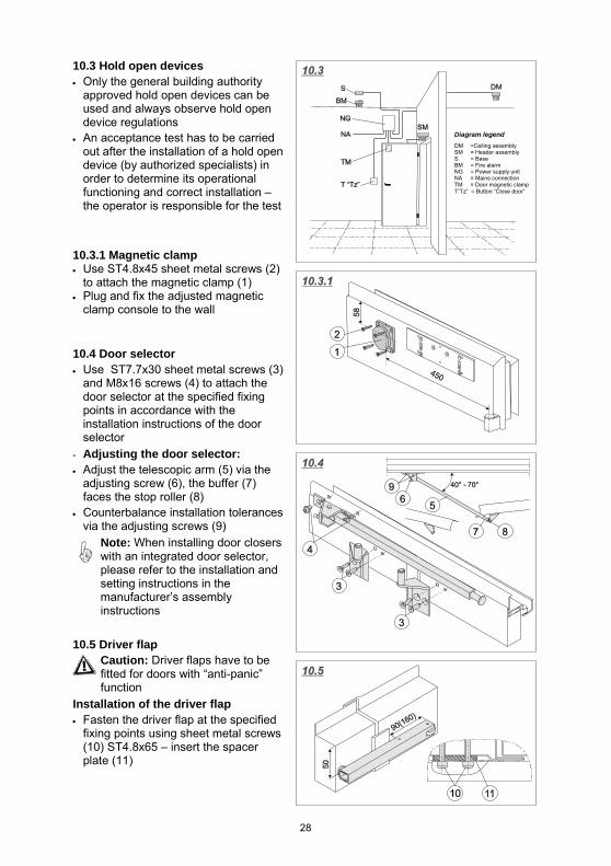
10.3 Hold open devices • Only the general building authority
approved hold open devices can be used and always observe hold open device regulations
• An acceptance test has to be carried out after the installation of a hold open device (by authorized specialists) in order to determine its operational functioning and correct installation – the operator is responsible for the test
10.3.1 Magnetic clamp • Use ST4.8x45 sheet metal screws (2)
to attach the magnetic clamp (1) • Plug and fix the adjusted magnetic
clamp console to the wall
10.4 Door selector • Use ST7.7x30 sheet metal screws (3)
and M8x16 screws (4) to attach the door selector at the specified fixing points in accordance with the installation instructions of the door selector
- Adjusting the door selector: • Adjust the telescopic arm (5) via the
adjusting screw (6), the buffer (7) faces the stop roller (8)
• Counterbalance installation tolerances via the adjusting screws (9)
Note: When installing door closers with an integrated door selector, please refer to the installation and setting instructions in the manufacturer’s assembly instructions
10.5 Driver flap Caution: Driver flaps have to be fitted for doors with “anti-panic” function
Installation of the driver flap • Fasten the driver flap at the specified
fixing points using sheet metal screws (10) ST4.8x65 – insert the spacer plate (11)
Diagram legend
DM =Ceiling assembly SM = Header assembly S = Base BM = Fire alarm NG = Power supply unit NA = Mains connection TM = Door magnetic clamp T”Tz“ = Button “Close door“
29
11. Locks and Door Fittings The locks comply with EN 12209, they can be replaced with locks with anti-panic function.
Fire protection doors can be fitted with a profile cylinder or with a tumbler (Bb) insert and keys contained in the door fittings pack.
The utilization of tumbler (Bb) inserts is not permitted for smoke protection and sound insulated doors.
11.1 Locks and door fittings for emergency exits and panic doors in accordance with EN 179 and EN 1125 11.1.1 General • These are two European-wide standards for the requirements and test methods for the
locks and latches of emergency exits and panic doors. • A locking system in accordance with these European standards always contains:
Locks – active and/or inactive door leaf lock Door fittings - active and/or inactive door leaf door fittings Accessories – fixing material, square pin, shoot bolt, switch lock Lock counterpiece(s) – locking plate, inactive door leaf lock
Emergency exits comply with EN 179 (a hazardous situation should not be associated with a panic situation.) Approved combination: Emergency exit lock with door handles.
Panic doors comply with EN 1125 (a hazardous situation should be associated with a panic situation.) Approved combination: Panic lock with bar handle. The panic bar handle should only be actuated in hazardous situations (not in permanent operation).
11.1.2 Caution: • Only fit lock systems in which the lock and door fittings have the same classification
code in accordance with EN 179 or EN 1125. This also applies for the retrofitting of replacements.
• The testing of door fitting combinations provided by the customer is the responsibility of the customer (contact us for approved door fitting combinations.) Stickers on the lock or pack indicate the approved functions.
• Block locks, additional locks and locking elements comply with EN 179 / 1125. • Attach a clearly visible pictogram which indicates correct utilization to the inside of the
door or in the exit direction immediately above the door fitting or on the actual door fitting if enough space is provided.
• The majority of emergency exit locks can only be opened correctly in emergency situations if the key has been removed. There are certain lock types for which the profile cylinder position is irrelevant for the panic function, for these types of locks the key does not have to be removed, or another possibility is the utilization of special cylinders which allow the panic function with an inserted key. Please contact us for more information.
11.1.3 Preventative measures: Please note that emergency exit and panic door lock systems have to be inspected at regular intervals. We recommended the conclusion of a maintenance contract for technically complex products.
30
11.2 Door handles • Install a profile cylinder [A] (provided
by the customer) or tumbler (Bb) insert [B]
• Insert the fastening screw (1) – and check the closing function.
• Insert the square pin (2) into the lock • Attach the steel base plate (3) with
return motion handle • Insert the sleeve nut (4) from the
outside • Screw the countersunk screw (5) into
the sleeve nut • Tighten the hexagon stud screw (6) • For tumbler (Bb) insert [B] – insert the
keyhole cover (7) • Clip on the cover plate (8) • For tumbler (Bb) insert [B] – engage
the tumbler (Bb) insert clip (9) Caution: Smoke protection and sound insulated doors should only be used in connection with a profile cylinder. Note: The door handles are fixed by the screws and sleeve nuts.
11.3 Geared handle for snap lock in the inactive door leaf [at the opposite hinge side as standard, alternatively at the hinge side]: • Use the countersunk screws (11) to
fasten the geared handle (10) [to screw in the second countersunk screw, move the handle to the left or the right so that the bore hole is accessible]
• Install the profile cylinder (12) [provided by the customer]
• Use the fastening screw (13) to fix the profile cylinder into position
• Check the functioning
31
11.4 Bar handle [A] Installation of a ECO bar handle at the lock side of the active door leaf and fixing with blind plate • Connect the base part of the bar
handle (1) to the handle or blind plate (4) using the countersunk screws (2) and sleeve nut (3)
• Use a self-tapping screw (5) to secure it
[B] Without blind plate Lock side inactive door leaf • Insert the square pin (6) • Connect the base part of the bar
handle (7) to the door leaf using the countersunk screws (8)
[C] Hinge side active and inactive door leaf • Connect the base part of the bar
handle (9) to the door leaf using the countersunk screws (10)
For further assembly information see the bar handle assembly instructions.
Swivel range of the bar handle 11.5 Profile cylinder (provided by the customer)
Caution: Smoke protection and sound insulated doors are only permitted with a profile cylinder
Determining the profile cylinder length • This is calculated from the
dimensions: A+31 / 31+B (= 40.5+40.5 for Teckentrup standard handles)
Profile cylinder length for the lockable geared handle: • Half cylinder = 30 / 00
Swivel range “X“ - For main lock (active
door leaf) = 45° - For shoot bolt (inactive
door leaf) = 30°
DM = Backset dimension
32
11.6 Assembly of the protective door fittings and profile cylinder
Ensure that: - The plate with the anti drilling
protection (AS) [steel insert] is attached facing the emergency exit side (GS) [see point 2.1.1]
- Protective door fittings and profile cylinder (see below) have been inserted
- The profile cylinder can protrude “X” max. 3 mm from the protective outer plate
• Assemble the security fittings according to the manufacturer's installation instructions
• Insert the profile cylinder (1) • Close the door and carry out
adjustments via the screw (2)
Allocation of the profile cylinder and security plates - WK2 • When assembling a security plate in accordance with DIN 18257 ES 1 (or EN 1906)
with ZA, a profile cylinder in accordance with DIN 18252 P2-BS (or EN 1303) [anti drilling protection] has to be used.
• When assembling a security plate in accordance with DIN 18257 ES 1 (or EN 1906) without cylinder cover, a profile cylinder in accordance with DIN 18252 P2-BZ (or EN 1303) [anti drilling and extraction protection] has to be used.
- WK3 • When assembling a security plate in accordance with DIN 18257 ES 2 (or EN 1906)
with cylinder cover, a profile cylinder in accordance with DIN 18252 P2-BS (or EN 1303) [anti drilling protection] has to be used.
• When assembling a security plate in accordance with DIN 18257 ES 2 (or EN 1906) without cylinder cover a profile cylinder in accordance with DIN 18252 P2-BZ (or EN 1303) [anti drilling and extraction protection] has to be used.
Security plates and profile cylinder have to be monitored by DIN CERTCO. Allocation of the profile cylinders and security plates to the resistance classes
Required:
Door resistance class
Profile cylinder in accordance with DIN 18252
(or EN 1303) [anti drilling and extraction protection 1)]
- class
Security plate in accordance with DIN 18257 (or EN
1906) 1) - class
WK2 2 ES1 WK3 2 ES2
1) The extraction protection integrated in the profile cylinder is not required if this is integrated in the security plate, i.e. security plate with cylinder cover (anti drilling protection)
33
12. Electrical Components 12.1 Reed contact Teckentrup standard [A] • Is fitted as standard, otherwise insert
the contacts and attach them with the enclosed screws
Smaller components [B] • An insert is additionally inserted in the
plastic receiver • The distancing feet (DF) may have to
be removed, depending on the height of the contacts.
Round design [C] • Clip on the contacts
12.2 Bolt contact in the inactive door leaf • Insert the cable through the empty
conduit and screw on the bolt contact • Attach the lock plate
in the frame • Attach the lock plate • Insert the cable through the empty
conduit and screw on the bolt contact
34
12.3 Electronic door opener eff-eff [A] 143 / [B] 142 • Connect the door opener • Push it into the frame or door leaf and
screw it into position
Setting the latch bolt contact - By moving the door opener lock
plate for eff-eff 142 • Slightly loosen the screws and set by
moving the door opener
- By moving the door opener latch for eff-eff 142 and 143
• Slightly loosen the screws and set by moving the door opener latch
12.4 Cable junction • Use the supplied screws to attach the
cable junction to the door and then to the frame
12.5 Door leaf cut-outs • Core holes in the door leaf which a
diameter greater than 15 mm have to be lined with a material that forms an insulating layer (e.g. “ROKU strip” or “Promaseal-PL”
• Seal with silicone
35
13. Further Door Versions 13.1 Glazing 13.1.1 Installation in fire and smoke protection doors:
• Only use approved glass • The glass should only be
replaced by specialists • One side has to be sealed with
silicone for smoke protection doors
13.1.2 Multi-purpose doors – aluminium glass holding strip - Installation (observe the inside [ I ] and outside [A]!): • Attach the clip connectors (1+2) onto
the aluminium glass holding strips (3) • Insert the seals (4 [A] +5 [ I ]) • Attach the outer glass holding strip • Insert the pane of glass in the middle • Clip on the inner glass holding strip
- Replacing: • Carefully remove the seal (5) • Snap off the clip connectors (1+2) • Insert new clips (1+2) • Replace the pane • Assemble glass holding strips as for
installation
13.2 Upper part for MP doors with integrated upper part [A] • Additionally plug and fix the frame at
the top [see point 2.4] • Use M8 screws (6) to fasten the upper
part at the square profiles • Insert the seal (7) in the seal retainer
(8) at the upper part with attached frame profile [B] • Place the upper part on the frame and
weld it l≥20; e≤300 • Close the imposts from the rear with
the cover plate (9)
Important: Observe the clearance between the door leaf and the upper part!
36
13.3 Door functioning as an outer door - Doors are equipped with a rain guard and weatherboard. Water drainage has to be ensured. Without top door closer in aluminium • Connect the upper frame part prior to
door installation
With top door closer in steel plate • If necessary, screw to the header (1)
[e.g. Fischer plug S6 with M5x40 hexagon head screw] or weld to the upper frame part (S) = l>20, e<750
13.4 Weatherboard • Possibly use a threshold with water
drain channel • Attach the weatherboard to the
outside using screws or rivets
14. Disassembly of Doors Caution – always remember to: • Remove or put components and
accessories out of operation. • Wedge doors and ensure they
cannot fall down • Loosen screws at the hinges • Tap out hinge bolts
15. Painting (surface treatment) • The door leaves and frame are coated with a 2K acrylic primer and can be painted with
the listed paint systems: Synthetic resin top coat, 2K-PUR top coat or epoxy ester resin top coat
- Recommendation: • Sand the object, particularly for watery paint systems, to increase adhesion • Prior to painting, only coat galvanized parts with coating materials which are suitable
for galvanized surfaces • The top coat or finish coat should be carried out after 3 months at the latest
Caution: The application of top coats containing alkyd resin on galvanized substrates can lead to a later loss of adhesion of the overall coating on outside surfaces which are exposed to harsh weather conditions.
37
16. Maintenance Instructions • Maintenance is the responsibility of the property owner. The property owner can carry
out the required maintenance tasks or employ a specialist company to do it. • To ensure correct functioning of the fire, smoke protection and sound insulated doors,
professional maintenance should be carried out every 12 months (more often for frequently used doors).
16.1 Maintenance tasks Door components Required maintenance tasks
Ope
ratio
nal
chec
k
Cle
an *1
)
Lubr
icat
e/O
il ac
id-fr
ee
grap
hite
, gr
ease
or
resi
n-fre
e oi
l R
etig
hten
fa
sten
ing
scre
ws
*2)
Rec
tify
*2)
Com
men
t
Door version Frame X X X Repair surface defects (cracks) Masonry connection
X X Repair defects (loose masonry, cracks)
Door leaf X X Repair surface defects (cracks) Infill (glass, ventilation)
X X X Repair sealing defects (silicone), clean ventilation slots
Upper part Fixed X X X Fixed glazing X X X Opening glazing X X X X X
Repair surface defects (cracks). Check and lubricate locking system (e.g. catches and hinges)
Bottom threshold X X X X Repair surface defects (cracks) (to ensure correct sealing)
Fittings Seals X X X Replace brittle or damaged seals Hinges X X X X X Replace defective parts Handle, knob X X Check the securing pin Mortise lock (safety catch, lock)
X X X X X Check the double-rotating connection of the lock, replace defective locks, if necessary
Lock plate X X X X Check the adjustable safety catch parts, if available, readjust, if necessary
Additional locking Without profile cylinder
X X X X
With profile cylinder X X X X Top door closer (OTS)
X X X X X Check the closing speed approx. 6 sec from 90°) and the limit stop
Retractable bottom seal
X X X X Ensure sealing along the entire width (regulate via wedges), replace brittle or damaged seals
Spyhole X
*1) Cleaning: Only use non-corrosive cleaning agents which do not contain hazardous components. Do not use scouring agents, abrasive cleaning agents, wire wool or similar products. Clean sealing profiles with a clean cloth, warm water and a rinsing agent. Never use petrol, benzene, turpentine or similar products for cleaning tasks.
*2) The immediate elimination of defects is imperative.